

Digital Equipment RA70, RA72, RA73, SA7 series, RA71 Reference Manual

RA7x/SA7x Pocket
ReferenceGuide
Order Number EK–RSA7X–PG–002
This guide contains quick-reference information for RA7x
disk drives (RA70, RA71, RA72, and RA73) and SA7x
enclosures.
Digital Equipment Corporation

August 1992
The information in this document is subject to change
without notice and should not be construed as a
commitment by Digital Equipment Corporation. Digital
Equipment Corporation assumes no responsibility for any
errors that may appear in this document.
Possession, use, duplication, or dissemination of the
software described in this documentation is authorized
only pursuant to a valid written license from Digital or the
third-party owner of the software copyright.
No responsibility is assumed for the use or reliability of
software on equipment that is not supplied by Digital
Equipment Corporation.
Copyright © Digital Equipment Corporation 1991, 1992
All Rights Reserved.
Printed in U.S.A.
FCC NOTICE: The equipment described in this manual
generates, uses, and may emit radio frequency energy.
The equipment has been type tested and found to comply
with the limits for a Class A computing device pursuant to
Subpart J of Part 15 of FCC Rules, which are designed to
provide reasonable protection against such radio frequency
interference when operated in a commercial environment.
Operation of this equipment in a residential area may cause
interference, in which case the user at his own expense may
be required to take measures to correct the interference.
The following are trademarks of Digital Equipment
Corporation: DEC, DSA, DSDF, HSC, HSC50, HSC70,
KDA, KDA50, KDB50, KDM, MicroVAX, PDP-11, RA, SA,
SDI, UDA, UNIBUS, VAXsimPLUS, and the DIGITAL logo.

Contents
Introduction and Related
Documentation . . . . . . . . . . . . . . . 1
RA7x Characteristics . . . . . . . . . . . 2
Thermal Stabilization Specifications . . 3
Setting Capacity Indicator Switch . . . 4
Troubleshooting . . . . . . . . . . . . . . . 6
RA7x Parts . . . . . . . . . . . . . . . . . . 10
SA7x Parts . . . . . . . . . . . . . . . . . . 13
RA7x Electronics Block Diagrams . . . 15
RA71-RA73 Support . . . . . . . . . . . . 16
RA7x Drive Status Information . . . . . 19
OCP Error Codes . . . . . . . . . . . . . . 30
Drive Error Codes and Fault Numbers 34
iii

iv Contents
Figures
1 RA71/RA72 Capacity Indicator Switch 5
2 Drive Internal Error Log . . . . . . . . . . 7
3 Troubleshooting Flowchart . . . . . . . . 9
4 RA70 Exploded View . . . . . . . . . . . 11
5 RA71-RA73 Exploded View . . . . . . . 12
6 SA7x Enclosure Exploded View . . . . 14
7 RA70 Electronics—Simplified Block
Diagram . . . . . . . . . . . . . . . . . . . . 15
8 RA71-RA73 Electronics—Simplified
Block Diagram . . . . . . . . . . . . . . . . 15
9 RA7x Drive Status . . . . . . . . . . . . . 20
10 RA7x Response Opcode (Byte 1) . . . 21
11 RA7x Lower Unit (Byte 2) and High
Unit and Subunit Mask (Byte 3) . . . . 21
12 RA7x Request Byte (Byte 4) . . . . . . . 22
13 RA7x Mode Byte (Byte 5) . . . . . . . . 23
14 RA7x Error Byte (Byte 6) . . . . . . . . . 24
15 RA7x Controller Byte (Byte 7) and
Retry Count (Byte 8) . . . . . . . . . . . . 25
16 RA7x Previous Command Opcode
(Byte 9) . . . . . . . . . . . . . . . . . . . . 26
17 RA7x Drive State Byte (Byte 10) . . . . 27
18 RA7x Current Cylinder Address (Bytes
11 and 12) . . . . . . . . . . . . . . . . . . 27
19 RA7x Current Group (Byte 13) . . . . . 28
20 RA7x Drive Error Code (Byte 14) . . . . 28
21 RA70 OCP Code Byte; RA71-RA73
Fault Number Byte (Byte 15) . . . . . . 28
22 SA7x OCP . . . . . . . . . . . . . . . . . . 29

Contents v
Tables
1 Related Documentation . . . . . . . . . . 1
2 RA7x Characteristics . . . . . . . . . . . 2
3 Thermal Stabilization Times . . . . . . . 3
4 RA7x Part Numbers . . . . . . . . . . . . 10
5 SA7x Part Numbers . . . . . . . . . . . . 13
6 VAX Diagnostics for RA71-RA73 . . . . 16
7 Operating Systems for RA71-RA73 . . 17
8 SDI Controllers for RA71-RA73 . . . . . 18
9 Retired VAX Supervisor Programs . . . 18
10 OCP Error Codes . . . . . . . . . . . . . . 30


RA7x/SA7x Pocket Reference Guide 1
Introduction and Related Documentation
This guide contains quick-reference information for RA7x
disk drives (RA70, RA71, RA72, and RA73) and SA7x
enclosures.
For more complete information about RA7x disk drives and
SA7x enclosures, see the related documentation listed in
Table 1.
Table 1 Related Documentation
Document Title Order number
RA70 Disk Drive Technical
Description Manual EK–ORA70–TD
DSA Troubleshooting Flowchart EK–DSATF–TM
BA27 Field Maintenance Print Set MP–01429
SA7x Support Print Set EM–01435
SA7x Field Maintenance Print Set MP–01435
SAxxx Storage Array Configuration
Guide EK–SAXXX-CG
SA7x Enclosure User Guide EK–OSA7X–UG
SA7x Enclosure Service Manual EK–OSA7X-SM
RA7x Disk Drive Service Manual EK–ORA7X-SM
RA70 Field Maintenance Print Set MP–01428
RA71/RA72 Support Print Set EM–01434
RA71/RA72 Field Maintenance Print
Set MP–01434
RA73 Field Maintenance Print Set MP–01439
RA73 Support Print Set EM–01439

2 RA7x/SA7x Pocket Reference Guide
RA7x Characteristics
Table 2 lists the characteristics of RA70 and RA71-RA73
disk drives.
Table 2 RA7x Characteristics
Characteristics RA70 RA71 RA72 RA73
Total Number of Heads
12 15 21 22
Number of Data Heads
11 14 20 21
Number of Dedicated Servo Heads
1 1 1 1
Surfaces Containing Data and Embedded Servo
Information
11 14 20 21
Formatted Data Storage Capacity
280
MB
700
MB
1.0
GB
2.0
GB
Although RA70 and RA71-RA73 disk drives are very similar
in appearance, they differ structurally and electronically.
The RA70 shoe plate is not interchangeable with those for
the RA71-RA73 disk drives. None of the RA7x HDAs or
ECMs are interchangeable.

RA7x/SA7x Pocket Reference Guide 3
Thermal Stabilization Specifications
When condensation is visible on the enclosure or the disk
drive, stabilize the unit in the operating environment for six
hours, or until the condensation is no longer visible.
When condensation is not visible on the enclosure or
disk drive or enclosure, see Table 3 for correct thermal
stabilization times.
Table 3 Thermal Stabilization Times
Temperature
Range Degrees
C
60 to 66 140 to 151 3 hours
50 to 59 122 to 139 2 hours
40 to 49 104 to 121 1 hour
30 to 39 86 to 103 30 minutes
18 to 29 65 to 85 No stabilization
10 to 17 50 to 64 30 minutes
0 to 9 32 to 49 1 hour
–10 to –1 14 to 31 2 hours
–20 to –11 –4 to 13 3 hours
–30 to –21 –22 to –5 4 hours
–40 to –31 –40 to –21 5 hours
Temperature
Range Degrees
F
Minimum
Stabilization
Time
required

4 RA7x/SA7x Pocket Reference Guide
Setting Capacity Indicator Switch
Set the Capacity Indicator switch on the RA71 and RA72
disk drives, shown in Figure 1, as follows:
NOTE
The capacity indicator switch has no function on an
RA73.
• RA71 (700 MB)
Capacity Indicator switch should be up (on).
• RA72 (1 GB)
Capacity Indicator switch should be down (off).
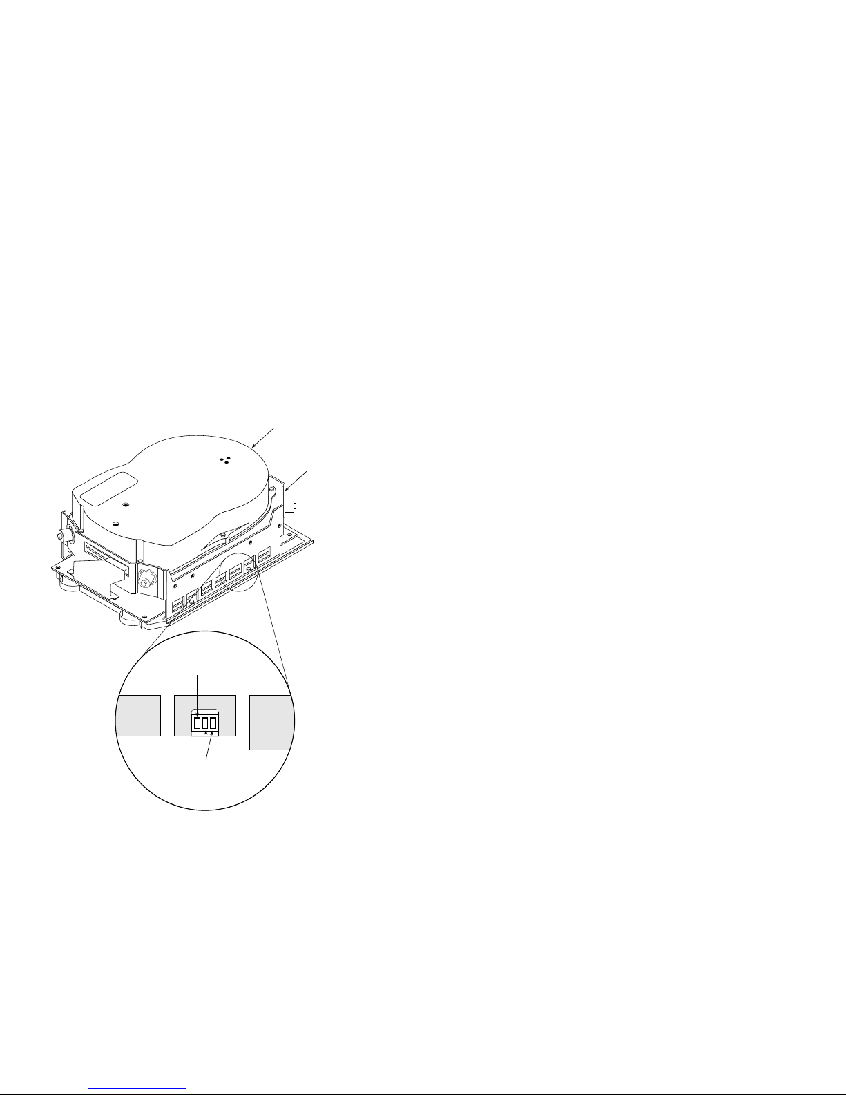
RA7x/SA7x Pocket Reference Guide 5
UNIT SELECT SWITCHES
CAPACITY INDICATOR SWITCH
Figure 1 RA71/RA72 Capacity Indicator Switch
TOP COVER HDA
CHASSIS
COM-R002

6 RA7x/SA7x Pocket Reference Guide
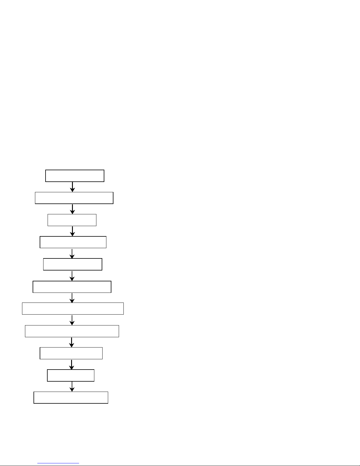
Troubleshooting
This section includes troubleshooting tips, an example of
a drive internal error log (Figure 2), and a troubleshooting
flowchart (Figure 3).
Tips for DSA Troubleshooting
Observe the following tips when troubleshooting DSA
products:
• Avoid formatting new HDA units.
• Note that EDC errors are not drive problems.
• Note that forced errors are not necessarily HDA
problems.
• Avoid running standalone diagnostics unless drive
or system error logs are unavailable and all other
troubleshooting techniques have failed.
• Ensure that equipment is thermally stabilized before
attempting to power up.
• Use proper ESD grounding methods. Equipment is
highly susceptible to static damage.
• Adhere to the service delivery strategy as outlined in
specific component service manuals.
RA7x/SA7x Pocket Reference Guide 7
Figure 2 Drive Internal Error Log
Error Log Entries for Drive 0
Select starting entry location [(7), 1-191] ? 8
Enter how many error log entries to display [(191), 0-191] ? 30
Pause and prompt after every 10 error log entries [(Y), N] ? Y
Drive
Max#Entries
Type
RA70 191 580 125000
Entry
Entry
Count
Loctn
(D)
(D)
8
7
6
5
4
3
2
1
191
(D) = decimal, (A) = ASCII, (H) = hex
Seeks/Power-on
(D)
Err
Typ
(A)
2 00
DE
3
DE
3
DE
3
3
3
3
3
2
Err
Code
(H)
39
E7
E9
00
00
00
00
00
(D)
Seek
Count
(D)
453122
452446
452446
451699
451699
451616
451616
MFG
Code
(H)
0
0
Cum. Seeks
00 00 00 00 00 00 00 00 00 00 00 passed.test
32
33
34
00
00
00
00
00
Cum. Power-on
(D)
Drive-Specific Hex Data
Byte 0-9, right to left
00 00 09 0A 00 00 00 04 32 58
00 00 09 04 FF FB 0B 05 42 75
00 00 09 03 FF FB 0B 05 12 9D
00 00 09 02 02 F6 05 04 79 A0
00 00 09 01 02 F6 05 04 7A BB
00 00 09 00 00 00 00 00 42 A0
00 00 09 00 00 00 00 00 40 C0
00 00 00 00 00 00 00 00 00 00
(D)
7200
(H)
Minutes
(H)
00001C20
Drive Err
Message
(A)
wrg&off.trk
inc.lhd.sek
exp.sek.tmr
drv.sys.ini
exp.onl.atn
drv.sys.ini
drv.pwr.rst
passed.test
1 2 3 4 5 6
1. Drive error code—see “Drive error codes and fault numbers” in this guide for an explanation of
these codes
2. Manufacturing code (OCP code)—see the OCP error codes table in this guide for an expla-
nation of these codes
3. Logic Processor Number of Minutes (bytes 9, 8, 7, and 6)
4. Servo Processor Destination Cylinder (bytes 5 and 4)
7 8 9
5. Servo Processor Destination Logical Head Number (byte 3)
6. Servo Processor Physical State Number (byte 2)—see the following page for a list of physical
state numbers
7. Logic Processor Logical State Bit Flags (byte 1)—see the following page for a list of logical
state bit numbers
8. Logic Processor Fault Number (byte 0)
9. Drive error message—see "Drive error codes and fault numbers" in this guide for a translation
of these error messages
COM-0211

8 RA7x/SA7x Pocket Reference Guide
Servo Processor Physical State Numbers (Byte 2)
00–reset
01–retract (unload heads)
02–spin-up motor
03–spin-down motor
04–detent (track follow)
05–seek to cylinder
06–return to cylinder zero (load heads)
07–recalibrate
08–diagnostic
The following State Numbers apply only to the
RA73:
09–fault
0A–PLL lock
Logic Processor Logical State Bit Flags (Byte 1)
Bit 07–hard error
Bit 06–soft fault
Bit 05–internal read/write ready
Bit 04–drive timing enabled
Bit 03–logical attention
Bit 02–logical topology state
Bit 01–logical available state
Bit 00–logical available state
NOTE
For more information about the physical state numbers
and logical state bit flags, see the RA7x Disk Drive
Service Manual.
RA7x/SA7x Pocket Reference Guide 9
Figure 3 Troubleshooting Flowchart
Talk to the system operator.
Check the OCP for fault indications.
Run VAXsimPLUS.
Analyze the HSC Console Log.
Analyze the Host Error Log.
Analyze the Drive Internal Error Log.
Correlate error codes to the probable failing FRU.
Use host-based diagnostics as a last resort.
Identify prime suspect FRU.
Replace failing FRU.
Verify that the drive is operational.
COM-R080

10 RA7x/SA7x Pocket Reference Guide
RA7x Parts
Table 4 lists RA7x part numbers. Figures 4 and 5 shows
exploded views for RA70 and RA71-RA73 disk drives.
Table 4 RA7x Part Numbers
Part Part Number
RA70 Disk Drive
ECM
HDA
Shoe plate
RA71 Disk Drive
ECM
HDA
Shoe plate
RA72 Disk Drive
ECM
HDA
Shoe plate
RA73 Disk Drive
ECM 54-21396-01
HDA 70-28699-01
Shoe plate 70-29408-01
70-22494-01
70-21946-01
70-22474-01
54-20826-01
70-28492-01
70-29408-01
54-20826-01
70-28492-02
70-29408-01
RA7x Disk Drive
Electronically conductive field
service grounding kit
29-11762
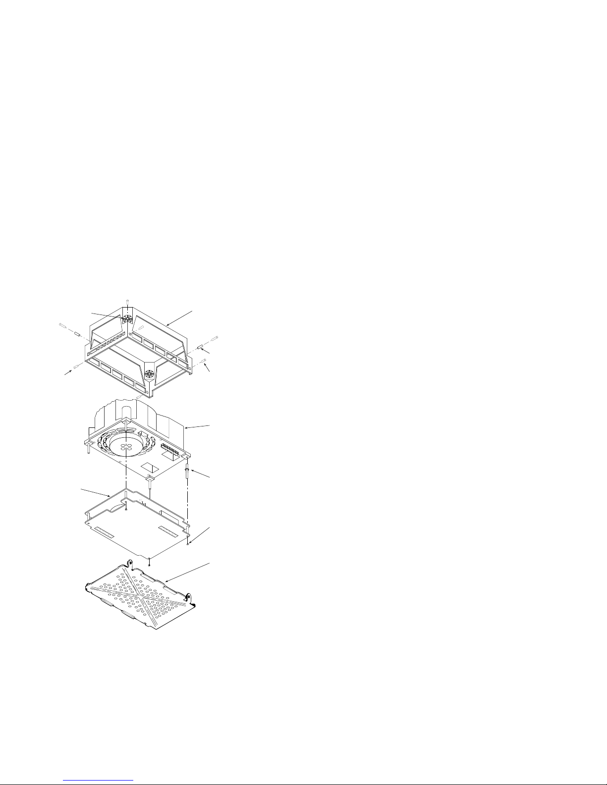
RA7x/SA7x Pocket Reference Guide 11
Figure 4 RA70 Exploded View
SHOCK
ISOLATOR
SCREW
ELECTRONIC
CONTROL
MODULE
CHASSIS
GROMMET
BUSHING
SCREW
FOR SHOE
PLATE
ATTACHMENT
TOP
COVER/HDA
BASEPLATE
CORNER
POSTS
MODULE
RETENTION
KEP NUT
SHOE
PLATE
COM-R004
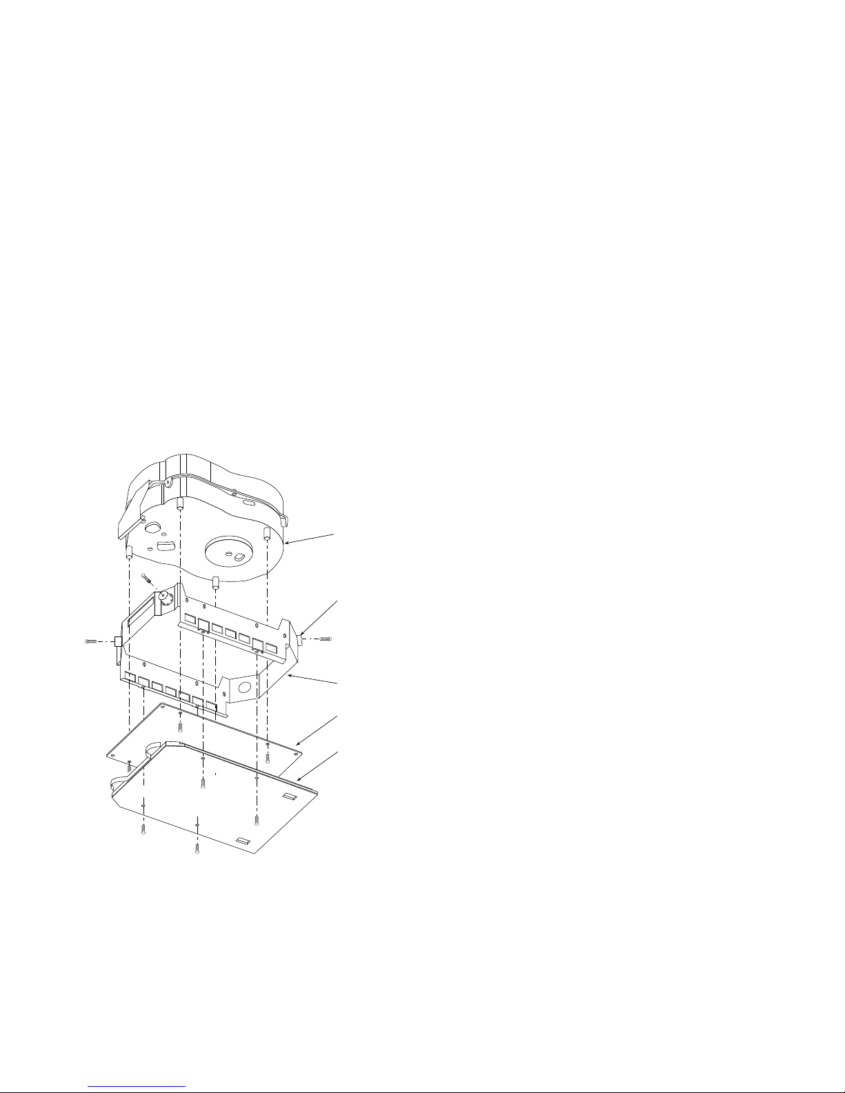
12 RA7x/SA7x Pocket Reference Guide
Figure 5 RA71-RA73 Exploded View
HDA
ASSEMBLY
SHOCK
ISOLATOR
CHASSIS
ECM
SHOE
PLATE
CXO-3519A-MC_R

RA7x/SA7x Pocket Reference Guide 13
SA7x Parts
Table 5 contains a list of part numbers. Figure 6 shows an
exploded view of an SA7x enclosure.
Table 5 SA7x Part Numbers
Part Part Number
Chassis (enclosure assembly) 70-23901-01
Drive position filler 70-23970-01
Fan assembly 70-24440-01
Frame assembly 70-23913-01
OCP
assembly
cable, long 80 cm (31.5 in)
cable, short 35.6 cm (14 in)
Power cord 17-00442-19
Power harness 70-26255-01
Power supply H7869-AK
Pushbutton switch
with green LED 12-12717-13
Pushbutton switch cap
left front
left rear
right front
right rear
SDI Cables
External cable assembly
Internal cable assembly
Internal SDI cable harness
Transition board
Board 1
Board 2
Transition interface cables 17-02147-01
70-25696-01
70-26254-02
70-26254-01
12-14027-14
12-14027-15
12-14027-13
12-14027-12
70-26257-01
70-26256-01
17-01699-01
54-19171-01
54-19015-01
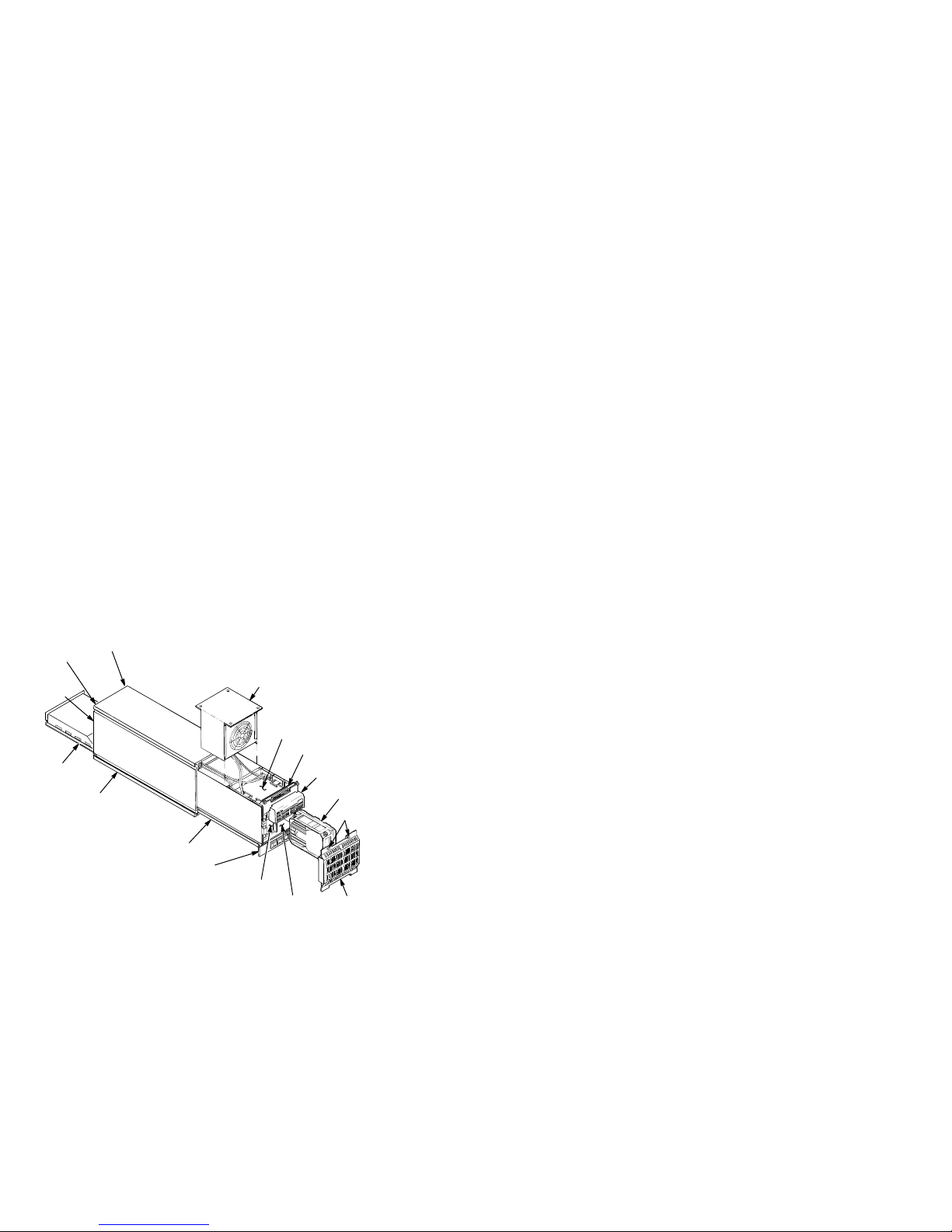
14 RA7x/SA7x Pocket Reference Guide
Figure 6 SA7x Enclosure Exploded View
RIGHT REAR
DISK DRIVE
LEFT REAR
POSITION
DISK DRIVE
POSITION
REAR
COVER
(NOT
SHOWN)
POWER
SUPPLY
CHASSIS
FAN
TRANSITION
BOARD 2
TRANSITION
BOARD 1
OPERATOR
CONTROL
PANEL
RA70 DISK
DRIVE SHOWN
MOUNTING
SCREWS
FRAME
DRIVE POWER
SWITCH PANEL
LEFT FRONT
DISK DRIVE
POSITION
RIGHT FRONT
DISK DRIVE
POSITION
FRONT
COVER
CXO-1845D_S_R
RA7x/SA7x Pocket Reference Guide 15
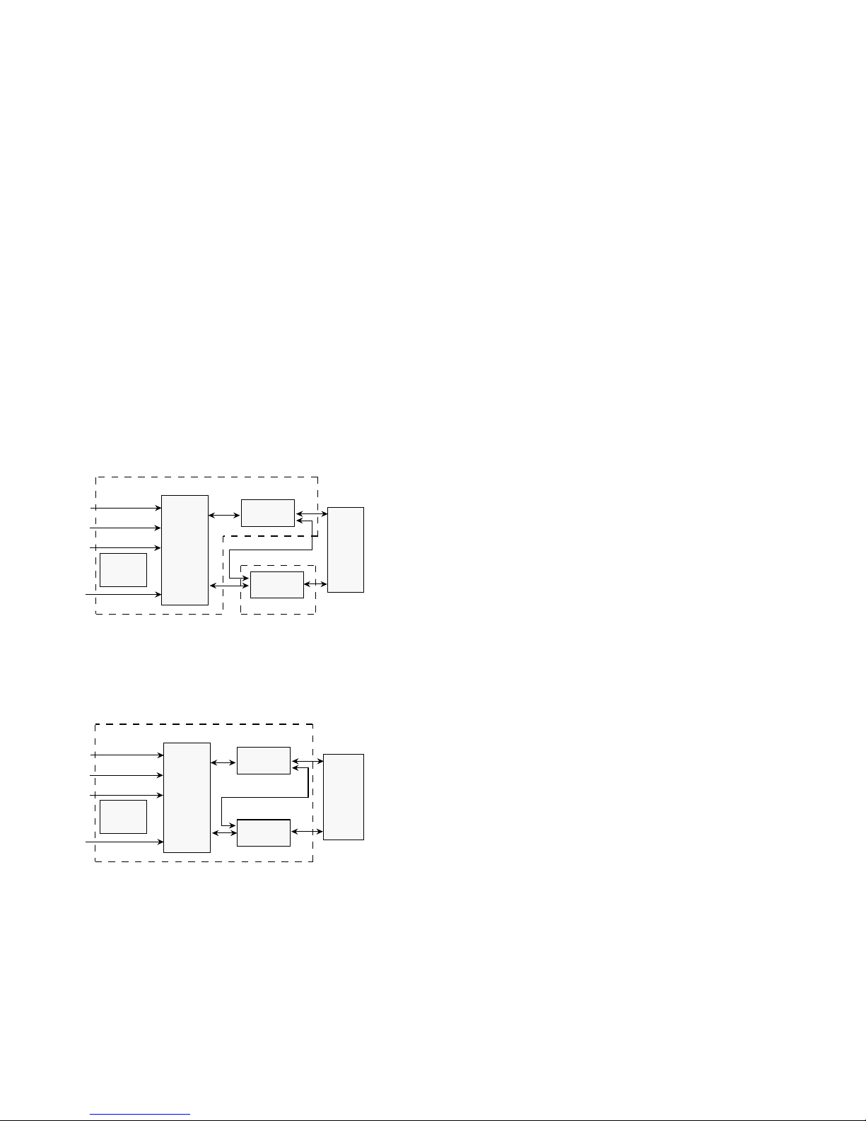
RA7x Electronics Block Diagrams
Figures 7 and 8 are electronics block diagrams for RA70
and RA71-RA73 disk drives.
Figure 7 RA70 Electronics—Simplified Block Diagram
Logic Read/Write Module
Power J4
Port B J2
Port A J1
Remote
OCP J3
I/O Logic
Local OCP
Read/Write
HDA
Servo/Spindle
Servo/Spindle Module
COM-R082
Figure 8 RA71-RA73 Electronics—Simplified Block
Diagram
Electronic Control Module
Power J4
Port B J2
Port A J1
Remote
OCP J3
I/O Logic
Local OCP
Read/Write
Servo/Spindle
HDA
COM-R081

16 RA7x/SA7x Pocket Reference Guide
RA71-RA73 Support
Tables 6, 7, and 8 list the minimum versions of operating
systems, diagnostics, and SDI controllers that support
RA71-RA73 disk drives in Release 43.
The diagnostics and VAX supervisor programs in Table 6
all recognize RA71-RA73 disk drives. The retired VAX
Supervisor programs in Table 9 do not recognize RA71RA73 disks drives. However, they will properly test and
operate the RA71-RA73 disk drives with the above disk
drive diagnostics when the disk drives are "attached as
RA70 disk drives" during program setup.
Table 6 VAX Diagnostics for RA71-RA73
Diagnostic
Supervisor Description Version
EVRAE Generic MSCP Exerciser 4.3
EVRLB UDA/KDB50 Basic Disk
Formatter
EVRLF UDA/KDB50 Basic
Subsystem Diagnostic
EVRLG UDA/KDB50 Disk Drive
Exerciser
EVRLJ VAX UDA/KDB50/KDM70
Exerciser
EVRLK VAX Bad Block Replace
Utility
EVRLL VAX Disk Resident Error
Log Utility
EVRLM KDM70 EEPROM Update
Utility
EVRLN DUP Control Program 1.6
EBSAA Supervisor, 8200, 8250,
8300, 8550 (Bereta)
ELSAA Supervisor, 5800, 6000-2xx,
6000-3xx
EMSAA Supervisor, 6000-5xx 14.4-PT1
ERSAA Supervisor, 6000-4xx 14.4-PAT1
EVSBA VAX Diagnostic Autosizer 7.5
EVSBB VAX Online Autosizer 4.0
8.3
10.4
10.3
4.3
4.3
3.3
1.6
14.4-PAT1
14.4-PAT1

RA7x/SA7x Pocket Reference Guide 17
Table 7 Operating Systems for RA71-RA73
Operating
Systems
Software
RA71/RA72
Minimum
Version
VMS 5.4-2
1
RA73
Minimum
Version
5.5-2
VAXsimPLUS 1.6 2.0
ULTRIX-32 4.2 4.3
VAXELN 4.3 4.3-x
VAX System V 3.2.1 Not planned
1
The Error Log Formatter (ERF) Version 5.4-2 must be
upgraded to Version 5.4-2 (0001) to support RA71-RA72.
Version 5.5-2 is required to support the RA73 disk drive.
 Loading...