

Digital Equipment Pro-Face PL-6700 43 Series User Manual

PL-6700 43Series
Panel Computer
User's Manual
Digital Electronics Corporation

Preface
Introduction
Introduction
Digital’ s PL-6700 series of Panel Computers are multipurpose factory
automation (FA) computers, which embody Digital’s latest, cost-effective
architecture.
Before using Digital’s PL-6700 Series of Panel Computers, which includes
the PL-6700T and which is hereafter referred to as the “ PL ”, be sure to
read this manual thoroughly to familiarize yourself with the PL’s operation
procedures and functions. Be sure to keep this manual handy for future
reference.
NOTE:
1. It is forbidden to copy the contents of this manual in whole, or in part, without the
permission of the Digital Electronics Corporation.
2. The information in this manual is subject to change without notice.
3. This manual was written with care; however, if you should find any error or
omissions, please contact Digital Electronics and inform them of your findings.
4. Please be aware that we are not responsible for any damages resulting from the
use of our products, regardless of article 3 above.
5. Specifications set out in this manual are for overseas products only, and, as a
result, some differences may exist between the specifications given here and the
Japanese ones.
All Company / Manufacture names used in this manual are the registered
trademarks of their respective companies.
© Copyright June 1998, Digital Electronics Corporation
PL-6700 43 Series User’s Manual i
Safe Product Usage
Safety Icons
Preface
Safe Product Usage
This manual contains a variety of safety markings to help you safely and
correctly operate Digital’s PL-6700 series of Panel Computers.
This manual uses the two icons below to call attention to information important for the safe and correct use of the PL. Please pay attention to these
icons and follow all instructions given by them.
The safety icons and their meanings are:
Indicates a potentially hazardous situation which could result
in serious injury or even death, if the instructions are not
followed.
Indicates a potentially hazardous situation which could result
in minor injury or equipment damage if the instructions are
not followed.
PL-6700 43 Series User’s Manualii

Preface
Essential Safety Precautions
Essential Safety Precautions
Be sure to follow the instructions given below to ensure the safe use of the PL.
T o avoid a possiblity of electrical shock, be sure to connect the power cord
to the PL before connecting it to the main power supply .
A fire or electrical shock may result if voltages are used with the PL that are
beyond the specified range. Be sure to only use the specified voltage.
Before opening the PL ’ s protective cover , be sure to turn the unit’ s power
OFF . This is because the PL ’ s internal parts carry high voltages.
T o avoid fires or electrical hazards, do not modify the product in any way .
Do not create touch panel switches that are used to either control or to
ensure the safety of equipment and personnel. Mechanical switches,
such as an emergency stop switch, a deadman (two-handed) start
switch, etc., must be installed and operated via a separate control
system.
If metal particles, water or other types of liquids contact any of the PL’ s
internal parts, immediately turn the unit’s power OFF, unplug the power
cord, and contact either your dealer or Digital Electronics Corporation.
Read and understand Chapter 4 “Installation and Wiring” thoroughly in
order to select an appropriate installation location for the PL.
Before either plugging in or unplugging a board or interface connector ,
be sure to turn the PL’s power OFF.
To prevent a possible explosion, do not install the PL in areas contain-
ing flammable gases.
The PL is not appropriate for use with aircraft control devices, aero-
space equipment, central trunk data transmission (communication)
devices, nuclear power control devices, or medical life support equipment, due to these devices’ inherent requirements of extremely high
levels of safety and reliability.
When using the PL with transportation vehicles (trains, cars and ships),
disaster and crime prevention devices, various types of safety equipment, non-life support related medical devices, etc. redundant and/or
failsafe system designs should be used to ensure the proper degree of
reliability and safety.
Do not push on the PL ’ s screen too strongly , with either your finger or
PL-6700 43 Series User’s Manual iii
General Safety Precautions
General Safety Precautions
Follow the instructions given below for correct and safe use of the
PL.
Do not push on the PL ’s screen too strongly , with either your finger or with a
hard object. Excessive pressure can scratch, crack or damage the screen.
If the screen becomes dirty or smudged, moisten a soft cloth with diluted neutral
detergent, wring the cloth well, and wipe the display. Do not use thinner or
organic solvents.
Do not use a pointed object, such as a mechanical pencil or screwdriver, to
press any of the touch panel’s switches, since they can damage the display .
A void exposing and operating the PL in direct sunlight, high temperatures and
humidity , and in areas where excessive dust and vibration will occur.
A void using the PL in areas where sudden, extreme changes in temperature can
occur. This may cause condensation to form inside the unit, possibly leading to
an accident.
Preface
T o prevent the PL from overheating, be sure its air circulation vents are clear and
clean, and keep the unit’s operation area well-ventilated.
A void operating or storing the PL near chemicals, or where chemicals can come
into contact with the unit.
Since the PL-6700’s hard disk drive (HDD) is a consumable item, i.e. it has a definite usage
lifetime, be sure to back up its data frequently and perform regular maintenance.
T o prevent file damage, be sure to shut down your PL ’s OS before turning the PL OFF .
Notes on Handling the LCD
The PL's LCD contains a strong irritant. If the panel is ever cracked and the LCD's
liquid contacts your skin, be sure to wash it with running water for at least 15 minutes.
If any of this liquid should enter your eye, be sure to flush your eye with running water
for more than 15 minutes, and see a doctor immediately .
The current brightness of the LCD screen will depend on the screen's current
display and the LCD's contrast adjustment. Any brightness variations that result
are normal for LCD displays.
There are minute grid-points (Dark or light points) on the LCD surface. These
points are not defects and are a part of the PL panel’ s design.
Occasionally crosstalk (shadows appearing on extended display lines) will appear on the
display . This phenomenon is a common attribute of LCDs and is not a defect.
The displayed color will look different when viewed from an angle outside the
specified view angle. This is also normal.
PL-6700 43 Series User’s Manualiv
Preface
!!
!
!!
Important
General Safety Precautions
Displaying a single screen image for long periods of time can cause an
afterimage to remain on the screen. T o correct this, turn the unit OFF
for 5 to 10 minutes, then ON again. This phenomenon is a common
attribute of the LCDs, and is not a defect. T o prevent this ef fect, you
can:
- use the Display OFF feature; if the same image is to be displayed for a
long period of time.
- change the screen display periodically to prevent the displaying of a
single image for a long period of time.
For further information about the PL’s LCD panel, please contact your local
PL distributor .
• The Digital Electronics Corporation cannot be held responsible or provide any compensation for damage(s) caused by
the loss of data stored in the PL-6700’s hard disk drive
(HDD). It is therefore strongly suggested that all important
data and software be backed up regularly to an external data
backup device.
• Please be aware that the Digital Electronics Corporation
bears no responsibility for any damages resulting from the
customer’s application of this unit’s hardware or software.
• Please be aware that the Digital Electronics Corporation will
not provide compensation for any damages occurring as a
result of problems with this unit’s software or hardware.
PL-6700 43 Series User’s Manual v

Notes on UL Application / Notes on CE Marking
Notes on UL Application
The PL6700-T4* are (c)UL 1950 recognized products. (UL File No. E177793).
Please pay special attention to the following instructions when applying for
UL approval for machinery which includes one of these PL units built in.
Machinery with a PL mounted in it requires UL inspection for the combination of the PL and the machinery .
• PL conforms as a component to the following standards:
UL 1950, Third Edition, dated July 26, 1995 (Standard for Safety of
Information Technology Equipment, including Electrical Business
Equipment)
CSA-C22.2 No. 950-M93 (Standard for Safety of Information Technology Equipment, including Electrical Business Equipment)
PL6700-T4* (UL Registration Model No.: 0880044-1)
• If the PL is installed so as to cool itself naturally, be sure to install the
PL in a vertical position. Also, be sure that the PL is installed so that it
is at least 50mm away from any adjacent structures or devices. If these
requirements are not met, the heat generated by the PL’ s internal
components may cause the unit to fail to meet UL standard requirements.
Preface
Notes on CE Marking
The PL6700-T4* are CE marked, EMC compliant products.
<Complies with the following EC Directives>
89/336/EEC, 92/31/EEC, 93/68/EEC, 73/23/EEC
<Complies with the following Standards>
• Safety
IEC950 (A3:1995), EN60950 (A3:1995)
• EMI (EN50081-2)
EN55022 (Class A) (1994), EN61000-3-2 (1995), EN61000-3-3 (1995)
• EMS (EN50082-2)
EN61000-4-2 (1995), EN61000-4-4 (1995), EN61000-4-5 (1995),
EN61000-4-8 (1993), EN61000-4-11 (1994), ENV50140 (1993),
ENV50141 (1993), ENV50204 (1995)
PL-6700 43 Series User’s Manualvi

Preface
What if IP65f?
What is IP65f?
This unit's protection rating of IP65f is actually a composite code, consisting of the
internationally recognized British "Ingress Protection" standard (BS EN
60529:1992) - "IP65", and the standard developed by the Japanese Electronics
Manufacturer's Association (JEM) - "f". This code is used in this manual to identify a given product's degree of structural resistance to a variety of environmental
elements and thus, prevent problems or accidents related to the inappropriate use
of a product.
The individual meaning of each character of this code is explained below . This
code indicates the degree of ingress protection provided from the front face of the
PL, and assumes that the PL is securely mounted into a metal panel.
IP 6 5 f
(1) (2) (3) (4)
Note:
(1) Designates the type of protection provided.
(2) Indicates the degree of protection provided to the human body by the unit,
and the degree of protection provided by the unit's front face from particles/dust
intrusion into the interior of the unit.
Here, "6" indicates that the unit is completely protected from dust intrusion.
(3) Indicates the degree of protection provided by the unit's front face from
water intrusion into the interior of the unit.
Here, "5" indicates that the unit is protected from water intrusion from a
direct water jet.
(4) Indicates the degree of protection provided by the unit's front face from oil
particle intrusion into the interior of the unit.
Here, "f" indicates that the unit is completely protected from oil intrusion
via either oil particles or oil splashes from any direction (to the front panel).
For information about the PL's protective structure, refer to page 2-3.
PL-6700 43 Series User’s Manual vii

Preface
Table of Contents
Preface
Introduction ...................................................................................................................... i
Safe Product Usage........................................................................................................ ii
Essential Safety Precautions ......................................................................................iii
General Safety Precautions ........................................................................................iv
Notes on UL Application ............................................................................................. vi
What is IP65f?...............................................................................................................vii
Table of Contents....................................................................................................... viii
Prior To Using the PL................................................................................................... xi
New PL-6700 Features................................................................................................xii
PL Package Contents ................................................................................................ xiii
Symbol Information .................................................................................................... xiv
Chapter 1 Overview
1-1 System Configuration...................................................................................... 1 - 1
1- 2 Options ............................................................................................................... 1 - 2
1-3 PL Series Code Name Explanation.............................................................. 1 - 3
Chapter 2 Specifications
2-1 General Specifications.................................................................................... 2 - 1
2-1-1. Electrical Specifications............................................................................................ 2- 1
2-1-2. Environment Specifications.......................................................................................2- 1
2-1-3. Dimensions................................................................................................................ 2- 2
2-2 Performance Specifications............................................................................ 2- 2
2-2-1. Performance Specifications...................................................................................... 2- 2
2-2-2. Display Functions...................................................................................................... 2- 3
2-2-3. Expansion Slots ......................................................................................................... 2- 3
2-3 Interface Specifications.................................................................................. 2 - 4
2-3-1. Printer Interface (LPT1) ......................................................................................... 2- 4
2-3-2. Keyboard Interface .................................................................................................. 2- 4
2-3-3. Mouse Interface .......................................................................................................2- 5
2-3-4. RS-232C Interface (COM1/COM2/COM3) ............................................................ 2- 5
2-3-5. CRT Interface (Video).............................................................................................. 2- 5
2-4 PL External Features...................................................................................... 2 - 6
PL-6700 43 Series User’s Manualviii

Preface
Table of Contents
2-5 PL Dimensions.................................................................................................. 2 - 8
2-5-1. PL-6700T General Dimensions ................................................................................ 2- 8
2-5-2. Full Sized Cover Attachment Dimensions .............................................................. 2- 10
2-5-3. Installation Slot Dimensions ................................................................................... 2- 11
Chapter 3 Installing Optional Units and Expansion Boards
3-1 Available Options and Expansion Boards................................................... 3 - 1
3-2 Installing Options and Expansion Boards................................................... 3 - 3
3-2-1. Attaching the PL’s Support....................................................................................... 3- 3
3-2-2. Installing the DIM Module (PL-EM200)..................................................................3- 4
3-2-3. Removing or Installing the FDD Unit (PL-FD100).................................................. 3- 6
3-2-4. Removing or Installing the HDD Unit (PL-HD100) ................................................3- 7
3-2-5. Installing an Expansion Board...................................................................................3- 9
3-2-6. Installing the IDE Slave Adaptor (PL-SA100)....................................................... 3- 11
Chapter 4 Installation and Wiring
4-1 Installation Cautions ....................................................................................... 4 - 1
4-2 Installing the PL............................................................................................... 4 - 3
4-2-1. Installation Procedures.............................................................................................. 4- 3
4-3 Wiring the PL.................................................................................................... 4- 6
4-3-1. Connecting the Power Cord .....................................................................................4- 6
4-3-2. Power Supply Cautions.............................................................................................4- 8
4-3-3. Grounding Cautions...................................................................................................4- 9
4-3-4. Cautions When Connecting I/O Signal Lines ......................................................... 4- 10
Chapter 5 System Setup
5-1 Setup Procedures ............................................................................................. 5 - 1
5-2 System Parameters.......................................................................................... 5 - 2
5-2-1. STANDARD CMOS SETUP..................................................................................5- 2
5-2-2. BIOS FEATURES SETUP ...................................................................................... 5- 4
5-2-3. CHIPSET FEATURES SETUP...............................................................................5- 6
5-2-4. POWER MANAGEMENT SETUP ........................................................................ 5- 7
5-2-5. PNP/PCI CONFIGURATION SETUP...................................................................5- 9
5-2-6. INTEGRATED PERIPHERALS SETUP............................................................. 5- 11
5-2-7. IDE HDD AUTO DETECTION SETUP............................................................. 5- 13
5-2-8. HDD LOW LEVEL FORMAT SETUP................................................................5- 14
PL-6700 43 Series User’s Manual ix

Table of Contents
Chapter 6 Bundled Software
6-1 PL-6700 Floppy Disk File List ...................................................................... 6- 1
Chapter 7 Maintenance and Inspection
7-1 Cleaning the Display....................................................................................... 7 - 1
7-2 Filter Cleaning .................................................................................................. 7 - 2
7-3 Periodic Maintenance Check Points............................................................ 7 - 3
Appendix
1 Hardware Configuration ............................................................................. App-1
1. I/O Mapping.......................................................................................................... App-1
2. Memory Mapping ................................................................................................. App-3
Preface
3. IRQ Mapping ........................................................................................................ App-4
2 Serial Communication ................................................................................. App-5
3 Printer Cable Connections ......................................................................... App-6
4 BIOS Lists..................................................................................................... App-7
INDEX
PL-6700 43 Series User’s Manualx
Preface
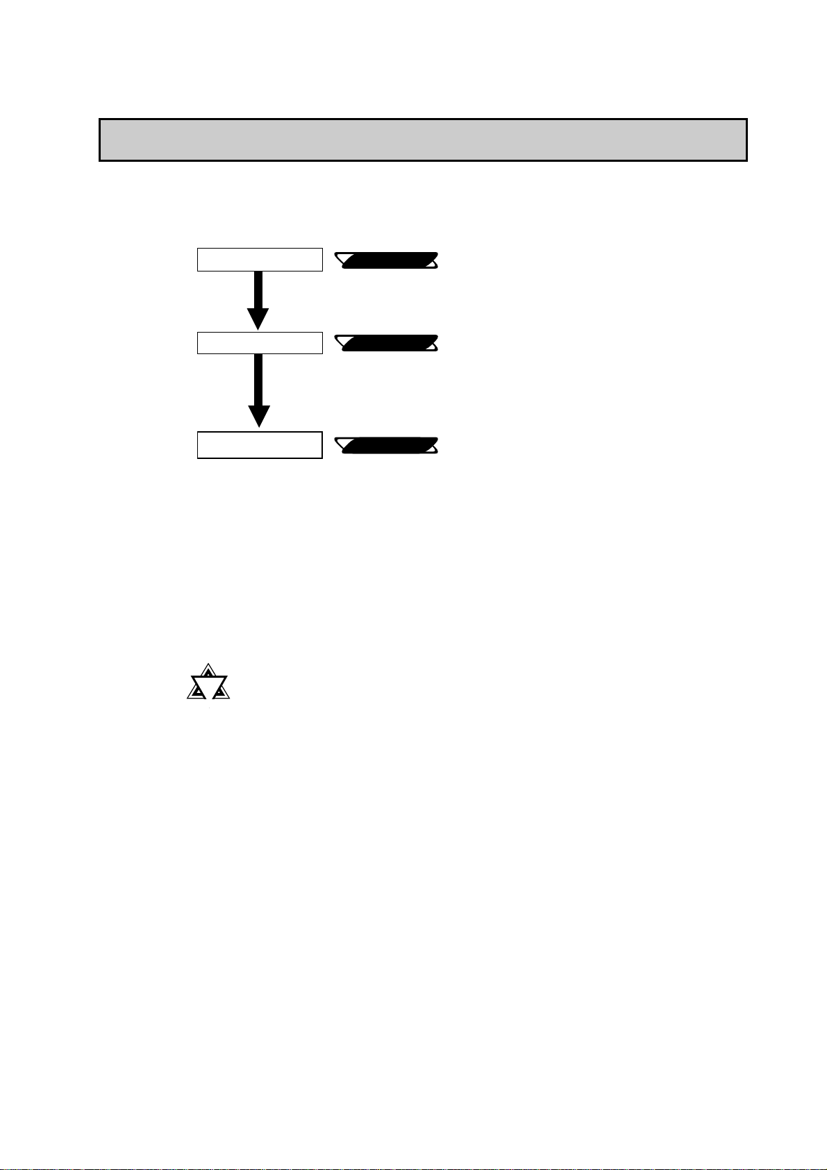
Prior To Using the PL
Prior To Using the PL
Prior to actual use, be sure to setup your PL as follows.
Turn PL ON
Setup System
Install the OS
Reference
Reference
Reference
4-3 Wiring the PL
Chapter 5 System Setup
OS maker’s Installation Manual.
After completing the hardware setup, before
any data or applications can be placed on the
drive, the OS (Windows or MS DOS, etc.)
must be used to initialize the HDD and create
partitions. For details concerning these procedures, refer to the OS maker’s installation
manual.
!!
!
!!
Important
• For system setup and OS installation, a PS/2 type keyboard is
necessary.
• When using Windows® NT4.0, be sure to install the PL-6700
Driver & Utility Disk’s Display Driver (For installation procedures, see the disk’s README files).
• For information on the PL-6700’s bundled utility software, see
the README files on the Driver & Utility Disk.
• Since the PL-6700’s hard disk drive (HDD) is a consumable
item, i.e. it has a definite usage lifetime, be sure to back up its
data frequently and perform regular maintenance.
PL-6700 43 Series User’s Manual xi

New PL-6700 Features
The PL-6700 series displays are equipped with the following features:
The Latest, High-Performance Architecture
Designed around the MMX Pentium®200(MHz) CPU, the PL utilizes the
type of high performance architecture that offers you superior compatibility.
Add to this unrivalled support of the Windows®95 / NT® and other operating
systems.
Bright 12.1" LCD with a Wide Viewing Angle
The PL’ s large 12.1-inch 800 x 600 dot LCD display is available with TFT
color, offering excellent visibility and brightness.
Preface
New PL-6700 Features
Note:
• Digital’s top of the line TFT color LCD model allows you to create detailed
and powerful visual images, with excellent brightness, a wide viewing
angle, and a display capable of 260,000 colors.
Easy Front Panel Installation
The PL is designed to be installed easily into the front of any panel or
device. It is also rugged enough for use in harsh, industrial environments,
such as those found in the factory automation industries and boasts an IP65f
rating.
High Resolution, Analog-Resistance-Film Touch Panel
Standard equipment with the PL is a high resolution 1024 × 1024 touch
panel. Also, the WindowsNT® 4.0 / Windows® 95 mouse emulation utilities
provide mouse-like functionality and pointer control.
Highly Expandable
For the easy enhancement of your PL unit, 4 ISA-bus expansion slots are
provided. (2 PCI slots are also available) These slots can accommodate both
Digital’s own optional boards as well as other commercially available
expansion boards.
Digital also offers a wide variety of optional products, such as an -5/-12V
DC power unit, DIM memory modules, etc. to name just a few.
PL-6700 43 Series User’s Manualxii
Preface
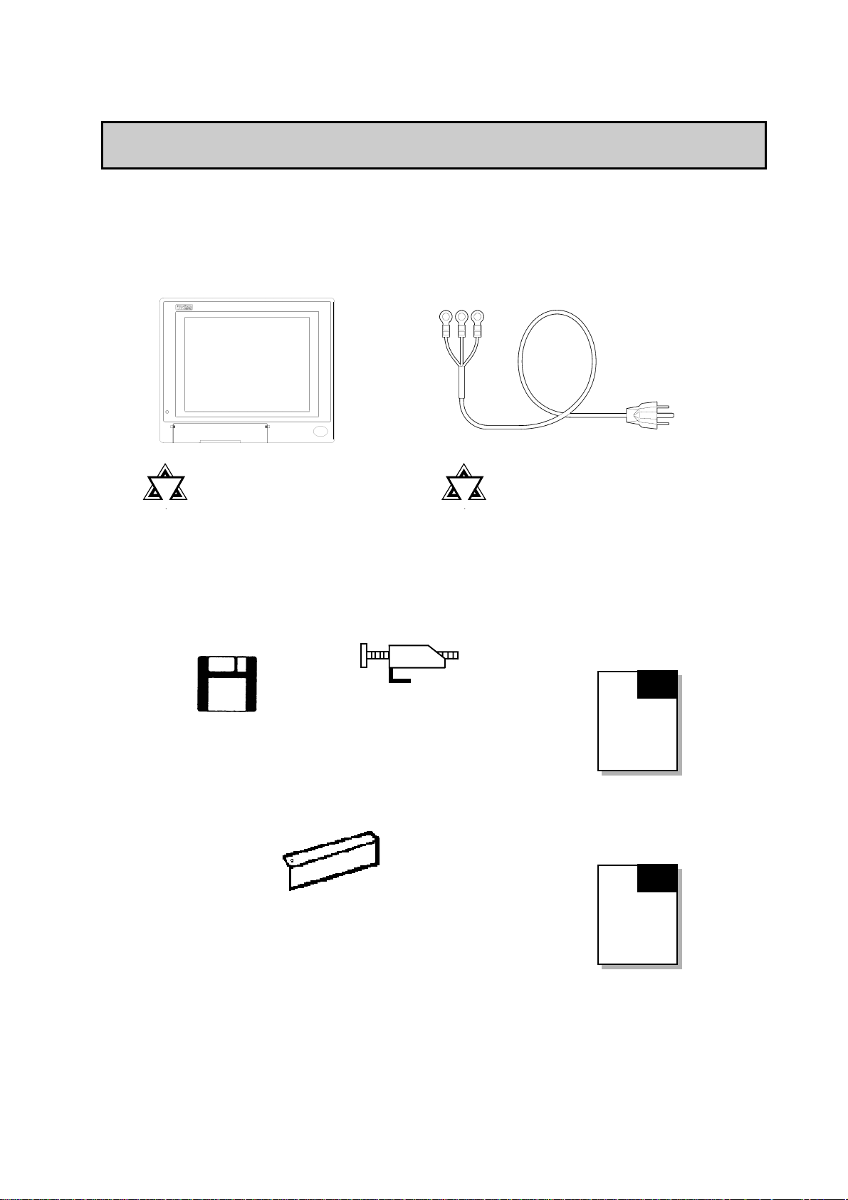
PL-6700 Unit
(PL-6700T)
PL Package Contents
The PL package should include the following items:
Power Cord
PL Package Contents
!!
!
!!
• Be careful when in-
Important
stalling the PL -6700 to
not damage the builtin HDD
PL- 6700
Floppy Disks (2)
Installation Brackets (8)
Angle Plate (1)
!!
!
!!
Important
• This cord is designed only for
100V use. Any other voltage
will require a different cable.
Panel Computer PL-6700
43 Series User’s Manual
(English)
PL-6700
43 Series
User’s
Manual
(English)
Panel Computer PL-6700
43 Series User’s Manual
(Japanese)
PL-6700
43 Series
User’s
Manual
(Japanese)
PL-6700 43 Series User’s Manual xiii
Symbol Information
Preface
Symbol Information
The list below describes the symbols used in this manual.
Symbol Description
!!
!
!!
Warning
!!
!
!!
Caution
!!
!
!!
Important
Note:
****
Reference
1) 2)
1) 2)
1) 2)1) 2)
Incorrect operation resulting from negligence of this
instruction may cause death or serous injury.
Incorrect operation resulting from negligence of this
instruction may cause injury or damage to equipment.
Failure to observe this instruction may cause abnormal
operation of equipment or data loss.
Provides hints on correct use, or supplementary
information.
Indicates useful or important supplemental information.
Indicates related (manual name, page number) information.
Indicates steps in a procedure. Be sure to perform these
steps in the order given.
PL-6700 43 Series User’s Manualxiv

Chapter 1Chapter 1
Chapter 1
Chapter 1Chapter 1
OverviewOverview
Overview
OverviewOverview
1. System Configuration
2. Options
3. PL Series Panel Types
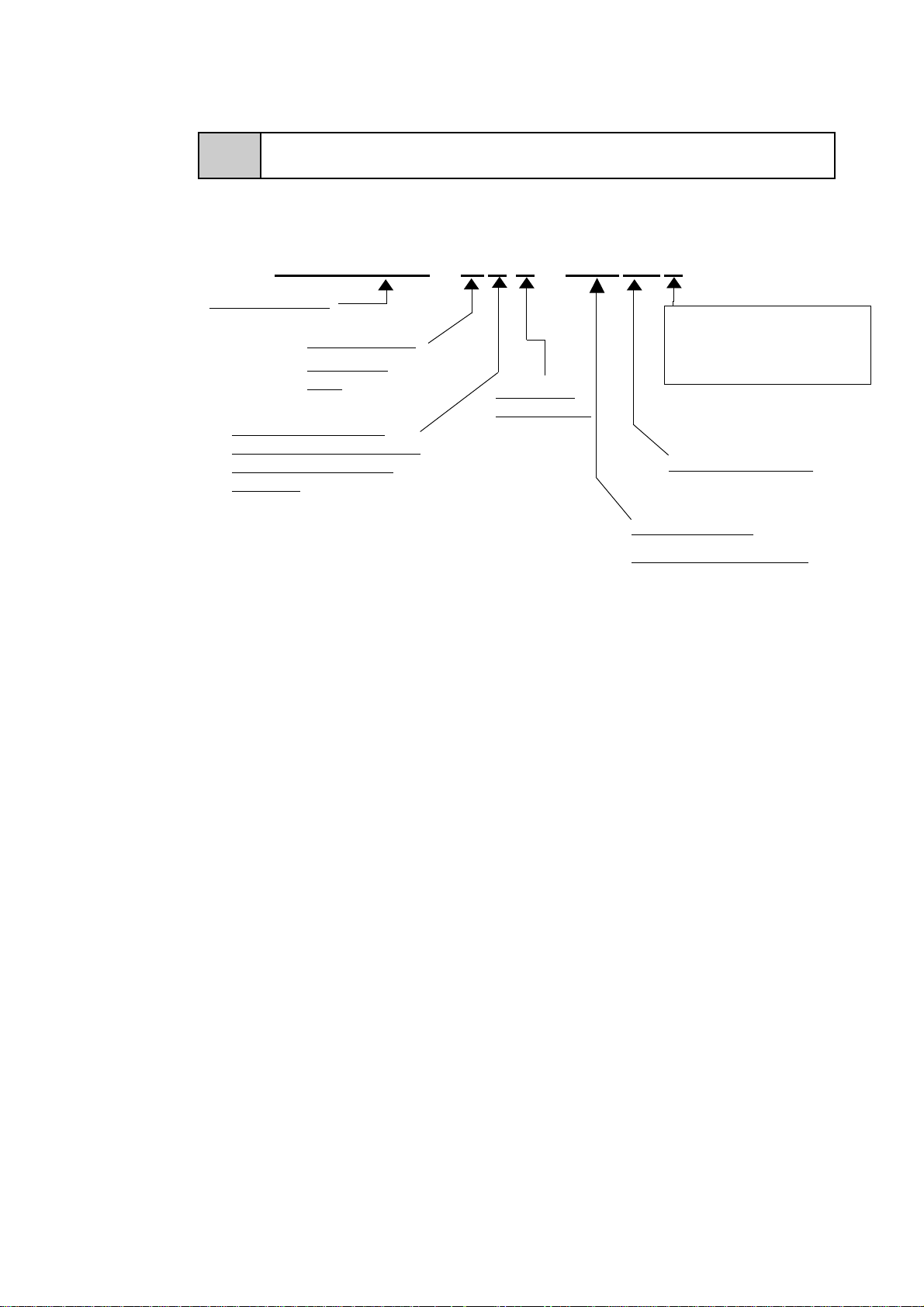
1-1 System Configuration
The following figure shows the peripheral devices that can be connected to
the PL.
Analog Resistance Film T ouch Panel
Display Unit (COLOR TFT)
Backlight Lamp (CFL type)
Inverter Unit
CRT
CD-ROM
drive
HDD(2.5”)
Peripheral
Devices
Printer
Keyboard
Mouse
Optional Unit(s)
Commercial
items
RS232C×3
Main Circuit Board
Slave
Adapter
ISA Slots (4) (2 PCI slots are also available)
Power Supply Unit
32MB RAM Memory
(standard)
DIMM sockets (2)
Power Supply Unit
DC 5V/12V
AC IN 85 to 132V
170 to 265V
• Boxes marked with a border represent optional items.
DC -5V/ -12V
IrDA I/F Unit
Inside Front
Maintenance Cover
Front Keyboard
Connector
Reset Switch
Front Mount
FD Unit
border represent User supplied items.
!!
!
!!
Important
• Boxes marked with a
• The figure above shows simply the internal data flow and the
PL’s peripheral connections, and may differ from the actual
layout used by the customer.
PL-6700 43 Series User’s Manual 1-1
1-2 Options
Chapter 1 - Overview
1-2 Options
The following table provides a list of optional products for the PL.
Expansion Options
Name
DIM Module PL-EM200 Main Memory Board
FDD Unit PL-FD100 PC/AT Compatible 3.5” FDD unit
IDE Slave
Adapter
IrDA Unit (under
development)
-5V/-12V Power
Unit
CD-ROM Drive
Unit
Model
number
PL-SA100 Adapter used for attaching an IDE (ATAPI) compliant CD-ROM
drive (DC power cord included)
PL-IR100 IrDA (Ver. 1.0) compatible infrared data transmission module.
PL-PW100 Provides –5V and –12V power to expansion slots. Can provide a
total of 200mA of current (sum of all four slots).
PL-DK200 IDE (ATAPI) compliant CD-ROM drive unit
(Connection cable is included in unit)
Description
Accessories
Name
Screen
Protection Sheet
Model
number
PL-CS100 Disposable overlay sheets for display face protection and
stain resistance. Touch panel senses User’s touch through
sheet.
Description
Maintenance Options
Name
Mounting
Brackets
Moisture
Resistant Gasket
HDD Unit
Full Sized Cover PL-FC100 Attached when ISA bus full-sized board is installed in
*1
Model
number
GP070AT00-MS
PL-WS100 Used to prevent moisture from entering into the PL’s case
PL-HD100 Built-in 2.5” HDD unit
Used to install the PL into a panel or cabinet. Same as
original equipment brackets.
from the front face. Same as original equipment gasket.
expansion slot.
Description
Software Options
Name
*2
TT-WIN/95
TT-WIN/NT
*2
*1 Since the PL’s hard disk drive (HDD) is a consumable item, i.e. it has a definite usage
lifetime, be sure to back up its data frequently and perform regular maintenance.
*2 Depending on the customer’s OS (Operating System) one of these drivers will be
required to allow this type of touch operation. Please contact your local PL distributor for ordering details.
Model
number
Description
Touch Panel mouse driver that provides mouse-like
operability to the PL’s touch panel. (for Windows 95 OS)
Touch Panel mouse driver that provides mouse-like
operability to the PL’s touch panel. (for Windows NT OS)
PL-6700 43 Series User’s Manual1-2
Chapter 1 - Overview
1-3 PL Series Code Name Explanation
Model Number:
P L 6 7 00 - T 4 3 - HU 01 x
PL-6700 series
1-3 PL Series Panel Types
Display T ype:
TFT Color
LCD
This unit is a (c)UL
recognized, CE marked
and EMC Compliant
product.
F: FDD Installed
(no char.) : No FDD
PL-6700’s
revision no.
HDD Revision No.
Hard Disk Type
HU : OS Not Installed.
PL-6700 43 Series User’s Manual 1-3

MEMO
Chapter 2Chapter 2
Chapter 2
Chapter 2Chapter 2
SpecificationsSpecifications
Specifications
SpecificationsSpecifications
1. General Specifications 4. PL External Features
2. Performance Specifications 5. PL Dimensions
3. Interface Specifications
2-1 General Specifications
1. Electrical Specifications
Operating Voltage 85V AC to 132VAC / 170V AC to 265V AC 50/60 Hz
Power Consumption Less than 150W
Allowable Voltage
Drop
Voltage Endurance
Isolation Resistance
less than 20ms
1500V AC at 20mA for 1 minute (between the live wire and
the grounding (FG) terminal)
Greater than 10MΩΩΩΩ at 500V DC (between the live wire and
the grounding (FG) terminal)
2. Environment Specifications
Operating
Temperature
Operating Humidity 30 to 85% RH (no condensation)
Storage Conditions -10 to 60o C/ 30 to 85% RH (no condensation)
Operating
Atmosphere
Noise Immunity
(via noise simulator)
Electrostatic Voltage
Endurance
Vibration Endurance
Rating
(with front panel closed)
*1 The front face of the GP unit, installed in a solid panel, has been tested using conditions equivalent to the
standard shown in the specification . Even though the GP unit’s level of resistance is equivalent to the
standard, oils that should have no effect on the GP can possibly harm the unit. This can occur in areas
where either vaporized oils are present, or where low viscosity cutting oils are allowed to adhere to the
unit for long periods of time. If the GP’s front face protection sheet becomes peeled off, these conditions
can lead to the ingress of oil into the GP and separate protection measures are suggested. Also, if nonapproved oils are present, it may cause deformation or corrosion of the front panel’s plastic cover.
Therefore, prior to installing the GP be sure to confirm the type of conditions that will be present in the
GP’s operating environment.
If the installation gasket is used for a long period of time, or if the unit and its gasket are removed from
the panel, the original level of the protection cannot be guaranteed. To maintain the original protection
level, you need to replace the installation gasket regularly.
*1
o
5 to 40
Free of corrosive gas
Noise Voltage: 1500Vp-p
Pulse Duration: 50ns, 500ns, 1µµµµs
4kV
2G: 10 to 25Hz applied in X, Y, and Z directions for 30 minutes
each (0.5G when using HDD unit, 1.0G when using FDD)
Equivalent to IP65f (JEM1030)
C (with HDD and FDD not installed, 0 to 40
o
C)
PL-6700 43 Series User’s Manual 2-1
2-2 Performance Specifications
Chapter 2 - Specifications
!!
!
!!
Important
• When using any of the PL’s optional devices, be sure to check
that device’s specifications for any special conditions or
cautions that may apply to its use.
• When using a full sized expansion board, be sure to check its
dimensions and shape, since they will affect the board’s environment specifications, such for vibration, etc.
3. Dimensions
External Dimensions
Weight
D ime n sions ( w/c ove r)
346W x 287H x 174D (mm)
less than 7.4kg (with HDD and FDD installed)
419W x 287H x 174D (mm)
2-2 Performance Specifications
1. Performance Specifications
CPU
DRAM
BIOS
Secondary Cache
Graphics
Touch
Panel
Front
and
Rear
Interfaces
Type
Resolution
Interface
Serial
Printer
Keyboard
Mouse
MMX Pentium® (200MHz) (Intel Corporation)
Equipped with 32MB (2 DIMM sockets – max. of 64MB)
AWARD PC/AT Compatible
512K
SVGA (800 x 600 dots)
VESA 16 colors/256 colors/32K colors/64K colors
Analog Resistant Film
1024 x 1024
COM4 (uses Mouse Emulator)
RS-232C
(w / FIFO)
Centronics Standard (DB 25-pin female connector)
PS/2 Interface (mini DIN 6 pin female connector) side & front
PS/2 Interface (mini DIN 6 pin female connector) side
COM1 D-Sub 9 pin (male)
COM2 D-Sub 9 pin (male)
COM3 D-Sub 9 pin (male)
2-2
RGB Output
Disk I/F
Analog RGB Output
FD Unit Front Access 2 modes
IDE 2.5 inch HDD I/F
PL-6700 43 Series User’s Manual
Chapter 2 - Specifications
2-2 Performance Specifications
!!
!
!!
Important
2. Display Functions
• Be aware that not only does the Hard Disk have a fixed lifetime, but that accidents can always occur. Therefore, be sure
to back up your Hard Disk’s data regularly, or prepare another
Hard Disk unit that can be used for backup.
• The Hard Disk lifetime value in this manual is for reference
purposes only. At 25 °C, it is approximately five years or
20,000 operating hours, whichever comes first. Unforeseen
factors (environmental changes, etc.) may cause it to actually
be shorter.
PL6700T
Display Type
Pixel Density
Effective Display Area
Dot Pitch
Display Colors
Contrast Adjus t m e nt
Backlight
*1
TFT Color LCD
800 x 600 (pixels)
247W x 185H (mm)
0.3 x 0.3 (mm)
260,000 colors
Not Possible
Replaceable ( under normal temperatures and humidity,
lifetime = 25,000 hours )
!!
!
!!
Important
1st Slot (ISA) 163 x 122 (mm)
2nd Slot (PCI/ISA) 163 x 122 (mm)
3rd Slot (PCI/ISA) 250 x 122 (mm)
4th Slot (ISA) 250 x 122 (mm)
Note:
*1 The PL’s backlight should be replaced by only an authorized
repairman. For information about this service, please contact
your nearest authorized distributor.
3. Expansion Slots
Board Size Power Supply
5V : 4A
12V : 1.5A
(total for all 4 slots)
• Slots 2 and 3 can be used for either PCI or ISA cards.
• The distance (pitch) between the 1st and 4th slots and their adjacent slots
is 20mm. The pitch between the 2nd and 3rd slots is 25mm.
• Slots 3 and 4 can support full-sized boards. However, when using a fullsized board, the top edge of the board will extend beyond the standard
case. In this case the optional full-sized cover is recommended.
Reference
3-2-5 Installing an Expansion Board
PL-6700 43 Series User’s Manual 2-3

2-3 Interface Specifications
2-3 Interface Specifications
1. Printer Interface (LPT1)
Chapter 2 - Specifications
D-sub 25 Pin (Female)
13 12 11 10 9 8 7 6 5 4 3 2 1
25 24 23 22 21 20 19 18 17 16 15 14
Note:
O.D : Open Drain
T.S : 3 state I/O
TTLIN : TTL Input
!!
!
!!
Important
• The software protection Key used by some software applications, if left attached to the PC while a “ Windows Printing
System ” printer or a “ Windows ” type cable are used (for bidirectional commnication), there is a possibility that the protection Key will be damaged. Therefore, be sure to remove
this Key before performing printing.
Pin
No.
Signal
Name
1STROBEOUT*1O.D 14 AUTOFD OUT O.D
2 DATA0 OUT*1T.S 15 ERROR IN TTLIN
3 DATA1 OUT*1T.S 16 INIT OUT O.D
4 DATA2 OUT*1T.S 17 SLCTIN OUT O.D
5 DATA3 OUT*1T.S 18 GND
6 DATA4 OUT*1T.S 19 GND
7 DATA5 OUT*1T.S 20 GND
8 DATA6 OUT*1T.S 21 GND
9 DATA7 OUT*1T.S 22 GND
10 ACKNLG IN TTLIN 23 GND
11 BUSY IN TTLIN 24 GND
12 PE IN TTLIN 25 GND
13 SLCT IN TTLIN
Direction
Elect.
Specif.
Pin
No.
Signal
Name
Direction
Elect.
Specif.
2-4
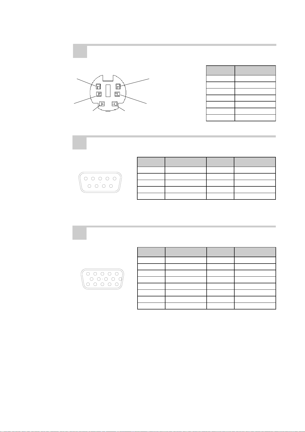
2. Keyboard Interface
Mini - DIN 6 pin (Female)
6
4
2
Recommended Keyboard: Any PS-2 type keyboard
1
5
3
*1 Output: The Input and Output settings used will depend the BIOS set up screen settings
used.
PL-6700 43 Series User’s Manual
(The PL’s front and side
connectors are the same)
Pin No. Signal Name
1 KEY DATA
2NC
3GND
4+5
5 KEY CLK
6NC
SHIELD GND
Chapter 2 - Specifications
3. Mouse Interface
2-3 Interface Specifications
Mini - DIN 6 pin (Female)
Pin No. Signal Name
6
5
1 Mouse DATA
2NC
3GND
4+5
4
2
1
3
5 Mouse CLK
6NC
SHIELD GND
4. RS-232C Interface (COM1/COM2/COM3)
D-sub 9 pin (Male)
1 2 3 4 5
6 7 8 9
Screw Size: (4-40): Inch Type
Pin No. Signal Name Pin No. Signal Name
1CD6DSR
2RXD7RTS
3TXD8CTS
4DTR9 RI
5GND
5. CRT Interface (Video)
Mini - D-sub 15 pin
(Female)
5 4 3 2 1
10 9 8 7 6
15 14 13 12 11
Pin No. Signal Name Pin No. Signal Name
1R9NC
2G10GND
3B11NC
4 NC 12 RESERVE (NC)
5 GND 13 H.SYNC
6 R-GND 14 V.SYNC
7 G-GND 15 RESERVE (NC)
8B-GND
PL-6700 43 Series User’s Manual 2-5
2-4 PL External Features
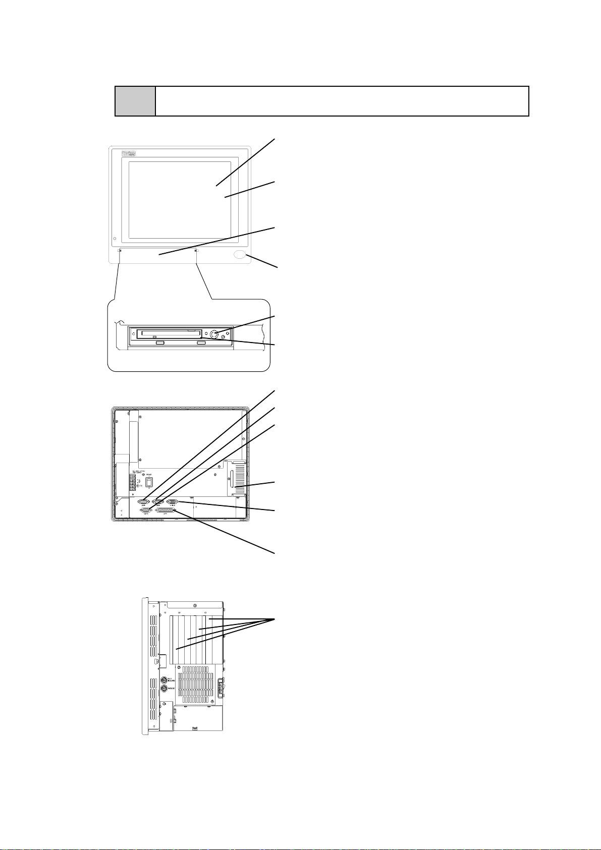
2-4 PL External Features
With cover opened:
(Drawings shown here are for
the PL-6700T unit)
Chapter 2 - Specifications
Display Area
Display output area. The built-in SVGA controller
supports PC compatible architecture.
T ouch Panel
This high-resolution analogue touch panel allows you to
configure a keyboard-less system.
Front Maintenance Cover
Open this cover to connect the optional FDD unit or
memory card interface unit.
IrDA
When the optional PL-IR100 is installed, infra-red signals are sent and received by this unit.
Keyboard Connector
A PS/2 compatible keyboard is connected here.
Floppy Disk Insertion Slot
This slot is used if the optional FDD unit or memory
card interface is installed.
RS-232C Connector (COM1)
RS-232C Connector (COM2)
RS-232C Connector (COM3)
RS-232C interfaces (DB 9-pin male connectors), which
allow communication with other computers or connection to peripheral devices.
HDD Cover
When an HDD is installed, this cover is removed.
Analog RGB Connector
A PC/AT compatible multi-scan monitor can be connected here.
Printer Connector (LPT1)
Centronics standard interface (DB 25-pin female connec-
tor), which connects a parallel device, such as a printer
(supports ECP/EPP)
Expansion Slots
A variety of expansion boards, both Digital’s and
other makers, can be installed here.
“3-1 Available Options andExpansion Boards”
The PL-6700T is equipped with four (4) expansion
slots. Seen from the front of the unit, these slots are
numbered 1, 2, 3 and 4.
2-6
PL-6700 43 Series User’s Manual
Chapter 2 - Specifications
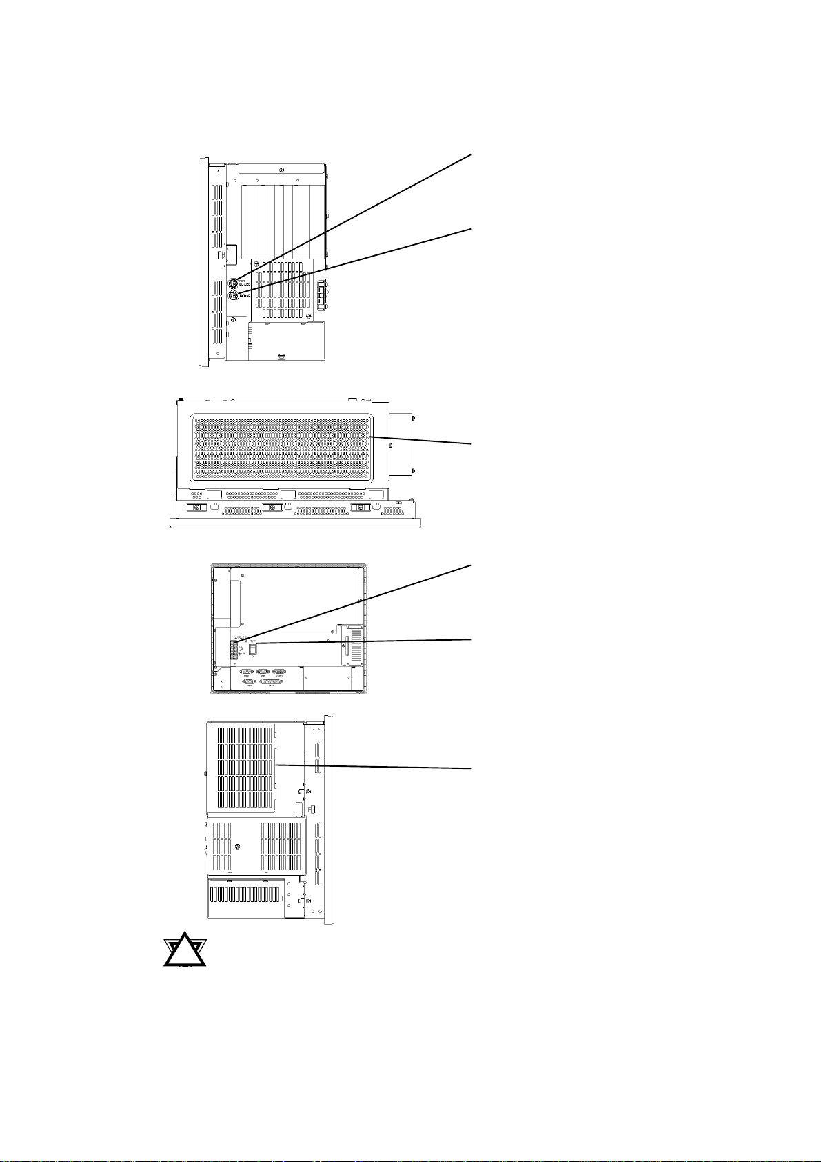
2-4 PL External Features
Keyboard Connector
A PS/2 compatible keyboard can be
connected here.
Mouse Connector
A PS/2 compatible mouse can be connected here.
Rear Maintenance Cover
Remove this cover to install the optional DIM module, or an expansion
board.
Power Input Terminal Strip
Connect the 100V/240V AC power
cord here.
Power Switch
Use this switch to turn the PL’s power
ON or OFF.
Half Cover
When attaching the optional DIM
module or other optional expansion
boards, you will need to remove this
cover.
• When attaching peripheral units to the PL, be sure the PL’s
!!
!
!!
Warning
PL-6700 43 Series User’s Manual 2-7
power cord is disconnected from the main power supply.
• To avoid an electrical shock, be sure to disconnect the PL’s
power cord from the power supply before connecting the
cord’s power terminals or any peripheral devices to the PL.

2-5 PL Dimensions
2-5 PL Dimensions
1. PL-6700T General Dimensions
Chapter 2 - Specifications
Note:
287
• For detailed dimension information, please contact your local GP distribu-
tor.
Unit: mm
(excluding
projections)
346
Effective
Display Area
(W) x (H)
Front Face
174
13
Side View Side View
(Opposite Side)
271
2-8
PL-6700 43 Series User’s Manual
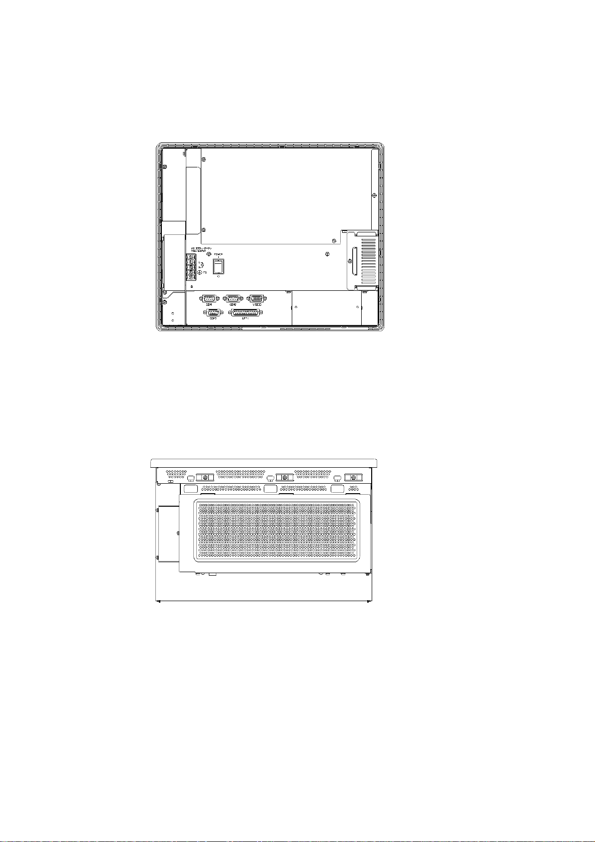
Chapter 2 - Specifications
2-5 PL Dimensions
Rear Face
Top Face
330
PL-6700 43 Series User’s Manual 2-9
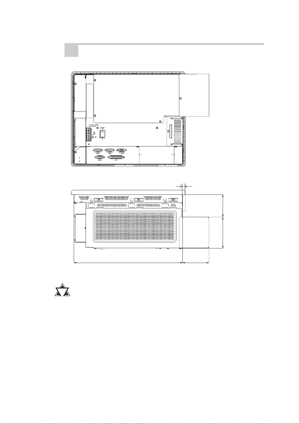
2-5 PL Dimensions
2. Full Sized Cover Attachment Dimensions
Chapter 2 - Specifications
Rear Face
!!
!
!!
Important
8
67
Top Face
94
330
80
• When using a full-sized board and the PL’s full-sized cover
(PL-FC100), be sure that the PL is mounted in its atatchment
panel/cabinet before starting this work. The PL’s full sized
board and cover cannot be attached first and then the unit
installed, due to size differences.
2-10
• When using a full sized expansion board, be sure to check its
dimensions and shape, since they will affect the board’s environment specifications, such for vibration, etc. The specifications given in this manual are without the full-sized cover
attached. Please contact your nearest Pro-face dealer when
using a full-sized expansion board.
PL-6700 43 Series User’s Manual
Chapter 2 - Specifications
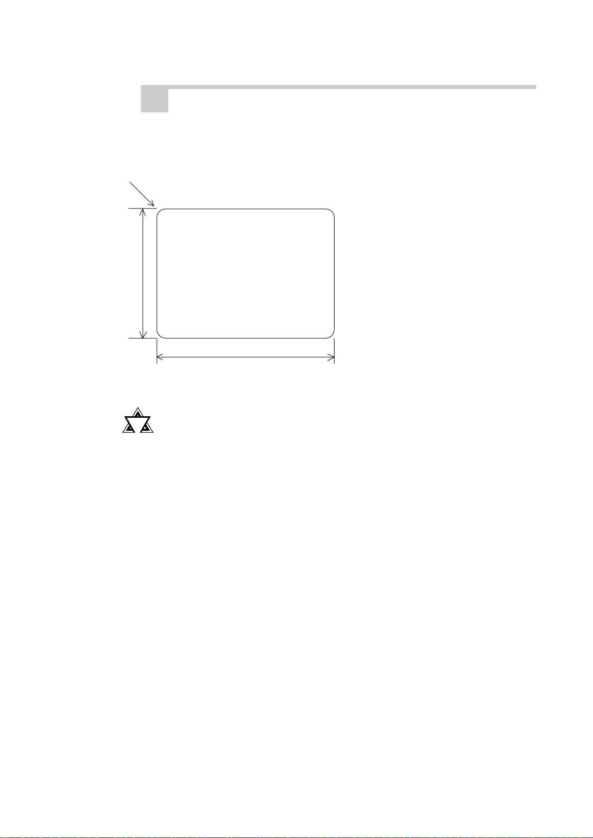
3. Installation Slot Dimensions
(Unit: mm)
4-R2
272.0+ 0.5
- 0
2-5 PL Dimensions
!!
!
!!
Important
331 + 0.5
- 0
• Be sure the thickness of the panel is from 1.6 to 10 mm.
• To insure that the PL’s water resistance is maintained, be sure
to install the PL into a panel that is flat and free of scratches
or dents.
PL-6700 43 Series User’s Manual 2-11
 Loading...