

Digital Equipment Pro-face FP2500-T41 User Manual
FP2500-T41
User Manual
Digital Electronics Corporation

Preface
Thank you for purchasing Digital’s TFT type color display panel, the 'FP2500-T41'
(hereafter referred to as the FP unit).
The FP unit is a TFT type color liquid crystal display monitor for IBM-PC compatible
personal computers (VGA mode).
Please read this manual completely to insure the correct use and complete understanding of the FP unit's functions. The FP's analog interface is designed for use with
standard VGA mode. Please be aware that this unit may not be able to be connected
with nonstandard VGA modes. For more details, please refer to this manual's "PC
Connectivity Notes" section.
The term FP2500-T41 refers to the following unit:
FP2500-T41-24V (DC 24V type)
<Note>
1) It is forbidden to copy the contents of this manual, in whole or in part, except for
the user's personal use, without the express permission of the Digital Electronics
Corporation of Japan.
2) The information provided in this manual is subject to change without notice.
3) This manual has been written with care and attention to detail; however, should you
find any errors or omissions, please contact Digital Electronics and inform them of
your findings.
4) Please be aware that Digital Electronics is not responsible for any damages resulting from the use of our products, regardless of article 3 above.
5) Specifications set out in this manual are for overseas products only , and, as a result,
some differences may exist between the specfications given here and the Japanese
ones.
All Company/Manufacturer names used in this manual are the registered trademarks of
their respective companies.
© 2001, Digital Electronics Corporation
FP2500-T41 User Manual i
For the Safe And Correct Use of this Unit:
This manual describes safety instructions for correct use of the FP unit. Please keep this
manual close at hand, and refer to it when necessary .
The following symbols are used throughout this manual to ensure the safe use of the FP
unit. Please make sure to follow all instructions given since they explain important safety
points.
This mark warns of a situation that could either seriously
W arning
Caution
injure a person or lead to death if the instruction is ignored
and/or the unit is used incorrectly.
This mark warns of a situation that could either injure a
person or damage property if the instruction is ignored and/
or the unit is used incorrectly.
Other Symbols Used In This Manual
The list below describes the symbols used in this manual.
Explains a situation that requires a moderate amount of caution.
Indicates a word or phrase that has an additional explanation.
*1
1),2)
A reference point. Describes the word or phrase marked by the asterisk (*) and the corresponding number.
Reference pages on related topics.
Operational steps. Please follow these numbered steps in order to
perform the desired operation.
ii FP2500-T41 User Manual

W arning
Safety Instructions
For the safe use of this unit, be sure to follow these guidelines:
Because of the ever present danger of electrical shock, be sure to unplug the power cable
from the FP unit before plugging the cable's other end into the wall.
Do not use power in excess of the unit's specified voltage range since it may cause a fire or
electric shock.
Because the FP unit contains high voltage parts, an electric shock can occur when disassembling the unit. Therefore, please be sure to always unplug the unit before disassembling
it.
Do not modify the FP unit in any way , since it may cause a fire or electric shock.
When changing the backlight, be sure to turn off the unit's power first, in order to prevent an
electric shock.
Do not use touch panel keys to perform life-threatening or vitally important safety functions.
Use separate mechanical switches for such keys.
If substantial amounts of metallic dust, water or liquids enter the FP unit, turn off the power
supply immediately , unplug the power cord, and contact your local FP distributor.
When installing the FP unit, be sure to follow the instructions given in “Chapter 3. Installation
and Wiring," to insure it is done correctly .
Do not use the FP in an environment with flammable gas since it may cause an explosion.
FP2500-T41 User Manual iii
Caution
Safety Instructions
For the correct use of this unit, please follow these guidelines:
Do not press the screen's touch surface too strongly with either your finger or a hard
object, since the touch surface may be damaged.
When the surface of the display screen becomes dirty or smudged, clean the display with
a cloth soaked in a neutral detergent. Do not use paint thinner or organic solvent.
Do not press on the touch panel's face with sharp objects, such as a mechanical pencil or
screwdriver, since it might damage the LCD panel.
A void using or storing the FP in direct sunlight, excessively dusty or dirty environments, or
where chemicals or their vapors are present in the air.
A void restricting the FP's natural ventilation, or storing and using the FP in an environment
that will increase the FP's internal temperature.
Please avoid using the FP in areas where sudden, large changes in temperature may occur .
These changes can cause condensation to form inside the unit, possibly causing an accident.
Notes on the FP's Liquid Crystal Display (LCD)
The FP's LCD contains a strong irritant. If the panel is ever cracked and the LCD's liquid
contacts your skin, be sure to wash it with running water for at least 15 minutes. If any of
this liquid should enter your eye, be sure to flush the eye with running water for more than
15 minutes, and see a doctor immediately .
The current brightness of the LCD screen will depend on the screen's current display and
the LCD's contrast adjustment. Any brightness variations that result are normal for LCD
displays.
There are minute grid-points on the LCD surface. These points are not defects.
Sometimes crosstalk (shadows appearing on extended display lines) will appear on the
display . This phenomenon is a common attribute of LCD's and is not a defect.
The displayed color will look different when viewed from an angle outside the specified
view angle. This is also normal.
Displaying a single screen image for long periods of time can cause an afterimage to
remain. To correct this, turn the unit OFF for 5 or 10 minutes, then ON again. This
phenomenon is a common attribute of the LCD's, and not a defect. T o prevent this effect,
you can:
- use the Display OFF feature, if the same image is to be displayed
for a long period of time.
- change the screen display periodically to prevent the displaying of a
single image for a long period of time.
iv FP2500-T41 User Manual

T able of Contents
Preface ........................................................................................................................i
For the Safe and Correct Use of this Unit..................................................................ii
W arning: Safety Instructions ....................................................................................... iii
Caution: Safety Instructions ........................................................................................iv
Table of Contents ........................................................................................................v
When Connecting to a PC...........................................................................................vii
FP2500-T41 Features..................................................................................................viii
Package Contents ....................................................................................................... ix
UL/c-UL (CSA) Application Notes ...........................................................................x
CE Making Notes........................................................................................................x
Chapter 1—Introduction
1-1 Connecting the FP to a PC .................................................................................. 1-1
1-2 Optional Equipment ...............................................................................................1-2
Chapter 2—Specifications
2-1 General Specifications (For DC24V) ................................................................... 2-1
1 Electrical Specifications ..............................................................................................2 - 1
2 Environmental Specifications .....................................................................................2- 1
3 Structural Specifications.............................................................................................2-2
2-2 Functional Specifications (For DC24 V) ..........................................................................2-3
2-3 Interface Specifications
1 Analog RGB Interface .................................................................................................2 -4
2 Serial Interface ............................................................................................................2-6
3 USB Interface ..............................................................................................................2-7
2-4 Cable Diagrams ...................................................................................................2-8
1 Pin Connections for the RGB Interface Cable............................................................2-8
2 Pin Connections for the SIO Interface Cable .............................................................2- 9
3 Pin Connections for the USB Interface Cable ...........................................................2-9
2-5 Names and Functions of FP Parts.............................................................. 2-10
2-6 Flat Panel (FP) Dimensions........................................................................ 2-11
1 External Dimensions (DC24V) ............................................................................. 2-11
2 Installation Brackets ........................................................................................... 2-12
3 FP Installation Dimensions ................................................................................. 2-12
(For DC24V) ...........................................................................2-4
FP2500-T41 User Manual v

Chapter 3—Installation and Wiring
3-1 Installation .................................................................................................................3-1
3-2 Wiring........................................................................................................................3-5
1 Power Cable Connection ................................................................................................... 3 - 5
2 Precautions: Connecting the Power Supply...................................................................... 3-6
3 Precautions: Grounding .....................................................................................................3-7
4 Precautions: Input/Output Signal Lines............................................................................ 3-7
3-3 Operation Mode Setup and Display Positioning .......................................................3-8
1 Operation Mode Setup and Adjustment ..............................................................3-8
2 Front LED Option Mode Display .....................................................................................3-9
3 Display Position Compensation by OSD..........................................................................3-10
Chapter 4—Touch Panel Commands
4-1 Command List..........................................................................................................4- 1
4-2 Boot-up Initialization ................................................................................................4-2
4-3 Touch Interface Data ..............................................................................................4-3
4-4 Touch Panel Commands..........................................................................................4-5
Chapter 5—Touch Panel Communication Programs
5-1 Bundled Software.................................................................................................... 5-1
5-2 Operation Environment............................................................................................5-2
5-3 T ouch panel Input Drivers....................................................................................... 5-3
1 FP ATPH.EXE (Touch Panel Handler) ............................................................................... 5 - 3
2 FPCALIB.EXE (T ouch Panel Data Calibration) ................................................................ 5-7
Chapter 6—Troubleshooting
6-1 Troubleshooting........................................................................................................ 6-1
1 Possible Device Problems ................................................................................................ 6-1
2 No Display........................................................................................................................ 6-2
3 T ouch Panel Does Not Work............................................................................................ 6-4
Chapter 7—Maintenance
7-1 Regular Cleaning .....................................................................................................7-1
1 Cleaning the Display ........................................................................................................ 7-1
2 Installation Gasket Check/Replacement ........................................................................... 7 - 1
7-2 Periodic Check Points .............................................................................................7-2
7-3 Replacing the Backlight ...........................................................................................7-3
INDEX.............................................................................................i - iv
vi FP2500-T41 User Manual
When Connecting to a PC
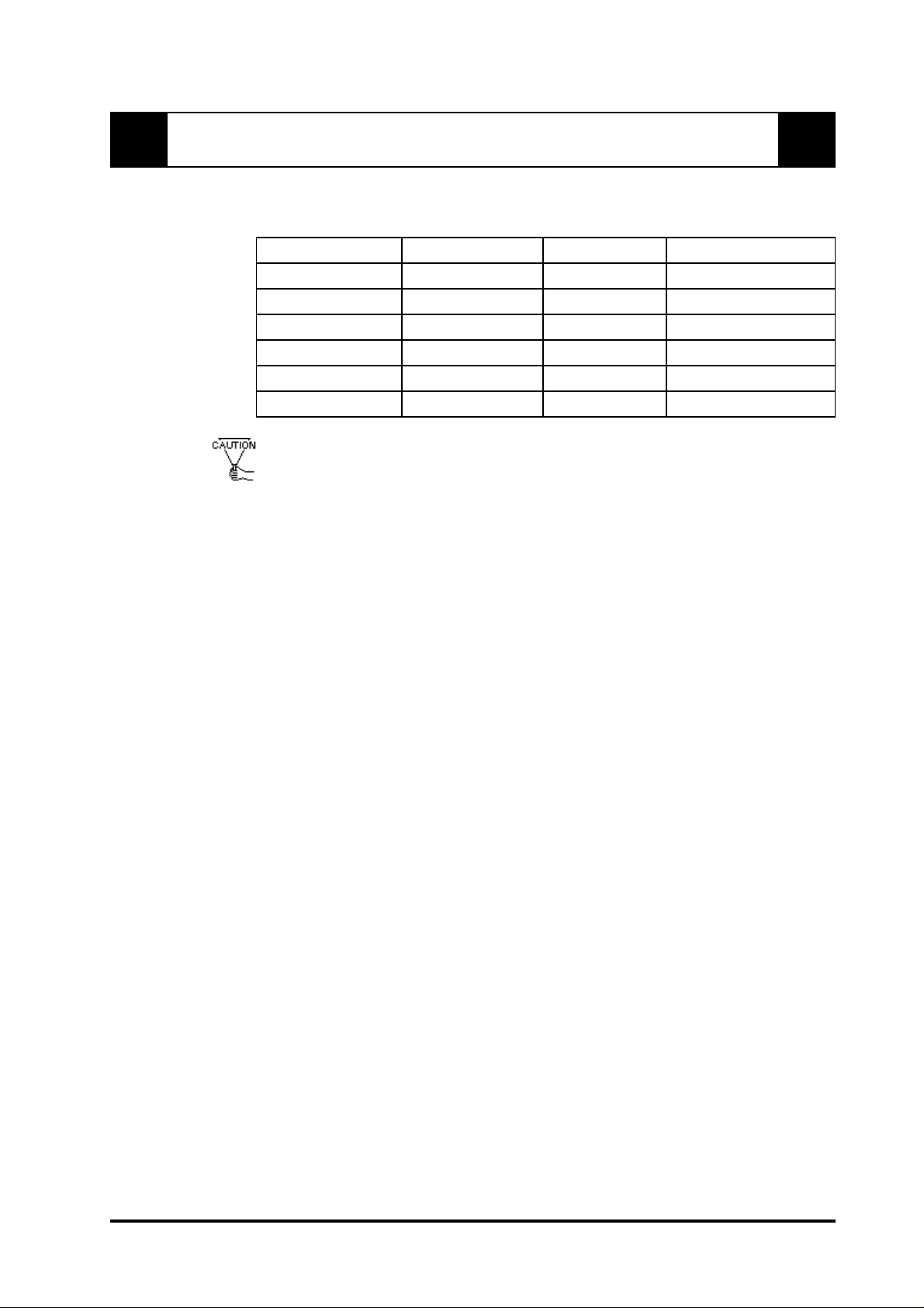
The FP unit's analog interface is designed for standard VGA mode. The number of dots
(pixels) displayed are as follows:
Siz e H Sync. V Sync. Dot Clock Ra nge
640 X 480 31.469± 1 K Hz 60±1 Hz 25.175MHz± 1%
640 X 400 24.827± 1 K Hz 56±1 Hz 21.053MHz± 1%
640 X 400 31.469± 1 K Hz 70±1 Hz 25.175MHz± 1%
640 X 350 31.469± 1 K Hz 70±1 Hz 25.175MHz± 1%
720 X 400 31.469± 1 K Hz 70±1 Hz 28.322MHz± 1%
720 X 350 31.469± 1 K Hz 70±1 Hz 28.322MHz± 1%
• Changeover from horizontal 720 pixels to 640 pixels is done via DIP switch.
• When the horizontal 720 pixel signal is input;
- VGA Graphic & T ext mode displays 640 pixels only and 80 pixels are not
displayed.
- VGA Graphic mode displays all pixels but images may be cut off if they do
not match the sampling.
• With vertical 350 pixels, 400 pixels, including 50 pixels at the top and at the
bottom of the screen will be enlarged and displayed at 480 pixels (1.2 times).
• When the unit is used in VGA text mode, the far right side's 80 dots are
not displayed.
• The display mode is designated using dip switch SW1-4.
Some types of VGA equipment may not be within the ranges specified above, and, therefore,
cannot be connected to the FP.
Also, if the user changes his PC's VGA board, there is the possiblity that the new board
may not be able to be connected to the FP.
FP2500-T41 User Manual vii

FP2500-T41 Features
The features of the FP2500-T41 are as follows.
High Quality TFT Color LCD Display
This unit is equipped with a 10.4 inch TFT type color LCD. Its superior brightness and
wide viewing angle, not found in ordinary laptop type TFT LCD's, widens your scope of
applications.
The screen's maximum resolution is 640 x 480 pixels, and can display 260,000 colors.
Easy Installation In User’s Cabinets and Panels
The FP2500-T41's slim, lightweight, and compact design make installation a snap. It
was designed specifically for use as your IA (Industrial Automation) or OA (Office
Automation) system monitor. The flat, front panel provides protection equivalent to the
rigorous IP65F standard, and, even without its optional protective cover, the front panel
is highly resistant to both water and dust.
Panel can be used as a VGA Display
Since the FP2500-T41 is equipped with an analog RGB interface, it can be connected
to any PC with standard VGA mode. (The PC's clock frequency , however , must be
within the standard range)
Easy to use Built In Touch Panel
The FP2500-T41's built in touch panel is standard equipment, allowing touch panel data
to be output to a host PC via input/output commands and an RS-232C cable and USB
cable. This is perfect for systems requiring both touch panel operation and data monitoring.
viii FP2500-T41 User Manual
Package Contents
The FP's packing box contains the items listed below . Please check to be sure each is
included and is not damaged.
FP unit (FP2500-T41-24V)
Installation Gasket (1)
FP2500/2600
User Manual(Contained in plastic case)
User Manual
Installation Brackets (4)
3.5 inch floppy disk
(Contains T ouch Panel programs) Installation Guide (1)
These items have all been carefully packed with special attention to product quality .
However, should you find anything damaged or missing, please contact your local
distributor immediately for prompt service.
FP2500-T41 User Manual ix
FP2500-T41/FP2600-T41
Installation
Guide

UL/c-UL (CSA) Application Notes
The FP2500-T41-24V is a UL/c-UL (CSA) listed product. (UL file No.E182139)
This unit conforms as a product to the following standards:
UL508 Industrial Control Equipment
UL1604 Electrical Equipment for use in Class 1 & 2 - Division 2, or Class 3 Hazardous
Locations.
CAN/CSA-C22.2, No. 1010-1
MESUREMENT AND CONTROL EQUIPMENT
(Safety requirements for electrical equipment for mesurement and laboratory use)
FP2500-T41-24V(UL Registration Model: 30B0003-01)
<Cautions>
The FP must be used as a built-in component of an end-use product.
This unit should be installed in the front face of a metal panel.
If this unit is installed so as to cool itself naturally , be sure to install it in a vertical panel.
Also, be sure that the FP unit is mounted at least 100 mm away from any adjacent
structures or equipment. If these requirements are not met, the heat generated by the FP
unit's internal components may cause the unit to fail to meet UL/c-UL standard
requirements.
UL1604 Conditions of Acceptability and Handling Cautions:
1. Power, input and output (I/O) wiring must be in accordance with Class I,
Division 2 wiring methods-Article 501-4(b) of the National Electrical Code, NFP A
70 within the United States, and in accordance with Section 18-152 of the Canadian
Electrical Code for units installed within Canada.
2. Suitable for use in Class I, Division 2, Groups A, B, C and D, Hazardous Locations.
3. W ARNING: Explosion hazard - substitution of components may impair suitability for
Class I, Division 2.
4. WARNING: Explosion hazard - when in hazardous locations, turn power OFF before
replacing or wiring modules.
5. WARNING: Explosion hazard - do not disconnect equipment unless power has been
switched OFF , or the area is known to be non-hazardous.
CE Marking Notes
The FP2500-T41 -24V is a CE marked product that conforms to EMC directives
EN55011 class A and EN61000-6-2.
*For detailed CE marking information, please contact your local FP distributor.
x FP2500-T41 User Manual
Chapter 1
Introduction
1. Connecting the FP to a PC
2. Optional Equipment
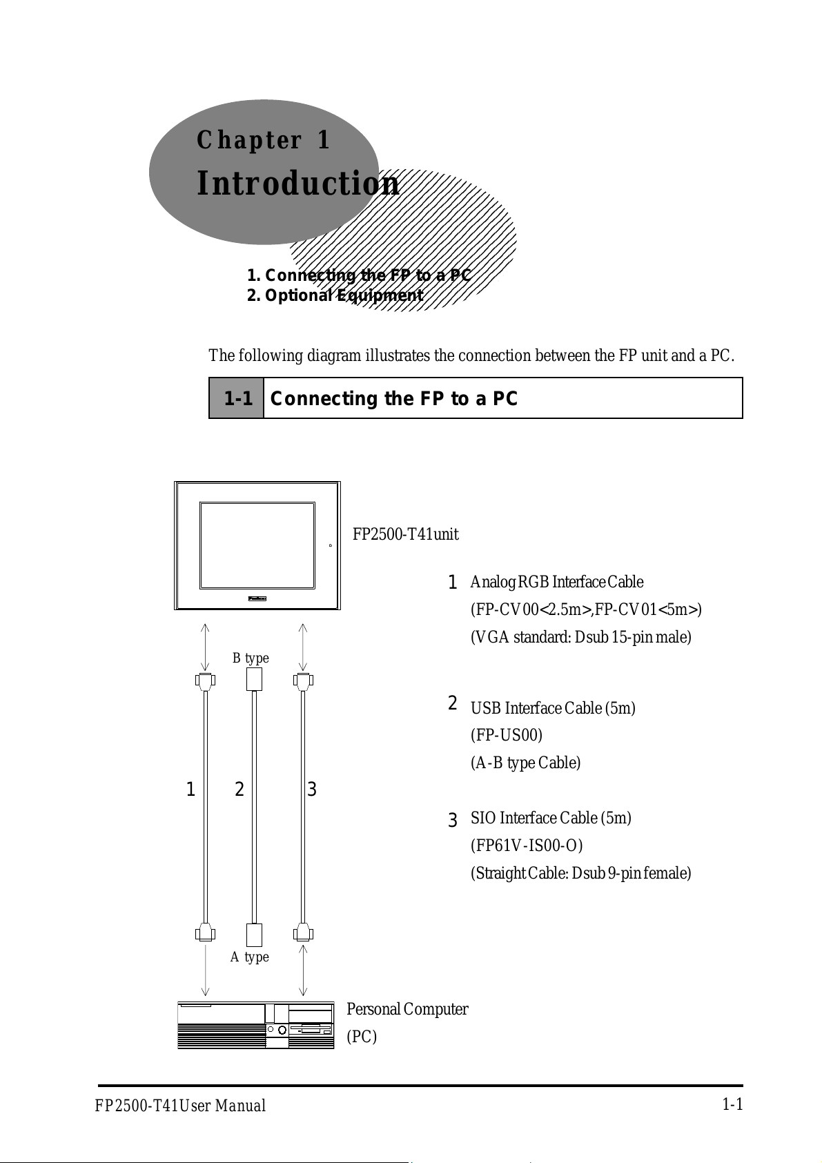
The following diagram illustrates the connection between the FP unit and a PC.
1-1 Connecting the FP to a PC
FP2500-T41unit
Analog RGB Interface Cable
1
(FP-CV00<2.5m>,FP-CV01<5m>)
(VGA standard: Dsub 15-pin male)
B type
2
USB Interface Cable (5m)
(FP-US00)
(A-B type Cable)
1
23
A type
SIO Interface Cable (5m)
3
(FP61V-IS00-O)
(Straight Cable: Dsub 9-pin female)
FP2500-T41User Manual
Personal Computer
(PC)
1-1
1-2 Optional Equipment
All optional items listed below are products of Digital Electronics Corporation.
Introduction
Interface
Maintenance
Parts
Optional
Parts
Item
SIO Cable FP61V -IS 00-O
RGB Cable
USB Cabl e FP-US00
Backlight
Bulbs
Installation
Brackets
Rubber
Gasket
Cover
Sheet
(Hard ty pe)
Mouse
Emul ator V2
Model Description
FP-CV0 0
FP-CV0 1
GP577RT-BL00-MS Replacement Backli ght bulbs .
GP070-AT01 Metal installat ion brackets for FP2500-T41
GP-WP10-MS
PSL- DF00
PL-TD000 Mouse Emulator software for FP
Serial interface cable (5m) used for t ouch
panel dat a transmission between the host
and the FP or command t ransmis sion to
the FP. This i s a straight Dsub9 pin femal e
cable.
Analog RGB i nterface cabl e when i m age
si gnal is output to the FP from the host.
VGA specifications (Dsub15 pin mal e)
FP-CV00 (2.5m), FP -CV 01 (5m)
USB i nterface cabl e (5m ) used for touch
panel dat a transmission between the host
and the FP or command t ransmis sion to
the FP.
A-B type c abl e.
Replacem ent rubber gasket, us ed when
ins talli ng the FP. S am e as the FP's
original gasket.
Provides disposable screen protection from
dust and other elements. The touch panel
can be used with the Cover Sheet at tached
(5 sheets / set)
* Operation environment is Windows®95, WindowsNT®4.0, Windows®98, Windows®2000.
When you use PL-TD000, hardware settings can not be automatically detected.
As a result, select the FP unit's currently connected COM Port, and enter the
settings given in the FP manual for the Allocated I/O address and Interrupt.
1-2 FP2500-T41User Manual
Chapter 2
Specifications
1. General Specifications 4. Cable Diagrams
2. Functional Specifications 5. Names and Functions of FP Parts
3. Interface Specifications 6. Flat Panel (FP) Dimensions
2-1 General Specifications (For DC24V)
2-1-1 Electrical Specifications
Ra ted Vo ltage
Rated V olta ge Range
Pow er Consumption
In-Rush Current
Voltage Endurance
Insulation Resistance
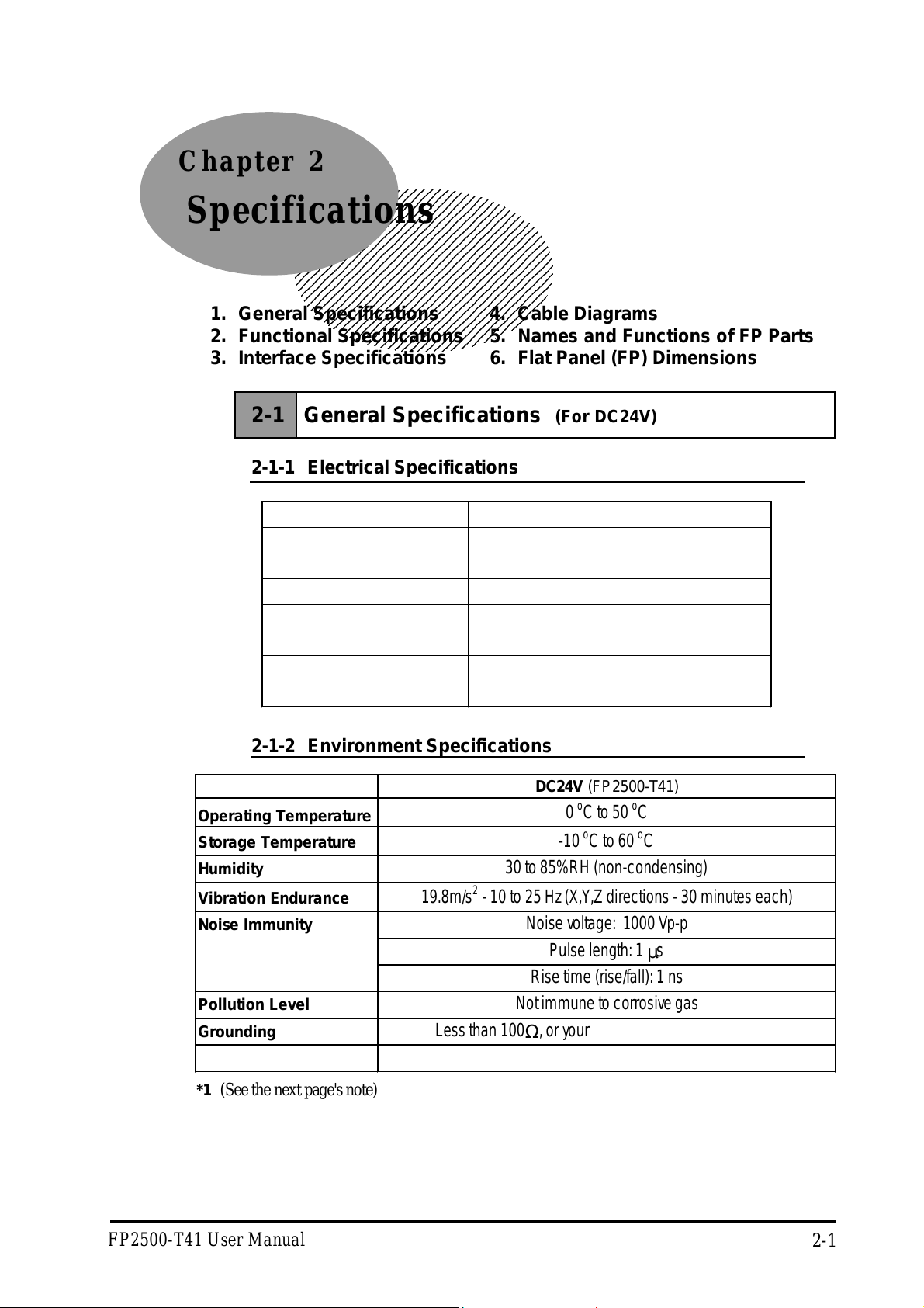
2-1-2 Environment Specifications
Operating Temperature
Storage Temperature
Humidity
Vibration Endura nce
Noise Immunity
DC24V
DC 19.2 V to DC 28. 8 V
50W or les s
30A or les s
A C1000V 20mA f or 1minute
(bet ween charging and FG te r minals)
10MΩ or higher at DC500V
(bet ween charging and FG te r minals)
DC24V
(FP2500-T41)
0 oC to 50 oC
-10 oC to 60 oC
30 to 85% RH (non-condensing)
19.8m/s2 - 10 to 25 Hz (X , Y, Z directions - 30 minutes each)
Noise voltage : 1000 Vp-p
Pulse length: 1 µs
Pollution Leve l
Grounding
Protection*1
*1 (See the next page's note)
FP2500-T41 User Manual
Rise time (rise/fall): 1 ns
Not immune to corrosive gas
Less t han 10 0Ω, or your country's applicable standard
Equivalent t o IP 65 f ( JE M1030)
2-1
Specifications
*1 (Continued from previous page)
The front face of the FP unit, installed in a solid panel, has been tested using
conditions equivalent to the standard shown in the specification . Even though
the FP unit’s level of resistance is equivalent to the standard, oils that should
have no effect on the FP can possibly harm the unit. This can occur in areas
where either vaporized oils are present, or where low viscosity cutting oils are
allowed to adhere to the unit for long periods of time. If the FP’s front face
protection sheet becomes peeled off, these conditions can lead to the ingress of
oil into the FP and separate protection measures are suggested. Also, if nonapproved oils are present, it may cause deformation or corrosion of the front
panel’s plastic cover. Therefore, prior to installing the FP be sure to confirm the
type of conditions that will be present in the FP’s operating environment.
If the installation gasket is used for a long period of time, or if the unit and its
gasket are removed from the panel, the original level of the protection cannot be
guaranteed. To maintain the original protection level, you need to replace the
installation gasket regularly.
2-1-3 Structural Specifications
DC24V (FP2500-T41)
External Dimensions 317W x 243H x 58D mm
We ight 3.5 k g or les s
Cooling Sys t em Natur al air circulation
2-2
FP2500-T41 User Manual

Specifications
2-2 Functional Specifications (For DC24 V )
Displa y M ed ia
Displa y S i z e
Display Area (mm)
Resolution
Display Colors
Brightness
Do t P i tc h (mm)
Touch Pane l
Display Mode
Interfaces
Backlight
TF T Acti ve matrix color LCD
26cm (type 10.4) Opposi te angle
221. 2W × 158.4H
640(H)×480(V)pixels(1pix el=R+G+B pixel)
262, 14 4 colors ( R/G/ B Six bit s each)
240cd/m2(typ)*1
0.33H×0.33W
Resolution: 1024×1024
Method : Resi st ive Film (Analog)
VGA graphi c & Text mode
640X480, 640X400 , 640X 350 mode display available.
720X400, 720X350 mode are al so avai l ab le, however,
th e 72 0X400, 720X350 s creens will display only a t 640 p i xels and the right side’s
horizontal 80 pi xels do not display.
VGA Graphic mode (DIPSW 4 is ON.)
640X480, 640X400 , 640X 350 mode display available.
In thi s case, the resolu tion 720 X400, 720X350 displays as hori zontal 640 pixels ,
but the i mages may be cut i f they do not match sampling.
However, all modes 400 lines an d 35 0 lines are center displayed.
With 350 pi xels, 400 pi xels, i ncluding 50 pixels at the top and bottom will be
enlarge d and displ ayed as 480 pixel s (1.2 times).
Analog RGB Interface
SIO Interface(touch Interface)
USB Interface(touch Interface)
Backlight can be changed.
o
Lifetime : 50,000 hour s when continuou sly l i t (*2) at 25
C.
*1 The brightness at central part of the screen when displaying all white.
*2 2.5 times decreased brightness may be the life span, but this value is only for
reference and not a guaranteed value.
FP2500-T41 User Manual
2-3
2-3 Interface Specifications (For DC 24V)
2-3-1 Analog RGB Interface
Input signal type Analog RGB
Input sig nal c haracteri stic Image s ignal : analo g RGB
Sy nchro nous si gnal : TTL le ve l, neg ativ e true or
positive true
Sc anning ty pe : no n-inte rlase
Specifications
Setting by OSD (On Screen
Display)
Siz e H Sync. V Sync. Dot Clock Range
Co ntrast A d jus tme nt
Sub Contrast Adjustment
Brightness Ad justment
Horizontal Display Position Adjustment
Vertical Display Position Adjustment
Horiz ontal A dj ustme nt
Phase Adjustment
Dimmer Adj ustment
Default Se tting (All Cle ar Functio n)
640 X 480 31.469±1 KHz 60±1 Hz 25. 175MHz± 1%
640 X 400 24.827±1 KHz 56±1 Hz 21. 053MHz± 1%
640 X 400 31.469±1 KHz 70±1 Hz 25. 175MHz± 1%
640 X 350 31.469±1 KHz 70±1 Hz 25. 175MHz± 1%
720 X 400 31.469±1 KHz 70±1 Hz 28. 322MHz± 1%
720 X 350 31.469±1 KHz 70±1 Hz 28. 322MHz± 1%
• Changeover from horizontal 720 pixels to 640 pixels is done via DIP switch.
• When the horizontal 720 pixel signal is input;
- VGA Graphic & T ext mode displays 640 pixels only and 80 pixels are not
displayed.
- VGA Graphic mode displays all pixels but images may be cut off if they do
not match the sampling .
• With vertical 350 pixels, 400 pixels including 50 pixels at the top and at the
bottom of the screen will be enlarged and displayed at 480 pixels (1.2 times).
2-4
• In VGA Graphic & text mode, the far right side's 80 pixels do not
display .
• Selection of display mode is done via switch SW1-4.
FP2500-T41 User Manual
Specifications
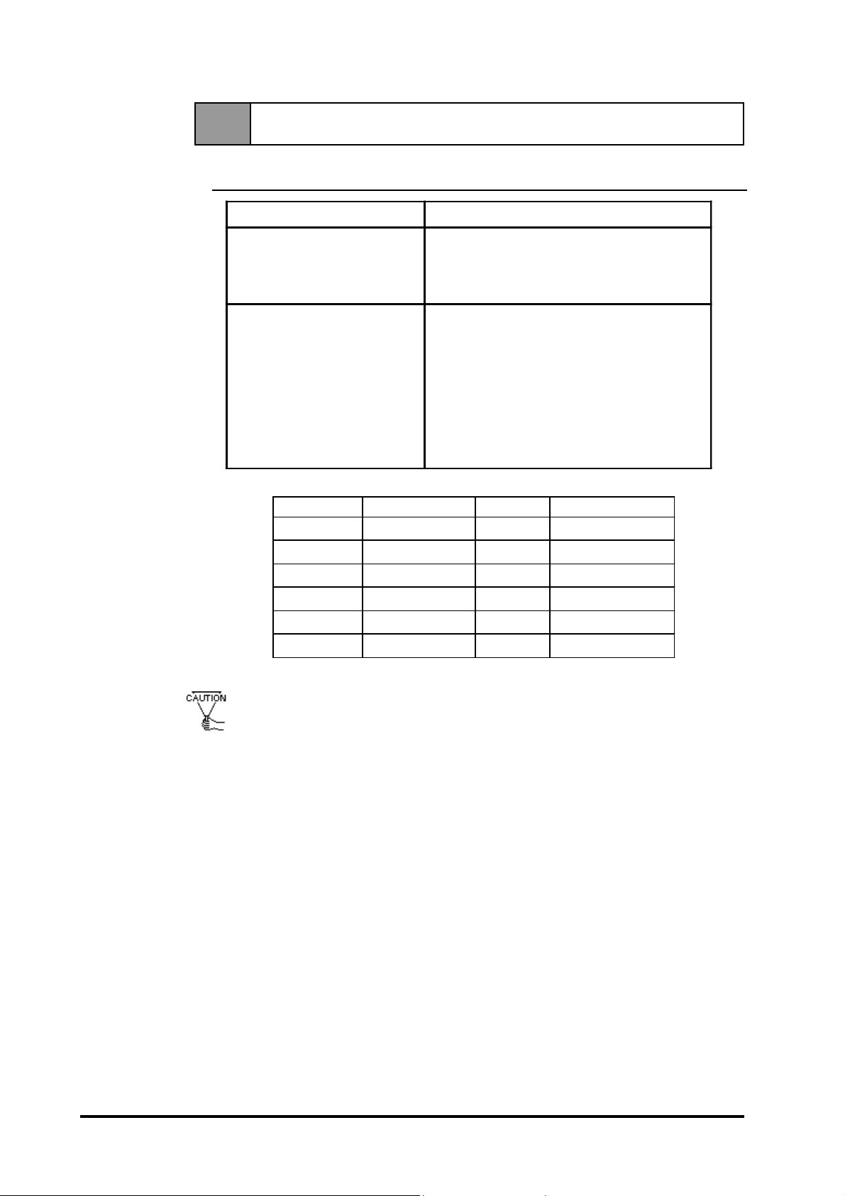
Pin Assignments and Signal Names for Analog RGB
Pin
No.
1 Analog R R sig nal inp ut
2 Anal og G G sig nal inp ut
3 Anal og B B si gnal inp ut
4 Reserved NC (spare for input)
5 Digital grounding Digital signal GND
6 Re turn R R si g nal GND
7 Re turn G G si g nal GND
8 Re turn B B si g nal GND
9 Reserved NC (spare for input)
10 Digi tal g ro und ing Digi tal si g nal GND
11 Re se rv e d NC (spare fo r input)
12 Res e rv ed NC (sp are fo r inp ut)
13 H. SY NC Horiz o ntal sy nc hrono us
14 V. SYNC Vertical synchronous
15 Res e rv ed NC (sp are fo r inp ut)
Sig nal Name Co nditi on Pin Lo cati on
sig nal inp ut
sig nal inp ut
15
11
5
1
Connector: Mini Dsub 15 pin type
Connector set screw: Inch type (4-40)
FP2500-T41 User Manual
2-5
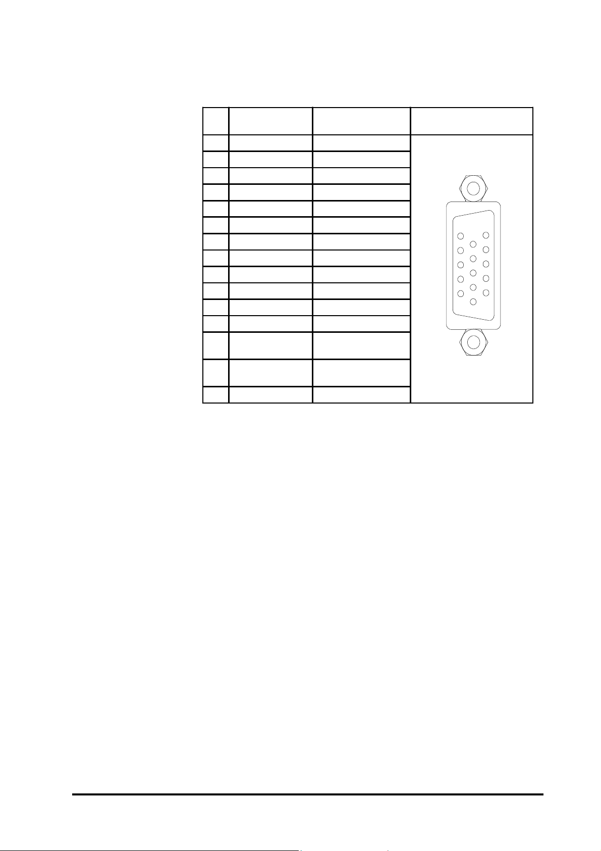
2-3-2 Serial Interface
Baud rate: 9600 b p s
Se r ia l Inte r fac e
Data l e ng th : 8 b i ts
Parity: none
Stop bit: 1
Pin Assignments and Signal Names for Serial Interface
Pin
Signal
No.
Name
1 CD Carrier Detect (FP->Host)
2 RD Receive Data (FP->Host)
3 SD S e nd Data (FP <-H os t)
4 DTR Data Term inal Re ady (FP <-Ho st)
5 GND Ground
6 DSR Data Set Ready (FP->Host)
7 RS Re q ue s t to S e nd (FP <-Ho s t)
8 CS Cl e ar to S e nd (FP ->Ho st)
9 NC No connection
Condition Pin Location
6
9
Specifications
1
5
Connector: Dsub 9 pin female
Connector set screw: Inch type (4-40)
Concerning Signal Names
Signal names used for the serial interface on FP units are designed to match
the pin order used on most PC serial interfaces, so that a straight cable can
be used to connect the two. Therefore, connect each pin's signal to the same
signal name on the PC side.
For example, pin #2 'RD' should be connected to the 'RD' input terminal on
the PC's connector .
Refer to section "2-4 Cable Diagrams" for each signal's direction.
2-6
FP2500-T41 User Manual

Specifications
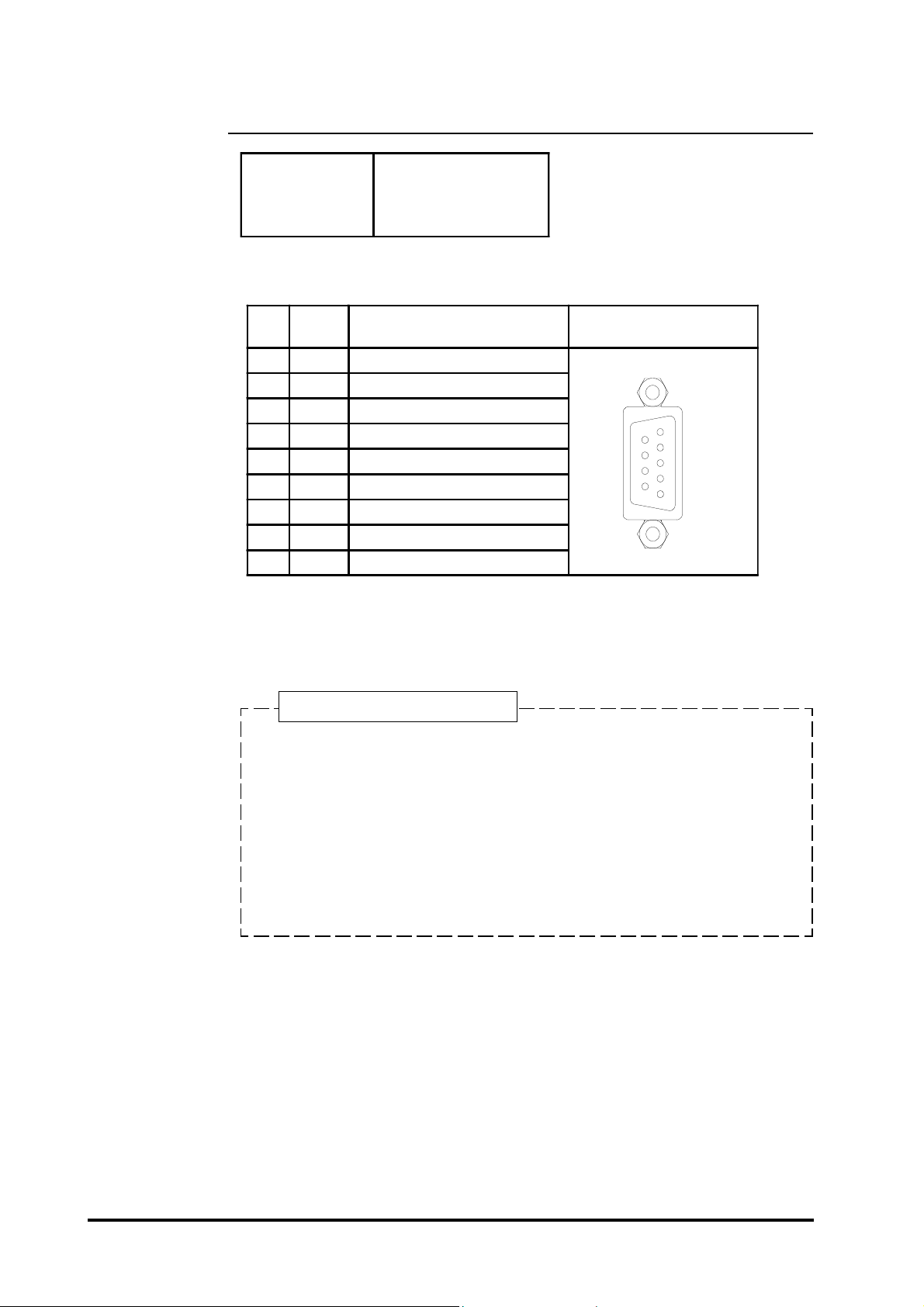
2-3-3 USB Interface
Pin Assignments and Signal Names for USB Interface
Pin
NO.
Signal
Name
1 USB1 -5V +5VIN
2 USBD1(-) USBdata(-)
3 USBD1(+) USBdata(+)
4 GND Ground
Condition Pin Location
Communication Low speed Device
Connector: B type connector
12
43
FP2500-T41 User Manual
2-7
 Loading...