

Digital Equipment Prioris XL 6000 Series Service Maintenance Manual

PRIORIS XL 6000
Prioris XL 6000 Series Server
Service Maintenance Manual
Part Number: ER-B60 WW-SM. A01
Digital Equipment Corporation

March 1997
The information in this document is subject to change without notice and should
not be constr ued as a c om m itment by Digit al E quipm ent Corporation.
Digital Equipment Cor por ation assumes no res pons ibility for any er r or s that
might appear in this doc um ent.
The soft war e, if any, des c r ibed in this document is furnished under a license and
may be used or copied only in accordance with the terms of such license. No
responsibility is as s um ed for the use or r eliability of sof tware or equipment that is
not supplied by Digital E quipm ent Corporation or its affiliated companies.
Restrict ed Rights: Use, duplic ation, or disclos ur e by the U.S. Government is
subject to restrictions as set forth in subparagraph (c) (1) (ii) of the Right s in
Technical Data and Com puter Soft war e c laus e at DFARS 252. 227- 7013.
Prioris XL 6000 Ser ies S er v er S er v ic e M aintenance Manual
CopyrightÓ Digital Equipment Cor por ation.
All Rights Reserv ed.
AMI is a regis tered trademar k of American Megatrends
DEC, Prioris, ServerWO RKS, and the Digital logo are trademarks of Digital
Equipment Corporation.
Intel and Pentium Pro are registered trademarks of Int el Corporat ion.
Microsoft, Windows NT, and Windows 95 are registered tr ademarks of Microsoft
Corporation.
Novell and NetWare are U.S. registered trademarks of Novell I nc.
OS/2 and PS/2 are registered trademarks of Internat ional Business Machines
Corporation.
SCO UNIX is a trademark of The Santa Cruz Operation, Inc.
SCSI
Select
is a registered trademark of A daptec Corporation.
All other trademarks and registered t r ademarks are the property of t heir
respective holder s .

PRIORIS XL 6000
FCC ID: B6XWW
The FCC wants you to know...
This equipment has been tested and found to comply with the limits f or a Clas s
B digital device, pur s uant to Part 15 of the FCC rules . These limit s ar e des igned
to provide reasonable pr otection against har m ful interfer enc e in a r es idential
installation.
Any changes or modifications made to this equipment m ay v oid the user's
authority to operate this equipm ent.
This equipment gener ates, uses, and can radiate radio frequency energy and, if
not installed and used in ac c or danc e with the instr uc tions, may c aus e har m ful
interferenc e to radio communications. However, there is no guarantee that
interferenc e will not occur in a part ic ular ins tallation. I f this equipment does
cause harmful interference to radio or televis ion r ec eption, which can be
determined by t ur ning the equipment off and on, the user is enc our aged to try t o
correct the interfer enc e by one or m or e of the following meas ur es :
• Reorient or relocate the receiving antenna
• Increase t he s epar ation between the equipment and receiver
• Connect the equipment into an outlet on a c ir c uit different from t hat to
which the receiver is c onnec ted
• Consult the dealer or an ex per ienc ed r adio/TV tec hnic ian for help
All external cables c onnec ting to this bas ic unit need to be shielded. For cables
connecting to option cards, s ee the option manual or installation instr uc tions.
This digital apparatus does not exc eed the Class B limit s for radio noise
emissions set out in the radio inter ference regulations of the Canadian
Department of Communications .

This equipment is in the 2nd Class categor y ( information equipment to be used
in a residential area or an adjacent area theret o) and conf orms to the standards
set by the V oluntary Control Counc il For Inter ference by Data P r oc es s ing
Equipment and Electronic Office Machines aimed at preventing radio
interferenc e in s uc h r es idential area.
When used near a radio or TV receiver, it may becom e the cause of radio
interferenc e.
Read the instruc tions for cor r ec t handling.
This equipment m eets or exceeds r equir em ents for safety in the U.S. (UL 1950),
Canada (CSA C22.2 No. 950) , and Europe (EN 60950/ IEC 950) with Nordic
requirements.
This equipment m eets or exceeds the ergonomic requirem ents of ZH1/618 and
is certif ied to bear the GS m ar k by TUV Rheinland of Ger m any .
This equipment has been tested for r adio frequency emiss ions and has been
verified to m eet VDE 0871 Class B.
This equipment has been tested for r adio frequency emiss ions and has been
verified to m eet AZ/NZS AS3548 requirem ents for I TE equipment f or A us tralia
and New Zealand.

i
PRIORIS XL 6000
Contents
1
Introduction
Reliability/Availability....................................................................................................... 1-1
Server Expansion........................................................................................................... 1-2
Server Management and Security.................................................................................. 1-3
Server Software and Documentation ............................................................................. 1-3
Diagnostic Software........................................................................................................ 1-4
Server Utilities and Technical Support............................................................................ 1-5
Important Ergonomic Information................................................................................... 1-6
2
Server S oftware and Utilities
Introduction..................................................................................................................... 2-1
ServerWORKS Quick Launch........................................................................................ 2-2
System Configuration Utility (SCU)................................................................................. 2-2
Startin g th e SCU......................................................................................................... 2-3
Usin g th e SCU............................................................................................................ 2-4
Flash Memory Update Program..................................................................................... 2-5
http://www.digital.com/info/service.html.......................................................................... 2-5
SCSISelect Utility............................................................................................................ 2-5
Diagnostics..................................................................................................................... 2-6
3
Server Com ponents
Introduction..................................................................................................................... 3-1
Disconnecting External Devices and Power................................................................... 3-1
Removing and Installing the Side Panel......................................................................... 3-2
Serve r F ro n t V iew........................................................................................................... 3-4
Serve r L e ft S ide View..................................................................................................... 3-6
Serve r R e a r View........................................................................................................... 3-8

Contents
ii
Main Logic Board Components and Connectors............................................................ 3-10
Tools Needed................................................................................................................. 3-12
Static E lectric ity .............................................................................................................. 3-12
4
Server Managem ent
Introduction..................................................................................................................... 4-1
Obtaining Information Using Server Management Software.......................................... 4-2
Disp layin g Server S ta tu s U s ing the H a rd ware................................................................ 4-3
Serve r S ta tu s.............................................................................................................. 4-4
POST Beep Codes......................................................................................................... 4-5
POST Codes and Countdown Codes............................................................................. 4-6
Normal Port-80 Codes and Countdown Codes .......................................................... 4-6
Recovery Port-80 Codes and Countdown Codes....................................................... 4-10
5
Installing Additional Memory
Introduction..................................................................................................................... 5-1
Installing Additonal Server Memory................................................................................ 5-1
Server DIMMs Requirements......................................................................................... 5-1
Memory C o n fi g u ra tion Guidelines.................................................................................. 5-2
Upgra d ing Memo ry......................................................................................................... 5-3
Instal l ing D IMMs............................................................................................................. 5-4
Memory Troubleshooting................................................................................................ 5-6
Installing Additional Video Memory................................................................................. 5-7
6
Installing Disk and Tape Dr ives
Introduction..................................................................................................................... 6-1
Disk and Tape Drive Configuration Guidelines............................................................... 6-1
CD-R OM Drive Confi g u ra ti o n Gu idel i n e s....................................................................... 6-1
SCS I C o n figuration Gui d e line s....................................................................................... 6-2
SCSI ID and Termination............................................................................................ 6-2
Setting IDs and Termination....................................................................................... 6-2
Boot D e v ice................................................................................................................ 6-3
External Channel ........................................................................................................ 6-3
Drive ID....................................................................................................................... 6-3
Cables......................................................................................................................... 6-4

Contents
iii
PRIORIS XL 6000
Installing Optional Drives................................................................................................ 6-4
Instal l ing a 5 ¼-In c h D e v ice in to th e F r o n t A c ce s s D rive Ba y...................................... 6-5
Expansion Brackets ................................................................................................ 6-7
Instal l ing a 3 ½-In c h D e v ice in to th e In te rn a l Driv e B a y............................................... 6-8
Connecting an External SCSI Storage Box.................................................................... 6-10
7
Installing Expansion B oards
Introduction..................................................................................................................... 7-1
ISA Expansion Board Configuration Guidelines ............................................................. 7-1
PCI Expansion Board Configuration Guidelines............................................................. 7-3
Configuring Your PCI Expansion Boards Using the SCU............................................... 7-3
Boot D e v ices.................................................................................................................. 7-3
Server Boot Sequence................................................................................................ 7-4
Server Scan Sequence............................................................................................... 7-5
Boot D e v ice As signmen t Exampl e.............................................................................. 7- 6
PCI S ca n Ord e r E x a mp l e....................................................................................... 7-6
Identifying PCI Devices in the SCU............................................................................. 7-8
Installing Expansion Boards ........................................................................................... 7-10
Adding ISA Expansion Boards.................................................................................... 7-10
Installing ISA Expansion Boards................................................................................. 7-11
Installing PCI Expansion Boards................................................................................. 7-13
Adding PCI Expansion Boards.................................................................................... 7-15
Relocating Expansion Boards..................................................................................... 7-16
8
Connecting SCS I A dapters
Introduction..................................................................................................................... 8-1
SCS I C o n figuration Gui d e line s....................................................................................... 8-1
SCS I C o n tro ller C a b le Con figuration.............................................................................. 8-1
Single Channel SCSI Configuration............................................................................ 8-2
9
Server S ecur ity Featur es
Introduction..................................................................................................................... 9-1
Security Door and Side Panel Chassis Lock.................................................................. 9-2
Padl o c k R ing.................................................................................................................. 9-3
Administrative and User Password................................................................................. 9-3
If You F o rg e t Y o u r Passw o rd......................................................................................... 9-4
Additional Security Features........................................................................................... 9-6

Contents
iv
10
Troubleshooting
Introduction..................................................................................................................... 10-1
Initial Troubleshooting..................................................................................................... 10-2
Running the Diagnostics................................................................................................. 10-3
Diagnostics Utility Keys............................................................................................... 10-4
Server Troubleshooting .................................................................................................. 10-5
Disk Drive Troubleshooting............................................................................................. 10-8
Tape Drive Troubleshooting ........................................................................................... 10-11
Monitor Troubleshooting................................................................................................. 10-12
CD-ROM Troubleshooting.............................................................................................. 10-13
Diskette Drive Troubleshooting....................................................................................... 10-14
11
Field Service Replacem ent
Introduction..................................................................................................................... 11-1
Recommended Tools..................................................................................................... 11-1
Other Materials Needed.............................................................................................. 11-2
Special Tools Required............................................................................................... 11-2
Remedial Diagnostic Test Software............................................................................ 11-2
Virus S o ftware Info rma tion......................................................................................... 11-2
BIOS Ve rs ion Info rma ti o n........................................................................................... 11-2
Resto ri n g th e Serial Numb e r.......................................................................................... 11-3
Removing and Replacing Components.......................................................................... 11-3
Removing and Replacing the Power Supply and Control Assembly.............................. 11-4
Removing and Replacing the Diskette Drive.................................................................. 11-6
Removing and Replacing the CD-ROM Drive................................................................ 11-8
Removing and Replacing the Drive Bay Cooling Fan..................................................... 11-10
Removing and Replacing the Lower Cooling Fan ......................................................... 11-12
Removing and Replacing the Speaker........................................................................... 11-14
Replacin g th e L ithium Battery......................................................................................... 11-15
Removing and Replacing the Main Logic Board............................................................. 11-18
12
Field Service IPB
Introduction..................................................................................................................... 12-1
Serve r F ro n t V iew........................................................................................................... 12-2
Serve r L e ft-S ide View..................................................................................................... 12-4
Miscellaneous................................................................................................................. 12-6
Labels and Nameplates.................................................................................................. 12-6

Contents
v
PRIORIS XL 6000
13
Field Service Notes
Introduction..................................................................................................................... 13-1
14
Power U p and Boot S equence
Powe r On Self T e st........................................................................................................ 14-1
Server Boot Sequence ................................................................................................... 14-2
Boota b l e CD-ROM...................................................................................................... 14-2
Drive A or Dri v e C....................................................................................................... 14-2
Drive C Assi g n m e n t.................................................................................................... 14-2
15
Product Refer ence and S uppor t
Introduction..................................................................................................................... 15-1
A
Technical Specification
Introduction..................................................................................................................... A-1
Serve r S p e c i ficatio n s...................................................................................................... A-1
Performa n c e S p e c i ficatio n s........................................................................................ A-2
Serve r D imensi o n s..................................................................................................... A-2
Envi ro n me n ta l Spec ifications...................................................................................... A-3
ISA Expansion Slots....................................................................................................... A-3
PCI Local Bus Expansion Slots...................................................................................... A-3
Power Supply Input Power Requirements...................................................................... A-4
Power Supply Output Specifications............................................................................... A-4
Power Cord Requirements............................................................................................. A-4
Envi ro n me n ta l Featu re s................................................................................................. A-5
Main Logic Board Jumper Settings................................................................................. A-6
Server CPU Voltage and Temperature Ranges............................................................. A-8
CPU Voltage Range ................................................................................................... A-8
VRM Voltage Range................................................................................................... A-8

Contents
vi
B
Device Mapping
Introduction..................................................................................................................... B-1
CPU Me mo ry A d d re s s Ma p........................................................................................ B-2
I/O Addre s s Ma p ......................................................................................................... B-2
Serve r In te rru p t L e ve ls ............................................................................................... B-3
PCI C o n fi g u r a ti o n S p a c e A d d r e ss Ma p...................................................................... B-3
C
SCU Features
Introduction..................................................................................................................... C-1
Systems Gro u p........................................................................................................... C -3
Memory Subsystem Group......................................................................................... C-3
Onboard Disk Controllers............................................................................................ C-3
Onboard Communication Devices.............................................................................. C-4
Floppy Drive Subsystems Group................................................................................ C-5
BIOS Language Support Group ................................................................................. C-5
Keyboard (KB) and Mouse Subsystem Group........................................................... C-6
Cons o l e Redi re ction.................................................................................................... C-6
Security Subsystems Group....................................................................................... C-7
Boot Subsystem Group .............................................................................................. C-8
SCS I R OM BIOS Opti o n s Gro u p ................................................................................ C-8
Management Subsystem Group................................................................................. C-9
System Management Options.................................................................................... C-10
D
Caring For Y our S er ver
Introduction..................................................................................................................... D-1
Cleaning the Server........................................................................................................ D-1
Cleaning the Screen....................................................................................................... D-1
Cleaning the Mouse........................................................................................................ D-2
Movin g th e S e rv e r.......................................................................................................... D-2
Packing the S e rv e r..................................................................................................... D-3
Instal l ing the S e rv e r a t a New L o ca tion....................................................................... D-3

vii
PRIORIS XL 6000
P
Preface
P
This
Service Maint enanc e M anual
is a troubleshoot ing guide that can be used
for refer enc e when s er v ic ing P r ior is X L 6000 S er ies s er v er s .
Digital reserves the right to m ak e c hanges to this
Service Maint enanc e M anual
without notice. Accordingly, the illustrations and procedures in t his document
might not apply to all Prioris XL 6000 S er ies s er v er s to be serviced sinc e m any
of the diagnost ic tests are des igned to test m or e than one product.
CAUTION:
Digital recommends that only A+ certified
engineers attempt to repair this equipment. All
troubleshooting and repair procedur es ar e det ailed to suppor t
subassembly/module level exchange. Because of the
complexity of the individual boards and subassemblies, no
one should atttempt to make repairs at the component level or
make modifications to any printed circuit boar d. I m pr oper
repairs can create a safet y hazar d. Any indications of
component replacement or cir cuit boar d modifications might
void any warranty or exchange allowances.

Preface
viii
Organization
This guide contains the following:
•
Chapter 1:
Introduction
This chapter pr ov ides information about y our
server such as : features , server software and documentation,
diagnostic sof tware, serv er utilities and tec hnic al s uppor t, and ergonomic
information.
•
Chapter 2:
Server Sof tware and Utilities
This chapter describes the
server sof tware and utilities that are supplied wit h y our s er v er .
•
Chapter 3:
Server Component s
This chapter pr ov ides information about
the server’s c om ponents and associat ed pr oc edur es s uc h as r em ov ing the
side panel.
•
Chapter 4:
Server Management
This chapter describes how to
manage your server us ing a network manager, s pec ifically Digital’s
ServerWORKS Manager. Options for P r ior is X Le c onfigurations.
•
Chapter 5
Installing Additional Memory
This chapter describes how
to install addit ional m em or y on the main logic board.
•
Chapter 6
Installing Disk and Tape Drives
This chapter describes
how to install opt ional dis k dr iv es , tape drives, and an external storage
box.
•
Chapter 7
Installing Ex pans ion B oar ds
This chapter describes how
to install I S A and P CI expansion boards.
•
Chapter 8
Connecting SCSI A dapters
This chapter describes how to
connect mass s torage devices t o the onboard SCSI c ontroller.
•
Chapter 9
Server Security Features
This chapter describes the
various security featur es that are available t o pr ev ent server or data
theft.

Preface
ix
PRIORIS XL 6000
•
Chapter 10
Troubleshooting
This chapter describes initial and advanced
troubleshooting s olutions.
•
Chapter 11:
Field Service Replac em ent
This chapter describes field
service replacem ent procedures. For example, the main logic board, power
supplies, fans , etc.
•
Chapter 12:
Field Service Illustrat ed P ar ts Breakdown
This chapter lis ts
orderable part number s for Field Replaceable Unit s ( FRUs).
•
Chapter 13:
Field Service Notes
This chapter enables field service
personnel to recor d per tinent servic e information.
•
Chapter 14:
Power Up and Boot Sequenc e
This chapter des r ibes the
server’s power up and boot sequence.
•
Chapter 15:
Product Ref er enc e and S uppor t
This chapter lis ts product
reference and suppor t informat ion.
•
Appendix A:
Technical Specifications
— This appendix lists server
operating specif ic ations. Also inc luded is jum per information on t he
main logic board. It also provides a list and descript ion of error
messages that might display and er r or c odes that might s ound if a
failure occurs .
•
Appendix B:
Device Mapping
— This appendix prov ides a s er ies of
tables listing m apping and addr es s information related to server m em or y
and various main logic board dev ic es ( k ey boar d c ontroller, int er r upt
controller, Direct Memory Access (DMA) controller, etc.).
•
Appendix C:
SCU Features
— This appendix lists the available SCU
resource and conf igur ation options.
•
Appendix D:
Caring for your S er v er
— This appendix prov ides s ugges tions
for cleaning and moving y our s er v er .

Preface
x
Conventions
Convention
Example
Description
Installation Guide
Italics are typically used for titles, com m ent s, and r ef er ences
to other sections of t his document or other documents.
c:\windows>
SCU.BAT
Monospaced text indicates informat ion that your server or
software displays. For example, a direct or y pat h or er r or
message.
Monospaced text can also indicate a command that you need
to ent e r to r un a n ap p lic ation or u tility.
[Enter] Square brackets surrounding text r epr esent s a keyboar d key.
[Ctrl]+[Alt]+[ Del] A plus sign indicates that the keys shown should be pressed
at the same time.

Preface
xi
PRIORIS XL 6000
Abbreviations
Abbreviation Meaning
BIOS Basic input/output system
CPU Central processing unit
DIMM Dual in-line memory module
DMA Direct memory access
DRAM Dynamic random access memory
ECC Error correction code
ECP Extended capabilities por t
EPP Enhanced parallel port
FRU Field replaceable unit
h An h suffix to a numerical value denotes hexadecimal
numbers. For exam ple, 0F8h equals 0F8 hexadecimal.
IDE Integrated dr ive electr onics
I/O Input/output
ISA I ndust r y st andar d ar chit ect ur e
MS-DOSä Microsoft Disk Operating System
PCI Peripheral component interconnect
POST Power-on self test
RAM Random access memor y
ROM Read only memor y
RTC Real-t ime clock
SCSI Sm all computer syst em int erface
SCU Syst e m conf ig uration utility
VGA Video graphics array
Windows NT Microsof t Windows NT operating system sof t ware
ZIF Zero insertion force
Preface
xii
Special Notices
Three special not ic es ar e us ed to emphasize specific information.
WARNING:
Indicates the presence of a hazar d t hat can
cause personal injury if the hazard is not avoided.
CAUTION:
Indicates the presence of a hazard that might
cause damage to hardware or t hat might corrupt sof t war e.
NOTES:
Used to provide additional information.
Preface
xiii
PRIORIS XL 6000
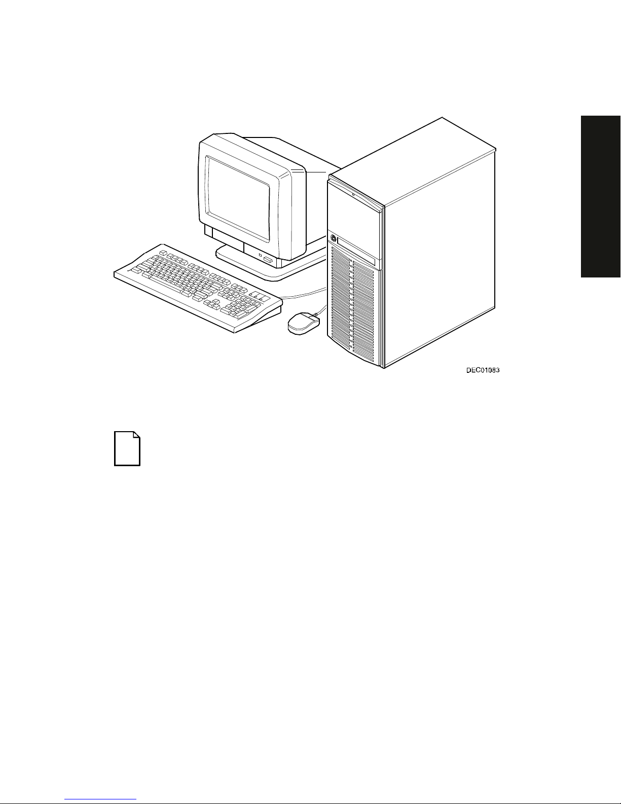
Typical Prioris XL 6000 Series Server
NOTE:
Your monitor, keyboar d, and m ouse m ight look diff er ent .

1-1
PRIORIS XL 6000
1
Introduction
1
The Prioris XL 6000 Series server is a high-performance, highly-scaleable
network and applicat ion s er v er featuring the latest in modular CP U and s torage
technology. The Prioris XL 6000 S er ies s er v er pr ov ides the following feat ur es :
Reliability/Availability
CPU
Single (1P) Pent ium P r o pr oc es s or m ode. The
CPU operates using a 64- bit memory int er face and
an internal L2 cache.
Error Correction Code
(ECC) Protested Memory
Recovery fr om s ingle- bit cache and memory er r or s .
Power Supply
Shipped with a 300 watt power s upply for normal
operation.
Variable Fan Speed
Automatic ally adjus ts fan speed acc or ding to
ambient temper ature.
Internal Sens or s
Monitors int er nal s er v er temperatures , fan
operation, and power s upply temperatures and
voltages.

Introduction
1-2
Server Exp ans ion
Flexible Memory
Architecture
ECC memory suppor t. Server m em or y c an be
upgraded from 16 MB to 512 MB on the main logic
board.
Two ISA E x pans ion
Slots and Thr ee P CI
Expansion Slots
Accommodates industry-standard expansion boards
such as network, Small Computer System I nt erf ace
(SCSI), and modems.
Integrat ed S V GA Video
Controller
Supports managem ent and configurat ion applic ations
locally (on the main logic boar d) without use of an
expansion slot.
Single Channel SCSI
Controller
Supports narr ow and fast wide ext er nal and internal
SCSI devices .
Capacity for E ight
Internal Storage
Devices
Accommodates one CD-ROM drive (option on some
Prioris XLe 6000 Ser ies c onfigurations), a 3 1/2 inch
floppy, and f our 3½- inc h, 1.5-inch high or s ix 3½- inc h,
1-inch high hard disk driv es .
External I/O Ports
Two serial port s and one par allel por t to support
external options s uc h as a pr inter, modem, or local
terminal.
External net wor k por t
One 10/100Base- T (10/100 Mb/ s ) por t to support an
external networ k c onnec tion.
Integrat ed Network
Controller
Provided by an Intel PCI LAN controller on the main
logic board.

Introduction
1-3
PRIORIS XL 6000
Server Management and Security
Server Diagnost ic s
Allows local and remot e diagnos is of server problem s .
Hardware Configurat ion
Allows local and remot e s er v er c onfiguration.
RAM-Based Error Log
Records star tup error mess ages .
Firmware Upgrade
Utility
Upgrades firmwar e v er s ions .
Key Lock
Limits acces s to server com ponents.
Server Software and Documentation
The following sof tware and documentation are supplied with your s er v er :
•
ServerWORKS Manageability S uite contains Serv er WORKS Q uic k
Launch, Server WORKS Manager ( The CD-ROM driv e is an option on
some Prioris X Le 6000 S er ies c onfigurations. ) , and licenses.
−
ServerWORKS Quick Launc h c ons is ts of a bootable CD- ROM
disk and referenc e guide. The Quick Launc h pr ogr am s teps you
through the initial server setup and operating system installation
process. ( The CD-ROM driv e is an option on some Prioris X Le
6000 Series configur ations.)
Refer to t he S er v er WORKS Q uic k Launc h Reference Guide and t he
ReadMe.txt file, which is loc ated on the Quick Launc h CD- ROM.
−
ServerWORKS Manager cons is ts of two CD- ROMs, sev er al
floppy disket tes, User Guide, and support ing doc um entation
(optional on the Pr ior is X Le 6000 S er ies ) .

Introduction
1-4
•
Server documentation box contains this System Reference, an
Installat ion Guide, a Document ation Overview, Warrant y information,
Options manuals , and Registrat ion Car d.
NOTE: You might have or der ed additional options such as har d
disk drives, tape back-up systems, CD-ROM s, or m odem s that
have been installed in your server. The document at ion and any
related diskettes for t hese opt ions have also been provided. Save
this material for future reference.
Diagnostic Software
Diagnostic sof tware is shipped with y our s er v er on the Quick Launch CD- ROM.
This software contains an adv anc ed s et of diagnostic utilities that can be used to
identify and cor r ec t problems you might encounter when installing, configur ing,
or using your serv er . There are t wo way s to access t he s upplied diagnos tic
software:
1. During your server ins tallation process , the diagnostic s oftware will be
automatically copied to a subdirectory on the MS-DOS partit ion (only if
you selected the option t o creat e an MS-DOS partition). T his allows you
to run the diagnostic software anytime from t he MS-DO S partition you
created.
NOTE:
The CD-ROM drive is an option on some Prioris XLe 6000
Series configurations. If your ser ver is not equipped with a CDROM drive, you will need to use another per sonal c om puter that
has a CD-ROM drive in order to create diagnost ic diskett es.
Refer to the
Quick Launch. Users Guide
for more information on
how to create server utilit y and dev ice dr iv er dis kettes.

Introduction
1-5
PRIORIS XL 6000
2. Using the Installations & Ut ilities button and then selecting t he Utilities
page from the S er v er WORKS Q uic k Launc h CD- ROM, you can c r eate
a bootable diagnostic s oftware diskette. T his allows y ou to run the
diagnostic sof tware anytime us ing the diskett e y ou c r eated.
For additional information, r ead any README files that ar e on the diagnostic
diskette you created.
NOTE: Digital strongly recommends that you copy t he diagnostics
to a diskette and use this diskette t o r un t he diagnostics on your
server.
Server Ut ilities and Technic al Support
Current serv er utilities and tec hnic al s uppor t informat ion is av ailable on the
Quick Launch CD-ROM disk and the Digital Bulletin Board Service (BBS). For
access to the Digital BBS in the USA, dial (508) 495-8800 or on the world wide
web at:
http: // www. d ig it a l. co m
or
http: // www. d ig it a l. co m/in f o / se rvice . h t ml
If you need additional information, access “ Service I nf or m at ion” located in the
ServerWORKS Quick Launch program t hat is on your CD-ROM disk.

Introduction
1-6
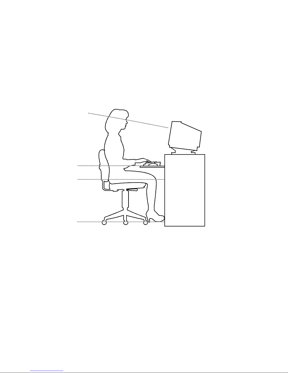
Important Ergonomic Information
After the server is ins talled, it is im por tant to apply the following ergonomic
information.
•
Be comfortable in your work spac e.
•
Change your posture frequently.
•
Proceed according to the recomm endations in the following table and
figure.
Adjus t So . . .
Chair Feet are flat on the f loor .
Legs are vertical form ing a right angle to t he floor.
Your weight is off your thighs and they ar e horizontal. Keep the
back of your knees away from t he seat so you do not com pr ess
the area behind them, which could rest r ict the blood flow.
Upper body is erect and lower back is supported with a backrest.
Keyboard or mouse Your wrists are straight and do not bend m or e t han 15 degr ees.
They may be supported when resting but not on shar p edges.
Type comfortably, with no mor e key pr essur e t han needed t o
feel the contact point.
Upper arms are str aight down at your sides, elbows are close to
your sides and support your arm weight. For ear m s ar e at a 70
degree to 90 degree angle.
If you use a mouse, r est your hand on t he m ouse so your wrist
is not on the work surface. Operate the mouse close t o your
body’s centerline.
Head Avoid neck strain. Your head should incline downward, but no
more than 15 to 20 degr ees.
Monitor No higher than the level of your eyes and at the cor r ect distance
for your vision.
Avoid eye fatigue, which can be caused by glare, image quality,
uncomfortable fur nitur e, eye height, and uncorrected vision. If
you cannot focus to read at diff er ent dist ances, you m ay need
special glasses. Relax your eyes periodically by looking at
distant objects.

Introduction
1-7
PRIORIS XL 6000
Work breaks Take periodic work breaks. Morning, lunch, and aft er noon
breaks during the 7-hour workday m eet m ost r ecom m endat ions.
Take advantage of work breaks t o m ove ar ound and do ot her
activities.
Lighting Avoid direct lighting or sunlight on the screen, which causes
glare and reflections. Place lighting behind or to the side of your
work area, and distribute t he lighting evenly on your work ar ea.
Your server’s monitor scr een has an antiglare treatment to
reduce glare. Adjust the brightness and cont r ast cont r ols as
needed.
Noise Keep background noise at a minimum. Background noise above
65 dBA is tiring. Sound-absorbing materials (cur t ains, car pet ing,
and acoustic tile) can help reduce background noise.
Temperature 20 to 23 degrees C (68 to 74 degrees F) .
Humidity 30% to 70%.
Ventilation Provide adequate air ventilation to avoid fatigue and to operate
the equipment.
Space between set ups > 70 cm (28 in.) center t o center, pref er ably > 152 cm ( 60 in. ) .
Introduction
1-8
IMPORTANT: If you exper ience pain or discomf or t during
use of the server, t ake a r est br eak and r eview the instr uct ions
for proper er gonom ic set up and use. I f the pain or discomfort
continues after resum ing use of t he ser ver , discont inue use
and report the condition to your job supervisor or physician.
DEC00454
Figure 1-1. Providing a Comfortable Working Environment

2-1
PRIORIS XL 6000
2
Server Software and Utilities
2
Introduction
This chapter describes the ut ilit ies supplied with your server. Server utilities
include:
• ServerWORKS Quick Launc h This software is used to ins tall a
network operating system onto the server
1
. The CD-RO M als o c ontains
various drivers and on- line doc um entation.
• System Configuration Utility (SCU) This utilit y allows y ou to configure
your server when r eloc ating, adding, or r em ov ing ISA/PCI expansion
boards and when changing your server’s factory-defined sett ings.
• Flash Memory Update This ut ility enables you to update or restor e
your server’s B IOS and IS A /PCI conf igur ation informat ion.
• SCSI
Select
Utility This utility allows y ou to configure and view
settings of the installed A daptec SCSI c ontroller and SCSI dev ic es .
• Diagnostics T his utility is us ed to verify s er v er oper ation.
1
Full Quick Launch functionality is only available to systems that have a bootable CD-ROM drive
installed. However, the Quick Launch media can be accessed on any other personal computer that
has a CD-ROM drive. The information, documentation, device drivers, and individual server utilities
can be downloaded onto diskettes, enabling you to use the information on the CD-ROM disc without
an actual CD-ROM drive being installed in your Prioris XLe 6000 Series server.

Server Soft war e and Utilities
2-2
ServerWORKS Quick Launch
Quick Launch is used to install the server’s Net work Operating System (NOS).
In addition to pr ov iding quic k and s eam les s NOS installat ion, Quick Launch als o
provides drivers , documentat ion, and the ability to make disket tes of utilities
such as diagnostic s . For more information, r efer to the Quick Launch Refer enc e
Guide.
System Configuration Utility (SCU)
The SCU enables you chec k or c hange y our s er v er ’s c onfiguration. The SCU is
PCI-aware, and c om plies with ISA plug and play s tandards. You m us t run the
SCU each time you add, remove, or r eloc ate an ISA expans ion boar d.
Each ISA ex pans ion boar d c om es with a diskett e that contains a c onfiguration
(.CFG) f ile. The .CFG f ile describes the board's characteristics and the server
resources t hat the board requires . The configur ation registers on P CI and plug
and play expansion boards contain the same t y pe of informat ion that an ISA
.CFG file does. Your s er v er ’s m ain logic boar d als o c om es with a .CFG file.
The SCU uses t he information prov ided by .CFG f iles , configurat ion r egis ters,
NVRAM, and t he information t hat you enter, to specify a par ticular configur ation.
The SCU then configures the ser v er by wr iting the configur ation informat ion to
flash memory.
The SCU stores most of t he configuration values in the battery-maintained
memory (NVRAM) of the real-time clock (RTC), and the rest of them in f lash
memory. These values tak e effect eac h time you boot t he s er v er . POST c hec k s
the values against the actual hardware c onfiguration; if they do not agr ee, it
generates an error m es s age. You must then run the SCU t o s pec ify the corr ec t
configuration before you boot the server. POST checks t he BIOS Setup.
The SCU modifies the CMOS RAM and NV RA M , under your direction. The
BIOS P OST rout ines and the ISA plug and play A uto Configuration M anager
(ACM) act ually c onfigures the hardwar e.

Server Soft war e and Utilities
2-3
PRIORIS XL 6000
The SCU always updates the checksums for bot h areas so that the BIOS can
detect any potential data cor r uption before the ac tual hardware configur ation
takes place. If the dat a is c or r upted, the BIOS requests that y ou c onfigure the
server befor e it can boot.
Refer to “Start ing the SCU” described later in t his chapter .
Refer to Appendix C, “SCU Features,” f or more details about the SCU.
Refer to the Server W O RKS Quick Launch Reference Guide and the ReadMe.txt
file, which is located on the Quick Launch CD-ROM, f or additional infor m at ion.
Starting the SCU
The SCU is locat ed on y our S er v er WORKS Q uic k Launc h CD- ROM disk. Y ou
can start the SCU in one of thr ee way s :
1. During the Quick Launc h boot process, if you selected “ to create a MS DOS partition,” the SCU was copied to the MS-DOS partition on your
hard disk drive. This allows you to r un the SCU anytime from the MS DOS partition.
At the MS-DOS prompt change t o the SCU directory and type:
SCU.BAT
2. and selecting the
Installat ions & Utilities
button and then the
Utilities
page. On the
Utilities
page, select the appropriate BIOS level f or the
server that the SCU is being cr eated for (if this is being done on the
server, the default BIOS that is highlighted is t he B IOS of that server )
.
NOTE:
If your server is not equipped with a CD-ROM dr ive, t ake
the CD-ROM disc to another personal computer that has a CDROM drive to creat e a boot able SCU diskette.
Afterwar ds , you can run the S CU any time by booting t he dis k ette you
created.

Server Soft war e and Utilities
2-4
3. You can also run the S CU by ins er ting the Quick Launc h CD- ROM disk,
rebooting the ser v er , and pressing and holding the r ight [ALT] key during
the boot proces s to display the SCU.
NOTE: If PCI cards have been added to your server, t he SCU
will be invoked automatic ally when y ou boot from the Q u ick
Launch CD-ROM disk. The .SCI file is not saved when you use
this method to r un t he SCU.
Using the SCU
To use the SCU:
1. Turn on your ser v er and allow the POST to complete.
If POST detects an er r or r efer to Chapter 4, “Server M anagem ent,” and
take the appropr iate steps t o c or r ec t the problem. A fter the pr oblem has
been resolved, res tart the s er v er .
2. Start the SCU from the DOS part ition or insert the SCU diskette into
drive A: and soft boot (r es et) your serv er .
3. From the m ain m enu, press the up or down ar r ow to highlight an item
and then press [ E nter] to s elec t it. I f you are using a mouse, point to an
item and double-click the left but ton to select it. Press [F1] at any time
for help about a selec tion.
For more inform at ion, please refer to Appendix C:
SCU Features

Server Soft war e and Utilities
2-5
PRIORIS XL 6000
Flash Memory Update Program
All servers hav e B IOS sof tware in a ROM. This BIO S initializes hardware and
boots the operating syst em when t he server is turned on. The BIOS also
provides access to other serv ic es s uc h as k ey boar d and dis k dr iv es .
You can upgrade your ser v er 's B IOS t o future releases by ex ec uting the flash
utility located in the BIOS update kit .
The flash utilit y and BI OS updates are available on the Digit al’s BBS at (508)
495-8800 or on the world wide web at :
http://www.digital.com
or
http://www.dig ital.c om /info /se rv ice .html
SCSI
Select
Utility
Your Prioris s er v er c om es with an onboard Adaptec 7880 S CS I controller and a
SCSI
Select
configuration utility. This utility allows y ou to change host controller
settings without opening your ser v er .
Use SCSI
Select
to:
•
Check fact or y default settings for each dev ic e on the SCSI bus.
•
Change SCSI device s ettings that might conf lic t with other S CS I
devices.
•
Perform low- lev el formatt ing on new S CS I disk drives.
To start the SCSI
Select
configuration utility:
Press [Ctrl] + [A] when the A daptec BIO S banner appear s dur ing the boot
process and befor e the end of the devic e information display .
 Loading...