

Digital Equipment PRIORIS XL Service Maintenance Manual

p
R
I
O
R
I
S
X
L
Service
Maintenance
Manual
PRIORIS XL
Server
K-MN-SD00000-05-JG00.A
Copyright Digital Equipment Corporation
All rights reserved
November 1995
NIJMEGEN
THE NETHERLANDS
MCS
LOGISTICS
ENGINEERING

P
R
I
O
R
I
S
X
L
November 1995
The information in this document is subject to change without notice and should not be construed as a
commitment by Digital Equipment Corporation.
Digital Equipment Corporation assumes no responsibility for any errors that might appear in this document.
The software, if any, described in this document is furnished under a license and may be used or copied
only in accordance with the terms of such license. No responsibility is assumed for the use or reliability of
software or equipment that is not supplied by Digital Equipment Corporation or its affiliated companies.
Restricted Rights: Use, duplication, or disclosure by the U.S. Government is subject to restrictions as set
forth in subparagraph (c) (1) (ii) of the Rights in Technical Data and Computer Software clause at DFARS
252.227-7013.
Copyright Digital Equipment Corporation
All Rights Reserved
The following are trademarks of Digital Equipment Corporation:
PRIORIS and the Digital logo.
The following are third party trademarks:
MS-DOS and Windows and Windows NT and Windows NT Server are trademarks of Microsoft Corp.
Novell and Netware are trademarks of Novell, Inc.
SCO and Open Desktop are trademarks of The Santa Cruz Operation, Inc.
UNIX is a registered trademark of UNIX System Laboratories, Inc.
All other trademarks and registered trademarks are the property of their respective holders.
Created by:
MCS Logistics Engineering - Nijmegen
Printed in Ireland

Digital PRIORIS XL ServerDigital PRIORIS XL Server Table of ContentsTable of Contents
MCS Logistics Engineering - NijmegenMCS Logistics Engineering - Nijmegen 33
P
R
I
O
R
I
S
X
L
Table of Contents
PREFACE ............................................................................................................................................................. 9
CHAPTER 1 PRODUCT DESCRIPTION....................................................................................................11
PRODUCT INTRODUCTION ...................................................................................................................................11
PRODUCT MODELS INFORMATION .....................................................................................................................12
PRIORIS XL 466d2........................................................................................................................................12
PRIORIS XL 4100..........................................................................................................................................12
PRIORIS XL 560............................................................................................................................................12
PRIORIS XL 566............................................................................................................................................12
PRIORIS XL 590............................................................................................................................................12
PRIORIS XL 590DP ......................................................................................................................................13
CHAPTER 2 SERVER UTILITIES & CONFIGURATION......................................................................15
SERVER UTILITIES ............................................................................................................................................... 15
UPGRADE.EXE............................................................................................................................................. 15
Before Using UPGRADE.EXE...................................................................................................................... 15
Creating a Recovery Diskette ........................................................................................................................16
Upgrading The Server's BIOS .......................................................................................................................17
SETUP.EXE....................................................................................................................................................17
EPP3SMC.EXE ..............................................................................................................................................18
CONFIGURING THE SERVER ................................................................................................................................18
The SCU.......................................................................................................................................................... 19
Before Using the SCU.................................................................................................................................... 20
SCI Files and CFG Files.................................................................................................................................20
Using the SCU ................................................................................................................................................20
Configure The Computer ...............................................................................................................................21
Adding ISA Boards ........................................................................................................................................22
SCU AND SETUP OPTIONS ..................................................................................................................................22
Hard Disk Drive 1/Hard Disk Drive 2...........................................................................................................29
Base Memory.................................................................................................................................................. 29
ROM Based Setup ..........................................................................................................................................30
Parallel Port and Serial Ports .........................................................................................................................30
Server Boot Management...............................................................................................................................30
CPU Speed......................................................................................................................................................31
Large Drive Addressing .................................................................................................................................31
HDD Data Transfer Method...........................................................................................................................31
Primary Cache.................................................................................................................................................31
Secondary Cache ............................................................................................................................................31
Cache BIOS ROM..........................................................................................................................................32
Shadow Video ROM ......................................................................................................................................32
Cache Video ROM .........................................................................................................................................32
AT Bus Space..................................................................................................................................................32
512KB-640KB Mapping................................................................................................................................32
PCI Device ......................................................................................................................................................33

Table of ContentsTable of Contents Digital PRIORIS XL ServerDigital PRIORIS XL Server
44 MCS Logistics Engineering - NijmegenMCS Logistics Engineering - Nijmegen
P
R
I
O
R
I
S
X
L
CHAPTER 3 SERVICE PROCEDURES ......................................................................................................35
SAFETY REQUIREMENTS .....................................................................................................................................35
RECOMMENDED TOOLS....................................................................................................................................... 36
Other Needed Materials ................................................................................................................................. 36
Required Special Tools ..................................................................................................................................36
Remedial Diagnostic Test Software..............................................................................................................36
ECO/FCO INFORMATION ....................................................................................................................................36
BIOS version information.............................................................................................................................. 36
REMOVING THE SIDE PANEL...............................................................................................................................37
SERVER COMPONENTS ........................................................................................................................................38
EXPANSION SLOTS...............................................................................................................................................39
MAIN LOGIC BOARD JUMPERS ........................................................................................................................... 40
Main Logic Board Jumper Settings...............................................................................................................40
Main Logic Board Jumper Locations............................................................................................................41
COMPUTER MEMORY CONFIGURATIONS .......................................................................................................... 42
PRIORIS XL466 and 4100 Memory Configurations ..................................................................................43
PRIORIS XL560, 566 and 590 Memory Configurations............................................................................43
For PRIORIS XL 590 only ............................................................................................................................44
PART REMOVAL AND REPLACEMENT ................................................................................................................45
Removing the 3½-Inch Diskette Drive ......................................................................................................... 45
Removing a 5¼-Inch Device (Front Access Drive Bay).............................................................................46
Removing a 3½-Inch Mass Storage Device (Internal Drive Bay) ..............................................................47
Removing Fan Pipe........................................................................................................................................48
Removing Upper Fan Assembly ................................................................................................................... 49
Removing Fan/Speaker Assembly................................................................................................................50
Removing Main Logic Board........................................................................................................................51
Removing Power Supply ...............................................................................................................................52
Removing CPU Module.................................................................................................................................53
INSTALLATION PROCEDURES ............................................................................................................................. 54
Installing Additional Secondary Cache Memory (i486 CPU Modules).....................................................54
Installing Video Memory............................................................................................................................... 56
UPGRADING PROCEDURES ..................................................................................................................................57
Upgrading the CPU Module..........................................................................................................................57
Upgrading the i486 CPU module..................................................................................................................58
i486 CPU Module Jumper Settings...............................................................................................................59
Upgrading the 560 / 566 CPU module..........................................................................................................60
560/566 CPU Module Jumper Settings......................................................................................................... 61
560/566 CPU Module Jumper Settings......................................................................................................... 61
Upgrading the 590 CPU module ...................................................................................................................62
590 CPU Module Jumper Settings................................................................................................................ 63
CPU Module Jumper Settings (90 MHz and higher CPUs)........................................................................63
Upgrading Secondary Cache Memory..........................................................................................................64
REPLACEMENT PROCEDURES ............................................................................................................................. 65
Replacing the Server Battery/Real Time Clock (RTC)................................................................................65
CONNECTING PROCEDURES ................................................................................................................................66
Connecting Diskette and IDE Devices..........................................................................................................66
SCSI Configuration Guidelines..................................................................................................................... 67
Connecting SCSI Devices..............................................................................................................................68
Connecting an External SCSI Bus.................................................................................................................69
External SCSI Bus Guidelines.......................................................................................................................70

Digital PRIORIS XL ServerDigital PRIORIS XL Server Table of ContentsTable of Contents
MCS Logistics Engineering - NijmegenMCS Logistics Engineering - Nijmegen 55
P
R
I
O
R
I
S
X
L
CHAPTER 4 TROUBLESHOOTING............................................................................................................71
INITIAL TROUBLESHOOTING ............................................................................................................................... 71
POST AND BOOT MESSAGES..............................................................................................................................72
BEEP CODES .........................................................................................................................................................73
Beep Codes for fatal Errors............................................................................................................................73
Beep Codes for Nonfatal Errors.....................................................................................................................75
SERVER TROUBLESHOOTING .............................................................................................................................. 75
DISK DRIVE TROUBLESHOOTING ....................................................................................................................... 78
MONITOR TROUBLESHOOTING ...........................................................................................................................79
QAPLUS/FE ADVANCED DIAGNOSTICS ............................................................................................................79
QAPlus/FE Error Messages ...........................................................................................................................80
CHAPTER 5 DEVICE MAPPING..................................................................................................................81
CPU Memory Address Map (Full Range i486,DX2 CPUs)........................................................................81
CPU Memory Address Map (Full Range, 560/566 CPUs)..........................................................................82
CPU Memory Address Map (Full Range, 590 CPU’s)................................................................................82
CPU Memory Address Map (PC Compatibility Range)..............................................................................83
CPU I/O Address Map....................................................................................................................................83
I/O Address Map.............................................................................................................................................83
Computer Interrupt Levels.............................................................................................................................84
DMA Channel Assignment............................................................................................................................84
PCI Configure Space Address Map...............................................................................................................84
CHAPTER 6 PASS / FAIL CRITERIA..........................................................................................................85
APPENDIX A SERVICE NOTES...................................................................................................................87
Known Server limitations...............................................................................................................................87
APPENDIX B USEFUL INFORMATION ....................................................................................................89
RELATED DOCUMENTATION ...............................................................................................................................89
ON-LINE BULLETIN BOARDS ..............................................................................................................................89
DOCUMENT FEEDBACK..............................................................................................................................91
PERSONAL NOTES.........................................................................................................................................93
READERS COMMENTS .........................................................................................................................................97

Digital PRIORIS XL ServerDigital PRIORIS XL Server Table of FiguresTable of Figures
MCS Logistics Engineering - NijmegenMCS Logistics Engineering - Nijmegen 77
P
R
I
O
R
I
S
X
L
Table of Figures
Figure 2 - 1 SCU Main Menu Options..............................................................................................................19
Figure 3 - 1 Unlocking and Removing the Side Panel.....................................................................................37
Figure 3 - 2 Server Components........................................................................................................................ 38
Figure 3 - 3 PRIORIS XL Server Expansion Board Slots ...............................................................................39
Figure 3 - 4 Main Logic Board Jumper Locations............................................................................................41
Figure 3 - 5 SIMM Socket Locations and Bank Designations........................................................................42
Figure 3 - 6 Removing the 3½-Inch Diskette Drive.........................................................................................45
Figure 3 - 7 Removing a 5¼-Inch Device (Front Access Drive Bay).............................................................46
Figure 3 - 8 Removing a 3½-Inch Mass Storage Device (Internal Drive Bay)..............................................47
Figure 3 - 9 Removing the Fan Pipe..................................................................................................................48
Figure 3 - 10 Removing the upper Fan Assembly............................................................................................49
Figure 3 - 11 Removing the Fan/Speaker Assembly........................................................................................ 50
Figure 3 - 11 Removing the Main Logic Board................................................................................................ 51
Figure 3 - 13 Removing the Power Supply.......................................................................................................52
Figure 3 - 14 Removing the CPU Module ........................................................................................................53
Figure 3 - 15 Secondary Cache Memory Chip Pin 1 Location........................................................................55
Figure 3 - 16 Installing Video Memory.............................................................................................................56
Figure 3 - 17 Removing the CPU Module ........................................................................................................57
Figure 3 - 18 Replacing the CPU Module.........................................................................................................57
Figure 3 - 19 Releasing the CPU Figure 3 - 20 Installing a New CPU.........................................................58
Figure 3 - 21 Secondary Cache Upgrade Sockets and Jumper Locations......................................................59
Figure 3 - 22 Releasing the CPU 3 - 23 Installing a New CPU....................................................................60
Figure 3 - 24 560/566 CPU Module Jumper Locations...................................................................................61
Figure 3 - 25 Installing a New CPU...................................................................................................................62
Figure 3 - 26 Secondary Cache Upgrade Socket and Jumper Locations........................................................63
Figure 3 - 27 Installing a Secondary Cache Memory Module.........................................................................64
Figure 3 - 28 Replacing the Battery/Real Time Clock .....................................................................................65
Figure 3 - 29 Diskette/IDE Drive Data Cable Connections.............................................................................66
Figure 3 - 30 SCSI Cable Connections..............................................................................................................68
Figure 3 - 31 Connecting an External SCSI Bus ..............................................................................................69

Digital PRIORIS XL ServerDigital PRIORIS XL Server PrefacePreface
MCS Logistics Engineering - NijmegenMCS Logistics Engineering - Nijmegen 99
P
R
I
O
R
I
S
X
L
Preface
The Digital PRIORIS XL Server Service Maintenance Manual is a troubleshooting guide that can be used
for reference when servicing the PRIORIS XL Server series.
Digital Equipment Corporation reserves the right to make changes to the Digital PRIORIS XL Server
without notice. Accordingly, the diagrams and procedures in this document may not apply to the
computer(s) you are servicing since many of the diagnostic tests are designed to test more than one
product.
CAUTION
Digital recommended that only A+ certified engineers should attempt to repair this
equipment. All troubleshooting and repair procedures are detailed to support
subassembly/module level exchange. Because of the complexity of the indivual boards
and subassemblies, no one should attempt to make repairs at component level or to
make modifications to any printed wiring board. Improper repairs can create a safety
hazard. any indications of component replacement or printed wiring board
modifications may void any warranty or exchange allowances.

Digital PRIORIS XL ServerDigital PRIORIS XL Server Product DescriptionProduct Description
MCS Logistics Engineering - NijmegenMCS Logistics Engineering - Nijmegen 1111
P
R
I
O
R
I
S
X
L
Chapter 1 Product description
Product Introduction
All PRIORIS XL Servers are industry-standard, Intel microprocessor-based servers using a versatile tower
enclosure. The server also features several modular CPU board designs that allow for easy server upgrades
to the latest available CPU technology. The Intel i486-based CPU module employs an Intel Pentium
OverDrive Ready ZIF socket to allow CPU upgrades to future Intel Pentium microprocessor technologies.
The Intel Pentium processor-based CPU module offers full 64-bit processing with ZIF technologies
upgradeable via future Intel OverDrive CPUs.
Product features:
♦ Slots (4 EISA, 1 EISA/PCI, 2 PCI)
♦ Max 9 Bays (3.5" Diskette, 5.25" CDROM, 5.25" H/H Free, 6 * 1" Low-Profile or 4 * H/H 3.5"
Internal Bays)
♦ Serial, 1 Parallel supporting ECP/EPP
♦ On-Board Adaptec 7870 PCI Fast and Wide SCSI-2 (up to 20Mb/s throughput)
◊ Supports narrow or wide (optional) internal SCSI cabling
◊ Optional external connectors (models manufactured after Nov 94 Only)
◊ Supports up to 7 SCSI Devices
♦ Dual Speed SCSI CDROM Standard
♦ Onboard IDE (2 Devices). Supports LBA Mode
♦ Daughter card CPU upgrade
♦ Standard cache:
◊ PRIORIS XL466 - 128Kb
◊ PRIORIS XL560/566/590 - 256Kb
◊ PRIORIS XL590DP - 512Kb
♦ Onboard 5428 Cirrus Logic Video:
◊ 512KB Video RAM Standard, upgradable to 1MB
♦ 300W PSU. 120/220 Switch Selectable

Product DescriptionProduct Description Digital PRIORIS XL ServerDigital PRIORIS XL Server
1212 MCS Logistics Engineering - NijmegenMCS Logistics Engineering - Nijmegen
p
R
I
O
R
I
S
H
X
Product Models Information
PRIORIS XL 466d2
Model
FDD HDD
Memory
Cache
Options
FR-791WW-A9
1.44MB 128KB
FR-791WW-XA
1.44MB 535MB SCSI-2 8MB 128KB CD-ROM
FR-791WW-XC
1.44MB 1.05GB SCSI-2 16MB 128KB CD-ROM
PRIORIS XL 4100
Model
FDD HDD
Memory
Cache
Options
FR-792WW-A9
1.44MB 128KB CD-ROM
PRIORIS XL 560
Model
FDD HDD
Memory
Cache
Options
FR-793WW-A9
1.44MB 256KB
FR-793WW-XB
1.44MB 535MB SCSI-2 16MB 256KB CD-ROM
FR-793WW-LC
1.44MB 1.05GB SCSI-2 16MB 256KB CD-ROM
PRIORIS XL 566
Model
FDD HDD
Memory
Cache
Options
FR-794WW-A9
1.44MB 256KB
FR-794WW-XC
1.44MB 1.05GB SCSI-2 16MB 256KB CD-ROM
PRIORIS XL 590
Model
FDD HDD
Memory
Cache
Options
FR-795WW-A9
1.44MB 256KB
FR-795WW-XC
1.44MB 1.05GB SCSI-2 16MB 256KB CD-ROM
FR-795WW-XE
1.44MB 2X 1.05GB
SCSI-2
16MB 256KB CD-ROM

Digital PRIORIS XL ServerDigital PRIORIS XL Server Product DescriptionProduct Description
MCS Logistics Engineering - NijmegenMCS Logistics Engineering - Nijmegen 1313
P
R
I
O
R
I
S
X
L
PRIORIS XL 590DP
Model
FDD HDD
Memory
Cache
Options
FR-796WW-A9
1.44MB 512KB
FR-796WW-XC
1.44MB 1.05GB SCSI-2 32MB 512KB CD-ROM

Digital PRIORIS XL ServerDigital PRIORIS XL Server Utilities & ConfigurationUtilities & Configuration
MCS Logistics Engineering - NijmegenMCS Logistics Engineering - Nijmegen 1515
P
R
I
O
R
I
S
X
L
Chapter 2 Server Utilities & Configuration
Server Utilities
The following sections provide detailed instructions on running the MS-DOS utilities contained on the
supplied CD-ROM startup diskette and CD-ROM. Note that these utilities can be copied to the hard disk
drive. Refer to the operating system documentation for information on copying files.
UPGRADE.EXE
All servers have BIOS software in a read-only, non-volatile memory (ROM) chip. This BIOS initializes
hardware and boots the operating system when the server is turned on. The BIOS also provides access to
other services such as keyboard and disk drives.
The server comes equipped with flash memory. This means that server's BIOS simply can be restored by
running the UPGRADE.EXE utility contained on the supplied CD-ROM startup diskette. You can also
upgrade the server's BIOS to future releases by running UPGRADE.EXE along with any flash BIOS update
diskette if necessary.
Before Using UPGRADE.EXE
If you are unfamiliar with utility programs and their uses, carefully read and understand the following
instructions before attempting to use UPGRADE.EXE.
Have the following items available:
♦ Blank formatted diskette
♦ Diskette (supplied with the server)
NOTE
Before attempting to upgrade the flash BIOS, ensure that J41 is set correctly. To
perform a flash BIOS upgrade, J41 must be set to enable. After the upgrade, make
sure J41 is set back to disable as a security measure.

Utilities & ConfigurationUtilities & Configuration Digital PRIORIS XL ServerDigital PRIORIS XL Server
1616 MCS Logistics Engineering - NijmegenMCS Logistics Engineering - Nijmegen
P
R
I
O
R
I
S
X
L
Creating a Recovery Diskette
A recovery diskette should always be prepared before attempting to upgrade the BIOS. This diskette
contains a BIOS image and a program to load the image into flash memory. If a problem occurs while
loading the BIOS into flash memory, a beep sounds when the server is turned on. Insert the recovery
diskette into drive A or B and the original BIOS is put back in flash memory.
To create a recovery diskette:
1) Insert the CD-ROM startup diskette into drive A.
2) Boot the server.
3) Allow the POST to complete.
If POST detects a configuration error(s), refer to Chapter 4, “Troubleshooting”, for possible causes
and suggested solutions.
4) Highlight Run the Flash BIOS Upgrade Utility from the main menu, and then press [Enter].
This invokes UPGRADE.EXE. The following menu items appear on the screen:
Make Recovery Diskette from Flash
Make Recovery Diskette from Image File
Upgrade Flash from Image File
Save Flash to Image File
Compare Flash to Image File
BIOS Information
Exit
For on-line help, press [F1].
5) Select the Make Recovery Diskette from Flash menu option.
The message, "Please select the diskette drive that you will use to
create a Flash Recovery Diskette, or select "Cancel" to abort,"
appears on the screen.
6) Press the [Tab] or up and down arrow keys to highlight the diskette drive you want to use, then press
[Enter]. Drive A is the default diskette drive.
The message, "Insert a formatted diskette into drive A. The contents
of this diskette will be lost! and replaced with system recovery
software and the BIOS image you specified. Select "Continue" to
start writing the recovery diskette, or "Cancel" to abort,"
appears on
the screen.
7) Insert a blank (formatted) diskette in drive A, and select Continue to proceed with the creation of a
recovery diskette. A message window notifies when it completes. Press any key to continue.
8) Remove the recovery diskette from drive A and store it in a safe place.

Digital PRIORIS XL ServerDigital PRIORIS XL Server Utilities & ConfigurationUtilities & Configuration
MCS Logistics Engineering - NijmegenMCS Logistics Engineering - Nijmegen 1717
P
R
I
O
R
I
S
X
L
Upgrading The Server's BIOS
Perform the following steps to update the server's BIOS in the flash memory and compare the BIOS image
file to the flash memory:
1) Perform steps 1 through 4 from "Creating a Recovery Diskette." Ιf the BIOS resides on a diskette,
you need to use that diskette to upgrade the BIOS.
2) Select the Upgrade Flash from Image File menu option. You are prompted to select the
BIOS image file to program into flash memory.
3) Press [Enter] to list a directory of .BIN (BIOS image) files. Select the image file you want to use.
The message, "The BIOS will now be replaced by the new BIOS image you
selected. Select "Program" to start, or "Cancel" to abort. Keep in
mind that programming a new BIOS into Flash memory requires a fair
amount of power. If you are running on battery power you should
have a full charge!"
appears on the screen.
4) Press [Enter] to proceed with the programming of the new BIOS into flash memory. The message,
"DO NOT TURN OFF THE POWER", appears on the screen. The flash memory is erased, then the
new BIOS is copied. Depending on the size of flash memory, the programming takes 20-40 seconds.
When the programming of the flash BIOS is complete, a message briefly appears on the screen, then
the server attempts to reboot. Remove the CD-ROM startup diskette to allow the server to reboot
without error. If an error occurs, the flash memory is corrupted and a beep sounds when the server is
rebooted. If this occurs, insert the recovery diskette into drive A or B and the original BIOS is put
back in flash memory. If the server does not reboot and the beep does not sound, turn off the server.
Set the main logic board jumper J39 to recovery mode This procedure forces a BIOS recovery
process.
Refer to, “Main Logic Board Jumper Locations”.
5) Insert the CD-ROM startup diskette into drive A, invoke UPGRADE.EXE and then select the
Compare Flash to Image File menu option. The message, "Select BIOS Image
File Name to compare against flash memory",
appears on the screen.
6) Press [Enter] to display a list of .BIN (BIOS image) files. Select the .BIN file you want to compare
with the flash memory. A message window displays whether the flash memory contains the same
BIOS as the disk file. Press any key to continue.
7) If applicable, select the Save Flash to Image File menu option. This option reads BIOS out
of flash memory and stores it on a disk file. A valid image file can be used with other upgrade
commands that need an image file. The default name for the image file is DEFAULT.BIN. You can
type in a different file name if you do not want to use the default name.
8) Select the Quit menu option to exit UPGRADE.EXE.
SETUP.EXE
The SETUP.EXE file allows to select and permanently store information about the server's installed
hardware and software in the battery-backed memory of the CMOS RAM. This information takes effect
each time the server boots and can be changed each time Setup is running.
NOTE
When using Setup to make changes to the server configuration, it is recommended
that you use the ROM Based Setup. Use SETUP.EXE only when you need to disable
or enable the ROM Based Setup option. Also, if you use SETUP.EXE to disable the
ROM Based Setup option, be sure to keep the CD-ROM startup diskette readily
available. You will need it if you want to change any server setup information.

Utilities & ConfigurationUtilities & Configuration Digital PRIORIS XL ServerDigital PRIORIS XL Server
1818 MCS Logistics Engineering - NijmegenMCS Logistics Engineering - Nijmegen
P
R
I
O
R
I
S
X
L
To access SETUP.EXE:
1) Insert the CD-ROM startup diskette into drive A.
2) Boot the server.
3) Allow the POST to complete.
If POST detects a configuration error(s), refer to Chapter 4, “Troubleshooting” for possible causes
and suggested solutions.
4) Highlight Modify BIOS setup from the main menu, and then press [Enter].
Page 1 of Setup appears.
5) Press the right arrow key to move the cursor to the ROM Based Setup option. Change the setting to
Enable/Disable.
6) Follow the instructions on the screen to exit SETUP.EXE (saving the changes).
7) Remove the CD-ROM startup diskette.
8) Reboot the server.
EPP3SMC.EXE
EPP3SMC.EXE can be executed as an MS-DOS command or added to the CONFIG.SYS file as a device
driver. In either case, use the BIOS Setup utility or the SCU to set the parallel port to EPP Mode.
Configuring The Server
This chapter provides detailed information on how to configure the server using the System Configuration
Utility (SCU). Digital recommends that you use the SCU to initially configure the server and each time
you add hardware, remove hardware, or change server settings.
If the server was delivered with factory-installed hardware and software, the server has already been
configured.
Digital PRIORIS XL ServerDigital PRIORIS XL Server Utilities & ConfigurationUtilities & Configuration
MCS Logistics Engineering - NijmegenMCS Logistics Engineering - Nijmegen 1919
P
R
I
O
R
I
S
X
L
The SCU
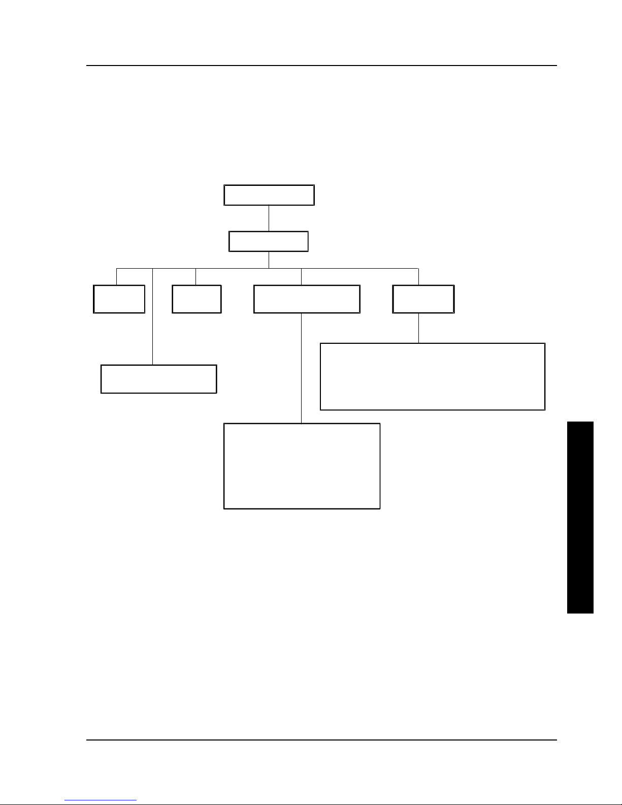
The SCU enables you to setup and configure the server using the menu driven items shown in figure 2-1.
Depending on the installed hardware and level of server security required, you might have to access one or
more of these items to properly configure the server.
Maintain System
Configuration Diskette
Learn About Configuring
Your Computer
Set Time
Configure
Computer
Main Menu
Welcome Screen
Step 1: Important EISA Configuration Information
Step 2: Add or Remove Boards
Step 3: View or Edit Details
Create a Backup SCI File
Load a Backup SCI File
Copy/Update CFG Files
Copy/Update SCI Files
Delete CFG Files
Delete SCI Files
Return to the Main Menu
Figure 2 - 1 SCU Main Menu Options

Utilities & ConfigurationUtilities & Configuration Digital PRIORIS XL ServerDigital PRIORIS XL Server
2020 MCS Logistics Engineering - NijmegenMCS Logistics Engineering - Nijmegen
P
R
I
O
R
I
S
X
L
Before Using the SCU
When familiar with utility programs and their uses, refer to the appropriate sections in this chapter to setup
or update the server’s configuration. Otherwise, carefully read and understand this chapter before
attempting to modify the server’s configuration settings.
Read any README files contained on the System Configuration Utility diskette for additional information.
In addition, have the following items readily available:
♦ A 1.44 MB formatted diskette.
♦ Configuration (CFG) files supplied with any installed EISA/PCI expansion boards.
Refer to the next section, “SCI Files and CFG Files”, for more information about CFG files.
♦ Kit installation instructions for any installed optional hardware.
SCI Files and CFG Files
The SCU creates a System Configuration Information (SCI) file each time you configure the server. This
SCI file can be used on other PRIORIS XL Servers that are equally configured and can serve as a backup
to the EISA configuration stored in NVRAM memory. The SCI file is maintained on the System
Configuration Utility diskette and has a default name SYSTEM.SCI.
Configuration (CFG) files contain main logic board, EISA, PCI, and ISA expansion board vital
characteristics and the server resources they require for proper operation. When installed additional EISA,
PCI, or ISA expansion boards, make sure to copy the CFG files (and overlays, if applicable) associated
with the expansion boards, to the System Configuration Utility diskette before attempting to configure the
server.
Refer to the option documentation for additional information.
Using the SCU
Use the SCU when experiencing problems with the hard disk and when it is necessary to reconfigure the
server. In addition, the SCU should be used to modify the configuration after you add or remove hardware,
or change server settings.
If this is the first time using the SCU, it is recommended to follow the procedures in the order given.
If this is a subsequent session, refer to the appropriate sections to update the server configuration.
To run the SCU, perform the following steps:
1) Install any optional hardware, for example disk drives, EISA expansion boards, and so on. to Chapter
3, “Service Procedures”.
2) Make a backup copy of the supplied System Configuration Utility diskette. Store the original in a
secure place and only use the backup copy when running the SCU. When unable to make a backup
copy, use the original diskette cautiously.
NOTE
It is recommended to not install the SCU or any of its utilities on a hard disk drive.
Running the SCU or any of its utilities from a hard disk drive might cause memory
conflicts between the SCU and application software. This specifically applies to
memory managers and Windows applications.

Digital PRIORIS XL ServerDigital PRIORIS XL Server Utilities & ConfigurationUtilities & Configuration
MCS Logistics Engineering - NijmegenMCS Logistics Engineering - Nijmegen 2121
P
R
I
O
R
I
S
X
L
3) Insert the backup System Configuration Utility diskette into drive A and then soft boot (reset) the
server. The SCU introductory screen appears.
NOTE
The SCU contains help pop-up screens for any selected menu item. Press [F1] at
anytime to display a help screen. Press [Esc] to remove a help screen.
4) Press [Enter] to display the SCU Welcome screen. If no configuration errors appear, the Welcome
screen displays information about the SCU. Press [Enter] to display the Main menu and proceed to
Step 6.
If a configuration error appears, the Welcome screen displays information about the error and tells to
reconfigure the server. Press [Enter] to display the Main menu, select the Configure
Computer
option, then select the View and Edit Details option. Make any changes as
indicated by the POST error message, and then select the Exit and Save option to end the SCU
session and boot the server so the changes take effect.
5) If applicable, select the Learn About Configuring The Computer option to familiarize
with the SCU.
6) If applicable, set the current server time and date using the Set Time and Set Date menu
options.
7) Using the Maintain System Configuration Diskette option, copy the CFG files
supplied with any EISA, PCI, or ISA expansion board.
8) Select the Configure Computer option to configure the server.
9) If applicable, select the Maintain System Configuration Diskette option to create,
change, or update SCI or CFG files.
10) To end the SCU session select the Exit From This Utility option.
11) If applicable, install the operating system and any application software.
Refer to the operating system and application software documentation for installation information.
Configure The Computer
when accessing this menu item for the first time, it is recommended to follow the menu items listed below
in the order given. If this is a subsequent session, refer to the appropriate menu item to update the server
configuration.
Step 1: Important EISA Configuration Information
Step 2: Add or remove boards
Step 3: View or edit details
Step 4: Examine required switches
Step 5: Save and Exit
Step 1: Important EISA Configuration Information
This menu item provides basic EISA configuration information and how it differs from ISA configuration.
These screens are available at any time during the configuration process by pressing [F1] and by selecting
EISA configuration from the help menu.
Step 2: Adding or Removing Boards
This menu item provides a list of boards and options in the configuration. You can add, move, and delete
boards from this list until it shows all the installed boards and options in the server, including the not yet
physically installed boards.

Utilities & ConfigurationUtilities & Configuration Digital PRIORIS XL ServerDigital PRIORIS XL Server
2222 MCS Logistics Engineering - NijmegenMCS Logistics Engineering - Nijmegen
P
R
I
O
R
I
S
X
L
The SCU automatically detects any EISA expansion boards installed on the server and configures the
server accordingly. The SCU does not automatically detect ISA expansion boards.
Step 3: View or Edit Details
This menu item allows to examine and change the setting of each function and the resource allocated for
those functions. When editing a function or resource in this step, you might have to change the switch or
jumper setting.
Step 4: Examine Required Switches
This menu item allows to view settings (switches and jumpers) that need to be manually set and software
drivers that need to be installed. These recommendations must be followed exactly, otherwise the server
will not work properly.
Step 5: Save and Exit
This menu item allows to exit the SCU program with or without saving the configuration settings.
Adding ISA Boards
Perform the following steps to add ISA boards to the server configuration:
1) Select "Step 2: Adding and Removing Boards", and update the list of boards and options to include
any ISA boards you are going to install in the server.
2) Select "Step 4: Examine Required Switches", to check the required switch and jumper settings of the
ISA boards.
3) Select "Step 5: Save and Exit," to save the configuration and exit the SCU.
4) Turn off the server and install the ISA boards.
CAUTION
Do not attempt to physically install boards while the server is turned on.
SCU and Setup Options
The following Tables list the options available in the BIOS Setup utility and in the SCU (View or Edit
details). Following this table are detailed descriptions of the options that need further explanation.
Use the keyboard function keys to help to select options, change values, and display help information.
NOTE
The ROM BIOS Setup utility, SETUP.EXE, and the SCU contain the same options as
those listed in the following Table. Digital recommends to use the SCU to configure
the server each time you add hardware, remove hardware, or change server settings.
Also, the language field in SETUP.EXE contains all the languages listed as possible
settings. The BIOS Setup utility does not. The BIOS Setup utility has English only.
Use the CD-ROM startup diskette to run UPGRADE.EXE to update the server’s BIOS
to one of the following languages: French, German, Spanish, or Italian.

Digital PRIORIS XL ServerDigital PRIORIS XL Server Utilities & ConfigurationUtilities & Configuration
MCS Logistics Engineering - NijmegenMCS Logistics Engineering - Nijmegen 2323
P
R
I
O
R
I
S
X
L
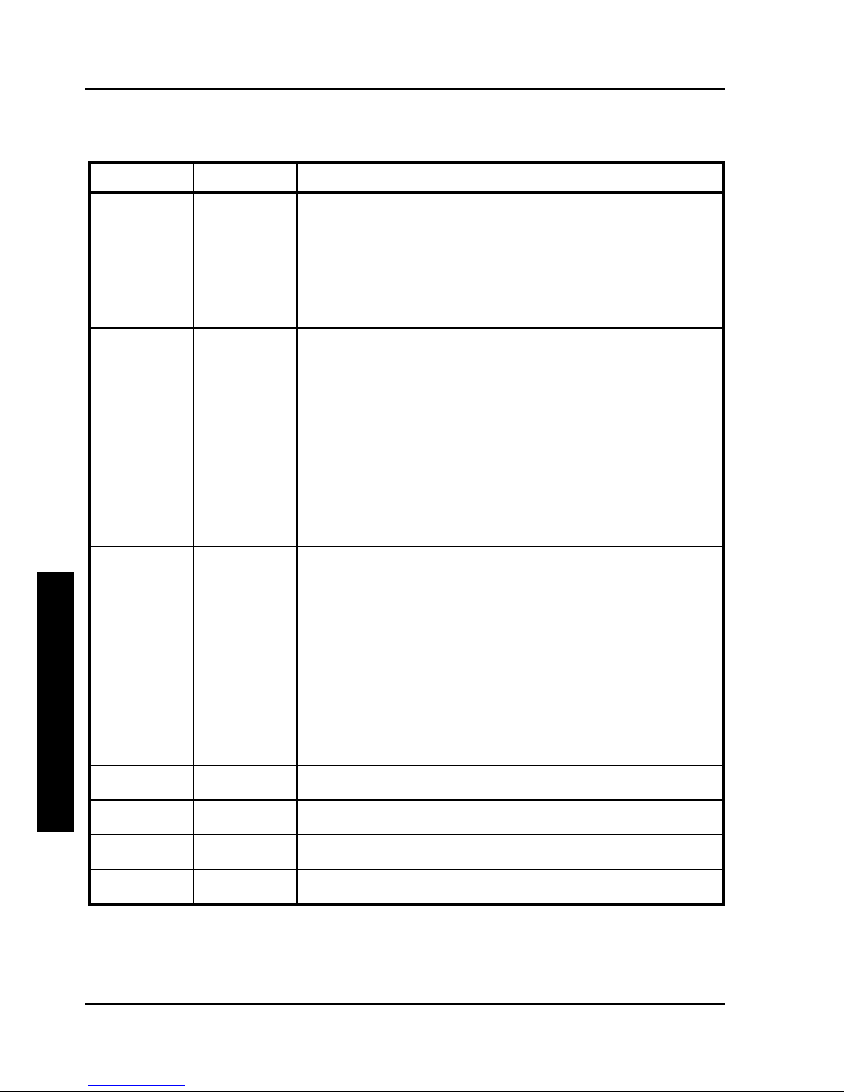
SCU and Setup Options
(continued)
Menu Fields
Settings
Comments
System time
Current time Displays the current time.
System date
Current date Displays the current date.
Language
English
Français
Deutsch
Italiano
Español
Nederlands
Sets the desired language.
Diskette A /
Diskette B
3.5", 1.44 MB
3.5", 2.88 MB
Not Installed
5.25", 360 KB
5.25", 1.2 MB
3.5", 720 KB
Sets the size and density of diskette drives.
Hard disk 1 /
hard disk 2
Drive types 1
through 49
Enables hard drive size and specific parameters from a predetermined
list of drive types. Drive types 2 and 3 or 48 and 49 are user definable
for hard drives not listed in the BIOS drive table.
(1)(2)
Base memory
Not user
selectable
displays the size of base (conventional) memory.
Extended
memory
Not user
selectable
Displays the current amount of extended memory.
(1)
Drive type 48 or 49 information is aliased to drive type 2 or 3 when application software does not recognize drive
types above 47
(2)
Auto-detection of IDE drive parameter is supported in types 2 and 3 and types 48 and 49 ( Refer to “Hard Disk
Drive 1/ Hard Disk Drive 2” later in this chapter).
Utilities & ConfigurationUtilities & Configuration Digital PRIORIS XL ServerDigital PRIORIS XL Server
2424 MCS Logistics Engineering - NijmegenMCS Logistics Engineering - Nijmegen
P
R
I
O
R
I
S
X
L
SCU and Setup Options
(continued)
Menu Fields
Settings
Comments
Video card
VGA or
EGA
CGA 40
Column
CGA 80
Column
Monochrome
Not Installed
Sets the video controller type.
Serial port 1
Enabled at:
3F8h-3FFh
(IRQ4)
Enabled at:
2F8h-2FFh
(IRQ3)
Enabled at:
3E8h-3EFh
(IRQ4)
Enabled at:
2E8h-2EFh
(IRQ3)
Disabled
Enables or disables any desired onboard serial port at the specified
address.
Serial port 2
Enabled at:
2F8h-2FFh
(IRQ3)
Enabled at:
3E8h-3EFh
(IRQ4)
Enabled at:
2E8h-2EFh
(IRQ3)
Disabled
Enabled at:
3F8h-3FFh
(IRQ4)
Enables or disables any desired onboard serial port at the specified
address.
Note: If the server is connected to a network, see the System
Administrator
Diskette drives
Enabled
Disabled
Enables or disables the onboard diskette drive controller. inte
Exchange
diskette drives
Disabled
Enabled
Allows to logically exchange physical diskette drive designations.
Diskettes write
protection
Disabled
Enabled
Enables or disables the selected diskette drive's write protect option.
IDE hard disk
drives
Enabled
Disabled
Enables or disables the onboard IDE disk drive controller.
Disable this option for SCSI operation.
Digital PRIORIS XL ServerDigital PRIORIS XL Server Utilities & ConfigurationUtilities & Configuration
MCS Logistics Engineering - NijmegenMCS Logistics Engineering - Nijmegen 2525
P
R
I
O
R
I
S
X
L
SCU and Setup Options
(continued)
Menu Fields
Settings
Comments
Keyboard
Installed
Not Installed
Enables or disables the keyboard when using the server as a network
server.
Note: You must initially setup the server with a keyboard.
NumLock at
boot
On
Off
Enables or disables the NumLock feature each time the server boots.
Password
System only
Setup only
System and
setup
Not Installed
Enables or disables a system power-on and/or BIOS setup password.
ROM based
setup
Enabled
Disabled
Enables or disables the ROM base setup utility.
CAUTION: When selecting Disabled, make sure the server is
bootable and there is a working copy of SETUP.EXE provided on the
supplied CD-ROM.
Mouse port
Enabled
Disabled
Enables the mouse port and assigns IRQ12.
Disables the mouse port and frees up IRQ12 for option use.
Parallel port
Enabled at:
378h-37Ah
(IRQ7)
Enabled at:
278h-27Ah
(IRQ7)
Enabled at:
3BCh-3BEh
(IRQ7)
Disabled
Extended mode
Compatible
mode
ECP mode
EPP mode
Enables or disables any desired onboard printer port at the specified
address.
Allows to select between standard printer and bi-directional
(extended) applications.
Allows to select between enhanced parallel port (EPP) and extended
capabilities port (ECP) applications.
HDD user
definable
types
Types 2 and 3
Types 48 and
49
The SCU allows types 2 and 3 or types 48 and 49 to be user
definable.
(3)(4)
HDD data
transfer
method
Standard PIO
Auto optimum
Allows for a standard, compatible data transfer method (one data
block per interrupt).
Allows the server’s BIOS to automatically set up the installed drive
for optimum performance (multiple data blocks per interrupt).
(3)
Auto-detection of IDE drive parameter is supported in types 2 and 3 and types 48 and 49
(Refer to “HardDisk Drive 1/ Hard Disk Drive 2” later in this chapter).
(4)
Some operating systems do not recognize hard disk drive types above 29.

Utilities & ConfigurationUtilities & Configuration Digital PRIORIS XL ServerDigital PRIORIS XL Server
2626 MCS Logistics Engineering - NijmegenMCS Logistics Engineering - Nijmegen
P
R
I
O
R
I
S
X
L
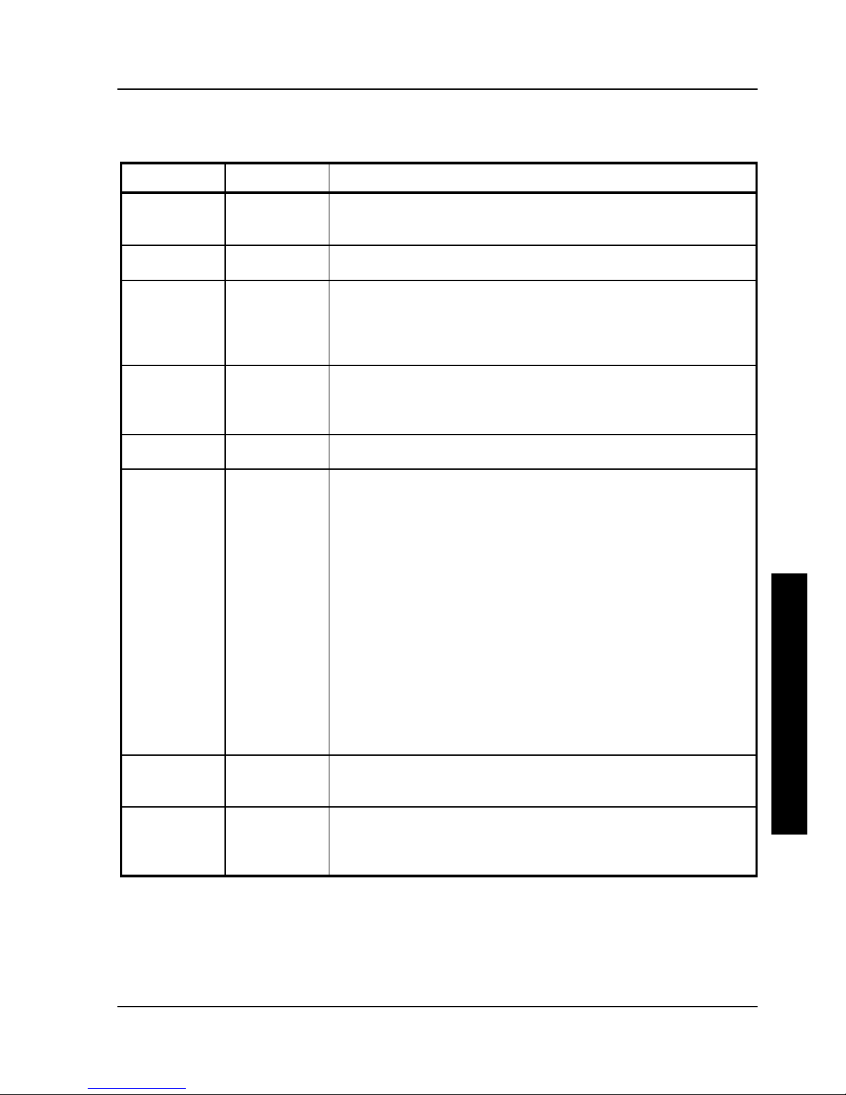
SCU and Setup Options
(continued)
Fields
Settings
Comments
Large drive
addressing
Standard
LBA convert
The drive’s cylinder/head/sector values are used by the BIOS and
operating system.
Allows the server’s BIOS to convert the logical cylinder/head/sector
used by the operating system to the drive’s cylinder/ head/ sector
value.
Boot from
diskette A
Enabled
Disabled
Enables or disables drive A as the logical boot device.
Boot from
hard disk C
Enabled
Disabled
Enables or disables drive C as the logical boot device.
CPU speed
Fast
Slow
Determines the speed used by the server each time you turn it on or
reboot.
Primary cache
Enabled
Disabled
Enables or disables the CPU's internal cache.
Secondary
cache
Enabled WT
Enabled WB
Disabled
Enables or disables the server’s external cache in WT or WB mode
(5)
.
Cache BIOS
ROM
Enabled
Disabled
Allows to enable or disable a caching request for the server’s BIOS.
Shadow video
ROM
Enabled
Disabled
Enables or disables the server’s shadow video ROM option.
Cache video
ROM
Enabled
Disabled
Enables or disables the server’s cache video ROM option.
Shadow 32K
at C8000
Enabled
Disabled
Enables or disables the server’s C8000 shadow option.
Shadow 32K
at D0000
Enabled
Disabled
Enables or disables the server’s D0000 shadow option.
Shadow 32K
at D8000
Enabled
Disabled
Enables or disables the server’s D8000 shadow option.
(5)
WB = Write-Back; WT = Write-Through

Digital PRIORIS XL ServerDigital PRIORIS XL Server Utilities & ConfigurationUtilities & Configuration
MCS Logistics Engineering - NijmegenMCS Logistics Engineering - Nijmegen 2727
P
R
I
O
R
I
S
X
L
SCU and Setup Options
(continued)
Fields
Settings
Comments
AT bus space
Disabled
F00000h, 1MB
E00000h, 1MB
E00000h, 2MB
C00000h, 4MB
F80000h,
.5MB
(6)
Memory hole not available.
Upper memory is contiguous.
Sets the memory hole at address F00000 with 1 MB memory
available.
Sets the memory hole at address E00000 with 1 MB memory
available.
Sets the memory hole at address E00000 with 2 MB memory
available.
Sets the memory hole at address C00000 with 4 MB memory
available.
Sets the memory hole at address F80000 with .5 MB memory
available.
512KB-640
KB mapping
Main memory
PCI/ISA
Allows to map the memory region between 512KB to 640KB to the
server’s main memory.
Allows to map the memory region between 512KB and 640KB to the
PCI or ISA bus.
(6)
i486 CPU only

Utilities & ConfigurationUtilities & Configuration Digital PRIORIS XL ServerDigital PRIORIS XL Server
2828 MCS Logistics Engineering - NijmegenMCS Logistics Engineering - Nijmegen
P
R
I
O
R
I
S
X
L
SCU and Setup Options
(continued)
Fields
Settings
Comments
PCI arbiter
priority
(7)
System
default
Pure rotating
EISA slot
Onboard
SCSI
CPU
PCI slot 3
PCI slot 2
PCI slot 1
Use system default according to host/EISA bridge used.
The priority rotates for all PCI devices.
EISA bridge has highest priority.
Onboard SCSI has highest priority.
CPU has highest priority.
PCI slot 3 has highest priority.
PCI slot 2 has highest priority.
PCI slot 1 has highest priority.
External
onboard
SCSI
Enabled
Disabled
Enables or disables onboard SCSI.
(7)
The PCI Arbiter Priority selection for factory installed PCI expansion boards should stay at the factory
default settings. Modifications to the default settings can cause server failure.

Digital PRIORIS XL ServerDigital PRIORIS XL Server Utilities & ConfigurationUtilities & Configuration
MCS Logistics Engineering - NijmegenMCS Logistics Engineering - Nijmegen 2929
P
R
I
O
R
I
S
X
L
SCU and Setup Options
(continued)
Fields
Settings
Comments
PCI device
(8)
Enable device:
Enabled
Disabled
Device IRQ:
None
IRQ3
IRQ4
IRQ5
IRQ6
IRQ7
IRQ9
IRQ10
IRQ11
IRQ12
IRQ14
IRQ15
Enable master:
Enabled
Disabled
Latency timer
Default
Allows to individually enable or disable each PCI slot and onboard
SCSI.
Allows to individually set an IRQ default for each PCI slot
CAUTION: Make sure the IRQ selected is not in conflict with any
main logic board resource or any expansion board.
Allows to enable or disable a PCI device that requires master
capability.
Allows to set the PCI latency timer (in PCI clocks) for each PCI
device.
(8)
The options listed are applicable to onboard SCSI and PCI slots 1, 2, and 3
Hard Disk Drive 1/Hard Disk Drive 2
This option allows to disable or configure the server for the IDE hard disk drives that are installed. You
can manually select drive types or use an auto-detect feature. To use the auto-detect feature, first select
either drive types 2 and 3 or drive types 48 and 49. Once selected, you are prompted to execute the autodetect feature by press the [Enter] key.
Base Memory
The main logic board reserves the first 1024 KB of address space for server use. Base memory (640 KB) is
first assigned to the operating system. The remaining 384 KB is assigned to either shadow main logic
board BIOS, video BIOS, or for other server use.
Base memory can be modified using the 512KB-640KB mapping field.

Utilities & ConfigurationUtilities & Configuration Digital PRIORIS XL ServerDigital PRIORIS XL Server
3030 MCS Logistics Engineering - NijmegenMCS Logistics Engineering - Nijmegen
P
R
I
O
R
I
S
X
L
ROM Based Setup
This option is often used by educational facilities that have public access to their servers. Disabling this
option prevents unauthorized personnel from changing any server’s configuration parameters.
Parallel Port and Serial Ports
The server logically assigns LPTx and COMx names to:
♦ Parallel ports in the address order 378h and 278h.
♦ Serial ports in the address order 3F8h, 2F8h, 3E8h, and 2E8h.
This occurs during each boot process. For example, When disabling the serial port that is assigned to 3F8h
as COM1, during the next boot cycle the server reassigns the name COM1 to the next enabled serial port in
the sequence.
Server Boot Management
The server comes from the factory with options Boot From Diskette A and Boot From Hard C enabled.
This means that each time you turn on or reset the server it attempts to first boot from diskette A and then
from hard disk drive C.
When changing the server’s boot sequence, be aware of the following:
Boot From Diskette A
Boot From Hard Disk C
Comments
Disabled
Disabled Allowed only if booting from a network
server.
Enabled
Disabled Server will only boot from diskette A
(1).
Disabled
Enabled Server will only boot from hard disk drive C.
(1)
When a second diskette drive installed, you can choose which one to boot from using the
"Exchange Diskette Drives" setup option.
 Loading...