

Digital Equipment PRIORIS MTE Service Maintenance Manual
MCS
LOGISTICS
ENGINEERING
Service
Maintenance
Manual
PRIORIS MTE
Server
K-MN-SD00000-04-JG00.A
P
R
I
O
R
I
S
M
T
E
NIJMEGEN
THE NETHERLANDS
Copyright Digital Equipment Corporation
All rights reserved
November 1995

November 1995
The information in this document is subject to change without notice and should not be construed as a
commitment by Digital Equipment Corporation.
Digital Equipment Corporation assumes no responsibility for any errors that might appear in this document.
The software, if any, described in this document is furnished under a license and may be used or copied only in
accordance with the terms of such license. No responsibility is assumed for the use or reliability of software or
equipment that is not supplied by Digital Equipment Corporation or its affiliated companies.
Restricted Rights: Use, duplication, or disclosure by the U.S. Government is subject to restrictions as set forth
in subparagraph (c) (1) (ii) of the Rights in Technical Data and Computer Software clause at DFARS 252.227-
7013.
P
Copyright Digital Equipment Corporation
R
All Rights Reserved
I
O
The following are trademarks of Digital Equipment Corporation:
PRIORIS and the Digital logo.
R
I
The following are third party trademarks:
S
MS-DOS and Windows and Windows NT and Windows NT Server are trademarks of Microsoft Corp.
Novell and Netware are trademarks of Novell, Inc.
SCO and Open Desktop are trademarks of The Santa Cruz Operation, Inc.
M
UNIX is a registered trademark of UNIX System Laboratories, Inc.
T
All other trademarks and registered trademarks are the property of their respective holders.
E
Created by:
MCS Logistics Engineering - Nijmegen
Printed in Ireland

Digital PRIORIS MTE Server Table of Contents
Table of Contents
PREFACE..............................................................................................................................................................7
CHAPTER 1 PRODUCT DESCRIPTION ...................................................................................................... 9
RODUCT INTRODUCTION.......................................................................................................................................9
P
Features..............................................................................................................................................................9
RODUCT MODELS INFORMATION........................................................................................................................10
P
Prioris MTE Server.......................................................................................................................................... 10
CHAPTER 2 SERVER UTILITIES & CONFIGURATION.......................................................................11
Before Using the Flash Upgrade Utility ..........................................................................................................11
Recovery Diskette............................................................................................................................................11
Using the Flash Upgrade Utility......................................................................................................................11
Setup ................................................................................................................................................................ 13
Accessing Setup...............................................................................................................................................13
When to Use Setup...........................................................................................................................................13
Exiting Setup....................................................................................................................................................14
ONFIGURING THE SERVER..................................................................................................................................14
C
The SCU .......................................................................................................................................................... 15
Before Using the SCU......................................................................................................................................16
SCI Files and CFG Files..................................................................................................................................16
Using the SCU .................................................................................................................................................16
Configure The Computer.................................................................................................................................17
Adding ISA Boards.......................................................................................................................................... 18
AND SETUP OPTIONS ....................................................................................................................................18
SCU
Additional Option Information........................................................................................................................23
System Base Memory......................................................................................................................................23
System Board Extended Memory....................................................................................................................23
User Definable Hard Disk Drive.....................................................................................................................23
Hard Drive 1/Hard Drive 2 .............................................................................................................................23
CPU Speed.......................................................................................................................................................23
CHAPTER 3 SERVICE PROCEDURES.......................................................................................................25
AFETY REQUIREMENTS.......................................................................................................................................25
S
ECOMMENDED TOOLS........................................................................................................................................26
R
Other Materials Needed...................................................................................................................................26
Special Tools Required.................................................................................................................................... 26
Remedial Diagnostic Test Software................................................................................................................26
ECO/FCO I
EMOVING THE SIDE PANEL.................................................................................................................................27
R
ERVER COMPONENTS..........................................................................................................................................28
S
XPANSION BOARDS.............................................................................................................................................29
E
AIN LOGIC BOARD JUMPERS ............................................................................................................................. 30
M
SVGA V
NFORMATION .....................................................................................................................................26
BIOS version information................................................................................................................................26
Main Logic Board Jumper Settings.................................................................................................................30
Main Logic Board Jumper Locations..............................................................................................................31
IDEO CARD (86C805) JUMPERS ............................................................................................................ 32
P
R
I
O
R
I
S
M
T
E
MCS Logistics Engineering - Nijmegen 3

Table of Contents Digital PRIORIS MTE Server
SVGA Video Card jumper settings.................................................................................................................32
SVGA Video Card jumper Locations ............................................................................................................. 32
OMPUTER MEMORY CONFIGURATIONS.............................................................................................................33
C
Memory Configurations .................................................................................................................................. 33
ART REMOVAL AND REPLACEMENT PROCEDURES...........................................................................................34
P
Removing Devices in the Lower Drive Bay Area........................................................................................... 34
Removing Devices in the Upper Drive Bay Area...........................................................................................36
Removing Fan / Speaker Assembly................................................................................................................. 37
Removing Main Logic Board..........................................................................................................................38
Removing Power Supply.................................................................................................................................39
Replacing the Server Battery...........................................................................................................................41
PGRADING PROCEDURES....................................................................................................................................42
U
Upgrading the CPU.......................................................................................................................................... 42
P
R
I
O
R
I
S
M
T
E
Secondary Cache Memory...............................................................................................................................43
Installing Video Memory upgrade on the SVGA Video Card........................................................................44
DDING MASS STORAGE DEVICES....................................................................................................................... 45
A
CHAPTER 4 TROUBLESHOOTING............................................................................................................ 47
I
NITIAL TROUBLESHOOTING ................................................................................................................................. 47
AND BOOT MESSAGES...............................................................................................................................48
POST
EEP CODES..........................................................................................................................................................49
B
Beep Codes for Fatal Errors ............................................................................................................................ 49
Beep Codes for Nonfatal Errors ...................................................................................................................... 51
ERVER TROUBLESHOOTING................................................................................................................................51
S
ISK DRIVE TROUBLESHOOTING .........................................................................................................................53
D
ONITOR TROUBLESHOOTING ............................................................................................................................. 53
M
LUS/FE ADVANCED DIAGNOSTICS ...............................................................................................................54
QAP
QAPlus/FE Error Messages............................................................................................................................. 54
CHAPTER 5 DEVICE MAPPING..................................................................................................................57
Computer Memory Map..................................................................................................................................57
I/O Address Map.............................................................................................................................................. 58
Computer Interrupt Levels .............................................................................................................................. 58
DMA Channel Assignment.............................................................................................................................. 59
CHAPTER 6 PASS / FAIL CRITERIA..........................................................................................................61
APPENDIX A SERVICE NOTES ................................................................................................................... 63
APPENDIX B USEFUL INFORMATION.....................................................................................................63
R
O
DOCUMENT FEEDBACK..............................................................................................................................67
PERSONAL NOTES ......................................................................................................................................... 69
R
4 MCS Logistics Engineering - Nijmegen
ELATED DOCUMENTATION.................................................................................................................................65
N-LINE BULLETIN BOARDS................................................................................................................................65
EADERS COMMENTS...........................................................................................................................................73

Digital PRIORIS MTE Server Product Description
Table of Figures
Figure 2 - 1 SCU Main Menu Options................................................................................................................15
Figure 3 - 1 Unlocking and Removing the Side Panels.......................................................................................27
Figure 3 - 2 Server Components..........................................................................................................................28
Figure 3 - 3 PRIORIS MTE Server Expansion Board Slots............................................................................... 29
Figure 3 - 4 Main Logic Board Jumper Locations..............................................................................................31
Figure 3 - 5 SVGA Video Card Jumper Locations.............................................................................................32
Figure 3 - 6 Main Logic Board Memory Banks locations..................................................................................33
Figure 3 - 7 Removing the Lower Drive Bay Assembly.....................................................................................34
Figure 3 - 8 Removing the Lower Drive Bay Devices........................................................................................35
Figure 3 - 9 Removing a Device from the Second Drive Bay.............................................................................36
Figure 3 - 10 Removing the Fan/Speaker Assembly........................................................................................... 37
Figure 3 - 11 Removing the Main Logic Board..................................................................................................38
Figure 3 - 12 Removing the ON/OFF Switch .....................................................................................................39
Figure 3 - 13 Removing the power plug..............................................................................................................39
Figure 3 - 14 Removing the screws at the rear....................................................................................................40
Figure 3 - 15 Removing the Power Supply .........................................................................................................40
Figure 3 - 16 Installing the Server Battery..........................................................................................................41
Figure 3 - 17 Upgrading the CPU........................................................................................................................42
Figure 3 - 18 Cache Memory Upgrade................................................................................................................43
Figure 3 - 19 Installing Video Memory upgrade.................................................................................................44
P
R
I
O
R
I
S
M
T
E
MCS Logistics Engineering - Nijmegen 5


Digital PRIORIS MTE Server Product Description
Preface
The Digital PRIORIS MTE Server Service Maintenance Manual is a troubleshooting guide that can be used
for reference when servicing the PRIORIS MTE Server series.
Digital Equipment Corporation reserves the right to make changes to the Digital PRIORIS MTE Server
without notice. Accordingly, the diagrams and procedures in this document may not apply to the computer(s) to
be serviced since many of the diagnostic tests are designed to test more than one product.
CAUTION
Digital recommends that only A+ certified engineers attempt to repair this equipment.
All troubleshooting and repair procedures are detailed to support subassembly/module
level exchange. Because of the complexity of the indivual boards and subassemblies, no
one should attempt to make repairs at component level or to make modifications to any
printed wiring board. Improper repairs can create a safety hazard. Any indications of
component replacement or printed wiring board modifications may void any warranty or
exchange allowances.
P
R
I
O
R
I
S
M
T
E
MCS Logistics Engineering - Nijmegen 7


Digital PRIORIS MTE Server Product Description
Chapter 1 Product Description
Product Introduction
The Prioris MTE servers are a family of high-performance, i486 processor-based, personal computers equipped
with the latest microprocessor technology. They can be used as stand-alone computers, as clients, or as servers
in a network environment.
Features
♦ Upgradable system comptible P24T ZIF socket
♦ 8 MB system RAM, Upgradable to 128 MB on motherboard
♦ 128 KB external cache memory (direct-mapped), expandable to 256 KB
♦ On-board IDE controller
♦ SVGA video card, 1 MB, ISA included
♦ Supports up to five storage devices
♦ Five full-size, 32 bit EISA slots and one slot which is either a VL-bus VESA slot or an EISA slot (for a
maximum of six EISA slots)
♦ Interfaces: two serial (RS-3232C) and one parallel (Centronics)
♦ Autosensing Power supply, 260 Watt
P
R
I
O
R
I
S
M
T
E
MCS Logistics Engineering - Nijmegen 9
Product Description Digital PRIORIS MTE Server
Product Models Information
Prioris MTE Server
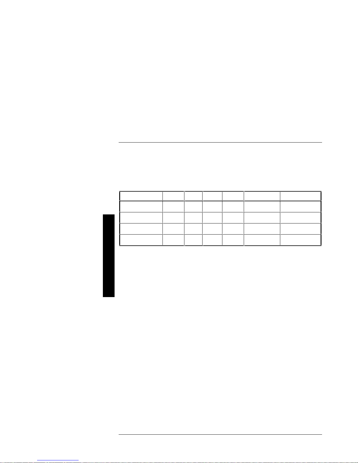
Model CPU RAM Cache FDD HDD CD-ROM
P
R
I
O
R
I
S
M
T
E
FR-PCT73-BV
FR-PCT73-BB
FR-PCT73-LE
FR-PCT74-BV
486DX2/
66 MHz
486DX2/
66 MHz
486DX2/
66 MHz
486DX4/
100 MHz
8 MB 128 KB 1.44 MB None None
16 MB 128 KB 1.44 MB 1 GB SCSI-2 Standard
16 MB 128 KB 1.44 MB 535 MB SCSI-2 600 MB double
speed
8 MB 128 KB 1.44 MB None None
10 MCS Logistics Engineering - Nijmegen

Digital PRIORIS MTE Server Server Utilities & configuration
Chapter 2 Server Utilities & Configuration
Before Using the Flash Upgrade Utility
When not familiar with utility programs and their uses, carefully read and understand the information
contained in this chapter before attempting to use the Flash Upgrade utility.
Have the following items available:
♦ Blank formatted diskette.
♦ Utilities diskette (supplied with the system).
♦ System Configuration Utility diskette (supplied with the system).
P
R
I
O
R
I
S
M
T
E
Recovery Diskette
A recovery diskette should always be prepared before attempting to upgrade the BIOS. This diskette contains a
BIOS image and a program to load the image into flash memory. If a problem occurs during the programming
of BIOS into flash memory, a siren sounds when the Server is turned on. Insert the recovery diskette into drive
A or B and the original BIOS is put back in flash memory.
Using the Flash Upgrade Utility
Perform the following steps to create a recovery diskette, update the BIOS in the flash memory, and compare
the BIOS image file to the flash memory:
1) Insert the Utilities diskette (supplied with the system) into drive A.
2) Turn on the computer.
MCS Logistics Engineering - Nijmegen 11

Server Utilities & configuration Digital PRIORIS MTE Server
3) At the MS-DOS prompt, type a:upgrade, and then press [Enter]. This invokes the Flash Upgrade utility.
The following menu items appear on the screen:
Make Recovery Diskette from Flash
Make Recovery Diskette from Image File
Upgrade Flash from Image File
Save Flash to Image File
Compare Flash to Image File
BIOS Information
Exit
For on-line help, press [F1].
4) Select the Make Recovery Diskette from Flash menu option. The message, "Please
select the diskette drive that will be used to create a Flash
P
R
I
O
R
I
S
M
T
E
Recovery Diskette, or select "Cancel" to abort", appears on the screen.
5) Press the [Tab] or up and down arrow keys to highlight the desired diskette drive, then press [Enter].
Drive A is the default diskette drive. The message, "Insert a formatted diskette into
drive A. The contents of this diskette will be lost! and replaced
with system recovery software and the specified BIOS image. Select
"Continue" to start writing the recovery diskette, or "Cancel" to
abort," appears on the screen.
6) Insert a blank (formatted) diskette in drive A, and select Continue to proceed with the creation of a
recovery diskette. A message window notifies when it completes. Press any key to continue.
7) Remove the recovery diskette from drive A and store it in a safe place.
8) Insert the Utilities diskette in drive A.
9) Select the Upgrade Flash from Image File menu option. You are prompted to select the
BIOS image file to program into flash memory.
10) Press [Enter] to list a directory of .BIN (BIOS image) files. Select the desired image file.
The message, "The old BIOS will now be replaced by the new BIOS image.
Select "Program" to start, or "Cancel" to abort. Keep in mind that
programming a new BIOS into Flash memory requires a fair amount of
power. "If you are running on battery power you should have a full
charge!" appears on the screen.
11) Press [Enter] to proceed with the programming of the new BIOS into flash memory.
The message, "DO NOT TURN OFF THE POWER", appears on the screen.
The flash memory is erased, then the new BIOS is copied. Depending on the size of flash memory, the
programming takes 20-40 seconds. When the programming of the flash BIOS is complete, a message
briefly appears on the screen, then the system attempts to reboot.
12) Remove the Utilities diskette to allow the system to reboot without error. If an error occurs the flash
memory is corrupted and a siren sounds when the computer is rebooted. If this occurs, insert the recovery
diskette into drive A or B and the original BIOS is put back in flash memory.
If the computer does not reboot and the siren does not sound, turn off the computer. Set the main logic
board jumper J53 to recovery mode This procedure forces a BIOS recovery process. Refer to “Main
Logic board Jumper Locations”.
13) Insert the Utilities diskette into drive A, invoke the Flash Upgrade utility and select the Compare
Flash to Image File menu option. The message, "Select BIOS Image File Name
to compare against flash memory," appears on the screen.
14) Press [Enter] to display a list of .BIN (BIOS image) files. Select the .BIN file to be compared with the
flash memory. A message window displays whether the flash memory contains the same BIOS as the disk
file. Press any key to continue.
12 MCS Logistics Engineering - Nijmegen

Digital PRIORIS MTE Server Server Utilities & configuration
15) If applicable, select the Save Flash to Image File menu option. This option reads BIOS out
of flash memory and stores it on a disk file. A valid image file can be used with other upgrade commands
that need an image file. The default name for the image file is DEFAULT.BIN. You can type in a
different file name if you do not want to use the default name.
16) Select the Quit menu option to exit the Flash Upgrade utility.
17) Run the System Configuration Utility (SCU) to make sure the ROM Based Setup option is enabled.
Setup
Setup allows to select and permanently store information about the computer's installed hardware and software
in the battery-backed memory of the CMOS RAM. This information takes effect each time the computer boots
and can be changed each time you run Setup.
Accessing Setup
Use one of the following methods to access Setup:
♦ ROM Based Setup—Boot the computer and allow the POST to complete, then press [F1] to display the
initial Setup screen.
♦ SETUP.COM—Insert the Utilities diskette in drive A. At the MS-DOS prompt, type a:setup. The initial
Setup screen appears.
NOTE Values specified in Setup are overwritten when the System Configuration Utility (SCU)
is run, therefore do not use Setup to modify most configuration settings
next section, "When to Use Setup"
to make changes to the computer's configuration.
, for specific situations where Setup should be used
. Refer to the
P
R
I
O
R
I
S
M
T
E
When to Use Setup
Since Setup values are overwritten by the SCU, it is recommended that Setup is used only if you:
♦ Need to enable a diskette drive.
♦ Do not have access to a diskette drive.
♦ Have only Industry Standard Architecture (ISA) expansion boards and will not be using the SCU.
♦ Need to disable or enable the ROM Based Setup option.
NOTE If Setup is used to make changes to the computer configuration, it is recommended to
MCS Logistics Engineering - Nijmegen 13
use the ROM Based Setup. Use SETUP.COM (on the Utilities diskette) only when
enabling of the ROM Based Setup option is desired.
Server Utilities & configuration Digital PRIORIS MTE Server
Exiting Setup
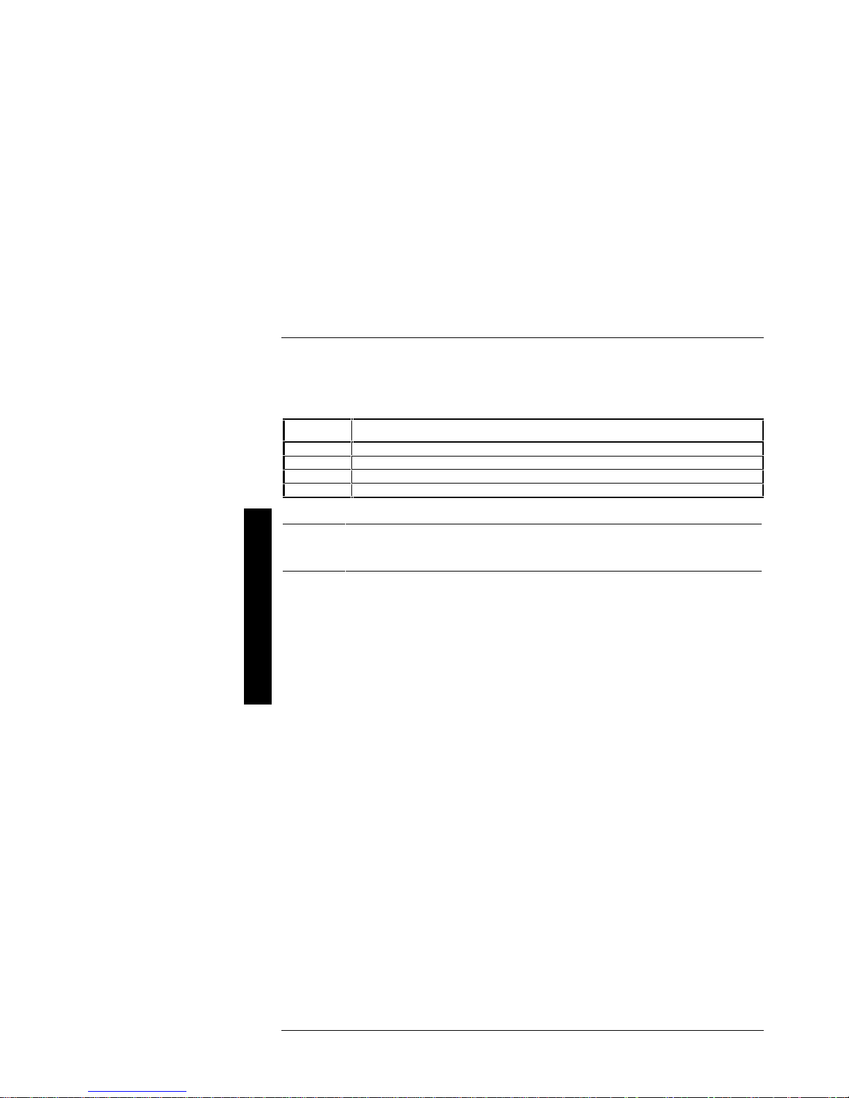
To exit Setup, press [Esc] to display the following menu options, then press one of the function keys indicated:
Key Function
Esc
F4
F5
F6
Continue with SETUP.
Save values- exit SETUP- and reboot.
Load default values for all pages.
Abort SETUP without saving values.
P
NOTE If the POST fails to complete successfully, access Setup and check all settings.
R
I
O
If necessary, press [F5] to load factory default values. Loading these values allows
the computer to operate with a minimum of options.
R
I
Configuring The Server
S
This chapter provides detailed information on how to configure the server using the System Configuration
M
Utility (SCU). Digital recommends to use the SCU to initially configure the server and each time you add
hardware, remove hardware, or change server settings.
T
If the server was delivered with factory-installed hardware and software, the server has already been
E
configured.
14 MCS Logistics Engineering - Nijmegen
Digital PRIORIS MTE Server Server Utilities & configuration
The SCU
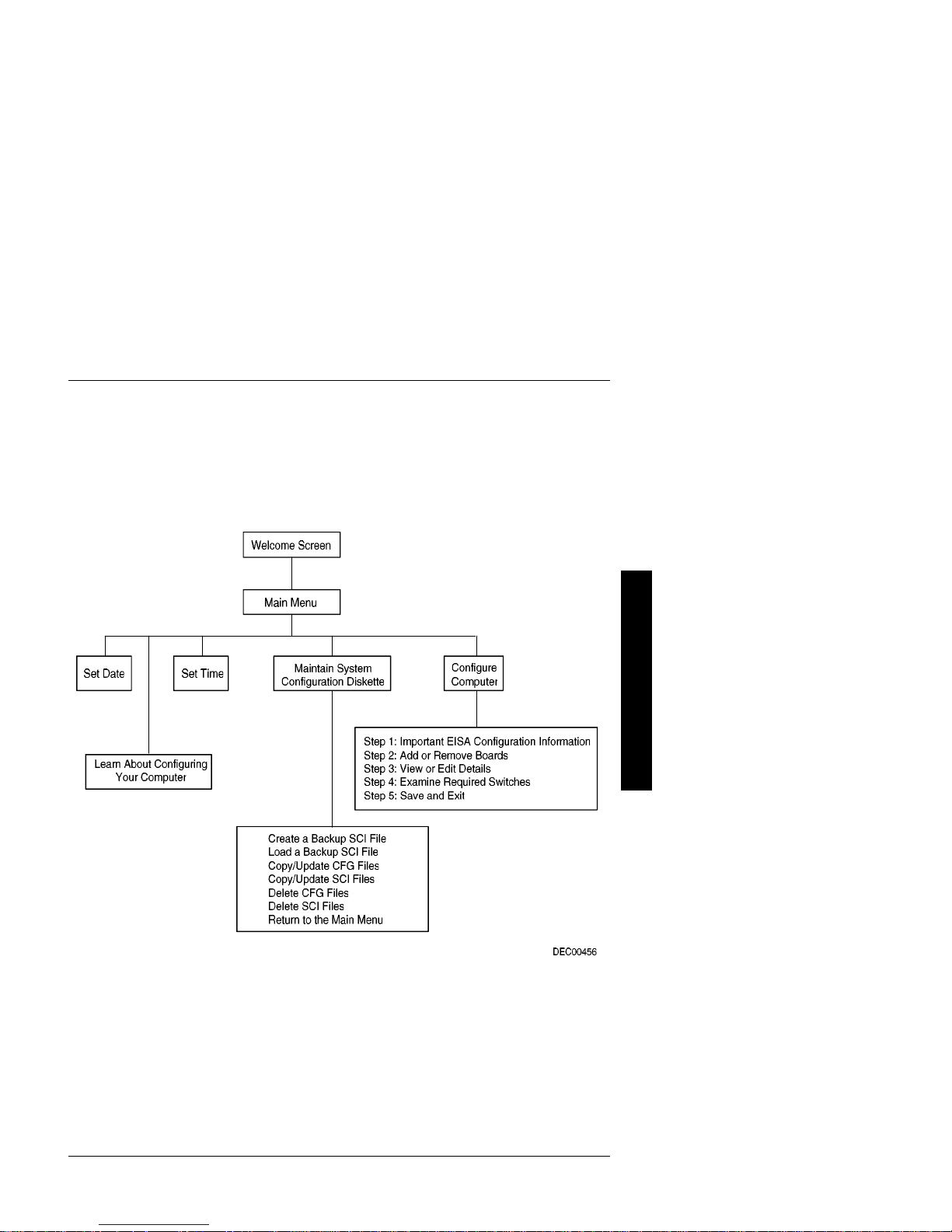
The SCU enables to setup and configure the server using the menu driven items shown in figure 2 - 1.
Depending on the installed hardware and level of server security required, you might have to access one or
more of these items to properly configure the server.
P
R
I
O
R
I
S
M
T
E
Figure 2 - 1 SCU Main Menu Options
MCS Logistics Engineering - Nijmegen 15

Server Utilities & configuration Digital PRIORIS MTE Server
Before Using the SCU
When familiar with utility programs and their uses, refer to the appropriate sections in this chapter to setup or
update the server’s configuration. Otherwise, carefully read and understand this chapter before attempting to
modify the server’s configuration settings.
Read any README files contained on the System Configuration Utility diskette for additional information.
In addition, have the following items readily available:
♦ A 1.44 MB formatted diskette.
♦ Configuration (CFG) files supplied with any installed EISA/PCI expansion boards.
Refer to the next section, "SCI Files and CFG Files", for more information about CFG files.
P
♦ Kit installation instructions for any installed optional hardware.
R
I
O
SCI Files and CFG Files
R
The SCU creates a System Configuration Information (SCI) file each time the server is configured. This SCI
I
file can be used on any PRIORIS MTE Server that are equally configured and can serve as a backup to the
S
EISA configuration stored in NVRAM memory. The SCI file is maintained on the System Configuration
Utility diskette and has a default name of SYSTEM.SCI.
Configuration (CFG) files contain main logic board, EISA, PCI, and ISA expansion board vital characteristics
M
and the server resources they require for proper operation. When additional EISA, PCI, or ISA expansion
T
boards are installed, make sure to copy the CFG files (and overlays, if applicable) associated with the
expansion boards, to the System Configuration Utility diskette before attempting to configure the server.
E
Refer to the option documentation for additional information.
Using the SCU
Use the SCU when experiencing problems with the hard disk and need to reconfigure the server. In addition,
the SCU should be used to modify the configuration after you add or remove hardware, or change server
settings.
If this is the first time using the SCU, it is recommended that to follow the procedures in the order given.
If this is a subsequent session, refer to the appropriate sections to update the server configuration.
To run the SCU, perform the following steps:
1) Install any optional hardware, for example disk drives, EISA expansion boards, and so on. Refer to
2) Make a backup copy of the supplied System Configuration Utility diskette. Store the original in a secure
NOTE It is recommended not to install the SCU or any of its utilities on a hard disk drive.
16 MCS Logistics Engineering - Nijmegen
Chapter 3, "Service Procedures ".
place and only use the backup copy when running the SCU. When unable to make a backup copy, use
the original diskette cautiously.
Running the SCU or any of its utilities from a hard disk drive might cause memory
conflicts between the SCU and application software. This specifically applies to
memory managers and Windows applications.

Digital PRIORIS MTE Server Server Utilities & configuration
3) Insert the backup System Configuration Utility diskette into drive A and then soft boot (reset) the server.
The SCU introduction screen appears.
NOTE The SCU contains help pop-up screens for any selected menu item. Press [F1] at
anytime to display a help screen. Press [Esc] to remove a help screen.
4) Press [Enter] to display the SCU Welcome screen. If no configuration errors appear, the Welcome screen
displays information about the SCU. Press [Enter] to display the Main menu and proceed to Step 6.
If a configuration error appears, the Welcome screen displays information about the error and tells to
reconfigure the server. Press [Enter] to display the Main menu, select the Configure Computer
option, then select the View and Edit Details option. Make any changes as indicated by the
POST error message, and then select the Exit and Save option to end the SCU session and boot the
server so the changes take effect.
5) If applicable, select the Learn About Configuring The Computer option to get familiar
with the SCU.
6) If applicable, set the current server time and date using the Set Time and Set Date menu options.
7) Using the Maintain System Configuration Diskette option, copy the CFG files supplied
with any EISA, PCI, or ISA expansion board.
8) Select the Configure Computer option to configure the server.
9) If applicable, select the Maintain System Configuration Diskette option to create,
change, or update SCI or CFG files.
10) To end the SCU session select the Exit From This Utility option.
11) If applicable, install the operating system and any application software.
Refer to the operating system and application software documentation for installation information.
Configure The Computer
P
R
I
O
R
I
S
M
T
E
When accessing this menu item for the first time, it is recommended to follow the menu items listed below in
the order given. If this is a subsequent session, refer to the appropriate menu item to update the server
configuration.
Step 1: Important EISA Configuration Information
Step 2: Add or remove boards
Step 3: View or edit details
Step 4: Examine required switches
Step 1: Important EISA Configuration Information
This menu item provides basic EISA configuration information and how it differs from ISA configuration.
These screens are available at any time during the configuration process by pressing [F1] and by selecting
EISA configuration from the help menu.
Step 2: Adding or Removing Boards
This menu item provides a list of boards and options in the configuration. You can add, move, and delete
boards from this list until it shows all the installed boards and options in the server, including the boards not yet
physically installed.
The SCU automatically detects any EISA expansion boards installed on the server and configures the server
accordingly. The SCU does not automatically detect ISA expansion boards.
MCS Logistics Engineering - Nijmegen 17
Step 5: Save and Exit

Server Utilities & configuration Digital PRIORIS MTE Server
Step 3: View or Edit Details
This menu item allows to examine and change the setting of each function and the resource allocated for those
functions. When editing a function or resource in this step, you might have to change the switch or jumper
setting.
Step 4: Examine Required Switches
This menu item allows to view settings (switches and jumpers) that need to be manually set and software
drivers that need to be installed. These recommendations must be followed exactly, otherwise the server will
not work properly.
Step 5: Save and Exit
P
This menu item allows to exit the SCU program with or without saving the configuration settings.
R
I
Adding ISA Boards
O
R
Perform the following steps to add ISA boards to the server configuration:
I
1) Select "Step 2: Adding and Removing Boards", and update the list of boards and options to include any
S
M
T
E
ISA boards to be installed in the server.
2) Select "Step 4: Examine Required Switches", to check the required switch and jumper settings of the ISA
boards.
3) Select "Step 5: Save and Exit", to save the configuration and exit the SCU.
4) Turn off the server and install the ISA boards.
CAUTION
Do not attempt to install boards while the server is turned on.
SCU and Setup Options
The following tables list the options that are available in the BIOS Setup utility and in the SCU (View or Edit
details). Use the keyboard function keys to help select options, change values, and display help information.
NOTE The ROM BIOS Setup utility and the SCU contain the same options as those listed.
18 MCS Logistics Engineering - Nijmegen
Digital recommends to use the SCU to configure the server each time you add
hardware, remove hardware, or change server settings.
Digital PRIORIS MTE Server Server Utilities & configuration
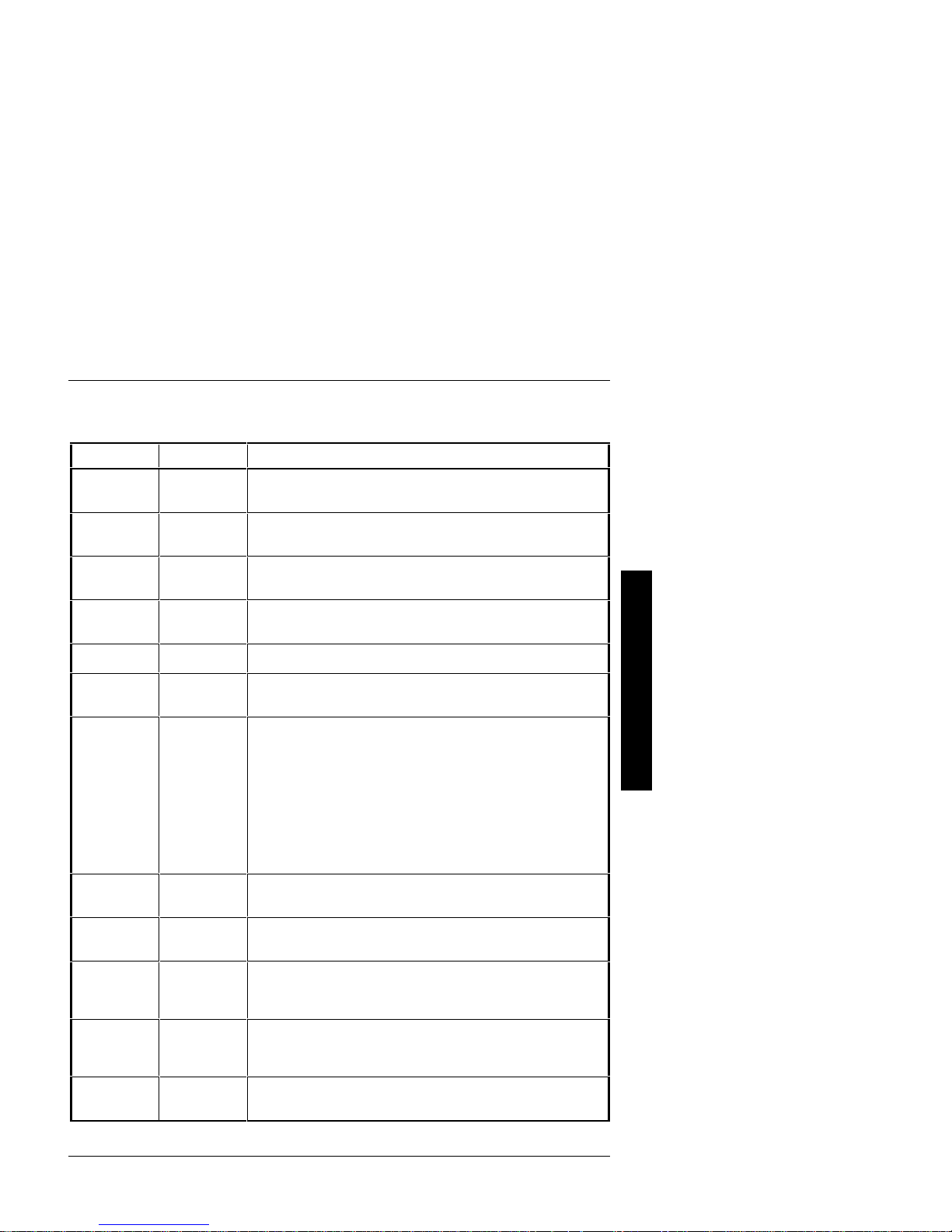
SCU and Setup Options (continued)
Menu Fields Settings Comments
System
Processor
Type
System
Processor
Clock
System Base
Memory
System
Extended
Memory
System BIOS
Onboard
Diskette
Controller
Diskette
Drive A
Diskette
Drive B
Exchange
Diskette
Drives
Boot from
Diskette Drive
A
Onboard IDE
Hard Disk
Controller
Hard Drive 1
Hard Drive 2
User Definable
Hard Drives
Not user
selectable
Not user
selectable
Not user
selectable
(640 KB)
Not user
selectable
Not user
selectable
Enabled
Disabled
3½-inch
720 KB
3½-inch
1.44 MB
3½-inch
2.88 MB
5¼-inch
360 KB
5¼-inch
1.2 MB
Not installed
Enabled
Disabled
Enabled
Disabled
Enabled
Disabled
Drive types
1-49
Not Installed
Type
48 and 49
Type 2 and 3
Displays the currently installed processor type.
Displays the currently installed processor clock speed.
Sets the size of base (conventional) memory.
Displays the current amount of extended memory.
Displays the BIOS version.
Enabled when it is the primary interface to the diskette drive.
Disabled if an external diskette controller performs the interfacing to the
diskette drives.
Selects the size and density of 3½-inch diskette drives.
Selects the size and density of 5¼-inch diskette drives.
Disables the selected diskette drive.
Enables the logical exchange of physical diskette drive designations.
Disables the logical exchange of physical diskette drives.
Enables diskette drive A as a logical boot device.
Disables diskette drive A as a logical boot device.
Enables the on-board IDE controller interface; the controller can be used
as the primary interface to the bootable hard disk.
Disables the on-board IDE controller when it is not being used and
another disk controller is the primary interface to the bootable drive.
Enables hard drive size and specific parameters from a predetermined list
of drive types. Drive types 2 and 3 or 48 and 49 are user definable for
hard drives not listed in the BIOS drive table.
Disables the selected hard disk.
See Hard Drive 1 and Hard Drive 2.
P
R
I
O
R
I
S
M
T
E
MCS Logistics Engineering - Nijmegen 19
Server Utilities & configuration Digital PRIORIS MTE Server
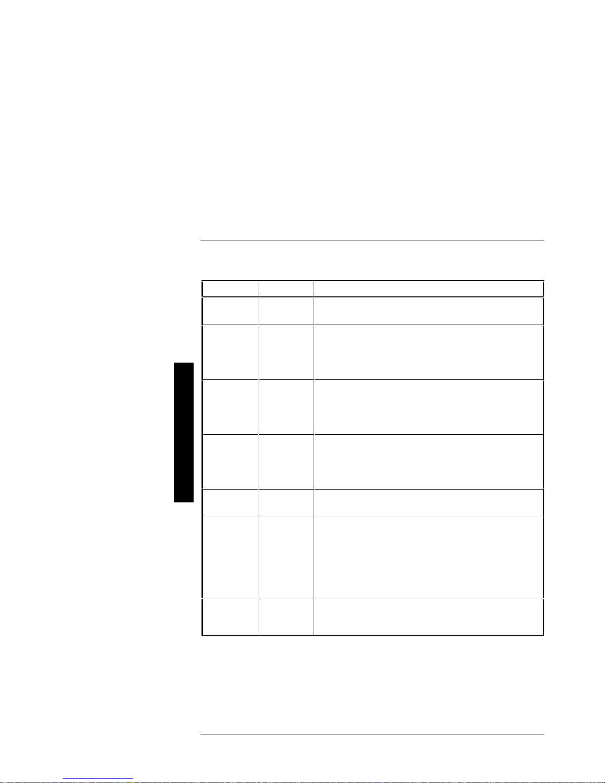
SCU and Setup Options (continued)
Menu Fields Settings Comments
P
R
I
O
R
I
S
M
T
E
Boot from
Hard Disk
Drive C
Serial Port 1
Serial Port 2
Parallel Port
Video Type
Shadow Video
BIOS ROM
Shadow
C8000hCFFFFh
Shadow
D0000hD7FFFh
Shadow
D8000hDFFFFh
Primary
Cache Control
Enabled
Disabled
Enabled at
COM1, COM2,
COM3, COM4
Disabled
Enabled at base
address 378h,
278h, 3BCh
(compatible)
Disabled
VGA or EGA
CGA 40
columns
CGA 80
columns
Monochrome
Enabled
Disabled
Enabled
Disabled
Enabled
Disabled
Enables IDE drive C as a logical boot device.
Disables IDE drive C as a logical boot device.
Enables any desired on-board serial port.
Disables any desired on-board serial port at the specified base address.
Enables on-board printer port.
Disables any desired on-board printer port.
Allows to specify the type and mode of the video module that is installed.
Enables the shadowing request for Video BIOS ROM. When shadowing
of this area is enabled, caching is also enabled.
Disables the shadowing request for Video BIOS ROM.
Disables the shadowing request for optional ROM.
Enables the shadowing request for optional ROM.
Enables the microprocessor's internal (primary) cache. Enabling the
cache controller significantly improves computer performance by
reducing the average number of wait states seen by the microprocessor.
Disables the microprocessor's internal cache.
20 MCS Logistics Engineering - Nijmegen
Digital PRIORIS MTE Server Server Utilities & configuration
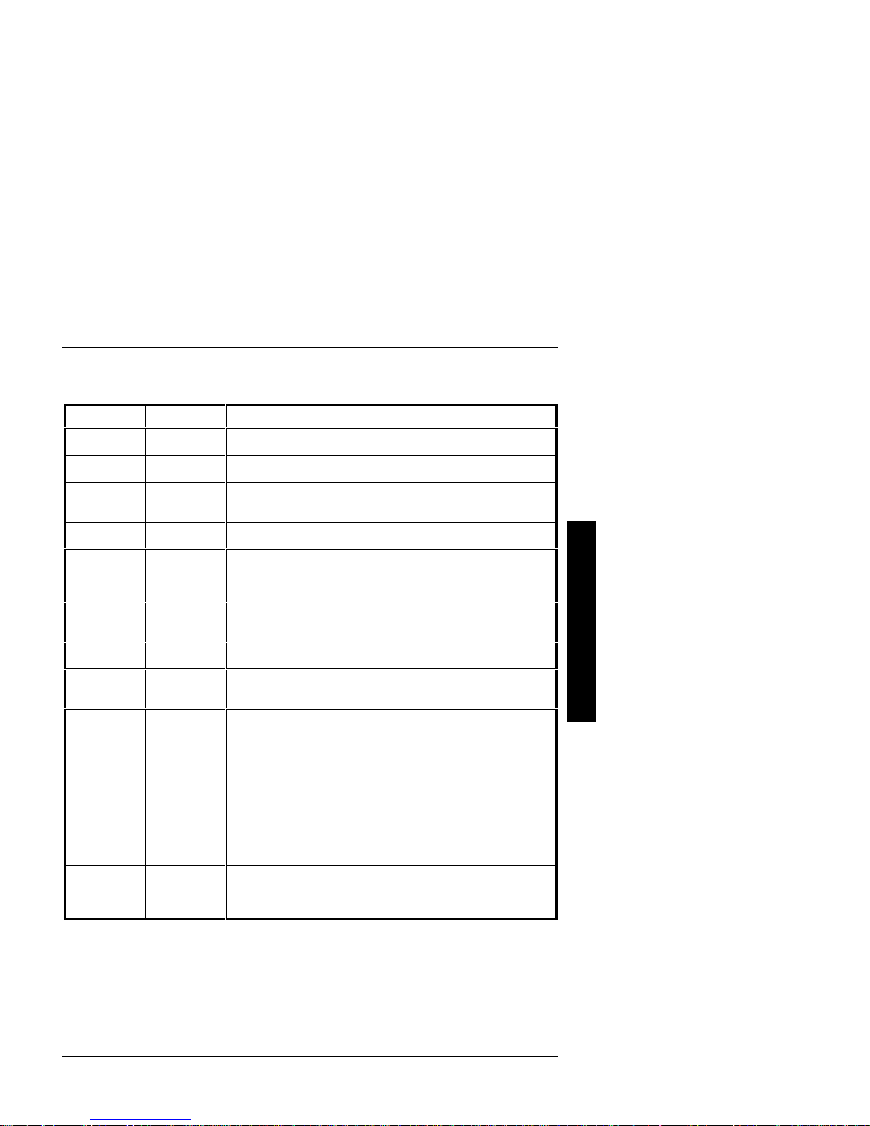
SCU and Setup Options (continued)
Field Settings Comments
Secondary
Cache Control
Cache System
BIOS ROM
Power-On
Password
CPU Speed
NumLock at
Boot
Keyboard
Concurrent
Refresh
Reserved
System
Resources
86C805/928
GUI
Accelerator
Vertical
Retrace
Interrupt
Enabled
Disabled
Enabled
Disabled
Not Installed
Installed
Fast
Slow
Off
On
Not Installed
Installed
Disabled
Enabled
Not user
selectable
Not Installed
Graphics:
Color or Mono
Graphics:
Color
Graphics:
Mono
Text:
Color or Mono
Text: Color
Text: Mono
Interrupt
Enabled
Interrupt
Disabled
Enables the secondary (external) cache (if installed).
Disables the secondary cache.
Enables the caching request for system BIOS ROM.
Disables the caching request for system BIOS ROM.
A power-on password is not set.
A power-on password is set. You are prompted for the password when
the system is rebooted.
CPU operates at its full rated speed.
CPU operates at 8 MHz.
Turns off the keyboard's NumLock feature each time you boot the
computer.
Turns on the keyboard's NumLock feature each time you boot the
computer.
Set this option to Not Installed if you plan to operate the computer as a
network server without a keyboard installed.
Enables to check the keyboard during the POST.
Disables the concurrent refresh feature of the chip set.
Enables the concurrent refresh feature of the chip set.
Configuration File and Overlay Version.
Select Not Installed only if the VID 805/928 VGA module GUI
Accelerator is not going to be installed with the system.
Allows to specify the presence of the VID 805/928 VGA module.
Enables the resource allocation at vertical retrace interrupt - IRQ 2(9).
Disables the resource allocation at vertical retrace interrupt - IRQ 2(9).
P
R
I
O
R
I
S
M
T
E
MCS Logistics Engineering - Nijmegen 21

Server Utilities & configuration Digital PRIORIS MTE Server
SCU and Setup Options (continued)
Field Settings Comments
P
R
I
O
R
I
S
Monitor Type
(805)
640x480@
60Hz/NI
640x480@
72Hz/NI
800x600@
60Hz/NI
800x600@
72Hz/NI
800x600@
56Hz/NI
1024x768@
43Hz/I
1024x768@
60Hz/NI
1024x768@
72Hz/NI
1280x1024@
43Hz/I
Enables to select the resolution and refresh rate (vertical
synchronization) of the optional local bus VGA module. This setting
should match the capabilities of the monitor (see the monitor
documentation for specifications).
M
T
E
Monitor Type
(928)
640x480@
60Hz/NI
640x480@
72Hz/NI
800x600@
60Hz/NI
800x600@
72Hz/NI
800x600@
56Hz/NI
1024x768@
43Hz/I
1024x768@
60Hz/NI
1024x768@
72Hz/NI
1280x1024@
43Hz/I
1280x1024@
60Hz/NI
1600x1280@
43Hz/I
22 MCS Logistics Engineering - Nijmegen
 Loading...