

Digital Equipment Prioris HX MP User Manual

Prioris HX MP Server
User's Guide
Part Number: ER-890WW-UA. A01
Digital Equipment Corporation

June 1995
The information in this document is subject to change without notice and should
not be construed as a commitment by Digital Equipment Corporation.
Digital Equipment Corporation assumes no responsibility for any errors that
might appear in this document.
The software, if any, described in this document is furnished under a license and
may be used or copied only in accordance with the terms of such license. No
responsibility is assumed for the use or reliability of software or equipment that is
not supplied by Digital Equipment Corporation or its affiliated companies.
Restricted Rights: Use, duplication, or disclosure by the U.S. Government is
subject to restrictions as set forth in subparagraph (c) (1) (ii) of the Rights in
Technical Data and Computer Software clause at DFARS 252.227-7013.
Prioris HX MP Server User's Guide
Copyright
Digital Equipment Corporation.
All Rights Reserved.
Adaptec is a registered trademark of Adaptec Corporation.
DEC, PRIORIS, and the Digital logo are trademarks of Digital Equipment Corporation.
Banyan and VINES are registered trademarks of Banyan System Inc.
Intel, OverDrive, and Pentium are registered trademarks of Intel Corporation.
Logitech is a trademark of LOGITECH, Inc.
Microsoft, MS-DOS, MS OS/2, and Windows for Workgroups are registered trademarks
of Microsoft Corporation.
NeXT is a registered trademark of NeXT, Inc.
Novell and NetWare are U.S. registered trademarks of Novell Inc.
OS/2 and PS/2 are registered trademarks of International Business Machines
Corporation.
PhoenixBIOS is a trademark of Phoenix Technologies Ltd.
QAPlus/FE is a registered trademark of DiagSoft, Inc.
SCO Unix is a trademark of The Santa Cruz Operation, Inc.
SIMM is a registered trademark of Wang Laboratories.
All other trademarks and registered trademarks are the property of their respective
holders.

FCC ID: A09-89XWW
The FCC wants you to know...
This equipment has been tested and found to comply with the limits for a Class B
digital device, pursuant to Part 15 of the FCC rules. These limits are designed to
provide reasonable protection against harmful interference in a residential
installation.
Any changes or modifications made to this equipment may void the user's
authority to operate this equipment.
This equipment generates, uses, and can radiate radio frequency energy and, if not
installed and used in accordance with the instructions, may cause harmful
interference to radio communications. However, there is no guarantee that
interference will not occur in a particular installation. If this equipment does
cause harmful interference to radio or television reception, which can be
determined by turning the equipment off and on, the user is encouraged to try to
correct the interference by one or more of the following measures:
• Reorient or relocate the receiving antenna
• Increase the separation between the equipment and receiver
• Connect the equipment into an outlet on a circuit different from that to
which the receiver is connected
• Consult the dealer or an experienced radio/TV technician for help
The user may find the following booklet prepared by the Federal Communications
Commission helpful: How to Identify and Resolve Radio-TV Interference
Problems. This booklet is available from the U.S. Government Printing Office,
Washington, D.C., 20402. Stock No. 004-00398-5.
All external cables connecting to this basic unit need to be shielded. For cables
connecting to option boards, see the option manual or installation instructions.
This digital apparatus does not exceed the Class B limits for radio noise emissions
set out in the radio interference regulations of the Canadian Department of
Communications.

This equipment is in the 2nd Class category (information equipment to be used in
a residential area or an adjacent area thereto) and conforms to the standards set by
the Voluntary Control Council For Interference by Data Processing Equipment
and Electronic Office Machines aimed at preventing radio interference in such
residential area.
When used near a radio or TV receiver, it may become the cause of radio
interference.
Read the instructions for correct handling.
This equipment meets or exceeds requirements for safety in the U.S. (UL 1950),
Canada (CSA C22.2 No. 950), and Europe (EN 60950/IEC 950) with Nordic
requirements.
This equipment meets or exceeds the ergonomic requirements of ZH1/618 and is
certified to bear the GS mark by TUV Rheinland of Germany.
This equipment has been tested for radio frequency emissions and has been
verified to meet VDE 0871 Class B.

Contents
About This Guide
Introduction.................................................................................................... vii
Audience ........................................................................................................ vii
Organization................................................................................................... vii
"Getting Started" Program .............................................................................. viii
Conventions.................................................................................................... x
Abbreviations ................................................................................................. xi
Special Notices............................................................................................... xii
Related Documentation................................................................................... xiii
1
Introduction
Supplied Diskettes and CD-ROM Disk ........................................................... 1-3
Startup and System Configuration Diskettes............................................. 1-3
CD-ROM Disk......................................................................................... 1-4
Diagnostic Software................................................................................. 1-4
Server Utilities and Technical Support............................................................ 1-4
Important Information..................................................................................... 1-5
Getting Help................................................................................................... 1-8
2
Configuring Your Server
Introduction.................................................................................................... 2-1
Configuring Expansion Boards ....................................................................... 2-2
BIOS Setup Options........................................................................................ 2-3
SCU Diskette(s).............................................................................................. 2-4
When to Run the SCU..................................................................................... 2-4
Before Using the SCU..................................................................................... 2-5
SCU Keyboard Function Keys ........................................................................ 2-6
Starting and Using the SCU............................................................................ 2-7
Configure Your Computer .............................................................................. 2-9
Step 1: Important EISA Configuration Information................................. 2-9
i

Contents
Step 2: Adding or Removing Expansion Boards...................................... 2-10
Adding ISA Expansion Boards................................................................. 2-10
Adding EISA Expansion Boards .............................................................. 2-11
Adding PCI Expansion Boards................................................................. 2-12
Relocating Expansion Boards................................................................... 2-14
Deleting Expansion Boards...................................................................... 2-15
Step 3: View or Edit Details............................................................................ 2-16
Step 4: Examine Required Switches................................................................ 2-17
Step 5: Save and Exit..................................................................................... 2-17
Setting the Date and Time............................................................................... 2-18
Maintain the SCU Diskette....................................................................... 2-19
SCU and Setup Options .................................................................................. 2-20
Main Menu Options................................................................................. 2-21
Advanced Options.................................................................................... 2-26
Security Options ...................................................................................... 2-30
3
CD-ROM Disk and Startup/Utility Diskette
Introduction.................................................................................................... 3-1
Before Using the Startup/Utility Diskette and CD-ROM Disk........................ 3-2
Accessing “Getting Started”............................................................................ 3-2
PHLASH.EXE......................................................................................... 3-3
Using EPP3SMC.EXE ............................................................................. 3-3
Loading Drivers.............................................................................................. 3-4
4
Expanding Your Server
Introduction.................................................................................................... 4-1
Tools Needed.................................................................................................. 4-2
Static Electricity............................................................................................. 4-2
Disconnect External Devices and Power......................................................... 4-3
Removing the Side Panels............................................................................... 4-4
Server Components (Left Side)....................................................................... 4-6
Server Components (Right Side)..................................................................... 4-8
Main Logic Board Components/Connectors.................................................... 4-10
CPU Module Components/Connectors............................................................ 4-12
Upgrading your CPU Module.......................................................................... 4-14
Installing a Secondary Cache Module............................................................. 4-16
Removing and Replacing the Terminator Card ............................................... 4-18
Removing and Replacing a Memory Module.................................................. 4-20
ii

Contents
Installing Additional Server Memory.............................................................. 4-22
Memory Configurations........................................................................... 4-24
For Single Memory Module Configurations ...................................... 4-24
For Dual Memory Module Configurations......................................... 4-25
Installing a SIMM........................................................................................... 4-25
Replacing the Battery/Real Time Clock (RTC)............................................... 4-28
Installing Expansion Boards............................................................................ 4-30
Adding Mass Storage Devices......................................................................... 4-34
SCSI Configuration Guidelines................................................................ 4-34
SCSI Configuration Utility....................................................................... 4-36
Installing a Half-Height 5¼-Inch Device into the Top-Right Drive Bay. .. 4-36
Installing a Full-Height 5¼-Inch Device into the Top-Right Drive Bay.... 4-38
Expansion Brackets........................................................................... 4-40
Installing or Replacing a Device Into the Hot-Swap Drive Bay............... 4-41
SBB LED Status Indicators............................................................... 4-43
Connecting SCSI Devices............................................................................... 4-44
Storage Backplane ................................................................................... 4-45
SCSI Drive IDs........................................................................................ 4-47
Single Channel SCSI and RAID Configuration ........................................ 4-48
Dual Channel SCSI Bus Configuration (One Internal Channel and
One External Channel)........................................................................... 4-50
Dual Channel SCSI Bus Configuration (Two Internal Channels).............. 4-53
3-Channel RAID Configuration (Two Internal Channels and
One External Channel)........................................................................... 4-56
3-Channel RAID Configuration (All Internal Channels)........................... 4-59
Using Multiple or Multi-Channel SCSI Host Adapters............................. 4-61
External SCSI Bus ................................................................................... 4-62
Connecting an External SCSI Storage Box...................................................... 4-64
External SCSI Bus Guidelines......................................................................... 4-64
Installing an Optional Power Supply............................................................... 4-66
Installing an Optional Cooling Fan ................................................................. 4-68
Installing the Side Covers............................................................................... 4-70
iii

Contents
5
Problem Solving and Troubleshooting
Introduction.................................................................................................... 5-1
Initial Troubleshooting.................................................................................... 5-2
Server Troubleshooting................................................................................... 5-3
Disk Drive Troubleshooting............................................................................ 5-7
Monitor Troubleshooting................................................................................ 5-10
CD-ROM Troubleshooting.............................................................................. 5-12
6
Server Security Features
Introduction.................................................................................................... 6-1
Left and Right Door Security Lock................................................................. 6-2
Left and Right Side Panel Lock ...................................................................... 6-4
Supervisor and User Password ........................................................................ 6-6
If You Forget Your Password.......................................................................... 6-7
Additional Security Features........................................................................... 6-8
A
Technical Specifications
Introduction.................................................................................................... A-1
Server Specifications ...................................................................................... A-2
Performance Specifications...................................................................... A-2
Server Dimensions................................................................................... A-2
Environmental Specifications................................................................... A-3
CPU Specifications......................................................................................... A-4
EISA Expansion Slots..................................................................................... A-4
PCI Local Bus Expansion Slots....................................................................... A-4
Power Supply and Input Power Requirements................................................. A-4
Current Requirements..................................................................................... A-5
Power Cord Requirements .............................................................................. A-6
Main Logic Board Jumpers............................................................................. A-7
CPU Module Jumper Settings......................................................................... A-9
iv

B
Server Messages
Introduction.................................................................................................... B-1
POST Messages.............................................................................................. B-1
POST and Boot Messages ........................................................................ B-2
POST Execution Messages ............................................................................. B-6
Beep Codes..................................................................................................... B-7
C
Device Mapping
Introduction.................................................................................................... C-1
CPU Memory Address Map ..................................................................... C-2
CPU I/O Address Map ............................................................................. C-2
I/O Address Map...................................................................................... C-3
Server Interrupt Levels............................................................................. C-4
DMA Channel Assignment ...................................................................... C-5
PCI Configuration Space Address Map.................................................... C-5
Figures
Typical Prioris HX MP Server .............................................................. xiv
1-1. Providing a Comfortable Working Environment................................... 1-7
2-1. SCU Main Menu Options...................................................................... 2-7
4-1. Unlocking and Removing the Side Panels............................................. 4-5
4-2. Server Components (Left Side, Single or Dual Configuration Shown) .. 4-7
4-3. Server Components (Right Side)........................................................... 4-9
4-4. Main Logic Board Components/Connectors.......................................... 4-11
4-5. CPU Module Components/Connectors.................................................. 4-13
4-6. CPU Module Removal.......................................................................... 4-15
4-7. Installing Cache Modules...................................................................... 4-17
4-8. Removing a Terminator Card................................................................ 4-19
4-9. Memory Module Removal.................................................................... 4-21
4-10. SIMM Socket Locations and Bank Designations................................... 4-23
4-11. Installing a SIMM................................................................................. 4-27
4-12. Replacing the Battery ........................................................................... 4-29
4-13. Prioris HX MP Server Expansion Board Slots....................................... 4-31
4-14. Removing a Metal Filler Plate .............................................................. 4-32
4-15. Installing an Expansion Board .............................................................. 4-33
4-16. Installing a Half-Height 5¼-Inch Device Into Top-Right Drive Bay ..... 4-37
Contents
v

Contents
4-17. Installing a Full-Height 5¼-Inch Device Into Top-Right Drive Bay...... 4-39
4-18. Installing Expansion Brackets............................................................... 4-40
4-19. Installing a Device Into the Hot-Swap Drive Bay.................................. 4-42
4-20. Storage Backplane................................................................................ 4-46
4-21. Single Channel SCSI and RAID Bus..................................................... 4-49
4-22. Dual Channel SCSI Bus Configuration (One Internal
Channel and One External Channel) .................................................... 4-52
4-23. Dual Channel SCSI Bus Configuration (Two Internal Channels)........... 4-55
4-24. 3-Channel RAID Bus (Two Internal Channels and
One External Channel)......................................................................... 4-58
4-25. 3-Channel RAID Bus (All Internal Channels) ....................................... 4-60
4-26. External SCSI Bus Connections............................................................ 4-63
4-27. Connecting an External SCSI Storage Box............................................ 4-65
4-28. Installing an Optional Power Supply..................................................... 4-67
4-29. Installing an Optional Fan..................................................................... 4-69
4-30. Installing Side Covers........................................................................... 4-70
6-1. Front Panel Security Doors Lock.......................................................... 6-3
6-2. Left and Right Side Panel Lock ............................................................ 6-5
A-1. Main Logic Board Jumper Locations .................................................... A-8
A-2. CPU Module Jumper Settings ............................................................... A-11
vi

About This Guide
Introduction
This guide describes how to operate, upgrade, troubleshoot, and configure the
Prioris HX MP Server family. This guide, along with the "Getting Started"
program on the CD-ROM disk will help to familiarize you with all aspects of the
server and provide a reference tool for questions you might have in the future.
Audience
This guide is written specifically for anyone responsible for operating,
configuring, and expanding the Prioris HX MP Server family.
Organization
This guide contains the following:
• Chapter 1: Introduction—This chapter provides general information about
your server. For example: providing a comfortable working environment,
supplied diskettes and CD-ROM disk, and learning where to obtain help.
• Chapter 2: Configuring Your Server—This chapter explains how to
configure your server using the System Configuration Utility (SCU).
• Chapter 3: CD-ROM Disk and Startup/Utility Diskette —This chapter
describes how to access on-line help, server utilities, video, SCSI, and
mouse drivers from the "Getting Started" program contained on the CDROM disk.
Also, refer to the README files on the supplied diskettes and the system disks that
you made using the
"Getting Started"
program.
vii

About This Guide
• Chapter 4: Expanding Your Server—This chapter explains how to unlock
and remove the side panels, install or replace main logic board options,
install CPU modules, install memory modules, and mass storage devices.
Also, refer to your SCSI, RAID, and other options documentation as well as an online version of the “Prioris HX MP Systems and Options Configuration Guide”.
• Chapter 5: Problem Solving and Troubleshooting—This chapter describes
initial and advanced troubleshooting solutions.
• Chapter 6: Server Security Features—This chapter describes the various
security features that are available to prevent server or data theft.
• Appendix A: Technical Specifications—This appendix lists vital server
operating specifications and main logic board jumper information.
• Appendix B: Server Messages—This appendix describes the power-on self
test (POST) and run-time error messages, including recommended
corrective actions.
• Appendix C: Device Mapping—This appendix provides a series of tables
listing mapping and address information related to server memory and
various main logic board devices (keyboard controller, interrupt controller,
Direct Memory Access (DMA) controller, etc.).
"Getting Started" Program
Your server comes with a "Getting Started" program on a CD-ROM disk. This
program enables you to access on-line help information on how to use your
server and specific information about its features. If you have Microsoft’s
Windows for Workgroups installed, you can access the "Getting Started"
program directly. If you have another operating system installed, or no
operating system installed, you must use the supplied Startup/Utility diskette to
access the "Getting Started" program on the CD-ROM disk. The "Getting
Started" program topics include:
viii

About This Guide
• Registration/Welcome— Introduces the Prioris HX MP Server family,
and enables you to run the user registration program, if available (USA
only).
• Hardware —Provides access to your server’s help files. These files
provide the necessary information to help you operate and expand your
server. The Prioris HX MP System and Options Configuration Guide is
also available in this section.
• Server Utilities — Provides access to on-line help files that contain
information to help you configure your server using the SCU and other
server utilities.
• Troubleshooting — Provides access to troubleshooting information, a
Field Replaceable Unit (FRU) list, and error messages.
• Customer Support — Provides service information, hotline phone
numbers, bulletin board service, and warranty information.
• System Disks — Enable you to make master media diskettes for video,
mouse, and SCSI drivers.
ix

About This Guide
Conventions
Convention
Example
kp An italicized word or phrase represents text or commands
c:\windows>
[Enter] Square brackets surrounding text represents a keyboard key.
[Ctrl]+[Alt]+[Del] A plus sign indicates that the keys shown should be pressed
1 234 567 Spaces are used in large numbers instead of commas.
Description
you must enter.
Monospaced text indicates information that your server or
software displays. For example, a directory path or error
message.
at the same time.
x

Abbreviations
Abbreviation Meaning
BIOS Basic input/output system
CPU Central processing unit
DMA Direct memory access
DRAM Dynamic random access memory
ECC Error correction code
ECP Extended capabilities port
EISA Extended industry standard architecture
EPP Enhanced parallel port
FRU Field replaceable unit
IDE Integrated drive electronics
h An h suffix to a numerical value denotes hexadecimal
About This Guide
numbers. For example, 0F8h equals 0F8 hexadecimal.
I/O Input/output
ISA Industry standard architecture
MS-DOS
PCI Peripheral component interconnect
POST Power-on self test
RAID Redundant array of independent devices
RAM Random access memory
ROM Read only memory
Microsoft Disk Operating System
continued
xi
About This Guide
Abbreviation Meaning
RTC Real-time clock
SBB Storage building block
SCSI Small computer system interface
SCU System Configuration Utility
SIMM Single in-line memory module
SMP Symmetrical multi-processor
VGA Video graphics array
Windows Microsoft Windows application software
ZIF Zero insertion force
Special Notices
Three kinds of special notices are used in this guide to emphasize specific
information.
WARNING:
cause personal injury if the hazard is not avoided.
CAUTION:
cause damage to hardware or that might corrupt software.
NOTES:
xii
Indicates the presence of a hazard that can
Indicates the presence of a hazard that might
Used to provide additional information.

About This Guide
Related Documentation
A Quick Setup Guide is available as a supplement to the information provided in
this user's guide. SCSI, diagnostics, and other options manuals are also
available.
A System and Options Configuration Guide is available from the “Getting
Started” program and is a supplement to the information provided in this user’s
guide. This on-line guide describes what hardware and software is needed to
upgrade your server or add options to your server.
A Components Reference Label is affixed to the inside of each server side panel.
These labels identify the major internal and external components of your Prioris
HX MP server.
README files come with your Startup/Utility diskette, System Configuration
Utility (SCU) diskette, and CD-ROM disk. The information contained in these
files can help you setup, configure, and operate your server. Digital
recommends that you read this information first.
On-line documentation is available in the form of customized help screens. To
access these screens, run the "Getting Started" program.
Refer to your Quick Setup Guide and Chapter 3 for information on accessing the
"Getting Started"
program.
xiii
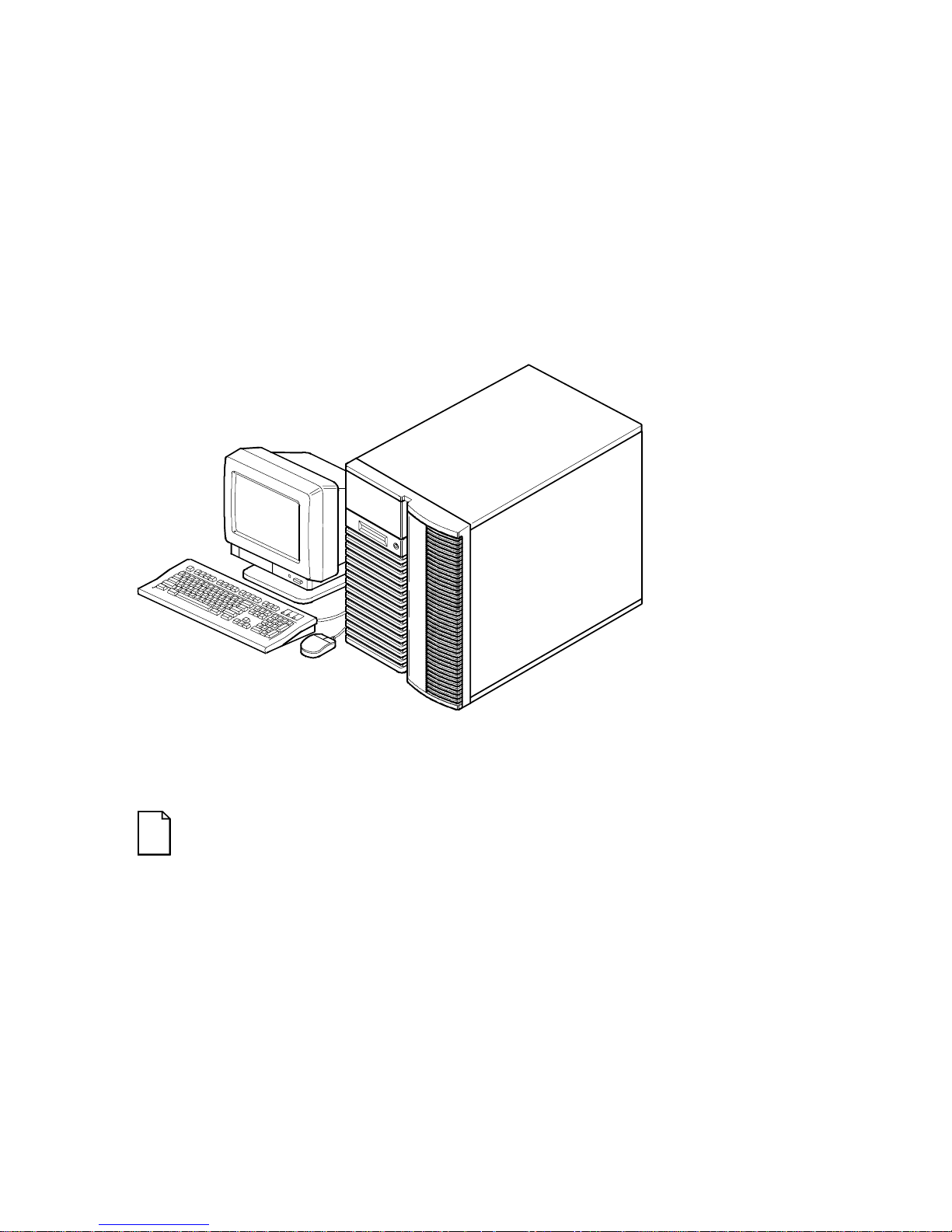
About This Guide
DEC00421
Typical Prioris HX MP Server
NOTE: Your monitor, keyboard, and mouse might look
different.
xiv

Technical Specifications
Introduction
This appendix provides the following technical characteristics for your server:
• Server specifications
• CPU specifications
• EISA expansion slots
• PCI expansion slots
• Power supply and input power requirements
• Current requirements
• Power cord requirements
• Main logic board jumpers
• CPU module jumper settings
A
A-1

Technical Specifications
Server Specifications
The following sections list the server performance, dimensions and
environmental specifications.
Performance Specifications
Attributes Specification
Bus clock
EISA
PCI
Data I/O
EISA
PCI
8.33 MHz
25 MHz
8-bit and 16-bit
32-bit
Memory module
DRAM
System flash ROM
BIOS
VGA flash ROM
BIOS
Server Dimensions
Dimension Specification
Width 371.94 mm (14.6 in.)
Length 589.33 mm (23.2 in.)
Height 513.87 mm (20.23 in.)
Weight 24.5 kg (54.02 lbs)
32 MB minimum. Up to 512 MB parity memory
on each memory module, using 8, 16, or 32 MB
SIMMs.
128 KB
128 KB
A-2

Environmental Specifications
Attributes Specification
Technical Specifications
Operating temperature
Storage temperature
Operating humidity
(noncondensing)
Storage humidity
(noncondensing)
10°C to 40°C (50°F to 104°F)
C to 65°C (−4°F to 149°F)
−20°
20% to 80% relative humidity,
maximum wet bulb 40°C (104°F)
10% to 90% relative humidity,
maximum wet bulb 65°C (149°F)
Altitude
Operating
Nonoperating
2,438 m (8,000 ft) maximum
4,876 m (16,000 ft) maximum
Shipping vibration IAW Federal Standard 101, method 5019
Nonoperating shock 30 G, 25 ms halfsine
A-3

Technical Specifications
CPU Specifications
Your Prioris HX MP server comes with one, two, or four Pentium processor(s)
installed on one or two CPU modules. High-performance caching circuitry and
voltage regulation for each CPU are also located on the CPU module(s).
EISA Expansion Slots
The main logic board contains six EISA expansion slots (one slot is a shared
PCI/EISA slot). These slots support +5 V dc.
PCI Local Bus Expansion Slots
The main logic board contains six PCI local bus expansion slots (one slot is a
shared PCI/EISA slot). These slots support:
5 V dc only PCI expansion boards
•
5/3.3 V dc universal PCI expansion boards
•
Bus mastering
•
Power Supply and Input Power Requirements
The 450 W auto-sensing power supply provides five dc voltages: +12 V dc,
−
12 V dc, +5 V dc, −5 V dc, and 3.3 V dc
various components within the server. The following lists the input power
requirements.
Rated Voltage
Range
100 V ac - 120 V ac 90 V ac - 135 V ac 9.5 A 47 Hz - 63 Hz
220 V ac - 240 V ac 180 V ac - 265 V ac 5 A 47 Hz - 63 Hz
(1)
Includes outlet current
A-4
Maximum Range Rated
.
These voltages are used by the
Operating
Input Current
(1)
Frequency
Range

Current Requirements
Your server family power supply provides the following output ratings:
• +5 V dc 2.5 A min, 52 A max.
• +3.43 V dc 0 A min, 37.4 A max.
• +12 V dc 0.5 A min, 11 A max.
• −12 V dc 0 A min, 0.5 A max.
• −5 V dc 0 A min, 0.2 A max.
+5 V dc and +3.43 V dc maximum total output: 355 W.
+5 V dc and +3.43 V dc and +12 V dc maximum total output: 420 W.
Power supply total output: 450 W maximum.
Technical Specifications
A-5

Technical Specifications
Power Cord Requirements
The power cord used with this server must meet the following criteria:
• UL and CSA Certified cordage rated for use at 250 V ac with a current
rating that is at least 125% of the current rating of the product. In
Europe, the cordage must have the <HAR> mark.
• The ac plug is terminated in a grounding-type male plug designed for
use in the region. It must also have marks showing certification by an
agency acceptable in the region.
• The connector at the server end is an IEC type CEE-22 female
connector.
• The maximum length is 4.5 meters (14.5 feet).
A-6

Main Logic Board Jumpers
The following table lists the main logic board jumpers and factory-default
settings. Figure A-1 shows their locations.
Technical Specifications
CAUTION:
Do not touch any electronic component unless
you are safely grounded. Wear a grounded wrist strap or touch
an exposed metal part of the server chassis. A static discharge
from your fingers can result in permanent damage to electronic
components.
Feature Description Setting
(1)
(1)
(1)
(1)
(1)
(1)
(1)
(1)
(1)
J7, jumpered
J7, open
J9, jumpered
J9, open
J11, jumpered
J11, open
J13, jumpered
J13, open
J14, jumpered
J14, open
J32, jumpered
J32, open
J33, jumpered
J33, open
J38, pins 1 and 2 jumpered
J38, pins 2 and 3 jumpered
J39, jumpered
J39, open
DSM Not install
Install
Doorlock 1
(2)
Enabled
Disabled
Doorlock 2
(2)
Enabled
Disabled
Recovery mode Recovery mode
Normal
Password clear Password clear (MFG test)
Normal mode
Onboard VGA Enabled
Disabled
VGA IRQ 9 Enabled
Disabled
Boot block
(3)
update
Enabled
Disabled
BIOS upgrade Enabled
Disabled
(1)
Factory default setting
(2)
The power switch interlocks are connected when the doorlock jumpers are enabled.
(3)
Disabling this jumper prevents corruption of the BIOS boot block when a boot block update
is not required.
(1)
(1)
(1)
(1)
(1)
(1)
(1)
(1)
(1)
A-7
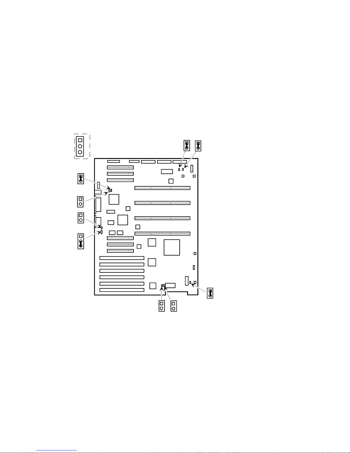
Technical Specifications
J32
J33
J39
J38
1
2
J11
J9
3
J7
Figure A-1. Main Logic Board Jumper Locations
A-8
J14
J13
DEC00578-3

CPU Module Jumper Settings
The following table lists the main logic board jumpers and factory default
settings. Figure A-2 shows its location.
Technical Specifications
CAUTION:
you are safely grounded. Wear a grounded wrist strap or touch
an exposed metal part of the server chassis. A static discharge
from your fingers can result in permanent damage to electronic
components.
Do not touch any electronic component unless
A-9

Technical Specifications
Feature Description Setting
CPU frequency
core/bus ratio
3/2
J3, off
J4, off
J7, off
J8, off
(1)
(1)
(2)
(2)
(1)
2/1
J3, off
J4, on
J7, off
J8, on
3/1
J3, on
J4, off
J7, on
J8, off
5/2
J3, on
J4, on
J7, on
J8, on
APIC Enable
Disable
(1)
For CPU 1
(2)
For CPU 2
(3)
Factory default setting
Digital recommends that you do not change the factory default settings.
J10, on
J10, off
(1)(3)
(1)(3)
(2)
(2)
(1)
(2)
(2)
(2)
(1)
(1)
(2)
(2)
A-10
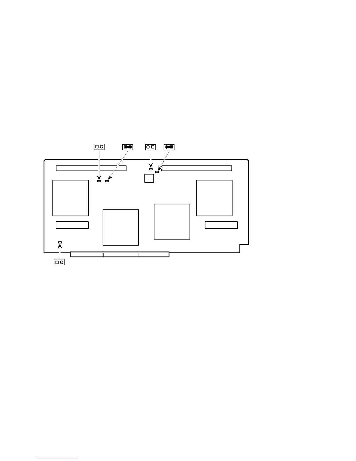
Technical Specifications
J10
J7
J8 J4 J3
Figure A-2. CPU Module Jumper Settings
DEC00583-4
A-11

 Loading...