

Digital Equipment Prioris HX590, Prioris HX590 DP Service Maintenance Manual

MCS
LOGISTICS
ENGINEERING
Service
Maintenance
Manual
PRIORIS HX590
& HX590 DP Server
P
R
I
O
R
I
S
H
X
NIJMEGEN
THE NETHERLANDS
Copyright Digital Equipment Corporation
All rights reserved
November 1995
K-MN-SD00000-02-JG00.A

P
R
I
November 1995
O
R
The information in this document is subject to change without notice and should not be construed as a
commitment by Digital Equipment Corporation.
I
Digital Equipment Corporation assumes no responsibility for any errors that might appear in this document.
S
The software, if any, described in this document is furnished under a license and may be used or copied only in
accordance with the terms of such license. No responsibility is assumed for the use or reliability of software or
equipment that is not supplied by Digital Equipment Corporation or its affiliated companies.
H
Restricted Rights: Use, duplication, or disclosure by the U.S. Government is subject to restrictions as set forth
X
in subparagraph (c) (1) (ii) of the Rights in Technical Data and Computer Software clause at DFARS 252.227-
7013.
Copyright Digital Equipment Corporation
All Rights Reserved
The following are trademarks of Digital Equipment Corporation:
VENTURIS and the Digital logo.
The following are third party trademarks:
MS-DOS and Windows and Windows NT and Windows NT Server are trademarks of Microsoft Corp.
Novell and Netware are trademarks of Novell, Inc.
SCO and Open Desktop are trademarks of The Santa Cruz Operation, Inc.
UNIX is a registered trademark of UNIX System Laboratories, Inc.
All other trademarks and registered trademarks are the property of their respective holders.
Created by:
Printed in Ireland
MCS Logistics Engineering - Nijmegen

Digital PRIORIS HX590 & HX590 DP Server Table of Contents
Table of Contents
PREFACE..............................................................................................................................................................7
P
R
I
O
R
I
S
CHAPTER 1 PRODUCT DESCRIPTION ...................................................................................................... 9
RODUCT INTRODUCTION.......................................................................................................................................9
P
RODUCT MODELS INFORMATION........................................................................................................................10
P
PRIORIS HX 590 Systems ............................................................................................................................. 10
PRIORIS HX590 DP Systems........................................................................................................................11
CHAPTER 2 SERVER UTILITIES & CONFIGURATION.......................................................................13
ERVER UTILITIES.................................................................................................................................................13
S
PHLASH.EXE.................................................................................................................................................13
Before Using PHLASH.EXE...........................................................................................................................13
Creating a Crisis Recovery Diskette................................................................................................................14
Using the Crisis Recovery Diskette.................................................................................................................14
Upgrading The Server's BIOS.........................................................................................................................15
EPP3SMC.EXE...............................................................................................................................................15
ONFIGURING THE SERVER..................................................................................................................................15
C
The SCU .......................................................................................................................................................... 16
Before Using the SCU......................................................................................................................................16
SCI Files and CFG Files..................................................................................................................................17
Using the SCU .................................................................................................................................................17
Configure The Computer.................................................................................................................................18
Adding ISA Boards.......................................................................................................................................... 19
AND SETUP OPTIONS ....................................................................................................................................19
SCU
SCU Main Menu.............................................................................................................................................. 20
Main Menu Options.........................................................................................................................................21
Boot Options....................................................................................................................................................21
Keyboard Features...........................................................................................................................................22
Memory and Cache Options............................................................................................................................22
Security Options .............................................................................................................................................. 23
Integrated Peripherals......................................................................................................................................24
Advanced Chipset Control...............................................................................................................................25
PCI Devices ..................................................................................................................................................... 25
CHAPTER 3 SERVICE PROCEDURES.......................................................................................................27
AFETY REQUIREMENTS.......................................................................................................................................27
S
ECOMMENDED TOOLS........................................................................................................................................28
R
Other Needed Materials...................................................................................................................................28
Required Special Tools.................................................................................................................................... 28
Remedial Diagnostic Test Software................................................................................................................28
ECO/FCO I
EMOVING THE SIDE PANEL.................................................................................................................................29
R
XPANSION SLOTS ................................................................................................................................................32
E
NFORMATION .....................................................................................................................................28
BIOS version information................................................................................................................................28
Server Components (Left Side) ....................................................................................................................... 30
Server Components (Right Side).....................................................................................................................31
H
X
MCS Logistics Engineering - Nijmegen 3

P
Table of Contents Digital PRIORIS HX590 & HX590 DP Server
R
MAIN LOGIC BOARD JUMPERS ............................................................................................................................. 33
I
O
R
I
S
H
X
Main Logic Board Jumper Settings................................................................................................................. 33
Main Logic Board Jumper Locations.............................................................................................................. 34
OMPUTER MEMORY CONFIGURATIONS.............................................................................................................35
C
Memory Configurations .................................................................................................................................. 35
PRIORIS HX590 & HX 590 DP SIMM Locations.......................................................................................37
ART REMOVAL AND REPLACEMENT PROCEDURES...........................................................................................38
P
Removing the 3½-inch Diskette Drive............................................................................................................38
Removing the CD-ROM Drive ....................................................................................................................... 39
Remove the CPU Module................................................................................................................................40
Replacing the CPU Chip..................................................................................................................................41
CPU Module Jumper Settings.........................................................................................................................42
Set the CPU voltage to 3.3V............................................................................................................................42
Remove the Memory Module..........................................................................................................................43
Removing the Main Logic Board....................................................................................................................44
Removing the Power Supply...........................................................................................................................45
Removing the Optional Power Supply............................................................................................................46
Replacing Secondary Cache Memory.............................................................................................................47
Replacing a Device Into the Hot-Swap Drive Bay ......................................................................................... 48
SBB LED Status Indicators............................................................................................................................. 49
Replacing the Server Battery/Real Time Clock (RTC)..................................................................................50
ONNECTING SCSI DEVICES ................................................................................................................................51
C
SCSI Configuration Guidelines....................................................................................................................... 51
External SCSI Bus Guidelines ........................................................................................................................ 51
SCSI Drive IDs................................................................................................................................................52
SCSI ID Settings.............................................................................................................................................. 52
SCSI Jumper Locations..................................................................................................................................52
Using Multiple or Multi-Channel SCSI Host Adapters..................................................................................53
Connecting a Single Channel SCSI Bus ......................................................................................................... 53
Single Channel SCSI Bus - Legend.................................................................................................................54
Connecting a Dual Channel SCSI Bus............................................................................................................55
Dual Channel SCSI Bus - Legend................................................................................................................... 55
External SCSI Bus...........................................................................................................................................56
CHAPTER 4 TROUBLESHOOTING............................................................................................................ 57
NITIAL TROUBLESHOOTING ................................................................................................................................. 57
I
EEP CODES..........................................................................................................................................................58
B
AND BOOT MESSAGES...............................................................................................................................58
POST
ERVER TROUBLESHOOTING................................................................................................................................61
S
ISK DRIVE TROUBLESHOOTING .........................................................................................................................63
D
CD-ROM T
ONITOR TROUBLESHOOTING ............................................................................................................................. 64
M
QAP
ROUBLESHOOTING............................................................................................................................. 64
LUS/FE ADVANCED DIAGNOSTICS ...............................................................................................................65
QAPlus/FE Error Messages............................................................................................................................. 65
4 MCS Logistics Engineering - Nijmegen

Digital PRIORIS HX590 & HX590 DP Server Table of Contents
CHAPTER 5 DEVICE MAPPING..................................................................................................................67
CPU Memory Address Map (Full Range, 590 CPUs)....................................................................................67
CPU Memory Address Map (PC Compatibility Range)................................................................................. 68
CPU I/O Address Map.....................................................................................................................................68
DMA Channel Assignment.............................................................................................................................. 68
I/O Address Map.............................................................................................................................................. 69
PCI Configuration Space Address Map .......................................................................................................... 69
Server Interrupt Levels ....................................................................................................................................69
CHAPTER 6 PASS / FAIL CRITERIA..........................................................................................................71
APPENDIX A SERVICE NOTES....................................................................................................................73
ECOMMENDED TOOLS........................................................................................................................................73
R
Other Needed Materials...................................................................................................................................73
Required Special Tools.................................................................................................................................... 73
Remedial Diagnostic Test Software................................................................................................................73
Recommended Virus Detection and Cleanup Software..................................................................................73
ECO/FCO I
APPENDIX B USEFUL INFORMATION.....................................................................................................75
ELATED DOCUMENTATION .................................................................................................................................75
R
N-LINE BULLETIN BOARDS................................................................................................................................75
O
DOCUMENT FEEDBACK..............................................................................................................................77
PERSONAL NOTES..........................................................................................................................................79
READERS COMMENTS....................................................................................................................................83
NFORMATION.....................................................................................................................................74
BIOS version information................................................................................................................................74
P
R
I
O
R
I
S
H
X
MCS Logistics Engineering - Nijmegen 5

P
Table of Contents Digital PRIORIS HX590 & HX590 DP Server
R
I
O
Table of Figures
R
I
Figure 2 - 1 SCU Main Menu Options................................................................................................................16
S
Figure 2 - 2 SCU Main Menu Options................................................................................................................20
Figure 3 - 1 Unlocking and Removing the Side Panel........................................................................................29
Figure 3 - 2 Server Components (Left Side) ....................................................................................................... 30
H
Figure 3 - 3 Server Components (Right Side).....................................................................................................31
X
Figure 3 - 4 PRIORIS HX Server Expansion Board Slots..................................................................................32
Figure 3 - 5 Main Board Jumper Locations........................................................................................................34
Figure 3 - 6 Memory Module..............................................................................................................................37
Figure 3 - 7 Replacing the 3½-inch Diskette Drive ............................................................................................ 38
Figure 3 - 8 Removing the CD-ROM drive ........................................................................................................ 39
Figure 3 - 9 Removing the CPU module.............................................................................................................40
Figure 3 - 10 Replacing the CPU Chip................................................................................................................41
Figure 3 - 11 Set the CPU Voltage to 3.3 Volt ................................................................................................... 42
Figure 3 - 12 Removing the Memory Module .................................................................................................... 43
Figure 3 - 13 Removing the Main Logic Board..................................................................................................44
Figure 3 - 14 Removing the Power Supply.........................................................................................................45
Figure 3 - 15 Removing the Optional Power Supply..........................................................................................46
Figure 3 - 16 Replacing the Secondary Cache Module.......................................................................................47
Figure 3 - 17 Replacing a Device Into the Hot-Swap Drive Bay ....................................................................... 48
Figure 3 - 18 Replacing the Server Battery/Real Time Clock (RTC)................................................................50
Figure 3 - 19 SCSI Jumper Locations.................................................................................................................52
Figure 3 - 20 Connecting a Single Channel SCSI Bus ....................................................................................... 54
Figure 3 - 21 Connecting a Dual Channel SCSI Bus..........................................................................................55
Figure 3 - 22 Connecting a external SCSI Bus...................................................................................................56
6 MCS Logistics Engineering - Nijmegen

Digital PRIORIS HX590 & HX590 DP Server Preface
Preface
The Digital PRIORIS HX590 & HX590 DP Server Service Maintenance Manual is a troubleshooting guide
that can be used for reference when servicing the PRIORIS HX590 & HX590 DP Server series.
Digital Equipment Corporation reserves the right to make changes to the Digital PRIORIS HX590 & HX590
DP Server without notice. Accordingly, the diagrams and procedures in this document may not apply to the
computer(s) you are servicing since many of the diagnostic tests are designed to test more than one product.
CAUTION
Digital recommends that only A+ certified engineers attempt to repair this equipment.
All troubleshooting and repair procedures are detailed to support subassembly/module
level exchange. Because of the complexity of the individual boards and subassemblies, no
one should attempt to make repairs at component level or to make modifications to any
printed wiring board. Improper repairs can create a safety hazard. Any indications of
component replacement or printed wiring board modifications may void warranty or
exchange allowances.
P
R
I
O
R
I
S
H
X
MCS Logistics Engineering - Nijmegen 7


Digital PRIORIS HX590 & HX590 DP Server Product Description
Chapter 1 Product Description
Product Introduction
The PRIORIS HX590 & HX590 DP Servers are a family of high-performance, highly-scalable network and
application servers featuring the latest in modular CPU and Storage technology. Developed using the state-ofthe-art technology, PRIORIS HX Servers are the most advanced servers in their class.
Description PRIORIS HX590 & HX590 DP Servers, all:
♦ Single and dual 90 MHz Pentium processor with 512 KB onboard writeback cache
♦ 64-bit memory card supporting up to 512 MB parity or 256 MB ECC memory
♦ On board Cirrus 5482 16-bit , 512KB video memory
♦ 6 PCI slots (3 Primary and 3 secondary) and 6 EISA I/O slots
♦ 10 external expansion slots
♦ Redundant cooling (2 fans, 2 spare fans)
♦ Single 450 watt power supply with fan
♦ Optional Redundant Power supply 450 watt
♦ 1 inch double-speed CD-ROM with SCSI interface
♦ 3.5 inch 1.44 Mb floppy disk
♦ Two 5.25 inch half-height disk bays
♦ Integral hot swap bay with 7 drives to support Storageworks Storage
♦ Building Block (SBB) drives
♦ Fast/wide SCSI-2 and narrow RAID configurations
♦ SCSI cabling supports both wide and narrow controllers and devices
♦ Rackmountable
♦ Total connectable storage capacity up to 1000 GB
♦ Six fans with two redunant backup fans
P
R
I
O
R
I
S
H
X
MCS Logistics Engineering - Nijmegen 9

P
Product Description Digital PRIORIS HX590 & HX590 DP Server
R
I
O
Product Models Information
R
There are three different system configurations that are currently offered for both single (PRIORIS HX590) as
I
well as dual (PRIORIS HX590 DP) processor servers:
S
Base Systems are built around 16MB (single processor) or 32MB (dual processor) of parity RAM memory
H
and a Fast Wide (16-bit) SCSI host controller.
X
RAID Systems are built around 16MB (single processor) parity DRAM memory and two 1GB Storage
Building Block (SBBs) with a narrow (8-bit) intelligent EISA SCSI RAID controller or 32MB (dual
processor) of Error Correction Code (ECC) DRAM memory and four 1GB Storage Building Block (SBBs)
with a narrow (8-bit) intelligent EISA SCSI RAID controller.
Kernel Systems contain no SCSI controller and must be ordered with at least 16MB of DRAM memory.
With these systems either wide or narrow, non-RAID or RAID host controllers can be added. Kernel systems
may not be available in all territories.
The tables on the following pages provide details on these configurations:
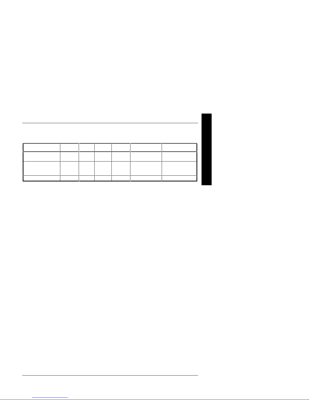
PRIORIS HX 590 Systems
Model Memory Cache FDD HDD Host Contr. CD-ROM
FR−−880WW−−AA
FR−−880WW−−AB
FR−−880WW−−AC
FR−−880WW−−AD
FR−−880WW−−LA
FR−−880WW−−AX
(1)
No memory installed, at least 16MB must be ordered with the system.
16 MB
parity
16 MB
Parity
32MB
ECC
32MB
ECC
32MB
parity
(1)
none 512KB 1.44MB none None SCSI-2, 600 KB/sec
512KB 1.44MB None Adaptec 2940W
512KB 1.44MB 2 x 1.0
GB
SCSI-2
512KB 1.44MB None Adaptec 2940W
512KB 1.44MB 2 x 1GB,
SBB
512KB 1.44MB 1GB
SCSI-2
1 channel, Wide
1 channel,
Narrow RAID,
EISA
1 channel, Wide
1 channel
Narrow RAID,
EISA
Adaptec 2940W
1 channel, Wide
SCSI-2, 600 KB/sec
SCSI-2, 600 KB/sec
SCSI-2, 600 KB/sec
SCSI-2, 600 KB/sec
SCSI-2, 600 KB/sec
10 MCS Logistics Engineering - Nijmegen
Digital PRIORIS HX590 & HX590 DP Server Product Description
PRIORIS HX590 DP Systems
Model Memory Cache FDD HDD Host Contr. CD-ROM
FR−−881WW−−AA
FR−−881WW−−AB
FR−−881WW−−AX
(1)
No memory installed, at least 16MB must be ordered with the system.
32 MB
parity
32 MB
ECC
(1)
None 512KB 1.44MB None None SCSI-2, 600 KB/sec
512KB 1.44MB None Adaptec 2940W
512KB 1.44MB 4 x 1GB,
SCSI-2
1 channel, Wide
1 channel,
Narrow RAID,
EISA
SCSI-2, 600 KB/sec
SCSI-2, 600 KB/sec
P
R
I
O
R
I
S
H
X
MCS Logistics Engineering - Nijmegen 11


Digital PRIORIS HX590 & HX590 DP Server Utilities & Configuration
Chapter 2 Server Utilities & Configuration
Server Utilities
The following sections provide detailed instructions on running the MS-DOS utilities contained on the supplied
CD-ROM startup diskette and CD-ROM. Note that these utilities can also be copied to the hard disk drive.
Refer to the operating system documentation for information on copying files.
PHLASH.EXE
All servers have BIOS software in a read-only, non-volatile memory (ROM) chip. The BIOS initializes
hardware and boots the operating system when the server is turned on. The BIOS also provides access to other
services such as keyboard and disk drive.
The server comes equipped with flash memory. This means that the server's BIOS can be restored simply by
running the PHLASH.EXE utility. You can also upgrade the server's BIOS to future releases by running
PHLASH.EXE along with any flash BIOS update diskette if necessary.
P
R
I
O
R
I
S
H
X
Before Using PHLASH.EXE
When not familiar with utility programs and their uses, carefully read and understand the following instructions
before attempting to use PHLASH.EXE.
Have the following items available:
♦ Blank 3½-inch 1.44 MB formatted diskette.
♦ Diskette copy of the server utilities.
MCS Logistics Engineering - Nijmegen 13

P
Utilities & Configuration Digital PRIORIS HX590 & HX590 DP Server
R
I
O
Creating a Crisis Recovery Diskette
R
A crisis recovery diskette should always be prepared before attempting to upgrade the BIOS. This diskette is
I
used to reprogram the BIOS in case the flash process fails.
S
To create a crisis recovery diskette:
H
1) Turn on the server and allow the POST to complete. If thePOST detects an error and take the appropriate
X
steps to correct the problem. After the problem has been resolved, restart the server.
2) Insert the startup and utilities diskette and make sure the following files are in the UPGRADE directory:
MINIDOS.SYS
PHLASH.EXE
DEVTBLS.DAT
PHLASH.INI
PRIORISHX.ROM
MAKEBOOT.EXE
MAKECRD.EXE
3) Create the same directory on the hard disk drive and then copy the above files to it.
4) Insert a blank formatted diskette into drive A.
5) From drive C: type MAKECRD. This copies the files to drive A.
6) Remove the crisis recovery diskette from drive A and store it in a safe place.
Using the Crisis Recovery Diskette
The crisis recovery diskette must be used only if the server’s BIOS fails or if a BIOS upgrade was unsuccessful
♦ POST detects an error after a normal boot cycle or a BIOS upgrade.
♦ The BIOS in the bootblock memory executes.
♦ The server beeps several times.
♦ The diskette drive begins searching for the crisis recovery diskette.
If the server’s BIOS fails:
1) Turn off the server and set the recovery jumper (J39) to recovery mode.
2) Insert the crisis recovery diskette into drive A and power on the server.
3) After the BIOS is restarted, turn off the power and remove the crisis recovery diskette from drive A.
4) Set the recovery jumper (J39) back to normal to prevent unauthorized personnel from loading a new
5) Turn the power back on for normal operation.
14 MCS Logistics Engineering - Nijmegen
server BIOS.

Digital PRIORIS HX590 & HX590 DP Server Utilities & Configuration
Upgrading The Server's BIOS
Perform the following steps to update the server's BIOS in flash memory:
1) Turn on the server and allow the POST to complete.
If POST detects an error, take the appropriate steps to correct the problem. After the problem has been
resolved, restart the server.
2) Create a crisis recovery diskette. Refer to “Creating a Crisis Recovery Diskette” previously described.
3) Insert the startup and utilities diskette.
4) At the MS-DOS prompt:
change directory to a:\UPGRADE
type: PHLASH /e
A screen appears on the monitor warning that you are about to erase the server’s BIOS.
P
R
I
O
R
I
S
H
X
NOTE If you need to flash a file other than the one on the diskette, copy the new file to the
5) Press [Enter] to continue. If not, press [Esc] to cancel.
Once [Enter] is pressed, PHLASH.EXE automatically updates the server’s BIOS.
6) After the flashing process completes, the server automatically reboots itself so changes immediately take
7) Remove the startup utilities diskette.
upgrade directory and type:
PHLASH [filename]
effect.
EPP3SMC.EXE
EPP3SMC.EXE can be executed as an MS-DOS command or added to the CONFIG.SYS file as a device
driver. In either case, use the BIOS Setup utility or the SCU to set the parallel port to EPP mode.
Configuring The Server
This chapter provides detailed information on how to configure the server using the System Configuration
Utility (SCU). Digital recommends to use the SCU to initially configure the server and each time you add
hardware, remove hardware, or change server settings.
If the server was delivered with factory-installed hardware and software, the server has already been
configured.
MCS Logistics Engineering - Nijmegen 15
P
Utilities & Configuration Digital PRIORIS HX590 & HX590 DP Server
R
I
O
The SCU
R
The SCU enables to setup and configure the server using the menu driven items shown in figure 2-1.
I
Depending on the installed hardware and level of server security required, you might have to access one or
S
more of these items to properly configure the server.
H
X
SCU
When familiar with utility programs and their uses, refer to the appropriate sections in this chapter to setup or
update the server’s configuration. Otherwise, carefully read and understand this chapter before attempting to
modify the server’s configuration settings.
Read any README files contained on the System Configuration Utility diskette for additional information.
In addition, have the following items readily available:
♦ A 1.44 MB formatted diskette.
♦ Configuration (CFG) files supplied with any installed EISA/PCI expansion boards.
Refer to the section, "SCI Files and CFG Files”, later in this chapter for more information about CFG
♦ Kit installation instructions for any installed optional hardware.
16 MCS Logistics Engineering - Nijmegen
Figure 2 - 1 SCU Main Menu OptionsBefore Using the
files.

Digital PRIORIS HX590 & HX590 DP Server Utilities & Configuration
SCI Files and CFG Files
The SCU creates a System Configuration Information (SCI) file each time the serverhas been configured. This
SCI file can be used on any PRIORIS HX590 (DP) Servers that has been equally configured and can serve as
a backup to the EISA configuration stored in NVRAM memory. The SCI file is maintained on the System
Configuration Utility diskette and has a default name of SYSTEM.SCI.
Configuration (CFG) files contain main logic board, EISA, PCI, and ISA expansion board vital characteristics
and the server resources they require for proper operation. When installing additional EISA, PCI, or ISA
expansion boards, make sure to copy the CFG files (and overlays, if applicable) associated with the expansion
boards, to the System Configuration Utility diskette before attempting to configure the server.
Refer to the option documentation for additional information.
Using the SCU
Use the SCU when experiencing problems with the hard disk and reconfiguration of the server is necessary. In
addition, the SCU should be used to modify the configuration after you add or remove hardware, or change
server settings.
If this is the first time using the SCU, it is recommended to follow the procedures in the order given. If this is a
subsequent session, refer to the appropriate sections to update the server configuration.
To run the SCU, perform the following steps:
1) Install any optional hardware, for example disk drives, EISA expansion boards, and so on. Refer to
Chapter 3, "Service Procedures“.
2) Make a backup copy of the supplied System Configuration Utility diskette. Store the original in a secure
place and only use the backup copy when running the SCU. When unable to make a backup copy, use
the original diskette cautiously.
P
R
I
O
R
I
S
H
X
NOTE It is recommended to run the SCU from the floppy disk and not to install the SCU or
3) Insert the backup System Configuration Utility diskette into drive A and then soft boot (reset) the server.
NOTE The SCU contains help pop-up screens for any selected menu item. Press [F1] to
4) Press [Enter] to display the SCU Welcome screen. If no configuration errors appear, the Welcome screen
5) If applicable, select the Learn About Configuring The Computer option to familiarize with
MCS Logistics Engineering - Nijmegen 17
any of its utilities on a hard disk drive. Running the SCU or any of its utilities from a
hard disk drive might cause memory conflicts between the SCU and application
software. This specifically applies to memory managers and Windows applications.
The SCU introductory screen appears.
display a help screen. Press [Esc] to remove a help screen.
displays information about the SCU. Press [Enter] to display the Main menu and proceed to Step 6. If a
configuration error appears, the Welcome screen displays information about the error and tells to
reconfigure the server. Press [Enter] to display the Main menu, select the Configure Computer
option, then select the View and Edit Details option. Make any changes as indicated by the
POST error message, and then select the Exit and Save option to end the SCU session and boot the
server so the changes take effect.
the SCU.

P
Utilities & Configuration Digital PRIORIS HX590 & HX590 DP Server
R
I
6) If applicable, set the current server time and date using the Set Time and Set Date menu
O
R
I
S
H
X
options.
7) Using the Maintain System Configuration Diskette option, copy the CFG files supplied
with any EISA, PCI, or ISA expansion board.
8) Select the Configure Computer option to configure the server.
9) If applicable, select the Maintain System Configuration Diskette option to create,
change, or update SCI or CFG files.
10) To end the SCU session select the Exit From This Utility option.
11) If applicable, install the operating system and any application software.
Refer to the operating system and application software documentation for installation information.
Configure The Computer
When accessing this menu item for the first time, it is recommended to follow the menu items listed below in
the order given. If this is a subsequent session, refer to the appropriate menu item to update the server
configuration.
Step 1: Important EISA Configuration Information
Step 2: Add or remove boards
Step 3: View or edit details
Step 4: Examine required switches
Step 5: Save and Exit
Step 1: Important EISA Configuration Information
This menu item provides basic EISA configuration information and how i t differs from ISA configuration.
These screens are available at any time during the configuration process by pressing [F1] and by selecting
EISA configuration from the help menu.
Step 2: Adding or Removing Boards
This menu item provides a list of boards and options in the configuration. You can add, move, and delete
boards from this list until it shows all the boards and installed options in the server, including the boards not yet
physically installed. The SCU automatically detects any EISA expansion boards installed on the server and
configures the server accordingly. The SCU does not automatically detect ISA expansion boards.
Step 3: View or Edit Details
This menu item allows to examine and change the setting of each function and the resource allocated for those
functions. When editting a function or resource in this step, you might have to change the switch or jumper
setting.
Step 4: Examine Required Switches
This menu item allows to view settings (switches and jumpers) that need to be manually set and software
drivers that need to be installed. These recommendations must be followed exactly, otherwise the server will
not work properly.
Step 5: Save and Exit
This menu item allows to exit the SCU program with or without saving the configuration settings.
18 MCS Logistics Engineering - Nijmegen

Digital PRIORIS HX590 & HX590 DP Server Utilities & Configuration
Adding ISA Boards
Perform the following steps to add ISA boards to the server configuration:
1) Select "Step 2: Adding and Removing Boards", and update the list of boards and options to include any
ISA boards you are going to install in the server.
2) Select "Step 4: Examine Required Switches", to check the required switch and jumper settings of the
ISA boards.
3) Select "Step 5: Save and Exit", to save the configuration and exit the SCU.
Turn off the server and install the ISA boards.
CAUTION
Do not attempt to physically install boards while the server is turned on.
SCU and Setup Options
The tables below list the options that are available in the BIOS Setup utility and in the SCU (View or Edit
details). Use the keyboard function keys to help select options, change values, and display help information.
P
R
I
O
R
I
S
H
X
NOTE The ROM BIOS Setup utility and the SCU contain the same options as those listed in
MCS Logistics Engineering - Nijmegen 19
the option tables below. Digital recommends to use the SCU to configure the server
each time you add hardware, remove hardware, or change server settings.

P
Utilities & Configuration Digital PRIORIS HX590 & HX590 DP Server
R
I
O
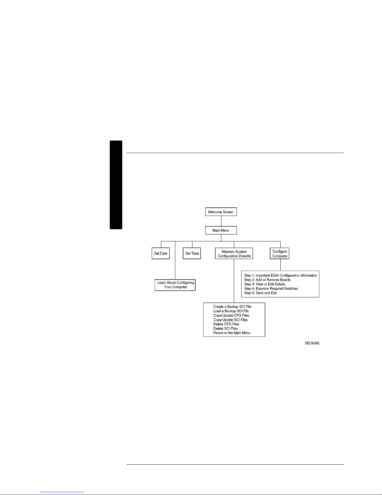
SCU Main Menu
R
The SCU enables to set up and configure the server using a menu-driven interface. Depending on the hardware
I
installed in the server and the level of required server security, you might need to access one or more of the
S
menu items to properly configure the server.
When accessing the SCU, a welcome screen appears, followed by the main menu options listed below. Some
listed menu items access the listed functions directly, while accessing others brings up an appropriate secondary
H
menu.
X
♦ Set Date
♦ Set Time
♦ Learn A.bout Configuring The Computer
♦ Maintain System Configuration
♦ Configure Computer
20 MCS Logistics Engineering - Nijmegen
Figure 2 - 2 SCU Main Menu Options

Digital PRIORIS HX590 & HX590 DP Server Utilities & Configuration
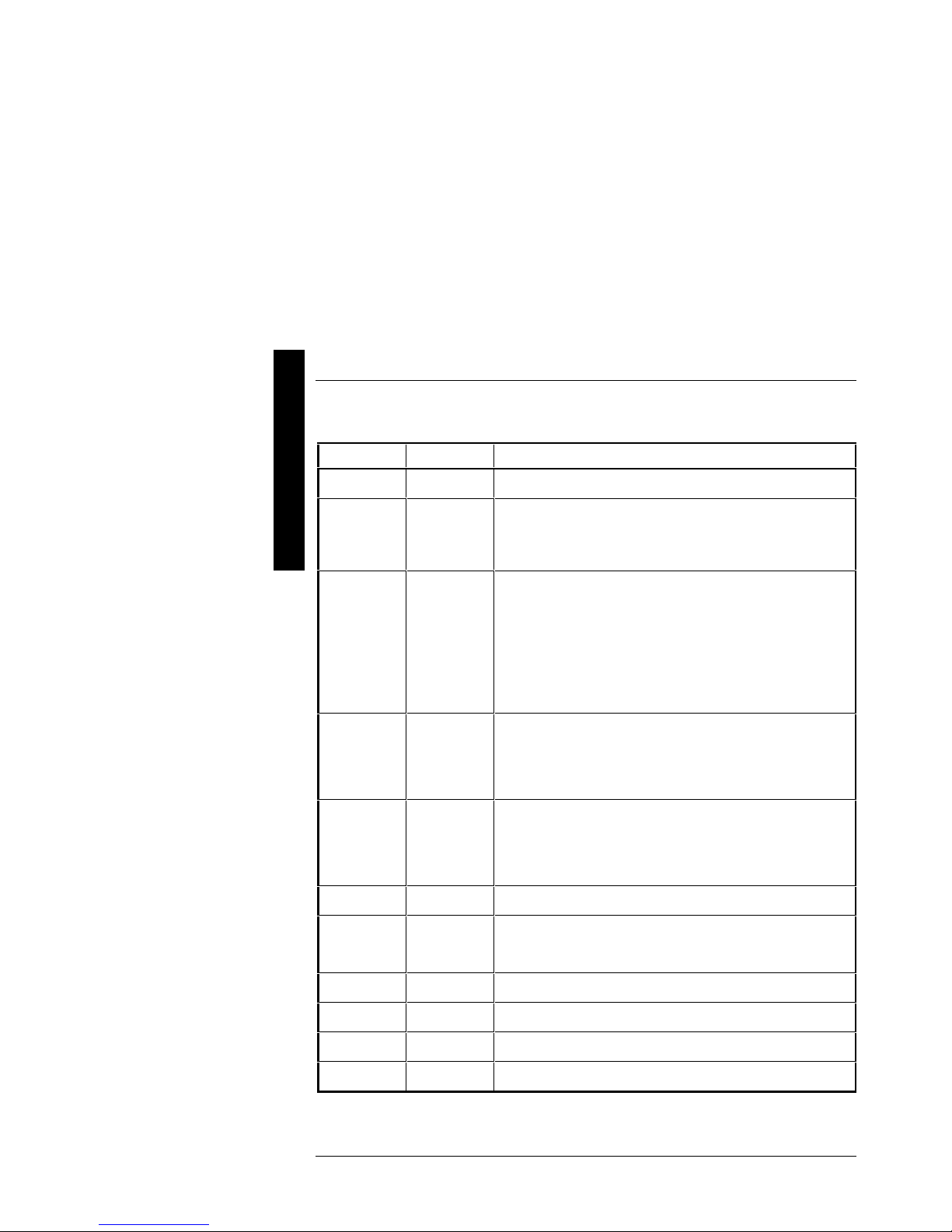
Main Menu Options
Menu Fields Settings Comments
System time
System date
Language
Diskette drive
A Diskette
drive B
IDE Adapter
0/1
Master/Slave
Video system
System
memory
Extended
memory
Current time Displays the current time.
Current date Displays the current date.
English
Español
Français
Deutsch
Italiano
1.44 MB, 3½
2.88 MB, 3½
Not Installed
360 KB, 5¼
1.2 MB, 5¼
720 KB, 3½
Not installed The PRIORIS HX Server family does not support IDE drives.
EGA / VGA
CGA 80x25
Monochrome
Not user
selectable
Not user
selectable
Enables to select a desired language.
Sets the size and density of diskette drives.
Sets the video controller type.
Displays the amount of base (conventional) memory each time the server
boots.
Displays the amount of extended memory each time the server boots.
P
R
I
O
R
I
S
H
X
Boot Options
Menu Fields Settings Comments
Boot option
SETUP
prompt
POST errors
Floppy check
Summary
screen
MCS Logistics Engineering - Nijmegen 21
A: then C:
C: then A:
C: only
Enabled
Disabled
Enabled
Disabled
Enabled
Disabled
Enabled
Disabled
Each time the server boots, it will load the operating system from the
sequence selected.
Enables or disables the <F2> setup prompt each time the server boots.
Enabling this options causes the server to pause and display a setup entry
or resume the boot prompt if an error occurs at boot.
Disabling this option causes the server to always attempt to boot
regardless of a setup entry or error.
Enabling this option causes the server to verify the diskette type each
time the server boots.
Disabling this option speeds up the boot process.
Enabling this option causes the server to display configuration
parameters (in the form of a summary screen) during boot.

P
Utilities & Configuration Digital PRIORIS HX590 & HX590 DP Server
R
I
O
Keyboard Features
R
I
Menu Fields Settings Comments
S
H
X
Keyboard
features
Key click
Keyboard
auto-repeat
rate
Keyboard
auto-repeat
delay
Auto
Off
On
Disabled
Enabled
30/sec
2/sec
6/sec
10/sec
13.3/sec
21.8/sec
26.7/sec
1/2 sec
3/4 sec
1 sec
1/4 sec
Selects the keyboard option.
Enables or disables the audible key click feature.
Sets the number of times a second to repeat a keystroke while holding
the key down.
Sets the delay time after a key is held down before it begins to repeat a
keystroke.
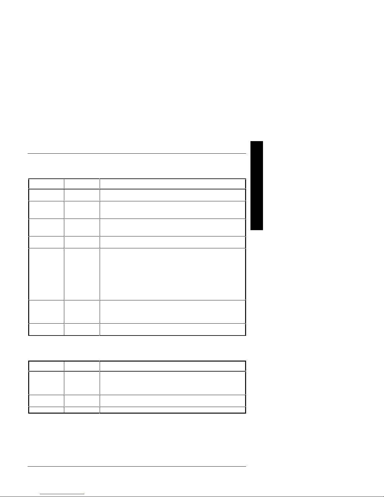
Memory and Cache Options
Menu Fields Settings Comments
Internal cache
External cache
System BIOS
shadow
Cache system
BIOS
Shadow video
BIOS
Cache video
BIOS
Shadow 16K
at: C8000h
CC000h
D0000h
D4000h
D8000h
DC000h
Enabled
Disabled
Enable
Disable
Enabled
Disabled
Enabled
Disabled
Enabled
Disabled
Enabled
Disabled
Enabled
Disabled
Enables or disables the server’s internal cache.
Enables or disables the server’s external cache.
Enables or disables the server’s BIOS shadowing option.
Enables or disables caching control of the system BIOS system area.
Enables or disables the server’s shadow video ROM option.
Enables or disables caching control of the video BIOS area.
Allows to enable or disable shadowing of individual segments of ROM
to increase server performance.
22 MCS Logistics Engineering - Nijmegen

Digital PRIORIS HX590 & HX590 DP Server Utilities & Configuration
Memory and Cache Options (continued)
Menu Fields Settings Comments
AT bus space
Disabled
F00000h, 1 MB
E00000h, 2 MB
C00000h,
4 MB
Memory hole not available upper memory is contiguous.
Sets the memory hole at address F00000 with 1 MB memory available.
Sets the memory hole at address E00000 with 2 MB memory available.
Sets the memory hole at address C00000 with 4 MB memory available.
Security Options
Menu Fields Settings Comments
Supervisor
password is
User password
is
Set supervisor
password
Set user
password
Password on
boot
Diskette access
Fixed disk
boot sector
Network
server
System backup
reminder
Virus check
reminder
Not user
selectable
Not user
selectable
Press [Enter] Enables to set a supervisor password.
Press [Enter] Enables to set a user password.
Enabled
Disabled
Supervisor
User
Normal
Write protect
Disabled
Enabled
Disabled
Daily
Weekly
Monthly
Disabled
Daily
Weekly
Monthly
Tells whether or not the supervisor’s password is enabled or disabled.
Tells whether or not the user’s password is enabled or disabled.
Enables or disables the enter password on boot option.
Enables to control who has access to diskette drives.
Enables to write protect the boot sector on the hard disk drive.
This option keeps the server from being accessed during network
operation.
Enables or disables the system backup reminder message.
Enables or disables the virus check reminder message.
P
R
I
O
R
I
S
H
X
MCS Logistics Engineering - Nijmegen 23
P
Utilities & Configuration Digital PRIORIS HX590 & HX590 DP Server
R
I
O
Integrated Peripherals
R
I
Menu Fields Settings Comments
S
H
X
Mouse port
Parallel port
Parallel port
mode
Disabled
Enabled
378, IRQ7
278, IRQ5
Auto
Disabled
3BC, IRQ7
EPP 1.7
EPP 1.9
Enables or disables the mouse port.
Enables or disables the onboard port at the specified address.
Sets the enhanced parallel port mode.
Sets the extended capabilities port mode.
Serial port 1
Serial port 2
Diskette
controller
OCP saver
timer
OCP backlight
Exchange
diskette drives
Diskette write
protection
IDE controller
ECP
Compatible
mode
Bi-directional
mode
Auto
Disabled
3F8, IRQ4
2F8, IRQ3
3E8, IRQ4
2E8, IRQ3
Auto
Disabled
3F8, IRQ4
2F8, IRQ3
3E8, IRQ4
2E8, IRQ3
Enabled
Disabled
5 minutes
15 minutes
30 minutes
Disabled
On
Off
Disabled
Enabled
Disabled
Enabled
Enabled
Disabled
Compatible mode - standard printer connection.
Bi-directional mode - PS/2 compatible mode and able to receive data.
Enables or disables onboard serial port 1 at the specified address.
Enables or disables onboard serial port 2 at the specified address.
Enables or disables the onboard diskette controller.
Selects disabling or a timer value.
If the keyboard and mouse remain inactive for the specified time, the
OCP will be set to an OFF state to increase the life of the OCP.
Selects the power-on state of the OCP backlight.
Enables to logically exchange physical diskette drive designations.
Enables or disables the selected diskette drive’s write protect option.
The server does not support an onboard IDE controller.
24 MCS Logistics Engineering - Nijmegen
Digital PRIORIS HX590 & HX590 DP Server Utilities & Configuration
Advanced Chipset Control
Menu Fields Settings Comments
CPU to PCI
posting
PCI to
memory
posting
CPU to
memory
posting
PCI burst
write
PCI arbiter
Latency timer
value
EISA to PCI
line buffer
Disabled
Enabled
Enabled
Disabled
Enabled
Disabled
Enabled
Disabled
System default
Pure rotating
EISA slots
PCI slots 4-6
CPU
PCI slot 1
PCI slot 2
PCI slot 3
20
90
A0
F0
Enabled
Disabled
Enables or disables the CPU to PCI write buffers. When enabled, these
buffers temporarily store data between writes.
Enables or disables the PCI to DRAM write buffers. When enabled,
these buffers temporarily store data between writes.
Enables or disables the CPU to DRAM write buffers. When enabled,
these buffers temporarily store data between writes.
Enables or disables PCI memory burst write cycles.
Selects the PCI arbiter priority scheme. Select “System Default” for
optimal setting.
Select “Pure Rotating” or a device with the highest priority, if
absolutely needed.
Sets the maximum number of PCI bus clocks that the PMPC can burst as
a master.
Enables or disables the EISA to PCI line buffer.
P
R
I
O
R
I
S
H
X
PCI Devices
Menu Fields Settings Comments
PCI devices,
slot 1/2/3/4/5/6
INTA, INTD,
INTB, INTC
Default latency
timer
Latency
MCS Logistics Engineering - Nijmegen 25
None
IRQ
Enabled
Disabled
0040h Sets the device latency timer.
Selects IRQ routing.
When enabled, the device’s power up latency timer is used.
 Loading...