

Digital Equipment PRIORIS HX User Manual
PRIORIS HX SERVER
USER’S GUIDE

Prioris HX Server
User's Guide
Part Number: ER-881WW-UA. A01
Digital Equipment Corporation

November 1995
The information in this document is subject to change without notice and
should not be construed as a commitment by Digital Equipment
Corporation.
Digital Equipment Corporation assumes no responsibility for any errors
that might appear in this document.
The software, if any, described in this document is furnished under a
license and may be used or copied only in accordance with the terms of
such license. No responsibility is assumed for the use or reliability of
software or equipment that is not supplied by Digital Equipment
Corporation or its affiliated companies.
Restricted Rights: Use, duplication, or disclosure by the U.S. Government
is subject to restrictions as set forth in subparagraph (c) (1) (ii) of the
Rights in Technical Data and Computer Software clause at DFARS
252.227-7013.
Prioris HX Server User's Guide
Copyright Digital Equipment Corporation.
All Rights Reserved.
DEC, Prioris, ServerWORKS, and the Digital logo are trademarks of Digital
Equipment Corporation.
Banyan and VINES are registered trademarks of Banyan System Inc.
Intel, OverDrive, and Pentium are registered trademarks of Intel Corporation.
Logitech is a trademark of LOGITECH, Inc.
Microsoft, MS-DOS, MS OS/2, and Windows for Workgroups are registered
trademarks of Microsoft Corporation.
NeXT is a registered trademark of NeXT, Inc.
Novell and NetWare are U.S. registered trademarks of Novell Inc.
OS/2 and PS/2 are registered trademarks of International Business Machines
Corporation.
PhoenixBIOS is a trademark of Phoenix Technologies Ltd.
SCO Unix is a trademark of The Santa Cruz Operation, Inc.
SCSI
Select
is a registered trademark of Adaptec Corporation.
SIMM is a registered trademark of Wang Laboratories.
All other trademarks and registered trademarks are the property of their
respective holders.

FCC ID: A09-88XWW
The FCC wants you to know...
This equipment has been tested and found to comply with the limits for a
Class B digital device, pursuant to Part 15 of the FCC rules. These limits
are designed to provide reasonable protection against harmful
interference in a residential installation.
Any changes or modifications made to this equipment may void the user's
authority to operate this equipment.
This equipment generates, uses, and can radiate radio frequency energy
and, if not installed and used in accordance with the instructions, may
cause harmful interference to radio communications. However, there is no
guarantee that interference will not occur in a particular installation. If this
equipment does cause harmful interference to radio or television
reception, which can be determined by turning the equipment off and on,
the user is encouraged to try to correct the interference by one or more of
the following measures:
• Reorient or relocate the receiving antenna
• Increase the separation between the equipment and receiver
• Connect the equipment into an outlet on a circuit different from that
to which the receiver is connected
• Consult the dealer or an experienced radio/TV technician for help
The user may find the following booklet prepared by the Federal
Communications Commission helpful:
How to Identify and Resolve Radio-
TV Interference Problems.
This booklet is available from the U.S.
Government Printing Office, Washington, D.C., 20402. Stock No. 00400398-5.
All external cables connecting to this basic unit need to be shielded. For
cables connecting to option boards, see the option manual or installation
instructions.
This digital apparatus does not exceed the Class B limits for radio noise
emissions set out in the radio interference regulations of the Canadian
Department of Communications.

This equipment is in the 2nd Class category (information equipment to be
used in a residential area or an adjacent area thereto) and conforms to the
standards set by the Voluntary Control Council For Interference by Data
Processing Equipment and Electronic Office Machines aimed at
preventing radio interference in such residential area.
When used near a radio or TV receiver, it may become the cause of radio
interference.
Read the instructions for correct handling.
This equipment meets or exceeds requirements for safety in the U.S. (UL
1950), Canada (CSA C22.2 No. 950), and Europe (EN 60950/IEC 950)
with Nordic requirements.
This equipment meets or exceeds the ergonomic requirements of ZH1/618
and is certified to bear the GS mark by TUV Rheinland of Germany.
This equipment has been tested for radio frequency emissions and has
been verified to meet VDE 0871 Class B.

i
Contents
About This Guide
Introduction.......................................................................................... vii
Audience.............................................................................................. vii
Organization......................................................................................... viii
Conventions......................................................................................... ix
Abbreviations ....................................................................................... x
Special Notices .................................................................................... xii
Related Documentation........................................................................ xiii
1
Introduction
Server Software and Support Documentation....................................... 1-3
Diagnostic Software ............................................................................. 1-4
Server Utilities and Technical Support.................................................. 1-4
Restarting Your Server......................................................................... 1-5
Important Information........................................................................... 1-5
Identifying Model and Serial Numbers .................................................. 1-9
Getting Help......................................................................................... 1-10
2
Server Utilities
Introduction.......................................................................................... 2-1
SCSI
Select
Utility................................................................................. 2-2
RAID Configuration Utility..................................................................... 2-2
Flash Utility .......................................................................................... 2-3
Using EPP3SMC.EXE.......................................................................... 2-4

Contents
ii
System Configuration Utility (SCU)....................................................... 2-5
Configuring Expansion Boards.......................................................... 2-5
Locating the SCU............................................................................. 2-6
When to Run the SCU...................................................................... 2-7
SCU Keyboard Function Keys .......................................................... 2-7
Starting and Using the SCU.............................................................. 2-8
Configure Your Computer................................................................. 2-9
Adding ISA Expansion Boards...................................................... 2-10
Adding EISA Expansion Boards.................................................... 2-11
Adding PCI Expansion Boards...................................................... 2-12
Relocating Expansion Boards....................................................... 2-14
Setting the Date and Time................................................................ 2-15
Maintain the SCU Diskette................................................................ 2-16
SCU Options.................................................................................... 2-17
System......................................................................................... 2-18
Diskette Drive Group .................................................................... 2-18
Hard Disk Group........................................................................... 2-19
Boot Options Group...................................................................... 2-19
Keyboard Features Group............................................................. 2-20
Serial Port Group.......................................................................... 2-20
Parallel Port Group....................................................................... 2-21
Video Options Group .................................................................... 2-21
Shadow Options Group................................................................. 2-22
Security Options Group................................................................. 2-23
Cache Options Group................................................................... 2-24
Reserved System......................................................................... 2-24
Miscellaneous............................................................................... 2-25
PCI Slot Options Group: (PCI Slots 1-6) ....................................... 2-26
VGA Graphics Controller .............................................................. 2-26
3
Expanding Your Server
Introduction.......................................................................................... 3-1
Tools Needed....................................................................................... 3-1
Static Electricity.................................................................................... 3-2
Disconnect External Devices and Power............................................... 3-2
Removing the Side Panels ................................................................... 3-2
Server Components (Left Side) ............................................................ 3-4

Contents
iii
Server Components (Right Side).......................................................... 3-6
Main Logic Board Components............................................................. 3-8
Remove the CPU Module..................................................................... 3-10
Remove the Memory Module................................................................ 3-12
Installing Additional Server Memory...................................................... 3-14
Memory Configurations..................................................................... 3-16
Installing a SIMM.................................................................................. 3-17
Replacing the Battery/Real Time Clock (RTC)...................................... 3-20
Installing Expansion Boards.................................................................. 3-22
Adding Mass Storage Devices.............................................................. 3-26
SCSI Configuration Guidelines ............................................................. 3-27
SCSI Cables..................................................................................... 3-28
Installing a Half-Height 5¼-Inch Device into the Top-Right Drive Bay 3-28
Installing a Full-Height 5¼-Inch Device into the Top-Right Drive Bay 3-30
Expansion Brackets...................................................................... 3-32
Installing or Replacing a Device Into the Hot-Swap Drive Bay.......... 3-34
SBB LED Status Indicators........................................................... 3-36
Connecting SCSI Devices .................................................................... 3-37
Storage Backplane........................................................................... 3-37
SCSI Drive IDs................................................................................. 3-39
Single Channel SCSI Configuration .................................................. 3-41
Two Channel SCSI Configuration ..................................................... 3-44
Three Channel SCSI Configuration................................................... 3-46
Using Multiple or Multi-Channel SCSI Host Adapters........................ 3-48
External SCSI Bus............................................................................ 3-49
Connecting an External SCSI Storage Box........................................... 3-51
External SCSI Bus Guidelines.............................................................. 3-51
Installing an Optional Power Supply...................................................... 3-53
Installing the Side Covers..................................................................... 3-55
4
Problem Solving and Troubleshooting
Introduction.......................................................................................... 4-1
Initial Troubleshooting .......................................................................... 4-2
Server Troubleshooting ........................................................................ 4-3
Disk Drive Troubleshooting................................................................... 4-7
Monitor Troubleshooting....................................................................... 4-11
CD-ROM Troubleshooting.................................................................... 4-13

Contents
iv
5
Server Security Features
Introduction.......................................................................................... 5-1
Left and Right Door Security Lock........................................................ 5-2
Left and Right Side Panel Lock............................................................. 5-3
Supervisor Password............................................................................ 5-4
If You Forget Your Password................................................................ 5-5
Additional Security Features................................................................. 5-6
A
Technical Specifications
Introduction.......................................................................................... A-1
CPU Specifications............................................................................... A-1
Server Specifications............................................................................ A-2
Performance Specifications.............................................................. A-2
Server Dimensions........................................................................... A-2
Environmental Specifications............................................................ A-3
EISA Expansion Slots .......................................................................... A-3
PCI Local Bus Expansion Slots ............................................................ A-4
Power Supply and Input Power Requirements...................................... A-4
Current Requirements.......................................................................... A-5
Power Cord Requirements ................................................................... A-6
Main Logic Board Jumpers................................................................... A-6
Main Logic Board Jumper Settings ................................................... A-7
B
Server Messages
Introduction.......................................................................................... B-1
POST Messages.................................................................................. B-1
POST and Boot Messages............................................................... B-2
OCP Messages................................................................................ B-5
Beep Codes ......................................................................................... B-7

Contents
v
C
Caring For Your Server
Introduction.......................................................................................... C-1
Cleaning the Server.............................................................................. C-1
Cleaning the Screen............................................................................. C-1
Cleaning the Mouse.............................................................................. C-2
Moving the Server................................................................................ C-2
Packing the Server........................................................................... C-3
Installing the Server at a New Location............................................. C-3
Figures
Typical Prioris HX Server ........................................................... xiv
1-1. Providing a Comfortable Working Environment........................... 1-8
2-1. SCU Main Menu Options............................................................ 2-8
3-1. Unlocking and Removing the Side Panels................................... 3-3
3-2. Server Components (Left Side) .................................................. 3-5
3-3. Server Components (Right Side)................................................ 3-7
3-4. Main Logic Board Components................................................... 3-9
3-5. CPU Module Removal................................................................ 3-11
3-6. Memory Module Removal........................................................... 3-13
3-7. SIMM Socket Locations and Bank Designations......................... 3-15
3-8. Installing a SIMM........................................................................ 3-19
3-9. Replacing the Battery................................................................. 3-21
3-10. Prioris HX Server Expansion Board Slots .................................... 3-23
3-11. Removing a Metal Filler Plate..................................................... 3-24
3-12. Installing an Expansion Board..................................................... 3-25
3-13. Installing a Half-Height 5¼-Inch Device Into Top-Right Drive Bay 3-29
3-14. Installing a Full-Height 5¼-Inch Device Into Top-Right Drive Bay 3-31
3-15. Installing Expansion Brackets..................................................... 3-33
3-16. Installing a Device Into the Hot-Swap Drive Bay ......................... 3-35
3-17. Storage Backplane..................................................................... 3-38

Contents
vi
3-18. Single Channel SCSI Configuration ............................................ 3-43
3-19. Two Channel SCSI Configuration ............................................... 3-45
3-20. Three Channel SCSI Configuration............................................. 3-47
3-21. External SCSI Bus Connections................................................. 3-50
3-22. Connecting an External SCSI Storage Box................................. 3-52
3-23. Installing an Optional Power Supply............................................ 3-54
3-24. Installing Side Covers................................................................. 3-55
5-1. Front Panel Security Doors Lock................................................ 5-2
5-2. Left and Right Side Panel Lock................................................... 5-3
A-1. Main Logic Board Jumper Locations............................................ A-9

vii
About This Guide
Introduction
This guide describes how to operate, upgrade, configure, and
troubleshoot your Prioris HX Server family. This guide will also help to
familiarize you with all aspects of the server and provide a reference tool
for questions you might have in the future.
If you are initially setting up your server, refer to the Installation Guide and
the ServerWORKS Quick Launch program (supplied on a CD-ROM disk).
The Installation Guide identifies all the components that were shipped
from the factory as well as how to connect the mouse, keyboard, monitor,
and ac power. The Installation Guide also shows how to turn your server
on for the first time and access the ServerWORKS Quick Launch program.
You must run the ServerWORKS Quick Launch program to initially
configure your server, create utility and device driver diskettes, and install
an operating system.
For more information, refer to the ServerWORKS Quick Launch Reference
Guide.
Audience
This guide is written specifically for anyone responsible for operating,
configuring, and expanding the Prioris HX Server family.

About This Guide
viii
Organization
This guide contains the following:
• Chapter 1:
Introduction
—This chapter provides general information
about your server. For example: server software and support
documentation, diagnostic software, server utilities and technical
support, restarting your server, providing a comfortable working
environment, identifying server model and serial numbers, and
learning where to obtain help.
• Chapter 2:
Server Utilities
— This chapter describes the server utilities
that are supplied on the ServerWORKS Quick Launch CD-ROM disk.
• Chapter 3:
Expanding Your Server
—This chapter explains how to
unlock and remove the side panels, install or replace main logic board
options, install CPU modules, install memory modules, and mass
storage devices.
Also, refer to your SCSI, RAID, and other options documentation.
• Chapter 4:
Problem Solving and Troubleshooting
—This chapter
describes initial and advanced troubleshooting solutions.
• Chapter 5:
Server Security Features
—This chapter describes the
various security features that are available to prevent server or data
theft.
• Appendix A:
Technical Specifications
—This appendix lists vital server
operating specifications and main logic board jumper information.
Refer to the User Documentation in Quick Launch for CPU module
information.
• Appendix B:
Server Messages
—This appendix describes the poweron self test (POST) and run-time error messages, including
recommended corrective actions.
• Appendix C:
Caring For Your Server
—This appendix provides
suggestions for cleaning and moving your server.

About This Guide
ix
Conventions
Convention
Example
Description
kp
An italicized word or phrase represents text or
commands you must enter.
c:\windows>
Monospaced text indicates information that your server
or software displays. For example, a directory path or
error message.
[Enter] Square brackets surrounding text represents a keyboard
key.
[Ctrl]+[Alt]+[Del] A plus sign indicates that the keys shown should be
pressed at the same time.
1 234 567 Spaces are used in large numbers instead of commas.

About This Guide
x
Abbreviations
Abbreviation Meaning
BIOS Basic input/output system
CPU Central processing unit
DMA Direct memory access
DRAM Dynamic random access memory
ECC Error correction code
ECP Extended capabilities port
EISA Extended industry standard architecture
EPP Enhanced parallel port
FRU Field replaceable unit
IDE Integrated drive electronics
h An h suffix to a numerical value denotes hexadecimal
numbers. For example, 0F8h equals 0F8 hexadecimal.
I/O Input/output
ISA Industry standard architecture
MS-DOS
Microsoft Disk Operating System
PCI Peripheral component interconnect
POST Power-on self test
RAID Redundant array of independent devices
RAM Random access memory
ROM Read only memory
continued

About This Guide
xi
Abbreviation Meaning
RTC Real-time clock
SBB Storage building block
SCSI Small computer system interface
SCU System Configuration Utility
SIMM Single in-line memory module
VGA Video graphics array
Windows Microsoft Windows application software
ZIF Zero insertion force
About This Guide
xii
Special Notices
Three kinds of special notices are used in this guide to emphasize specific
information.
WARNING: indicates the presence of a hazard that can
cause personal injury if the hazard is not avoided.
CAUTION: indicates the presence of a hazard that
might cause damage to hardware or that might corrupt
software.
NOTES: are used to provide additional information.

About This Guide
xiii
Related Documentation
An
Installation Guide
is available as a supplement to the information
provided in this user's guide. Use the Installation Guide to install and
configure your server.
A ServerWORKS
Quick Launch
program comes with your server on a CDROM disk. This easy-to-use program enables you to install one of several
supported operating systems and provides a single source for all server
documentation, technical support information, diagnostics, and other
related product information.
README files come with your ServerWORKS Quick Launch CD-ROM
disk or as printed material. This README information can help you setup,
configure, and operate your server. Digital recommends that you read this
information first.
SCSI, RAID, diagnostics, and other options manuals are also available.
About This Guide
xiv
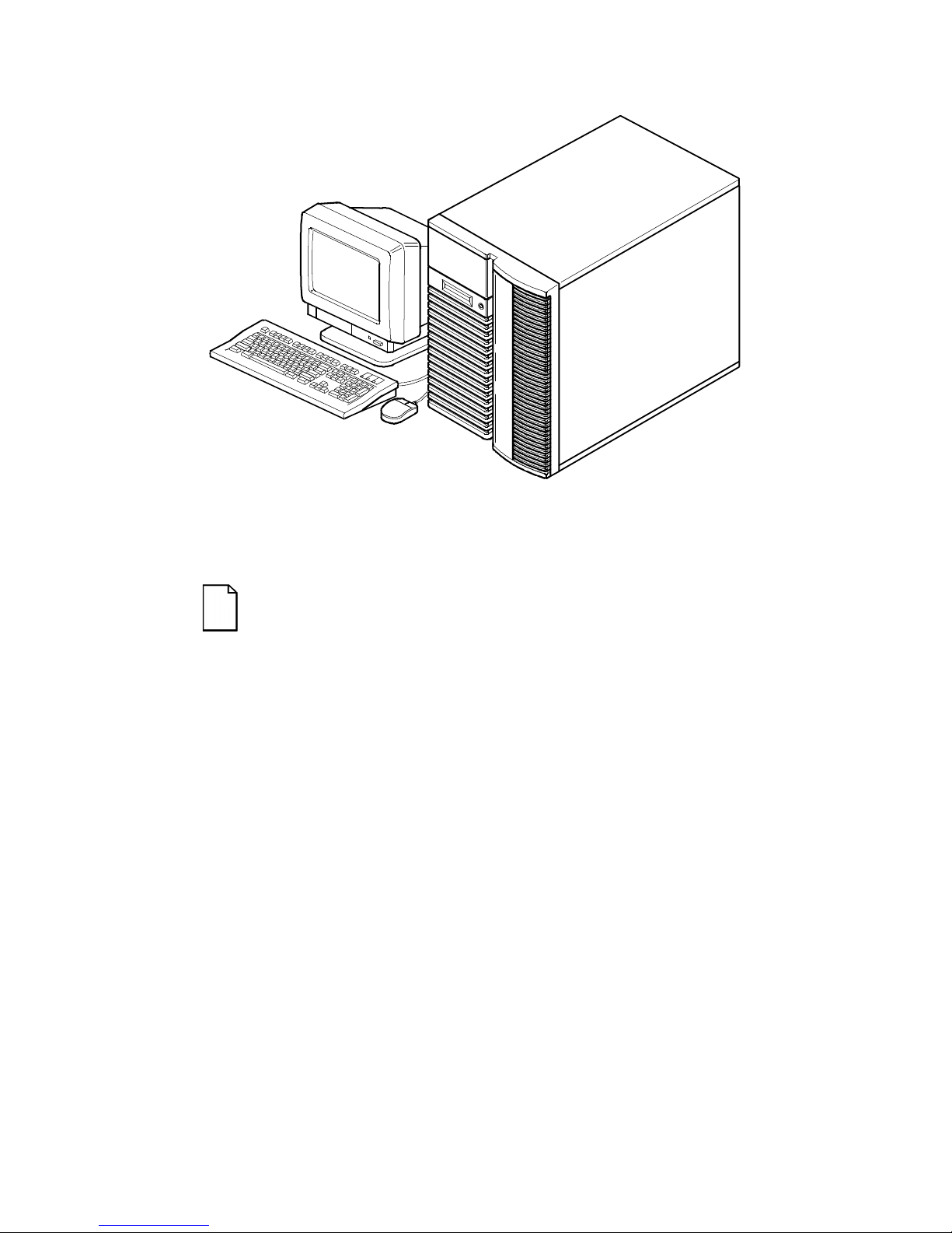
DEC00421
Typical Prioris HX Server
NOTE: Your monitor, keyboard, and mouse might look
different.

1-1
1
Introduction
The Prioris HX Server family is a family of high-performance, highlyscaleable network and application servers featuring the latest in modular
CPU and storage technology. Developed using the following state-of-theart technology, the Prioris HX Servers are the most advanced servers in
their class.
CPU Module
Single (1P) or dual (DP) Intel Pentium processor
mode capable. Both operate using a 64-bit
memory interface and a standard single 256 KB
external cache. All modes support a 32-bit PCI
interface.
Memory Module
One memory module supports two SIMM types.
64-bit parity configuration with eight SIMM sockets
capable of supporting 16 MB to 512 MB of parity
memory or 32 MB to 256 MB of ECC memory.
PCI Fast/Wide
SCSI-2 Adaptec
2940W Controller
A single-channel PCI Fast Wide SCSI-2 adapter
board occupies a single PCI option slot in all
servers. Two channel wide and narrow SCSI-2
adapter boards are available as options.
Integrated Device
Array Storage
Bay
Supports up to seven 3½-inch, wide or narrow
SCSI, hot-swap devices for configuring a mass
storage array using Storage Building Blocks
(SBBs).

Introduction
1-2
RAID Controllers
RAID ready servers enable you to manage data
distribution using multiple disk drives and
specialized array controllers.
Expansion Slots
Six EISA and six PCI slots with bridge support for
a total of 12 slots for maximum expandability.
Redundant Fans
and Power
Supply
For added reliability, your server has redundant
fans for cooling and the option to add a second
power supply.
Operator Control
Panel (OCP)
Back-lit, 16-character LCD display that shows
power-on status messages each time your server
boots. The operator control panel can be lit by
pressing a manual switch on the front bezel.
ServerWORKS
Quick Launch
Enables you to install your operating system and
configure your server from a single CD-ROM disk
application.
ServerWORKS
Manager
Enables a network administrator to monitor critical
PC server statistics and vital CPU component
information necessary to maintain a healthy
network.
The remainder of this chapter provides additional information about your
server’s supplied software and support documentation, restarting your
server, identifying server model and serial numbers, providing a
comfortable working environment, and obtaining help.
NOTE: You might have ordered additional options such as
hard disk drives, tape back-up systems, CD-ROMs, or
modems that have been factory installed in your server. The
documentation and any related diskettes for these options
have also been provided. Save this material for future
reference.

Introduction
1-3
Server Software and Support Documentation
The following software and support documentation is supplied with your
server:
• ServerWORKS software kit contains ServerWORKS Quick
Launch and ServerWORKS Manager.
− ServerWORKS Quick Launch contains a bootable CD-ROM
disk and reference guide. The Quick Launch program steps
you through the initial server setup and operating system
installation process.
− ServerWORKS Manager contains the software and
documentation for installing the ServerWORKS Manager
LAN management tool.
Refer to the Installation Guide and the README files on the ServerWORKS
Quick Launch CD-ROM disk for more information.
• Server documentation box contains this User’s Guide, an
Installation Guide, a Documentation Overview, Warranty
information, a Diagnostics manual, Options manuals, and
Registration Card.

Introduction
1-4
Diagnostic Software
Diagnostic software and support documentation came with your server.
This software contains an advanced set of diagnostic utilities that can be
used to identify and correct problems you might encounter when installing,
configuring, or using your server. There are two ways to access the
supplied diagnostic software:
1. During your operating system installation process, the diagnostic
software is automatically copied to a subdirectory on the MS-DOS
partition. This enables you to run the diagnostic software anytime
from the MS-DOS partition you created.
2. Using the Install Software Conventional method in ServerWORKS
Quick Launch, you can create a bootable diagnostic software
diskette. This enables you to run the diagnostic software anytime
using the diskette you created.
For additional information, read any README files that are on the diagnostic
diskette you created.
Server Utilities and Technical Support
The most current server utilities and technical support information is
available on the Quick Launch CD-ROM disk and the Digital Bulletin
Board Service (BBS). For access to the Digital BBS in the USA, dial
(508) 496-8800.
If you need additional information, access “Service Information” in the
ServerWORKS Quick Launch program that came on your CD-ROM disk.

Introduction
1-5
Restarting Your Server
Method How to Invoke Action Performed
Hard boot Turn the server off, then on, by
pressing the power On/Off
button at the front of the server.
Runs memory tests and clears
all terminate stay resident
programs (TSRs) and memory
registers.
Soft boot Press [Ctrl]+[Alt]+[Del]. Does not run memory tests but
clears all terminate stay
resident programs (TSRs) and
memory registers (operating
system specific).
Reset Press the Reset button at the
front of the server.
Same as a hard boot.
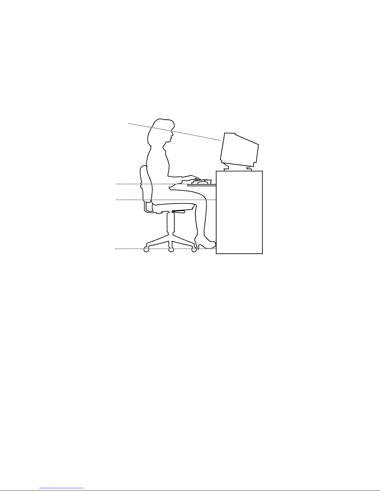
Important Information
Under circumstances of poor posture or poor setup, certain recent
scientific articles suggest that injuries may occur. Other articles suggest
that there is no cause and effect. Because the safety of our users is a
great concern, it is important to take these precautions:
• Be comfortable in your work space.
• Change your posture frequently.
• Proceed according to the recommendations in the following table
and figure.

Introduction
1-6
Adjust So . . .
Chair Feet are flat on the floor.
Legs are vertical forming a right angle to the floor.
Your weight is off your thighs and they are horizontal.
Keep the back of your knees away from the seat so
you do not compress the area behind them, which
could restrict the blood flow.
Your upper body is erect and your lower back is
supported with a backrest.
Keyboard or mouse Your wrists are straight and do not bend more than 15
degrees. They may be supported when resting but not
on sharp edges. Type comfortably, with no more key
pressure than needed to feel the contact point.
Upper arms are straight down at your sides, elbows are
close to your sides and support your arm weight.
Forearms are at a 70 degree to 90 degree angle.
If you use a mouse, rest your hand on the mouse so
your wrist is not on the work surface. Operate the
mouse close to your body’s centerline.
continued

Introduction
1-7
Adjust So . . .
Head Avoid neck strain. Your head should incline downward,
but no more than 15 to 20 degrees.
Monitor No higher than the level of your eyes and at the correct
distance for your vision.
Avoid eye fatigue, which can be caused by glare,
image quality, uncomfortable furniture, eye height, and
uncorrected vision. If you cannot focus to read at
different distances, you may need special glasses.
Relax your eyes periodically by looking at distant
objects.
Work breaks Take periodic work breaks. Morning, lunch, and
afternoon breaks during the 8-hour workday meet most
recommendations. Take advantage of work breaks to
move around and do other activities.
Lighting Avoid direct lighting or sunlight on the screen, which
causes glare and reflections. Place lighting behind or to
the side of your work area, and distribute the lighting
evenly on your work area.
Your server’s monitor screen has an antiglare
treatment to reduce glare. Adjust the brightness and
contrast controls as needed.
Noise Keep background noise at a minimum. Background
noise above 65 dBA is tiring. Sound-absorbing
materials (curtains, carpeting, and acoustic tile) can
help reduce background noise.
Temperature 20 to 23 degrees C (68 to 74 degrees F).
Humidity 30% to 70%.
Ventilation Provide adequate air ventilation to avoid fatigue and to
operate the equipment.
Space between set
ups
> 70 cm (28 in.) center to center, preferably
> 152 cm (60 in.).
Introduction
1-8
IMPORTANT: If you experience pain or discomfort
during use of the server, take a rest break and review the
instructions for proper ergonomic setup and use. If the
pain or discomfort continues after resuming use of the
server, discontinue use and report the condition to your
job supervisor or physician.
DEC00454
Figure 1-1. Providing a Comfortable Working Environment

Introduction
1-9
Identifying Model and Serial Numbers
All model and serial numbers for your server are located on the packing
and shipping papers delivered with your server, plus on the individual
components. The location of serial numbers on hard disk drives,
expansion boards, diskette drives, and external equipment vary from one
manufacturer to another. Accompanying literature with these products
should illustrate or describe the location of model and serial numbers.
NOTE: Digital recommends that you do not record any
internal serial numbers (for example, main logic board, CPU
module, and so on) until there is a need to remove the
server's outside panels.
Take a few moments to record the externally available model and serial
numbers of your server's hardware components and keep this information
in a safe place for future reference.
The model and serial number of the server is recorded on a label attached
to the rear cover. The keys for the left and right security doors and the
side panels have serial numbers engraved on them. For later reference,
the serial number of the main logic board is located on the edge of the
board. The serial number for the CPU module is located on the noncomponent side near the CPU ZIF socket.

Introduction
1-10
Getting Help
If you need help regarding... Refer to the
Installing your server
Installation Guide
Support and ordering information Warranty and Service information.
Specific software application
problems or questions
Operating system documentation,
application software documentation, or
contact the software manufacturer.
Product information and server
disks
On-line information. Run the
ServerWORKS Quick Launch program.

2-1
2
Server Utilities
Introduction
This chapter describes the utilities supplied with your server. Server
utilities include:
• SCSI
Select
Utility This utility enables you to configure and view
settings of the installed Adaptec SCSI controllers and SCSI
devices.
• RAID Configuration Utility This utility is available for RAID-ready
servers only. This utility enables you to configure your RAID array.
• Flash Utility This utility enables you to update or restore your
server’s BIOS.
• EPP3SMC.EXE This utility enables you to configure your
server’s parallel port as an enhanced parallel port (EPP).
• System Configuration Utility (SCU) This utility enables you to
configure your server when relocating, adding, or removing
EISA/ISA/PCI expansion boards and when changing your server’s
factory-defined BIOS Setup options.
 Loading...