

Page 1
PDF
-10
System
Reference
Manual
7
J
5
gpgMHittKMtfttlitfg
'
ORDER NO.
DEC-10-HGAA-D
FROM
PROGRAM
LIBRARY,
MAYNARD,
MASSACHUSETTS
PRICE
$5.00
DIRECT COMMENTS
CONCERNING
THIS MANUAL
TO SOFTWARE
QUALITY
CONTROL,
MAYNARD,
MASSACHUSETTS
DIGITAL
EQUIPMENT
CORPORATION
MAYNARD,
MASSACHUSETTS
Page 2

April
1968
Second
printing,
June
1968
Changes
are
indicated
by
a
triangle
(A)
in the
outside
margin.
Copyright
1968
by
Digital
Equipment
Corporation
Instruction
times,
operating speeds
and the like are
included here for reference
only; they
are not to be
taken as
specifications.
Written and
designed
for
Digital Equipment Corporation
by
William
English,
Wayland,
Massachusetts
Manufactured in the United States
of America
Page 3

Contents
1 INTRODUCTION
1-1
1.1
Number
System
1-4
Floating point
arithmetic 1-5
1.2
Instruction
Format
1-6
Effective address
calculation
1-7
1.3
Memory
1-8
Memory
allocation 1-9
1.4
Programming
Conventions
1-10
2
CENTRAL PROCESSOR
2-1
2.
1 Half Word Data
Transmission
2-2
2.2
Full Word
Data
Transmission
2-9
Move
instructions 2-10
Pushdown list
2-12
2.3
Byte
Manipulation
2-15
2.4
Logic
2-17
Shift and
rotate 2-24
2.5
Fixed Point
Arithmetic
2-26
Arithmetic
shifting
2-3 1
2.6
Floating
Point
Arithmetic
2-32
Scaling
2-33
Operations
with
rounding
2-34
Operations
without
rounding
2-37
2.7
Arithmetic
Testing
2-41
2.8
Logical
Testing
and
Modification
2-47
2.9
Program
Control
2-54
2.10
Unimplemented Operations
2-64
2. 1 1
Programming
Examples
2-65
Double
precision floating
point
2-67
2.12
Input-Output
2-68
Readin mode 2-72
Console data
transfers
2-73
Page 4

VI
2.13
Priority Interrupt
2-73
2.14
Processor
Conditions 2-78
3
BASIC
IN-OUT
EQUIPMENT
3-1
3.1
Paper Tape
Reader
3-1
Readin
mode 3-4
3.2
Paper
Tape
Punch
3-5
3.3
Teletype
3-7
APPENDICES
A
Instruction
and Device Mnemonics
A
1
Numeric
listing
A3
Alphabetic
listing
A6
Device
mnemonics A10
B
In-out
Codes
Bl
Teletype
code B2
Card codes
B6
C
Miscellany
Cl
Page 5
Introduction
The
PDF- 10 is a
general purpose,
stored
program computer
that includes a
central
processor,
a
memory,
and
a
variety
of
peripheral equipment
such as
paper
tape
reader and
punch, teletype,
card
reader,
line
printer, DECtape,
magnetic tape,
disk
file and
display.
The central
processor
is the control
unit
for
the entire
system:
it
governs
all
peripheral
in-out
equipment,
sequences
the
program,
and
performs
all
arithmetic,
logical
and data
handling opera-
tions.
The
processor
is
connected
to
one
or
more
memory
units
by
a mem-
ory
bus and to the
peripheral
equipment
by
an in-out bus. The fastest
devices,
such as the disc
file,
although
controlled
by
the
processor
over the
in-out
bus,
have direct access to
memory
over a
second
memory
bus.
The
processor
handles words of
thirty-six
bits,
which are stored in a mem-
ory
with a maximum
capacity
of
262,144
words.
Storage
in
memory
is
usually
in the form of
37-bit
words,
the extra bit
producingoddparit^
for
the word.
The bits of a
word
are
numbered
0-35,
left to
right,
as are the
bits in the
registers
that
handle the words. The
processor
can also handle
half
words,
wherein the left half
comprises
bits
0-17,
the
right
half,
bits
18-35.
Optional
hardware is available for
byte
manipulation
a
byte
is
any
contiguous
set of
bits
within a word.
Registers
that hold addresses
have
eighteen
bits,
numbered 18-35
according
to
the
position
of the address
in
a
word. Words are used either as
computer
instructions in the
program,
as
addresses,
or as
operands
(data
for the
program).
Of the internal
registers
shown in
the illustration on the next
page, only
PC,
the
18 bit
program
counter,
is
directly
relevant to
the
programmer.
The
processor performs
a
program by executing
instructions retrieved from the
locations
addressed
by
PC.
At the
beginning
of
each instruction PC is incre-
mented
by
one so that it
normally
contains an address one
greater
than the
location
of the
current instruction.
Sequential
program
flow
is
altered
by
changing
the contents of
PC,
either
by incrementing
it an extra time in a
skip
instruction or
by replacing
its
contents with the value
specified
by
a
jump
instruction. Also of
importance
to the
programmer
is
the 36-bit data
switch
register
DS on the
processor
console:
through
this
register
the
pro-
gram
can read data
supplied by
the
operator.
The
processor
also contains
flags
that
detect various
types
of
errors,
including
several
types
of overflow
in arithmetic
and
pushdown operations,
and
provide
other information
of
interest
to the
programmer.
The
processor
has other
registers
but the
programmer
is not
usually
con-
cerned with them
except
when
manually stepping
through
a
program
to
debug
it.
By
means of
the address switch
register
AS,
the
operator
can
1-1
Page 6

1-2
INTRODUCTION
CORE
MEMORY
8192
OR 16384
37-BIT
WORDS
CORE MEMORY CORE
MEMORY
MEMORY BUS
FAST
MEMORY
16 X36
MA
18
AS
18
PC
18
ARITHMETIC
LOGIC
(AR, BR,
MQ)
IN-OUT BUS
CENTRAL
PROCESSOR
18
Ml
36
DS
36
PRIORITY
INTERRUPT
PAPER TAPE
READER
PAPER TAPE
PUNCH
TELETYPE
PDP-10
SIMPLIFIED
examine the contents
of,
or
deposit
information
into,
any
memory
location;
stop
or
interrupt
the
program
whenever a
particular
location
is
referenced;
and
through
AS
the
operator
can
supply
a
starting
address
for the
program.
Through
the
memory
indicators
MI the
program
can
display
data for the
operator.
The instruction
register
IR contains
the left half
of the current
instruction
word,
ie
all
but the address
part.
The
memory
address
register
MA
supplies
the
address
for
every memory
access.
The
heart of the
proc-
essor
is the
arithmetic
logic,
principally
the 36-bit
arithmetic
register
AR.
Page 7
1-3
This
register
takes
part
in all
arithmetic,
logical
and data
handling
operations;
all
data transfers
to and from
memory, peripheral equipment
and console are
made
via
AR. Associated
with AR are an
extremely
fast full
adder,
a buffer
register
BR
that holds a second
operand
in
many
arithmetic and
logical
instructions,
a
multiplier-quotient
register MQ
that serves
primarily
as an
extension
of AR
for
handling
double
length operands,
and smaller
registers
that
handle
floating point exponents
and control shift
operations
and
byte
manipulation.
From the
point
of view of the
programmer
however the arithmetic
logic
can
be
regarded
as a black box.
It
performs
almost all of
the
operations
necessary
for the execution
of
a
program,
but it never retains
any
informa-
tion from
one instruction to the next.
Computations performed
in
the
black
box
either affect
control
elements
such as PC
and
the
flags,
or
produce
results
that are
always
sent to
memory
and must be retrieved
by
the
proc-
essor
if
they
are
to be
used
as
operands
in other
instructions.
An instruction
word
has
only
one 18-bit address field for
addressing any
location
throughout
all of
memory.
But most
instructions
have two 4-bit
fields
for
addressing
the first sixteen
memory
locations.
Any
instruction
that
requires
a second
operand
has an accumulator address
field,
which can
address one of these
sixteen locations as an
accumulator;
in other
words
as
though
it were a result held over
in
the
processor
from some
previous
instruction
(the
programmer usually
has a choice of
whether the result
of
the
instruction
will
go
to the location addressed as an accumulator or to that
addressed
by
the 18-bit
address
field,
or to
both).
Every
instruction has a
4-bit
index
register
address
field,
which can address
fifteen
of these locations
for use
as index
registers
in
modifying
the 18-bit
memory
address
(a
zero
index
register
address
specifies
no
indexing). Although
all
computations
on
both
operands
and addresses are
performed
in
the
single
arithmetic
register
AR,
the
computer actually
has sixteen
accumulators,
fifteen of which can
double
as index
registers.
The factor that
determines whether one
of
the
first sixteen
locations
in
memory
is an
accumulator or an index
register
is
not the information
it
contains
nor
how its contents
are
used,
but rather
how the
location is addressed. There
need be no difference
physically
be-
tween these
locations and
other
memory
locations,
but an
optional,
fast
flip-
flop
memory
contained
in
the
processor
can be
substituted
for the bottom
sixteen
locations in core. This allows much
quicker
access to these locations
whether
they
are addressed as
accumulators,
index
registers
or
ordinary
memory
locations.
They
can even be
addressed from the
program
counter,
gaining
faster execution
for
a short but
oft-repeated
subroutine.
Besides
the
registers
that enter into the
regular
execution of the
program
and its
instructions,
the
processor
has a
priority
interrupt system
and can
contain
optional
equipment
to facilitate time
sharing.
The
interrupt system
facilitates
processor
control of the
peripheral
equipment by
means of a num-
ber of
priority-ordered
channels over which external
signals may interrupt
the normal
program
flow. The
processor acknowledges
an
interrupt
request
by
executing
the instruction contained in a
particular
location
assigned
to
the channel.
Assignment
of channels to
devices is
entirely
under
program
control. One
of the
devices to which the
program
can
assign
a channel is the
processor
itself,
allowing
internal
conditions such
as
overflow
or a
parity
Page 8
1-4
INTRODUCTION
1.1
error to
signal
the
program.
The time share hardware
provides
memory protection
and
relocation.
Without time
sharing,
all
instructions
and all
memory
are
available to
the
program.
Otherwise
a
number of
programs
share
processor time,
with
each
program
relocated and
restricted to a
specific
area
in
core,
and
certain in-
structions are
usually illegal.
An
attempt by
any
user
to
execute an
illegal
instruction
or address a
memory
location
outside of his
area
results in a
transfer
of control
back to the
time-sharing
monitor.
1.1 NUMBER
SYSTEM
The
program
can
interpret
a
data word as
a
36-digit, unsigned
binary
num-
ber,
or the left and
right
halves
of
a word can
be taken
as
separate
1
8-bit
numbers.
The PDF- 1
repertoire
includes
instructions that
effectively
add
or subtract
one from both
halves of a
word,
so the
right
half
can be
used for
address
modification
when the
word
is
addressed as
an index
register,
while
the left half is used to
keep
a
control
count.
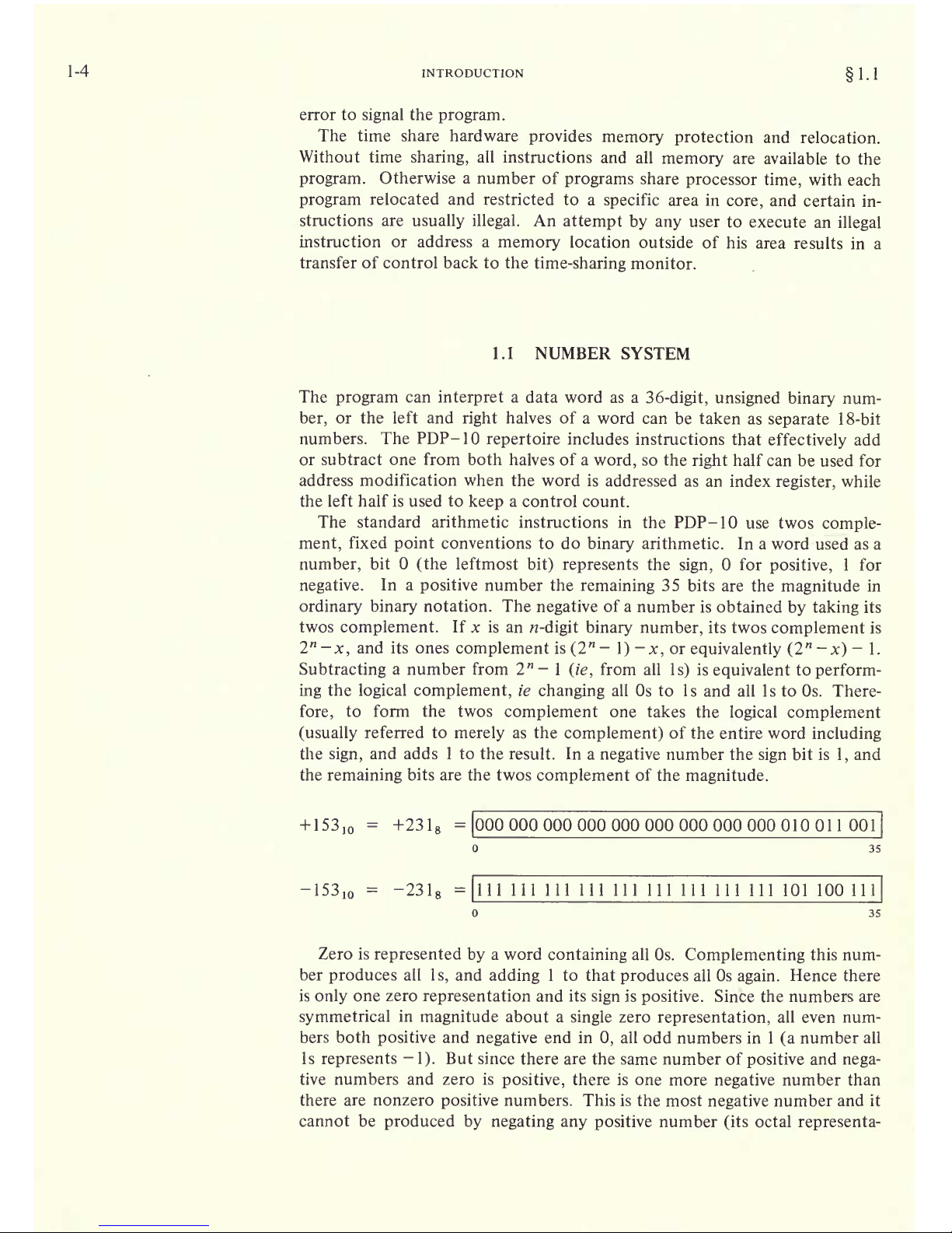
The standard arithmetic
instructions in
the PDF- 10 use
twos
comple-
ment,
fixed
point
conventions
to do
binary
arithmetic. In a
word used
as
a
number,
bit
(the
leftmost
bit)
represents
the
sign,
for
positive,
1 for
negative.
In a
positive
number the
remaining
35
bits are the
magnitude
in
ordinary binary
notation.
The
negative
of a
number is
obtained
by taking
its
twos
complement.
If
x
is
an
-digit binary number,
its twos
complement
is
2"-x,
and its ones
complement is(2"-l)-jc,
or
equivalently
(2"-x)
-
1.
Subtracting
a number from 2"- 1
(ie,
from all
Is)
is
equivalent
to
perform-
ing
the
logical
complement,
ie
changing
all Os
to Is and all Is to Os.
There-
fore,
to form the twos
complement
one takes
the
logical
complement
(usually
referred to
merely
as
the
complement)
of
the entire word
including
the
sign,
and
adds 1 to
the
result.
In a
negative
number the
sign
bit is
1,
and
the
remaining
bits are the twos
complement
of the
magnitude.
+
153,
-
+231
8
-000000000000000000000000000010011001
35
-153,0
=
-231
8
=1111
111 111 111 111
111 111 111 111 101 100111
35
Zero is
represented
by
a word
containing
all Os.
Complementing
this num-
ber
produces
all
Is,
and
adding
1 to that
produces
all Os
again.
Hence there
is
only
one
zero
representation
and
its
sign
is
positive.
Since the numbers
are
symmetrical
in
magnitude
about
a
single
zero
representation,
all even num-
bers both
positive
and
negative
end
in
0,
all odd numbers in 1
(a
number all
Is
represents
-
1).
But
since there are the
same number of
positive
and
nega-
tive numbers
and
zero
is
positive,
there is
one more
negative
number than
there are nonzero
positive
numbers. This is the
most
negative
number
and
it
cannot be
produced by negating any
positive
number
(its
octal
representa-
Page 9
1.1
NUMBER SYSTEM
1-5
tion
is
400000
000000
8
and
its
magnitude
is one
greater
than the
largest
positive
number).
If ones
complements
were used
for
negatives
one could read a
negative
number
by
attaching
significance
to the Os instead of
the
Is. In twos com-
plement
notation
each
negative
number is one
greater
than the
complement
of the
positive
number
of the same
magnitude,
so one can read a
negative
number
by
attaching significance
to the
rightmost
1
and
attaching signifi-
cance
to
the Os at the left of
it
(the
negative
number of
largest magnitude
has
a
1 in
only
the
sign
position).
In a
negative
integer,
Is
may
be discarded at
the
left,
just
as
leading
Os
may
be
dropped
in a
positive
integer.
In a
negative
fraction,
Os
may
be discarded at
the
right.
So
long
as
only
Os are
discarded,
the
number remains in
twos
complement
form because it still
has a 1 that
possesses
significance;
but if a
portion
including
the
rightmost
1 is
discarded,
the
remaining part
of the fraction is now
a
ones
complement.
The
computer
does not
keep
track of a
binary point
the
programmer
must
adopt
a
point
convention and
shift the
magnitude
of the result
to
con-
form
to the convention used.
Two common conventions are to
regard
a
number
as
an
integer
(binary point
at the
right)
or as a
proper
fraction
(binary point
at the
left);
in these two cases the
range
of numbers
repre-
sented
by
a
single
word is 2
35
to 2
35
-
1 or-1 to 1 2~
35
. Since
multiplica-
tion
and division make use of double
length
numbers,
there are
special
instructions
for
performing
these
operations
with
integral operands.
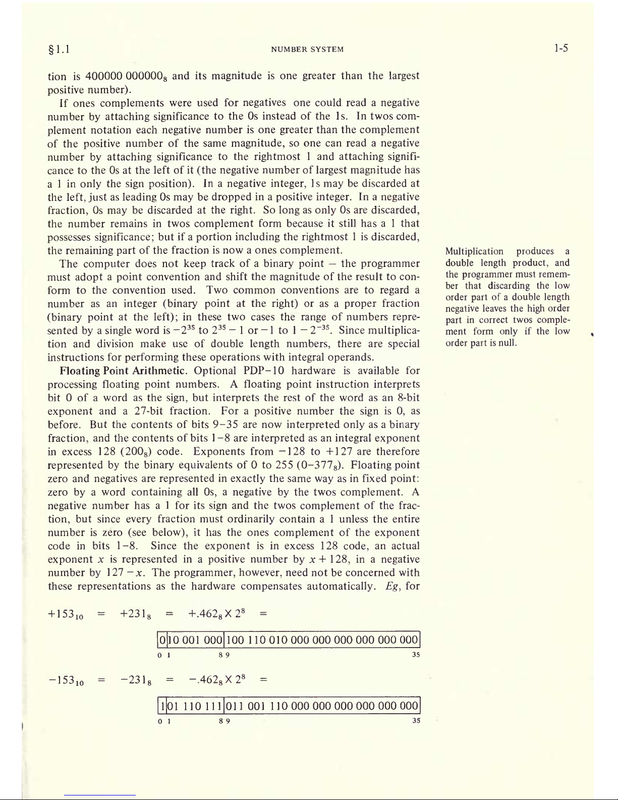
Floating
Point
Arithmetic.
Optional
PDF- 1 hardware is available for
processing
floating
point
numbers.
A
floating point
instruction
interprets
bit of a word
as the
sign,
but
interprets
the
rest
of the word as an 8-bit
exponent
and a 27-bit fraction.
For a
positive
number the
sign
is
0,
as
before.
But the contents
of
bits 9-35
are now
interpreted only
as a
binary
fraction,
and the contents
of
bits 1-8 are
interpreted
as an
integral exponent
in excess
128
(200
8
)
code.
Exponents
from -128 to +127
are
therefore
represented by
the
binary equivalents
of to 255
(0-377
8
).
Floatingpoint
zero and
negatives
are
represented
in
exactly
the same
way
as
in
fixed
point:
zero
by
a word
containing
all
Os,
a
negative by
the twos
complement.
A
negative
number
has a 1 for its
sign
and the twos
complement
of
the frac-
tion,
but since
every
fraction
must
ordinarily
contain a
1
unless the entire
number
is zero
(see below),
it has the ones
complement
of the
exponent
code
in bits 1-8. Since the
exponent
is in excess 128
code,
an
actual
exponent
x is
represented
in a
positive
number
by
x
+
128,
in a
negative
number
by
127
-x.
The
programmer,
however,
need not
be
concerned with
these
representations
as the hardware
compensates automatically. Eg,
for
+
153
10
=
+231
8
=
+.462
8
X2
8
-
Page 10
1-6
INTRODUCTION
1.2
the instruction
that
scales the
exponent,
the
hardware
interprets
the
integral
scale
factor in standard twos
complement
form
but
produces
the
correct
ones
complement
result for
the
exponent.
Except
in
special
cases
the
floating
point
instructions
assume that all
non-
zero
operands
are
normalized,
and
they
normalize a
nonzero
result. A
floating
point
number
is
considered
normalized if
the
magnitude
of
the frac-
tion
is
greater
than or
equal
to
l
/2 and less than 1
.
These numbers
thus
have a
fractional
range
in
magnitude
of
1
A.
to 1
-2"
27
and
an
exponent
range
of
-
1 28 to +127. The hardware
may
not
give
the
correct result if
the
program
supplies
an
operand
that is not
normalized or
that has a
zero fraction
with a
nonzero
exponent.
The
precaution
about truncation
given
for fixed
point
multiplication
applies
to all
floating point
operations
as
they
all
produce
extra
length
results;
but here
the
programmer
may request rounding,
which
automatically
restores the
high
order
part
to twos
complement
form if it
is
negative.
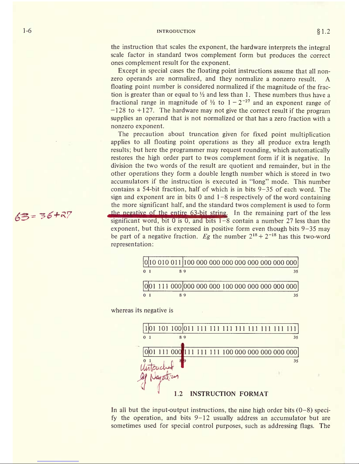
In
division the
two
words of
the result are
quotient
and
remainder,
but in the
other
operations they
form
a double
length
number which is
stored in two
accumulators
if the instruction is
executed in
"long"
mode.
This number
contains
a 54-bit
fraction,
half of which is in bits
9-35 of
each word. The
sign
and
exponent
are in bits and 1 -8
respectively
of
the word
containing
the more
significant
half,
and the standard twos
complement
is
used
to
form
In
the
remaining
part
of the
less
8 contain
a number 27
less
than
the
exponent,
but this is
expressed
in
positive
form
even
though
bits
9-35
may
be
part
of a
negative
fraction.
Eg
the
number
2
18
+
2~
18
has this
two-word
representation:
010
Page 11
1.2
INSTRUCTION FORMAT
1-7
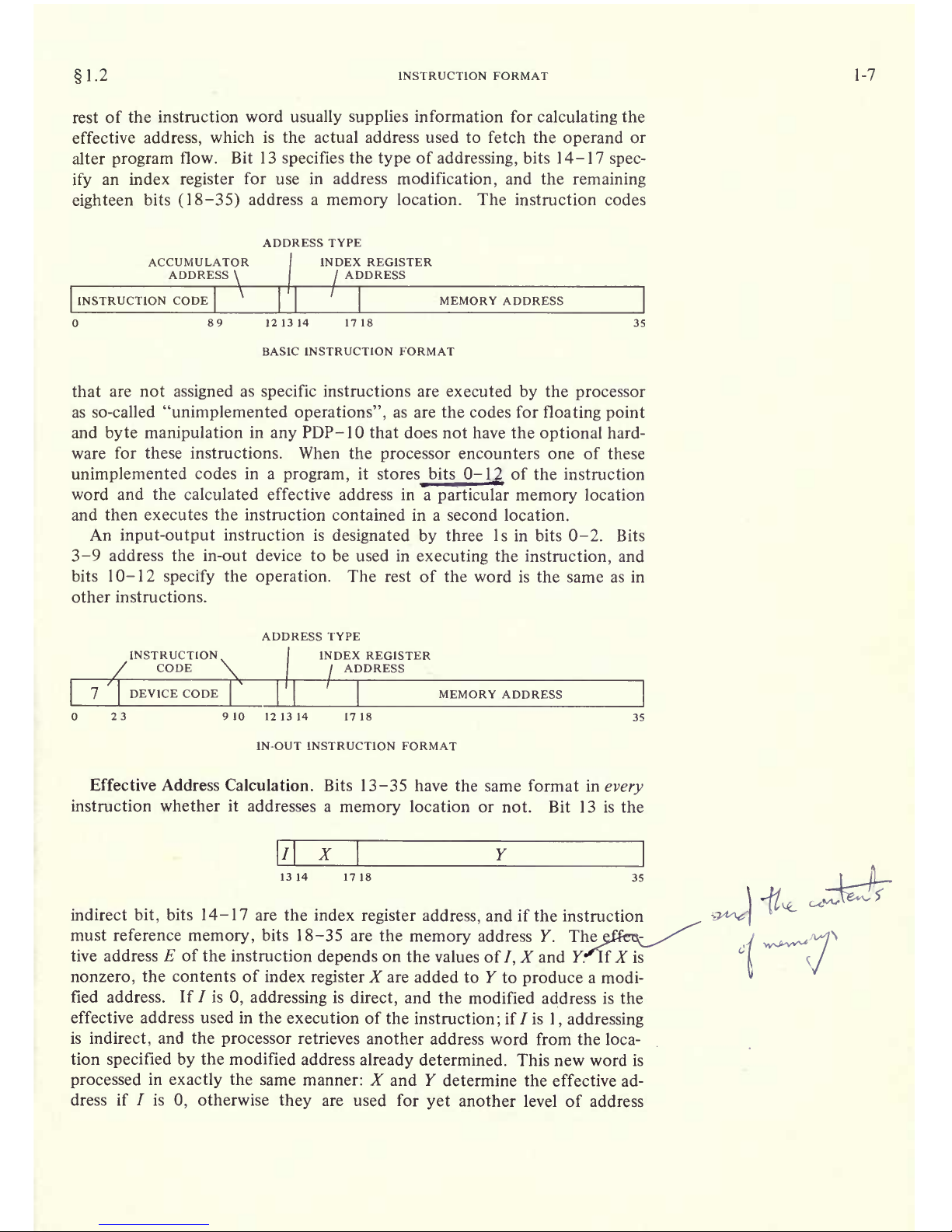
rest of
the instruction
word
usually supplies
information for
calculating
the
effective
address,
which is the actual address used to fetch
the
operand
or
alter
program
flow.
Bit 13
specifies
the
type
of
addressing,
bits 14-17
spec-
ify
an index
register
for use in address
modification,
and the
remaining
eighteen
bits
(18-35)
address
a
memory
location.
The instruction codes
ADDRESS TYPE
ACCUMULATOR
ADDRESS
\
INDEX REGISTER
ADDRESS
INSTRUCTION CODE
Page 12
1-8
INTRODUCTION
1.3
retrieval.
This
process
continues until
some
referenced
location is found
with a in bit
13;
the 18-bit
number
calculated
from the X and Y
parts
of
this
location
is
the
effective
address E.
The calculation
outlined above is
carried
out for
every
instruction
even
if
it
need
not address
a
memory
location. If
the
indirect bit in the
instruc-
tion word
is and no
memory
reference is
necessary,
then
Y
is not
an ad-
dress.
It
may
be a mask
in
some kind
of test
instruction,
conditions to be
sent
to an in-out
device,
or
part
of it
may
be the
number of
places
to shift in
a
shift or rotate instruction or the scale factor in
a
floating
scale instruction.
Even when modified
by
an index
register,
bits
18-35 do not contain an
ad-
dress
when
/ is 0.
But
when /
is
1,
the number
determined from
bits 14-35
is an
indirect address
no
matter what
type
of
information the
instruction
requires,
and
the word retrieved in
any
step
of the calculation
contains an
indirect address
so
long
as /
remains
1 .
When a
location is found in which
/
is
0,
bits 18-35
(perhaps
modified
by
an index
register)
contain the
desired
effective
mask,
effective
conditions,
effective shift
number,
or
effective scale
factor.
Many
of the
instructions
that
usually
reference
memory
for an
oper-
and even have
an
"immediate" mode in which
the result of the effective
address
calculation
is
itself used as a half word
operand
instead of a word
taken from the
memory
location it addresses.
The
important
thing
for
the
programmer
to remember
is
that the same
calculation
is carried out for
every
instruction
regardless
of the
type
of infor-
mation
that must be
specified
for its
execution,
or
even
if the
result
is
ignored.
In the discussion of
any
instruction,
E refers to the actual
quantity
derived
from
/,
X and
Y
and used in the execution of
the
instruction,
be
it
the entire
half word as in the
case
of an
address,
immediate
operand,
mask or
conditions,
or
only part
of it as in a shift
number
or
scale factor.
1.3
MEMORY
All
timing
in the PDF- 10 is
asynchronous.
The internal
timing
for each in-
out
device and each
memory
is
entirely independent
of the
central
processor.
Because core
memory
readout
is
destructive,
every
word read must be
writ-
ten back
in
unless new information
is
to take
its
place.
The basic read-write
cycle
time of the standard
core
memory
is either 1
.00
or 1
.65
microseconds,
but the
processor
need never
wait
the entire
cycle
time. To
read,
it waits
only
until the information is available and then continues its
operations
while
the
memory performs
the write
portion
of the
cycle;
to
write,
it waits
only
until
the data is
accepted,
and the
memory
then
performs
an entire
cycle
to clear and write. To
save time
in an
instruction that fetches
an
oper-
and and
then
writes new data into the same
location,
the
memory
executes
a
read-pause-write
cycle
in
which it
performs
only
the read
part
initially
and
then
completes
the
cycle
when the
processor
supplies
the new data.
Access times for the
accumulator-index
register
locations are decreased
considerably by
substitution of a fast
memory
(contained
in
the
processor)
for
the first sixteen core
locations. Readout is
nondestructive,
so the fast
memory
has no basic
cycle:
the
processor
reads
a
word
directly,
but to write
Page 13
1-3
MEMORY
1-9
it
must
first clear
the
location and
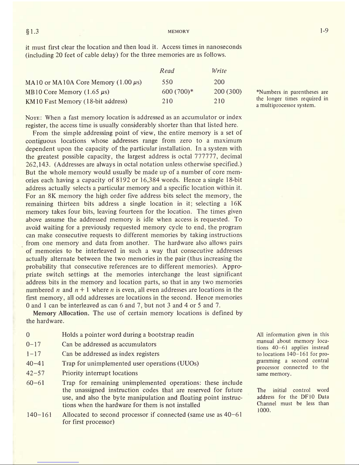
then load it. Access times
in
nanoseconds
(including
20 feet
of cable
delay)
for the
three
memories
are as follows.
MA 1 or
MA
1 OA Core
Memory
(
1 .00
jus)
MB
1
Core
Memory
(
1 .65
jus)
KM
10 Fast
Memory
(
1
8-bit
address)
Read
550
600
(700)*
210
Write
200
200
(300)
210
NOTE:
When
a fast
memory
location
is
addressed
as an
accumulator
or index
register,
the access
time
is
usually
considerably
shorter
than that listed here.
From
the
simple
addressing
point
of
view,
the entire
memory
is a set of
contiguous
locations
whose addresses
range
from zero to a maximum
dependent
upon
the
capacity
of the
particular
installation.
In a
system
with
the
greatest possible
capacity,
the
largest
address
is octal 777777
',
decimal
262,143.
(Addresses
are
always
in octal notation unless otherwise
specified.)
But
the
whole
memory
would
usually
be made
up
of a
number
of core mem-
ories each
having
a
capacity
of
8192 or
16,384
words.
Hence a
single
18-bit
address
actually
selects a
particular memory
and a
specific
location
within it.
For an
8K
memory
the
high
order five address bits select the
memory,
the
remaining
thirteen
bits address a
single
location in
it;
selecting
a 16K
memory
takes
four
bits,
leaving
fourteen
for the
location.
The times
given
above
assume
the addressed
memory
is idle when
access
is
requested.
To
avoid
waiting
for a
previously
requested memory cycle
to
end,
the
program
can
make consecutive
requests
to different memories
by taking
instructions
from one
memory
and
data from another. The hardware also allows
pairs
of memories
to
be interleaved in such a
way
that consecutive
addresses
actually
alternate between the two memories
in the
pair
(thus
increasing
the
probability
that consecutive
references are to different
memories).
Appro-
priate
switch
settings
at the memories
interchange
the least
significant
address
bits in the
memory
and
location
parts,
so that in
any
two memories
numbered
n and n
+
1
where n
is
even,
all even addresses are locations
in the
first
memory,
all odd addresses
are locations in the second. Hence memories
and
1 can be
interleaved as can 6 and
7,
but not 3 and
4
or 5 and
7.
Memory
Allocation.
The use of certain
memory
locations
is
defined
by
the
hardware.
Holds a
pointer
word
during
a
bootstrap
readin
0-17
Can be addressed as accumulators
1-17 Can
be
addressed as index
registers
40-41
Trap
for
unimplemented
user
operations
(UUOs)
42-57
Priority interrupt
locations
60-61
Trap
for
remaining
unimplemented operations:
these include
the
unassigned
instruction codes that are reserved
for future
use,
and also the
byte manipulation
and
floating
point
instruc-
tions when the hardware
for
them is not installed
140-161
Allocated
to second
processor
if
connected
(same
use as 40-61
for first
processor)
*Numbers in
parentheses
are
the
longer
times
required
in
a
multiprocessor
system.
All information
given
in
this
manual
about
memory
loca-
tions
40-61
applies
instead
to
locations
140-161 for
pro-
gramming
a
second central
processor
connected
to the
same
memory.
The
initial control
word
address
for
the DF10
Data
Channel
must be less
than
1000.
Page 14
1-10
INTRODUCTION
1.4
The
assembler
translates
every
statement into
a 36-bit
word,
placing
Os in all bits
whose values
are
unspecified.
1.4
PROGRAMMING
CONVENTIONS
The
computer
has five
instruction
classes:
data
transmission,
logical,
arith-
metic,
program
control and in-out.
The
instructions
in the
in-out
class con-
trol the
peripheral equipment,
and also
control
the
priority
interrupt
and
time
sharing,
control and read
the
processor
flags,
and
communicate with
the
console. The next
chapter
describes all
instructions
mentioned
above,
presents
a
general description
of
input-output,
and
describes
the
effects of
the in-out instructions on the
processor,
priority
interrupt
and
time share
hardware. Effects of in-out
instructions
on
particular
peripheral
devices are
discussed
with
the devices.
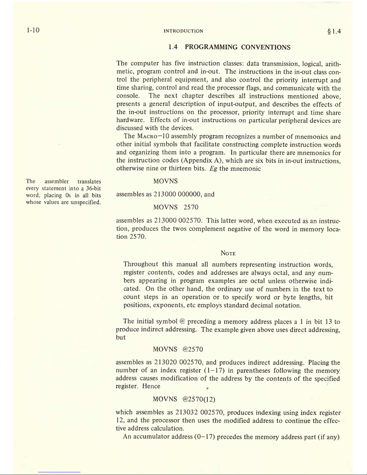
The MACRO-IO
assembly program
recognizes
a
number of
mnemonics and
other
initial
symbols
that
facilitate
constructing
complete
instruction
words
and
organizing
them into a
program.
In
particular
there are
mnemonics for
the
instruction
codes
(Appendix A),
which
are six bits in
in-out
instructions,
otherwise nine or thirteen bits.
Eg
the
mnemonic
MOVNS
assembles as 213000
000000,
and
MOVNS 2570
assembles as 213000 002570.
This
latter
word,
when executed as an
instruc-
tion,
produces
the twos
complement negative
of the
word in
memory
loca-
tion 2570.
NOTE
Throughout
this manual all
numbers
representing
instruction
words,
register contents,
codes and
addresses
are
always
octal,
and
any
num-
bers
appearing
in
program
examples
are octal
unless
otherwise indi-
cated. On
the other
hand,
the
ordinary
use of
numbers in the text to
count
steps
in an
operation
or
to
specify
word or
byte
lengths,
bit
positions, exponents,
etc
employs
standard
decimal notation.
The
initial
symbol
@
preceding
a
memory
address
places
a
1
in bit 13 to
produce
indirect
addressing.
The
example
given
above uses direct
addressing,
but
MOVNS
@2570
assembles as 213020
002570,
and
produces
indirect
addressing. Placing
the
number of an
index
register (1-17)
in
parentheses following
the
memory
address
causes
modification of
the address
by
the contents of the
specified
register.
Hence
,
MOVNS
@2570(12)
which
assembles
as
213032
002570,
produces indexing using
index
register
12,
and the
processor
then
uses
the modified
address to
continue
the
effec-
tive address
calculation.
An
accumulator
address
(0-
1
7)
precedes
the
memory
address
part
(if
any)
Page 15

1
.4
PROGRAMMING
CONVENTIONS
1-11
and
is terminated
by
a comma. Thus
MOVNS
4,@2570(12)
assembles
as 213232
002570,
which
negates
the
word in location E and
stores
the result
in both
E and in accumulator
4. The same
procedure
may
be
used
to
place
Is in bits
9-12
when
these are used for
something
other
than
addressing
an
accumulator,
but mnemonics are available
for this
pur-
pose.
The device
code in an in-out
instruction is
given
in the same
manner as an
accumulator
address
(terminated
by
a comma
and
preceding
the address
part),
but
the
number
given
must
correspond
to the octal
digits
in the word
(000-774).
Mnemonics are however
available for all standard device
codes.
To
control the
priority interrupt system
whose code
is
004,
one
may
give
CONO
4,1302
which assembles
as
700600
0001302,
or
equivalently
CONO
PI,
1302
The
programming
examples
in this manual use the
following addressing
conventions:
*
A colon
following
a
symbol
indicates that it
is a
symbolic
location name.
A:
ADD
6,5704
indicates that
the location that contains ADD
6,5704
may
be addressed
sym-
bolically
as
A.
*
The
period represents
the current
address,
eg
ADD
5,
.+2
is
equivalent
to
A:
ADD
5,A+2
4
Square
brackets
specify
the contents of a
location,
leaving
the address
of
the location
implicit
but
unspecified.
Eg
ADD
12,[7256004]
and
ADD
12,
A
A:
7256004
are
equivalent.
Anything
written at the
right
of
a semicolon is
commentary
that
explains
the
program
but
is not
part
of it.
Page 16

Page 17
Central
Processor
This
chapter
describes
all PDF- 10 instructions but does
not
discuss
the
effects
of
those in-out instructions
that address
specific peripheral
devices.
In the
description
of each
instruction,
the
mnemonic
and name
are
at the
top,
the format is in a box below
them. The mnemonic
assembles
to the
word
in the
box,
where
bits in those
parts
of the
word
represented by
letters
assemble
as Os. The letters
indicate
portions
that must
be added
to the mne-
monic
to
produce
a
complete
instruction
word.
For
many
of the non-IO
instructions,
a
description applies
not
to
a
unique
instruction
with a
single
code in bits
0-8,
but rather to an instruction set
defined
as a basic instruction
that can
be executed
in a
number of modes.
These
modes define
properties subsidiary
to the basic
operation; eg
in data
transmission the mode
specifies
which of the
locations addressed
by
the
in-
struction
is the source and which the destination of the
data,
in test instruc-
tions it
specifies
the
condition
that must be
satisfied for
a
jump
or
skip
to
take
place.
The mnemonic
given
at the
top
is for the basic
mode;
mnemonics
for
the other forms of the instruction are
produced by appending
letters
directly
to the basic
mnemonic.
Following
the
description
is a table
giving
the mnemonics
and
octal codes
(bits 0-8)
for the various modes.
The
processor
execution time for each
instruction
is
also
given
at the
top
unless
the time differs from one mode to another. The time
listed
is that
required
for direct
addressing
without
indexing
(ie
with
no effective address
calculation),
assuming
the instruction and location E
are
both in the same
1.00 microsecond core
memory,
and that an
accumulator is addressed
only
if
necessary
and is in fast
memory.
The
time that can be saved
(if
any)
by
interleaving
or
keeping
instructions
and
operands
in different memories is
indicated
either with the
description
or with
the
discussion
of the modes
preceding
a
group
of instructions. To
determine the exact time
required
for
an
instruction
under
any
circumstances,
refer to the
timing
chart
in
Appendix
C.
In a
description
E
refers to the effective
address,
half word
operand,
mask,
conditions,
shift
number or
scale factor calculated from the
/,
X
and
Y
parts
of the instruction word. In an
instruction that
ordinarily
references mem-
ory,
a reference to E as the
source
of
information means that the instruction
retrieves
the word
contained in location
E;
as a
destination it means the in-
struction stores a word in location E. In
the immediate mode of these
instructions,
the effective half
word
operand
is
usually
treated as a full word
that contains
E in
one half and zero in the
other,
and is
represented
either as
0,E
or
,0
depending
upon
whether E is in the
right
or left half.
2-1
Letters
representing
modes
are
suffixes,
which
produce
new
mnemonics that are rec-
ognized
as distinct
symbols
by
the assembler.
Page 18
2-2
CENTRAL PROCESSOR
2.1
Most of the
non-IO
instructions
can
address an
accumulator,
and in the
box
showing
the format
this
address
is
represented by
A
;
in
the
description,
"AC" refers
to the accumulator addressed
by
A . "AC
left" and "AC
right"
refer to the
two halves of AC.
If an
instruction uses two
accumulators,
these
have addresses
A and
,4
+
1,
where
the
second address is if A is
17. In some
cases
an instruction uses
an
accumulator
only
if A is
nonzero:
a
zero address
in bits
9-12
specifies
no accumulator.
It is assumed
throughout
that time
sharing
is not
in
effect,
and
the
pro-
gram
is unrestricted.
For
completeness,
however,
the
effects of restrictions
on
particular
instructions are
noted;
and execution times are
given
both for
unrestricted
operation
and
t
including relocation
in
a
user
program (the
latter
jtime
is
given
in
parentheses).
2.15 lists all restrictions on
user
programs
and
explains
the
special
effects
produced
by
certain instructions when exe-
cuted
under control
of the monitor while
the
processor
is in
user mode.
Some
simple
examples
are included
with
the instruction
descriptions,
but
more
complex
examples
using
a
variety
of instructions are
given
in 2. 1 1.
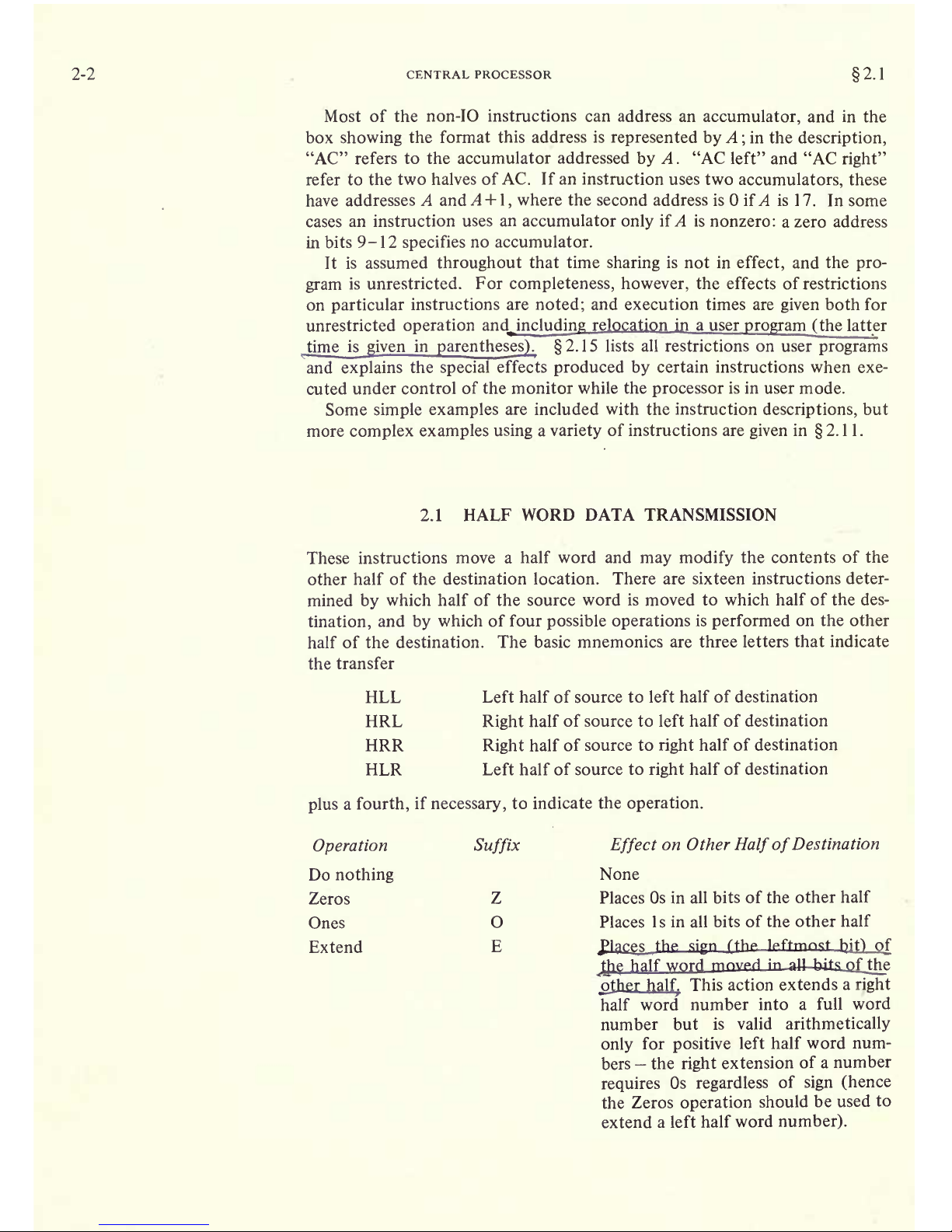
2.1
HALF WORD
DATA TRANSMISSION
These instructions
move a
half word and
may modify
the contents
of the
other
half of the destination location.
There are sixteen instructions
deter-
mined
by
which
half of the source word
is
moved
to which half of the des-
tination,
and
by
which of four
possible
operations
is
performed
on the other
half of
the destination.
The basic mnemonics
are three letters
that indicate
the
transfer
HLL Left
half
of source
to left half of destination
HRL
Right
half
of source to left half of destination
HRR
Right
half of
source to
right
half of destination
HLR
Left half of source
to
right
half of destination
plus
a
fourth,
if
necessary,
to
indicate the
operation.
Operation
Suffix
Effect
on Other
Half
of
Destination
Do
nothing
None
Zeros
Z
Places
Os in all bits of
the other
half
Ones
O
Places Is
in
all
bits of the
other half
Extend
E
Jlgces_Jh
dgn
rthp leftmost
b,jt)
nf
Qie
half
word
mnvpfl
in all
bits
pf
tjv'
other half. This action extends
a
right
half
word number
into a full
word
number but
is valid
arithmetically
only
for
positive
left
half word
num-
bers
the
right
extension
of a
number
requires
Os
regardless
of
sign
(hence
the Zeros
operation
should
be used
to
extend
a left
half word
number).
Page 19
2.1
HALF
WORD DATA TRANSMISSION
2-3
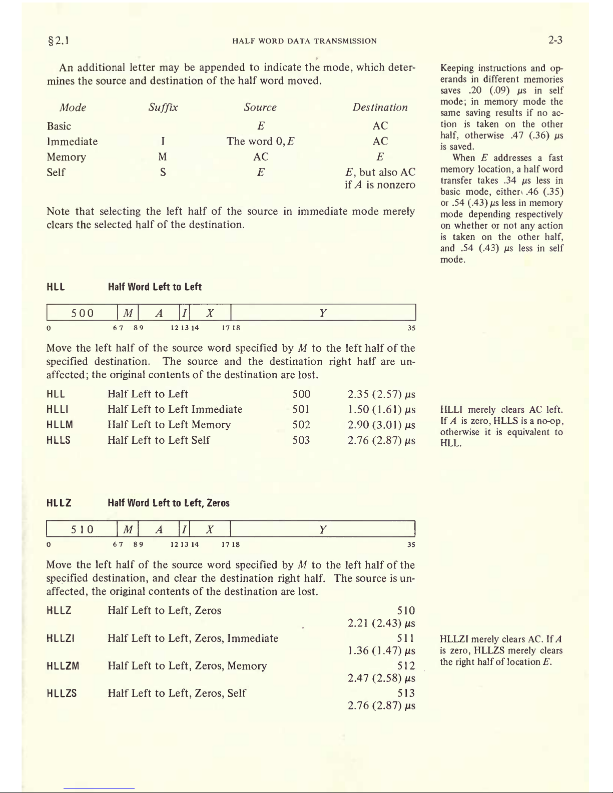
An additional
letter
may
be
appended
to
indicate the
mode,
which deter-
mines
the source
and destination of the half word moved.
Mode
Page 20

2-4
HLLOI sets AC to
all Os in
the left
half,
all
Is
in the
right.
HLLO
CENTRAL
PROCESSOR
Half Word Left to
Left,
Ones
2.1
520
Page 21

2.1
HALF
WORD
DATA
TRANSMISSION
2-5
H R
LM
Half
Right
to Left
Memory
H R LS
Half
Right
to Left
Self
506
2.90
(3.01)
MS
507
2.76
(2.87)
jus
HRLZ
Half Word
Right
to
Left,
Zeros
5
14
Page 22

2-6
CENTRAL PROCESSOR
2.:
specified
destination,
and make all
bits in
the
destination
right
half
equal
to
bit
18 of the source. The
source
is
unaffected,
the
original
contents
of the
destination
are lost.
H R
L E Half
Right
to
Left
,
Extend
HRLEI
Half
Right
to
Left, Extend,
Immediate
H R LEM Half
Right
to
Left, Extend,
Memory
HRLES Half
Right
to
Left, Extend,
Self
534
2.21
(2.43)
jus
535
1.36
(1.47)
MS
536
2.47
(2.58)
MS
537
2.76
(2.87) MS
If
A is
zero,
HRRS is
a
no-op;
otherwise
it
is
equivalent
to
HRR.
HRR
Half Word
RighttoRight
540
Page 23

2.1 HALF WORD
DATA TRANSMISSION
2-7
HRRO
Half Word
Right
to
Right,
Ones
560
Page 24

2-8
CENTRAL PROCESSOR
HLRM Half Left
to
Right
Memory
HLRS Half
Left to
Right
Self
2.1
546
547
2.90
(3.01)
2.76
(2.87)
HLRZI
merely
clears AC
and
is thus
equivalent
to HLLZI.
HLRZ
Half Word Left to
Right,
Zeros
554
Page 25

2.2
FULL
WORD DATA
TRANSMISSION
2-9
bit of
the source. The
source
is
unaffected,
the
original
contents of
the
destination
are lost.
HIRE Half Left to
Right,
Extend
HLREI Half Left to
Right,
Extend,
Immediate
HLREM Half Left
to
Right, Extend,
Memory
HIRES Half Left to
Right, Extend,
Self
574
2.21
(2.43) MS
575
1.36
(1.47)
/is
576
2.47
(2.58) jus
577
2.76
(2.87)
MS
HLREI is
equivalent
to
HLRZI
(it
merely
clears
AC).
EXAMPLES.
The
half
word transmission
instructions
are
very
useful for
handling
addresses,
and
they provide
a
convenient means of
setting
up
an
accumulator whose
right
half is to be
used for
indexing
while a control
count
is
kept
in the left half.
Eg
this
pair
of
instructions loads
the 18-bit numbers
M and N into the
left and
right
halves
respectively
of an
accumulator that is
addressed
symbolically
as XR.
HRLZI
HRRI
XR,M
XR,N
Of
course the source
program
must
somewhere define
the value of
the
symbol
XR as an octal
number
between
1
and 17.
Suppose
that at some
point
we wish to
use the two
halves of XR
inde-
pendently
as
operands
(taken
as
18-bit
positive
numbers)
for
computations.
We can
begin
by moving
XR
left
to the
right
half
of
another
accumulator
AC and
leaving
the
contents of XR
right
alone
in
XR.
HLRZM
HLLI
XR,AC
XR,
;Clear
XR left
It
is not
necessary
to clear the
other half of
XR
when load-
ing
the first half word. But
any
instruction that
modifies
the other half is faster than
the
corresponding
instruction
that does
not,
as the latter
must fetch the destination
word in
order
to
save half
of
it.
(The
difference does not
apply
to self
mode,
for here
the source and destination are
the
same.)
2.2
FULL
WORD DATA
TRANSMISSION
These
are
the
instructions
whose basic
purpose
is to
move one or
more full
words of data from
one
place
to
another,
usually
from an
accumulator to a
memory
location or
vice versa. In a
few cases
instructions
may perform
minor
arithmetic
operations,
such as
forming
the
negative
or the
magnitude
of the word
being processed.
EXCH
Exchange
2.90
(3.01)
MS
250
Page 26
2-10
CENTRAL PROCESSOR
2.2
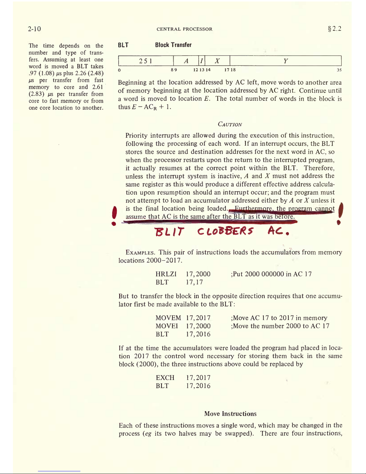
The
time
depends
on the
number and
type
of trans-
fers.
Assuming
at least one
word is moved a BLT takes
.97
(1.08)
MS
plus
2.26
(2.48)
jus
per
transfer from fast
memory
to core
and
2.61
(2.83)
us
per
transfer from
core to fast
memory
or from
one core location to another.
BLT
Block Transfer
25
1
Page 27

2.2
FULL WORD DATA TRANSMISSION
2-11
each
with
four
modes
that
determine
the source and destination of the word
moved.
Mode
Basic
Immediate
Memory
Self
Suffix
I
M
S
Source
E
The word
0,
AC
E
Destination
AC
AC
E
E,
but also AC
if A is nonzero
Keeping
instructions and
op-
erands
in different
memories
saves .47
(.36)
/is
in
memory
mode,
.20
(.09)
MS
in self
mode.
When
E
addresses a fast
memory
location,
a move in-
struction takes .34
MS
less in
basic
mode,
.46
(.35)
MS
less
in
memory
mode,
.54
(.43)
MS
less in self mode.
MOVE
Move
200
Page 28
2-12
CENTRAL PROCESSOR
2.:
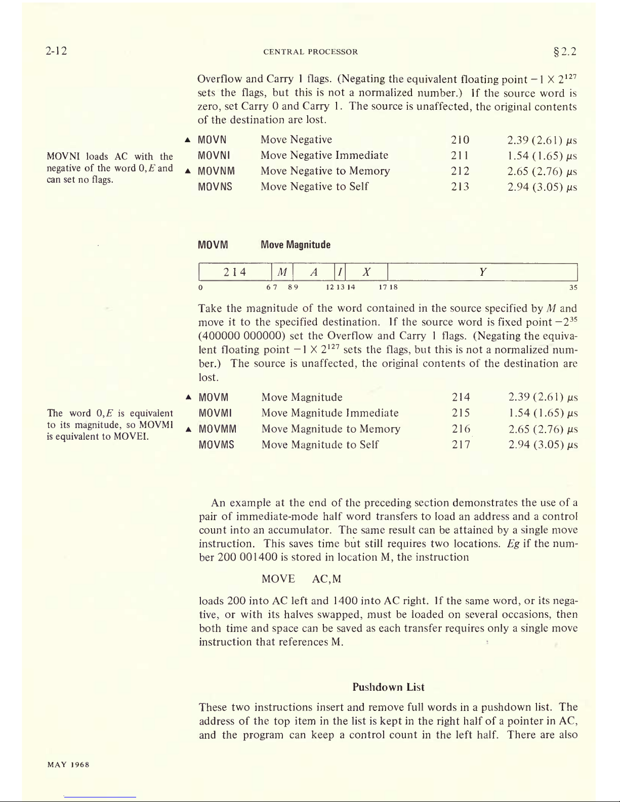
MOVNI
loads
AC
with the
negative
of the
word
0,E
and
can set no
flags.
Overflow
and
Carry
1
flags.
(Negating
the
equivalent
floating point
-1
X
2
127
sets the
flags,
but
this is not
a
normalized
number.)
If
the source word
is
zero,
set
Carry
and
Carry
1.
The source is
unaffected,
the
original
contents
of
the destination
are lost.
MOVN
Move
Negative
MOVNI
Move
Negative
Immediate
MOVNM
Move
Negative
to
Memory
MOVNS
Move
Negative
to Self
210
2.39
(2.61)
MS
211
1.54(1.65)MS
212
2.65
(2.76) MS
213
2.94
(3.05) MS
The word
0,"
is
equivalent
to its
magnitude,
so MOVMI
is
equivalent
to MOVEI.
MOVM
Move
Magnitude
2 14
Page 29
2.2
FULL WORD
DATA TRANSMISSION
2-13
two
subroutine-calling
instructions that utilize
a
pushdown
list of
jump
ad-
dresses
[
2.9]
.
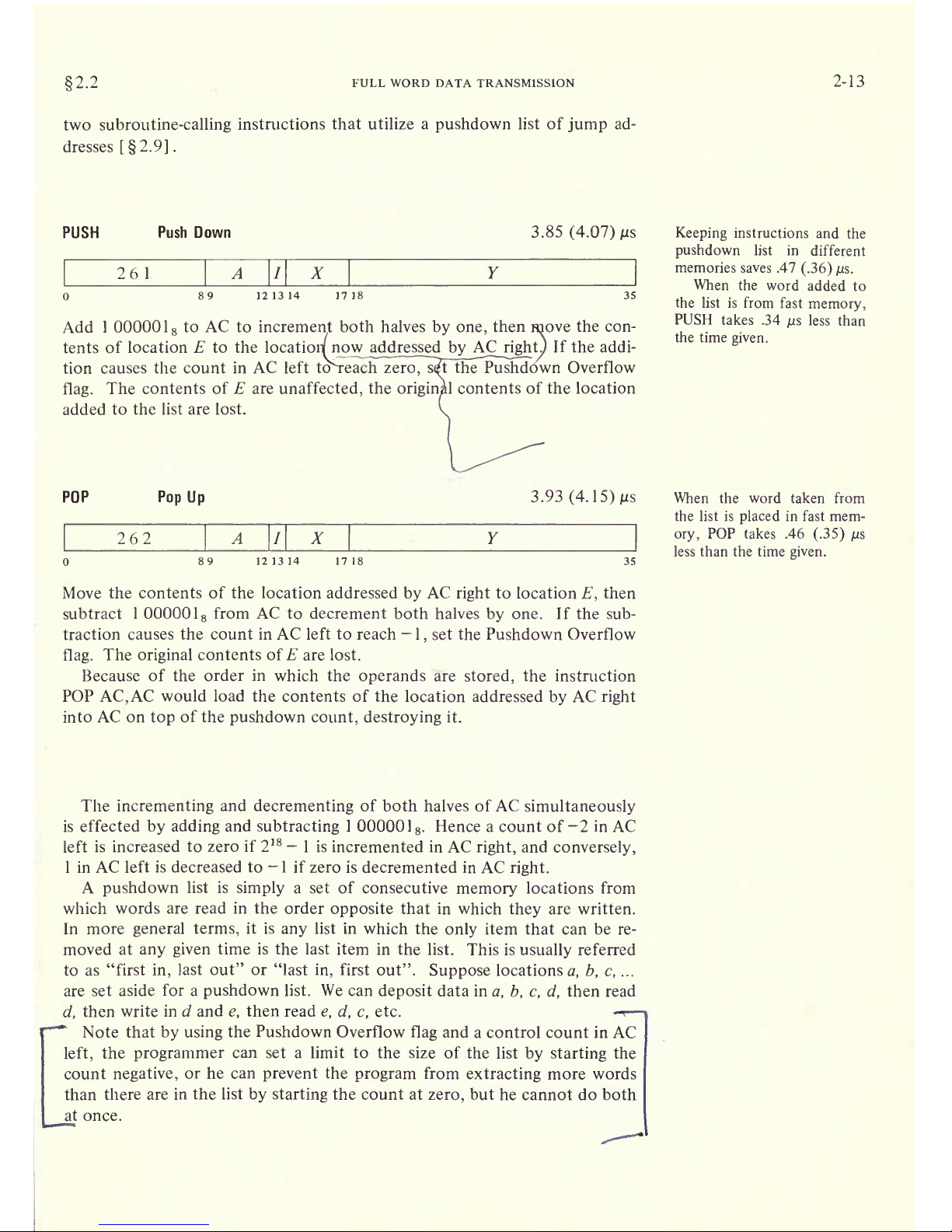
PUSH Push
Down 3.85
(4.07)
261
Page 30

2-14
CENTRAL
PROCESSOR
2.2
Pushdown
storage
is
very
convenient
for a
program
that can
use data
stored in this manner
as
the
pointer
is
initialized
only
once
and
only
one
accumulator
is
required
for the most
complex pushdown
operations.
To
ini-
tialize a
pointer
P
for a
list
to be
kept
in a
block of
memory beginning
at
BLIST and to contain
at most N
items,
the
following
suffices.
MOVSI
P,-/V
HRRI
P,BLIST-1
Of
course the
programmer
must define BLIST
elsewhere and set
aside loca-
tions
BLIST to BLIST
+
N
-
\.
Using
MACRO to full
advantage
one could
instead
give
MOVE
P,[IOWD
7V,BLIST]
where the
pseudoinstruction
IOWD
J,K
is
replaced
by
a word
containing
-J in
the left half
and K
-
1 in
the
right.
Elsewhere
there would
appear
BLIST:
BLOCK TV
which defines BLIST as the current contents of
the location counter and
sets
aside
the TV locations
beginning
at
that
point.
In the POP- 10 the
pushdown
list is
kept
in
a random access
core mem-
ory,
so the restrictions on order of
entry
and removal of items
actually apply
only
to the standard
addressing
by
the
pointer
in
pushdown
instructions
-
other
addressing
methods can
reference
any
item at
any
time. The
most
convenient
way
to do this is to use the
right
half of
the
pointer
as an index
register.
To move the last
entry
to
accumulator
AC
we need
simply
give
MOVE
AC,(P)
Of course this does not shorten the list
the word moved remains
the last
item
in it.
One
usually
regards
an
index
register
as
supplying
an additive factor for
a
basic address contained in an instruction
word,
but the
index
register
can
supply
the basic address and the instruction the additive factor. Thus we can
retrieve
the next to last
item
by
giving
MOVE
AC,-1(P)
and so
forth.
Similarly
PUSH
P,-3(P)
adds the third to last item to
the
end of the
list;
POP
P,-2(P)
removes
the last
item and inserts
it in
place
of the next to last item
in the
shortened
list.
Page 31

2.3
BYTE MANIPULATION
2-15
2.3
BYTE
MANIPULATION
This set
of five instructions allows the
programmer
to
pack
or
unpack
bytes
of
any length anywhere
within a word. Movement of a
byte
is
always
between AC and a
memory
location:
a
deposit
instruction takes
a
byte
from
the
right
end of AC and inserts
it
at
any
desired
position
in the
memory
location;
a load instruction
takes
a
byte
from
any position
in
the
memory
location
and
places
it
right-justified
in
AC.
The
byte manipulation
instructions
have the standard
memory
reference
format,
but the effective address E
is
used to retrieve
a
pointer,
which
is
used
in turn
to
locate
the
byte
or
the
place
that will
receive
it. The
pointer
has
the
format
p
Page 32

2-16
CENTRAL
PROCESSOR
2.3
Keeping
the
pointer
in fast
memory
saves .34
jus.
Taking
bytes
from a
fast
memory
location
saves
another .34
/us.
LDB
Load
Byte
4.02(4.35)
+
A5(P
+
S) [+.26]
/us
135
Page 33

2.4 LOGIC
2-17
the
right
S bits of AC
into the location and
position specified
by
the
newly
incremented
pointer.
The
original
contents of
the bits that receive the
byte
are
lost,
AC and
the
remaining
bits of
the
deposit
location are
unaffected.
Note that
in
the
pair
of
instructions that both
increment the
pointer
and
process
a
byte,
it is
the
modified
pointer
that determines
the
byte
location
and
position.
Hence to
unpack bytes
from a block of
memory,
the
program
should set
up
the
pointer
to
point
to a
byte
just
before
the
first
desired,
and
then load them with
a
loop containing
an
ILDB.
If
the
first
byte
is at
the
left end of a
word,
this is most
easily
done
by initializing
the
pointer
with a
P of 36
(44
8
).
Incrementing
then
replaces
the 36 with
36 S to
point
to the
first
byte.
At
any
time that
the
program
might
inspect
the
pointer during
execution
of
a series of
ILDBs or
IDPBs,
it
points
to the last
byte processed
(this
may
not
be true when
the
pointer
is
tested from an
interrupt
routine
[2.13]).
Special
Considerations.
If
S is
greater
than P
and also
greater
than
36,
incrementing
produces
a
new
P
equal
to
lOO-S
rather than
36-5. For
S>
36
the
byte
is at most
the entire
word;
for />
36 no
byte
is
processed
(loading
merely
clears
AC).
If both P
and
S
are
less than 36
but P
+
S >
36,
a
byte
of size 36
-
P is
loaded from
position
P. or
the'right
36
-
P
bits of the
byte
are
deposited
in
position
P.
2.4 LOGIC
For
logical
operations
the PDF-
10 has
instructions for
shifting
and
rotating
as well as for
performing
the
complete
set of
sixteen Boolean
functions
of
two variables
(including
those
in
which the
result
depends
on
only
one or
neither
variable).
The
Boolean functions
operate
bitwise on
full
words,
so
each instruction
actually performs
thirty-six logical
operations
simultane-
ously.
Thus in the
AND function of two
words,
each bit of
the
result
is
the
AND of the
corresponding
bits of
the
operands.
The
table on
page
2-23 lists
the
bit
configurations
that
result from the
various
operand
configurations
for
all instructions.
Each Boolean instruction
has four modes
that
determine
the
source of the
non-AC
operand,
if
any,
and
the destination
of the
result.
Mode
Basic
Immediate
Memory
Both
Suffix
I
M
B
Source
of
non-
AC
operand
The
word
0,
E
E
Destination
of
result
AC
AC
E
AC and E
Keeping
instructions and
op-
erands in different
memories
saves .47
(.36)
p.s
in
memory
and both
modes in the first
four of these
instructions
(those
that have no
operand
or
only
an
AC
operand),
.20
(.09)
/us
in
memory
and both
modes in the
remaining
twelve
(those
that have a
memory
or
immediate
op-
erand).
Page 34

2-18 CENTRAL PROCESSOR
2.4
A Boolean
instruction in
which E
addresses a fast
memory
location
takes .46
(.35)
M
S less in
memory
or
both mode if it
has no
oper-
and or
only
an AC
operand.
If it has
a
memory
operand,
it
takes .34
/us
less in basic
mode,
.54
(.43)
MS
less in
memory
or both
mode.
SETZ
and SETZI
are
equiva-
lent
(both
merely
clear
AC).
MACRO also
recognizes
CLEAR,
CLEARI,
CLEARM
and CLEARS
as
equivalent
to
the
set-to-zeros
mnemonics.
For an instruction without an
operand
(one
that
merely
clears a
location
or
sets it to all
Is)
the modes
differ
only
in
the
destination of
the
result,
so
basic and immediate modes
are
equivalent.
The
same
is
true
also of an
instruction
that uses
only
an AC
operand.
When
specified by
the
mode,
the
result
goes
to the accumulator
addressed
by
A,
even when
there is no AC
operand.
SETZ
Set
to Zeros
400
Page 35

2.4
SETCA
LOGIC
Set
to
Complement
of AC
450
Page 36

2-20
CENTRAL PROCESSOR
2.4
AND
And with AC
404
Page 37

2.4
ANDCB
LOGIC
And
Complements
of Both
440
Page 38

2-22
CENTRAL PROCESSOR
2.4
ORCM
Inclusive Or
Complement
of
Memory
with
AC
464
Page 39

2.4 LOGIC
2-23
EQV
Equivalence
with
AC
444
M
X
67 89
121314 1718
35
Change
the contents of the
destination
specified by
M to the
complement
of
the exclusive OR function of
the
specified
operand
and AC
(the
result has Is
wherever the
corresponding
bits of the
operands
are the
same).
EQV
Equivalence
444
2.35
(2.57)
jus
EQVI
Equivalence
Immediate
445
1.50
(1.61) jus
EQVM
Equivalence
to
Memory
446 2.90
(3.01) /us
EQVB
Equivalence
to Both
447
2.90
(3.01) jus
The
original
contents of the
destination can
be recovered
except
in
EQVB,
where
both
operands
are
replaced by
the
result.
In
the other
three modes
the
replaced operand
is
restored
by repeating
the
instruction in the
same
mode,
ie
by taking
the
equivalence
function of
the
remaining
operand
and
the result.
For the
four
possible
bit
configurations
of
the two
operands,
the
above
sixteen instructions
produce
the
following
results. In
each case the result as
listed is
equal
to bits
3-6 of the instruction
word.
AC
Mode
Specified
Operand
Page 40

2-24
CENTRAL
PROCESSOR
2.4
Shift and
Rotate
The
remaining
logical
instructions
shift or
rotate
right
or left
the
contents
of
AC or the contents of two
accumulators,
A and A
+
l
(mod
20
8
),
concat-
enated into a 72-bit
register
with
A on
the
left.
The
illustration
below
shows the
movement
of
information
these
instructions
produce
in
the accu-
LSH
Page 41

2.4
LOGIC
mulators.
In a
(logical)
shift the contents
of a
register
are moved bit-to-bit
with
Os
brought
in at the end
being
vacated;
information shifted out
at the
other
end
is
lost.
[For
a discussion
of
arithmetic
shifting
see
2.5J
In-
rotation
the
rnrrtnrb
nrp mnvi il
i
ji
Hi
.illy
'lui'li
thnt
intnrmntinn
rotated out
in at the
other.
The
number of
places
moved is
specified by
the result of the effective
address calculation taken
as
a
signed
number
(in
twos
complement
notation)
modulo
2
8
in
magnitude.
In other words the effective shift E
is
the number
composed
of bit 18
(which
is the
sign)
and
bits
28-35
of the calculation
result. Hence the
programmer may specify
the shift
directly
in
the instruc-
tion
(perhaps
indexed)
or
give
an indirect
address
to
be used
in
calculating
the
shift. A
positive
E
produces
motion to
the
left,
a
negative
E
to the
right;
maximum movement
is 255
places.
____
2-25
LSH
Logical
Shift Left:
Right:
Page 42

2-26
CENTRAL
PROCESSOR
i2.5
ROTC
Rotate
Combined
Left:
2.00(2.11)
+
.15||/us
Right:
1.84(1.95)"+ .15||
jus
245
Page 43

2.5 FIXED POINT ARITHMETIC
2-27
instructions
[2.14])
that can
request
a
priority interrupt
if enabled. The
conditions
detected can
only
set
the
flags
and the hardware does not clear
them,
so the
program
must clear them before an instruction if
they
are to
give
meaningful
information
about the instruction afterward.
However,
the
program
can check the
flags
following
a series of instructions to determine
whether
the entire
series
was
free of the
types
of error detected.
All but the shift instructions
have four modes that determine the source
of the non-AC
operand
and the
destination of the result.
Mode
Basic
Immediate
Memory
Both
Suffix
I
M
B
Source
of
non-
AC
operand
Page 44

2-28
CENTRAL
PROCESSOR
2.5
Keeping
instructions and
op-
erands in different memories
saves .20
(.09) MS
in
SUBM
and
SUBB.
When E
addresses a fast
memory
location,
SUB takes
.34
us
less
than
the
time
given,
SUBM
and SUBB
take
.54
(.43)
/us
less.
Keeping
instructions
and
op-
erands in different
memories
saves .47
(.36)
jus
in
MULM,
.31
(.20)
MS
in MULB.
When E
addresses a fast
memory
location,
MUL
takes
.34
/us
less
than the time
given,
MULM
takes .80
(.69)
MS
less,
and MULB
takes .64
(.53)
MS
less.
SUB
Subtract
SUBI
Subtract
Immediate
SUBM
Subtract to
Memory
SUBB
Subtract
to Both
MUL
Multiply
274
2.
53
(2.
75)
MS
275
1.68
(1.79)
MS
276
3.08
(3. 19)
MS
277
3.08
(3.
19)
MS
224
Page 45

2.5
FIXEDu POINT ARITHMETIC
2-29
IMUL
Integer
Multiply
IMULI
Integer
Multiply
Immediate
IMULM
Integer
Multiply
to
Memory
IMULB
Integer
Multiply
to Both
220 9.59
(9.81)
jus
221 8.09
(8.20) jus
222 10.56
(10.78)
MS
223 10.56
(10.78)
/is
Timing.
The times
given
above
are
average.
Refer to the
description
of
MUL for the
timing
effects of the
multiplication algorithm.
Minimum times
with a zero
multiplier
are
IMUL
IMULI
IMULM
IMULB
8.42
(8.64) MS
7.57
(7.68)
MS
9.39
(9.61)
MS
9.39
(9.61) MS
These must be increased
by
.13
MS
for each transition. The
programmer
can
minimize
the time
by using
as the
multiplier
the
operand
with fewer transi-
tions.
Keeping
instructions
and
op-
erands in different
memories
saves .47
(.36)
jus
in IMULM
and IMULB.
When E addresses
a fast
memory
location,
IMUL
takes
.34
jus
less than the time
given,
IMULM and IMULB
take .80
(.69)
jus
less.
DIV
Divide
234
Page 46

2-30
CENTRAL PROCESSOR 2.5
the unrounded
quotient
in
the
specified
destination.
If
M
specifies
AC as the
destination,
place
the
remainder,
with
the same
sign
as the
dividend,
in
accumulator
A
+
1 .
Keeping
instructions and
op-
erands in different memories
saves .5
(.4)
/ts
in
IDIVM,
.3
(.2)
us
in IDIVB.
When E addresses a fast
memory
location,
IDIV takes
.3
MS
less than the time
given,
IDIVM takes .8
(.7)
MS
less,
and
IDIVB takes .6
(.5)
/is
less.
If the division is not
per-
formed,
only
3-3.5
/is
are
required.
IDIV
Integer
Divide
I D
I VI
Integer
Divide Immediate
IDIVM
Integer
Divide to
Memory
IDIVB
Integer
Divide to Both
230 16.5
(16.7)
/is
231 15.7
(15.
8)
MS
232 17.4
(17.6)
MS
233
17.4
(17.6) MS
EXAMPLE.
The
integer multiply
and divide instructions
are
very
useful for
computations
on addresses or character
codes,
or
performing any
integral
operations
in
which the result is small
enough
to be accommodated
in a
single register.
As an
example suppose
we wish to determine
the
parity
of the
8-bit
char-
acter
abcdefgh,
where
the letters
represent
the bits of the character.
Assum-
ing
the character
is
right-justified
in
AC,
we
first
duplicate
it twice to the left
producing
abc
def gha
bed
efg
hob cde
fgh
where
the bits
(in
positions
12-35)
are
grouped corresponding
to the
octal
digits
in the
word.
Anding
this with
001 001 001 001 001 001 001 001
retains
only
the least
significant
bit in each 3-bit
set,
so we can
represent
the
result
by
cfadgbeh
where each
letter
represents
an octal
digit having
the same value
(0
or
1)
as
the
bit
originally represented by
the same letter.
Multiplying
this
by
llllllllg
generates
the
following
partial
products:
cfadgbeh
cfadgbeh
cfadgbeh
cfadgbeh
cfadgbeh
cfadgbeh
cfadgbeh
cfadgbeh
Since
any
digit
is at most
1
,
there can be no
carry
out of
any
column
with
fewer
than
eight
digits.
Hence the
octal
digit
produced
by
summing
the
center
column
(the
one
containing
all the bits of
the
character)
is even or
odd
as the sum
of the
bits is even or odd. Thus
its least
significant
bit
(bit
14
of the
low order
word in the
product)
is the
parity
of the
character,
if
even,
1 if odd.
The above
may
seem
a
very complicated procedure
to do
something
trivial,
but it
is effected
by
this
quite simple
sequence
(with
the
character
Page 47

2.5
FIXED POINT ARITHMETIC
2-31
right-justified
in
AC)
:
IMULI
AC,
200401
AND
AC.ONES
IMUL
AC,
ONES
ONES:
11111111
where
the
parity
is
indicated
by
AC bit
14.
Of
course, following
the IMUL
would be
a
test instruction to check
the value of the
bit.
Arithmetic
Shifting
These two instructions
produce
an arithmetic shift
right
or left of the num-
ber in
AC or
the double
length
number
in
accumulators
A
and
A
+
1
.
Shifting
is the
movement of the
contents of a
register
bit-to-bit. The
operation
dis-
cussed
here is similar to
logical
shifting
[see
2.4 and
the illustration on
page
2-24]
,
butinan arithmetic shift
only
the
magnitude part
is
shifted
-
the
sign
is
unaffected.
In a
double
length
number
the 70-bit
string
made
up
of
the
magnitude
parts
of the two
words is
shifted,
but the
sign
of the low
order
word is made
equal
to the
sign
of the
high
order
word.
Null bits are
brought
in at the end
being
vacated:
a
left
shift
brings
in Os at
the
right,
whereas a
right
shift
brings
in the
equivalent
of the
sign
bit at
the
left.
In
either
case,
information shifted out at the other
end
is
lost.
A
single
shift left is
equivalent
to
multiplying
the
number
by
2
(provided
no bit of
significance
is shifted
out);
a shift
right
divides the number
by
2.
The number
of
places
shifted is
specified by
the result of the
effective
address
calculation
taken as a
signed
number
(in
twos
complement
notation)
modulo
2
8
in
magnitude.
In other words
the effective shift E is the
number
composed
of bit
18
(which
is the
sign)
and bits 28-35 of
the calculation
result.
Hence
the
programmer may
specify
the shift
directly
in
the instruc-
tion
(perhaps
indexed)
or
give
an
indirect address
to
be used in
calculating
the shift.
A
positive
E
produces
motion to the
left,
a
negative
E to the
right;
E
is thus the
power
of
2
by
which the
number
is
multiplied.
Maximum
movement
is 255
places.
ASH
Arithmetic
Shift Left: 1.62
(1.73)
+
.\5\E\
MS
Right:
1.46(1.57)
+
.\5\E\ns
240
Page 48

2-32
CENTRAL PROCESSOR
2.6
ASHC
Arithmetic Shift Combined
Left:
Right:
Page 49

2.6
FLOATING POINT ARITHMETIC
2-33
normalization if the
original
operands
are normalized.
An
extra
quotient
bit
is calculated for
rounding
when
requested
;
long
mode retains the remainder.
The
processor
has
four
flags, Overflow, Floating
Overflow,
Floating
Underflow and No
Divide,
that
indicate when the
exponent
is too
large
or
too small to be
accommodated or a
division cannot be
performed
because of
the relative values of
dividend and
divisor.
Any
of these
circumstances
sets
Overflow and
Floating
Overflow.
If
only
these
two
are
set,
the
exponent
of
the answer is too
large;
if
Floating
Underflow is also
set,
the
exponent
is too
small.
No
Divide
being
set
means the
processor
failed to
perform
a
division,
an event that can be
produced
only
by
a zero divisor if all
nonzero
operands
are normalized. These
flags
can be read
and controlled
by
certain
program
control instructions
[2.9]
,
and
Overflow and
Floating
Overflow are avail-
able
as
processor
conditions
(via
in-out instructions
[2.14])
that
can
request
a
priority
interrupt
if
enabled. The
conditions detected can
only
set
the
flags
and the
hardware does not
clear
them,
so
the
program
must clear
them before a
floating
point
instruction if
they
are to
give
meaningful
infor-
mation about the instruction
afterward.
However,
the
program
can
check
the
flags following
a
series of
instructions to
determine whether the entire
series
was free of the
types
of error
detected.
The
floating
point
hardware
functions at
its best
if
given
operands
that
are either normalized or
zero,
and
except
in
special
situations
the hardware
normalizes a nonzero result. An
operand
with a zero fraction
and a nonzero
exponent
can
give
wild
answers in
additive
operations
because
of
extreme
loss of
significance; eg
adding
&
X
2
2
and X
2
69
gives
a zero
result,
as the
first
operand
(having
a smaller
exponent)
looks
smaller to the
processor
and
is
shifted
to oblivion. A
number with
a
1
in bit and Os
in bits
9-35 is not
simply
an incorrect
representation
of
zero,
but rather an
unnormalized
"fraction"
with
value
-
1 .
This
unnormalized number can
produce
an incor-
rect answer in
any operation.
Use of
other
unnormalized
operands
simply
causes loss of
significant
bits,
except
in division where
they
can
prevent
its
execution because
they
can
satisfy
a no-divide
condition that is
impossible
for normalized numbers.
The
processor
normalizes the
result
by
shifting
the fraction
and
adjusting
the
exponent
to
compensate
for the
change
in
value.
Each shift and accom-
panying exponent
adjustment
thus
multiply
the number
both
by
2 and
by
l
h.
simulta-
neously,
leaving
its
value un-
changed.
Scaling
One
floating point
instruction
is
in a
category by
itself:
it
changes
the
exponent
of a number
without
changing
the
significance
of the
fraction.
In
other words it
multiplies
the number
by
a
power
of
2,
and is thus
analogous
to arithmetic
shifting
of fixed
point
numbers
except
that no
information is
lost, although
the
exponent
can overflow or
underflow. The amount
added
to the
exponent
is
specified by
the
result of the
effective address
calculation
taken as a
signed
number
(in
twos
complement
notation)
modulo
2
8
in
mag-
nitude.
In other
words the
effective scale factor E
is the
number
composed
of bit 18
(which
is
the
sign)
and bits 28-35 of
the calculation
result.
Hence
the
programmer
may
specify
the factor
directly
in the
instruction
(perhaps
indexed)
or
give
an indirect address to
be used in
calculating
it. A
positive
E
increases the
exponent,
a
negative
E
decreases
it;
E is
thus the
power
of 2
by
which the number
is
multiplied.
The
scale factor lies in the
range
-256
to
+255.
Page 50

2-34
CENTRAL PROCESSOR
2.6
TV is the
number of left shifts
needed to normalize the
result.
This instruction can be
used
to float
a fixed number with
27 or
fewer
significant
bits.
To
float an
integer
contained
within AC
bits
9-35,
FSC
AC,
233
inserts the correct
exponent
to move the
binary point
from the
right
end to the left
of bit 9 and then normalizes
(233
8
=
155,o
=
128
+
27).
FSC
Floating
Scale
2.75(2.86)4-
.257V
jus
132
Page 51

2.6
FLOATING POINT ARITHMETIC
2-35
tion and
rounding
is
tested for overflow
or underflow.
If
the
exponent
is
>
127,
set Overflow and
Floating
Overflow;
the result stored
has
an
expo-
nent
256
less than the correct
one. If
<-128,
set
Overflow,
Floating
Over-
flow and
Floating
Underflow;
the result
stored
has
an
exponent
256
greater
than the correct one.
FADR
Floating
Add and
Round
144
Page 52

2-36
Use of
normalized
operands
requires
at most one
normali-
zation
step,
for the
result. If
unnormalized
operands
are
used,
all times
must be in-
creased
by
.25./V.
FMPR
CENTRAL
PROCESSOR
Floating
Multiply
and
Round
2.6
1 64
Page 53

2.6
FLOATING POINT
ARITHMETIC
2-37
exponent
overflow or
underflow
as
described
above,
and
place
the result in
the
specified
destination.
FDVR
Floating
Divide and
Round
FDVRI
Floating
Divide
and
Round
Immediate
FDVRM
Floating
Divide
and
Round to
Memory
FDVRB
Floating
Divide
and
Round to Both
174
14.1
(14.3)
jus
175
13.3
(13.4)
jus
176
15.1
(15.3)
MS
177
15.1
(15.3) MS
If
unnormalized
operands
are
used,
all
times
must be in-
creased
by
.257V. If the
divi-
sion is not
performed,
only
3.5-4
/us
are
required.
Operations
without
Rounding
Instructions that do
not round
are faster
for
processing floating
point
num-
bers
with
fractions
containing
fewer than 27
significant
bits. On
the other
hand the
long
mode
provides
double
precision
or
allows the
programmer
to
use his own method of
rounding.
Besides the
four usual
arithmetic
opera-
tions with
normalization,
there
are two
nonnormalizing
instructions that
facilitate
double
precision
arithmetic
[2.1
1
gives
examples
of
double
preci-
sion
floating
point
routines]
.
These two
instructions have no
modes.
DFN Double
Floating Negate
3.43
(3.54) MS
131
|
A
Page 54

2-38
The
exponent
of
the
sum
is
equal
to that of
the
larger
summand unless
addition of
the
fractions
overflows,
in
which case it
is
greater by
1.
Exponent
overflow can
occur
only
in the
latter case.
CENTRAL
PROCESSOR
2.6
NOTE
The result
is
placed
in
accumulator A+l . This is
the
only
arithmetic instruction that stores the
result
in a second
accumulator, leaving
the
original
operands
intact.
If the
exponent
of the sum
following
the
one-step
normalization is >
127,
set
Overflow
and
Floating
Overflow;
the result
stored has an
exponent
256
less
than the correct
one.
Keeping
instructions
and
op-
erands in
different memories
saves .47
(.36)
/us
in
memory
and both
modes.
When E
addresses a fast
memory
location,
a
floating
point
instruction without
rounding
takes .34
MS
less
than
the time
listed
in basic
or
long
mode,
.80
(.69) /us
less in
memory
or both mode.
The
remaining floating point
instructions
perform
the four standard arith-
metic
operations
with normalization
but without
rounding.
All
use
AC and
the contents
of
location
E as
operands
and
have four modes.
Mode
Basic
Long
Suffix
L
Effect
High
order
word of
result
stored in AC.
In
addition,
subtraction and
multiplica-
tion,
the two-word
result
(in
th^d^ouble
length
format described
inB Iis
stored
in accumulators
A
ancft^^^n
division the
dividend is the double leneth
Memory
M
High
order word of result
store/d
in
E.
Both B
'High
order word of result
stored
in AC
and E.
^ifc
l
tw^cT
v
s*<
a.
.
-^UMbw
'rewas&fa
v
In each
of
these
instructions,
the
exponent
that results, from normaliza-
tion
is
tested
for
overflow or underflow. If
the
exponent
is\Z>
127,
set Over-
flow and
Floating
Overflow;
the result stored has an
exponent
256 less than
the correct one.
If
<
-128,
set
Overflow,
Floating
Overflow and
Floating
Underflow;
the result stored has an
exponent
256
greater
than the correct
one.
The time
required
is a function of
the number
N of left shifts needed for
normalization.
FAD
Floating
Add
140
Page 55

2.6
FLOATING POINT ARITHMETIC
2-39
mulators in
long
mode.
Otherwise
normalize the double
length
sum
bringing
Os into bit
positions
vacated at
the
right,
test for
exponent
overflow or
underflow
as
described
above,
and
place
the
high
order word of
the result in
the
specified
destination.
In
long
mode if
the
exponent
of
the sum is > 1 54
(
1
27
+
27)
or <
-
1 1
(-128
+
27)
or
the low
order half
of the
fraction is
zero,
clear AC A
+
\.
Otherwise
place
a low
order
word for a
double
length
result in A
+
l
by
putting
a in bit
0,
an
exponent
in
positive
form
27
less than
the
exponent
of the sum in bits 1
-8,
and
the low
order
part
of the fraction
in bits
9-35.
FAD
Floating
Add
FAD L
Floating
Add
Long
FADM
Floating
Add
to
Memory
FADB
Floating
Add to Both
140
4.46
(4.68)
+
.15D
+
.257V
jus
141
5.3 1
(5.53)
+
.15D
+
. 257V
/us
142
5.43
(5.65)
+
.15D
+
.25N
(is
143
5.43(5.65)
+
.15>
+
.25N
us
D is the
difference between
the
operand exponents pro-
vided
that difference is <
63.
Otherwise D
=
0.
FSB
Floating
Subtract
150
Page 56

2-40
CENTRAL
PROCESSOR
2.6
FMP
Use of
normalized
operands
requires
at most one normali-
zation
step
for the result. If
unnormalized
operands
are
used,
all times must be in-
creased
by
.25N.
Floating Multiply
1
60
Page 57

2.7
ARITHMETIC
TESTING
2-41
is
zero,
clear the destination
specified by
M,
clearing
both accumulators in
long
mode
if the double
length
dividend was zero.
A
quotient
with a non-
zero
fraction
will
already
be
normalized
if
the
original
operands
were
nor-
malized;
if it is
not,
normalize it
bringing
Os into bit
positions
vacated at the
right.
Test for
exponent
overflow or
underflow
as described
above,
and
place
the
single length quotient
part
of the
result
in the
specified
destination.
In
long
mode calculate the
exponent
for the fractional remainder
from the
division
according
to
the relative
magnitudes
of the fractions in dividend and
divisor: if the dividend was
greater
than or
equal
to
the
divisor,
the
exponent
of the remainder is 26 less than that of
the
dividend,
otherwise
it is 27
less.
If the remainder
exponent
is > 1 27 or <
-
1 28
or the fraction
is
zero,
clear
AC
A
+
1 . Otherwise
place
the
floating
point
remainder
(exponent
and frac-
tion)
with the
sign
of the dividend in AC A
+
1
.
FDV
Floating
Divide
FDVL
Floating
Divide
Long
FDVM
Floating
Divide to
Memory
FDVB
Floating
Divide to Both
170
171
172
173
14.1
(14.3)
MS
15.6
(15.8) MS
15.1
(15.3)
MS
15.1
(15.3) MS
In
long
mode a
nonzero un-
normalized
dividend whose
entire
high
order fraction is
zero
produces
a zero
quo-
tient. In this case the
second
AC
receives rubbish.
If
unnormalized
operands
are
used,
all times must
be in-
creased
by
.25N.
If
the divi-
sion is not
performed,
only
4-4.5
/is
are
required.
2.7 ARITHMETIC TESTING
These instructions
may jump
or
skip depending
on the result of an arithmetic
test
and
may
first
perform
an
arithmetic
operation
on
the test word. Two
of
the
instructions have no modes.
AOBJP
Add
One
to Both Halves of AC
and
Jump
if
Positive 1.68
(1.79) MS
252
Page 58

2-42
CENTRAL
PROCESSOR
2.7
The
incrementing
of both
halves of AC
simultaneously
is
effected
by adding
1
000001
8
. A
count
of -2
in AC
left is
therefore
increased to
zero if 2
18
-
1
is incremented
in AC
right.
These
two
instructions allow
the
program
to
keep
a
control
count
in
the
left half of an index
register
and
require
only
one data
transfer to
initialize.
Problem: Add 3 to each
location in a
table of TV
entries
starting
at TAB.
Only
four instructions are
required.
MOVSI
XR -N
;Put
-TV in XR
left
(clear
XR
right)
MOVEI
AC,
3
;Put3inAC
ADDM
AC,TAB(XR) ;Add
3 to
entry
AOBJN
XR,.-1
;Update
XR
and
go
back
unless all
;entries
accounted
for
The
eight remaining
instructions
jump
or
skip
if
the
operand
or
operands
satisfy
a test condition
specified
by
the mode.
Mode
Suffix
Never
Less
L
Equal
E
Less or
Equal
LE
Always
A
Greater or
Equal
GE
Not
Equal
N
Greater
G
Instructions
with
one
operand
compare
AC or
the contents of location
E
with
zero,
those with two
compare
AC with E or
the contents
of location E.
The
processor always
makes
the
comparison
even
though
the result is used
in
only
six of the modes.
If
the
mnemonic has no suffix there
is never
any
program
control
function,
and the instruction
may
be a
no-op;
an
A
suffix
produces
an
unconditional
jump
or
skip
the action is
always
taken
regard-
less of how the
two
quantities
compare.
CAI
Compare
AC Immediate and
Skip
if Condition
1 .68
(
1
.79)
/us
Satisfied
30
Page 59

2.7
ARITHMETIC
TESTING
2-43
CAI
Page 60

2-44
CENTRAL PROCESSOR
2.7
JUMPLE
Jump
if AC Less
than or
Equal
to Zero
JUMPA
Jump
Always
JUMPGE
Jump
if AC
Greater than or
Equal
to
Zero
JUMPN
Jump
if AC Not
Equal
to
Zero
JUMPG
Jump
if AC
Greater than
Zero
323
324
325
326
327
When
E
addresses a
fast mem-
ory
location,
this
instruction
takes .34
/us
less than
the time
given.
If A
is
zero,
SKIP
is a
no-op;
otherwise it is
equivalent
to
MOVE.
(Instruction
code 330
has
mnemonic SKIP
for
sym-
metry.)
SKIPA is
a convenient
way
to
load an
accumulator and
skip
over an
instruction
upon
en-
tering
a
loop.
SKIP
Skip
if
Memory
Condition
Satisfied
2.39
(2.61)
33
Page 61

2.7
ARITHMETIC TESTING
2-45
AOS
Add
One to
Memory
and
Skip
if
Condition Satisfied
2.94
(3.05)
jus
35
Page 62

2-46
Keeping
the
count in fast
memory
saves .54
(.43)
us;
keeping
it in a
different mem-
ory
from
the instruction
saves
.20
(.09)
MS.
CENTRAL PROCESSOR
SOS Subtract One from
Memory
and
Skip
if
Condition
Satisfied
2.7
2.94
(3.05)
MS
37
Page 63

2.8 LOGICAL TESTING AND MODIFICATION
2.8 LOGICAL
TESTING AND MODIFICATION
2-47
These
eight
instructions use a mask
to
modify
and/or
test
selected
bits in
AC. The bits are those that
correspond
to Is in
the
mask and
they
are
referred to as the "masked bits".
The
programmer
chooses the
mask,
the
way
in which the masked bits
are to be
modified,
and the condition the
masked
bits
must
satisfy
to
produce
a
skip.
The basic mnemonics are
three letters
beginning
with T. The second letter
selects the mask and the manner in
which
it is
used.
Mask
Right
Left
Direct
Swapped
Letter
R
L
D
S
Effect
AC
right
is masked
by
E
(AC
is
masked
by
the word
0,E)
AC
left is masked
by
E
(AC
is masked
by
the
word
,0)
AC
is masked
by
the
contents
of
loca-
tion E
AC is
masked
by
the contents of loca-
tion E
with left and
right
halves inter-
changed
The third letter determines the
way
in which
those bits selected
by
the mask
are modified.
Modification
No
Zeros
Complement
Ones
Letter
N
Z
C
o
Effect
on AC
None
Places Os in all masked bit
positions
Complements
all
masked bits
Places Is in all
masked
bit
positions
An additional letter
may
be
appended
to
indicate
the
mode,
which
spec-
ifies the condition the masked bits must
satisfy
to
produce
a
skip.
Mode
Never
Equal
Always
Not
Equal
Suffix
E
A
N
Effect
Never
skip
Skip
if all masked bits
equal
Always skip
Skip
if not all
masked bits
equal
(at
least one bit is
1)
If
the mnemonic has no suffix there is never
any skip,
and
the instruction is
a
no-op
if there is also no
modification;
an A
suffix
produces
an uncondi-
tional
skip
the
skip always
occurs
regardless
of the state of the
masked
bits. Note that the
skip
condition
must
be
satisfied
by
the state of the
masked bits
prior
to
any
modification called
for
by
the
instruction.
If
a direct or
swapped
mask is
taken from a fast
memory
location,
a test
instruction
takes
.34
;us
less than
the
time listed.
These
mode names are
con-
sistent
with those for arith-
metic
testing
and derive
from
the test
method,
which ands
AC with the
mask and tests
whether the result
is
equal
to
zero or is not
equal
to zero.
The
programmer
may
find it
convenient
to think
of the
modes as
Every
and
Not
Every: every
masked
bit
is
or
not
every
masked
bit is
0.
Page 64

2-48
TRN
is a
no-op.
CENTRAL PROCESSOR
TRN
Test
Right,
No
Modification,
and
Skip
if Condition
Satisfied
2.8
1.85
(1.96)
jus
60
Page 65

2.8
LOGICAL TESTING
AND MODIFICATION
2-49
TRO Test
Right,
Ones,
and
Skip
if
Condition Satisfied
1.85
(1.96)
jus
66
Page 66

2-50
CENTRAL PROCESSOR
2
,
-
TLC
Test
Left,
Complement,
and
Skip
if
Condition
Satisfied
1.85
(1.96)
jus
64
Page 67

2.8 LOGICAL TESTING AND MODIFICATION
2-51
TDZ
Test
Direct, Zeros,
and
Skip
if
Condition Satisfied 2.70
(2.92) MS
63
Page 68

2-52
TSN is a
no-op
that refer-
ences
memory.
CENTRAL PROCESSOR
TSN
Test
Swapped,
No
Modification,
and
Skip
if
Condition Satisfied
2.8
2.70
(2.92) MS
61
Page 69

2.8
LOGICAL
TESTING AND
MODIFICATION
2-53
TSCA
Test
Swapped,
Complement,
but
Always Skip
TSCN
Test
Swapped,
Complement,
and
Skip
if Not
All
Masked Bits
Equaled
655
657
ISO
Test
Swapped,
Ones,
and
Skip
if
Condition Satisfied 2.70
(2.92)
67
Page 70

2-54
CENTRAL
PROCESSOR
2.9
TRC
F,
X
+
Y
;Complement
flags
X and
Y
TRCE
F,X+Y ;Test
both and restore
original
states
;Do
this if not both on
;Skip
to here
if
both on
2.9 PROGRAM CONTROL
As
no-ops,
code 247 takes
1.50
(1.61)
MS,
257 takes
1.36
(1.47)
MS.
Note that
nothing
is stored in
bits
13-17,
so when the PC
word is
addressed
indirectly
it
can
produce
neither
indexing
nor
further indirect address-
ing.
The
program
control
class of
instructions includes the
unimplemented
user
operations
[discussed
in the next
section]
and the arithmetic and
logical
test
instructions.
Some instructions in this
class are
no-ops,
as are a
few of the
instructions
for
performing
logical
operations.
The most
commonly
used
no-op
is
JFCL,
which is discussed below.
No-ops
among
the instructions
previously
discussed are
SETA, SETAI, SETMM, CAI, CAM, JUMP,
TRN,
TLN, TON,
TSN. Of
these, SETA, SETAI, CAI, JUMP,
TRN and TLN do
not use the calculated
effective address to reference
memory.
Hence in these
instructions
one can
store
any
information in bits
18-35 without fear
of
attempting
to address
a location outside a user block
or in a
memory
that
does
not exist. The
unassigned
instruction codes
247
and 257 are used
for
instructions
installed
specially
for a
particular system.
They
execute as
no-ops
when run on
a
computer
that contains no
special
hardware
for
them,
but for
program
compatibility
it is advised that
they
not be used
regularly
as
no-ops.
The
present
section
treats all
program
control instructions
other than
those
mentioned
above and in-out instructions
that test
input
conditions
[2.12]
. All
but
one of these are
jumps,
although
the
exception
causes
the
processor
to execute
an instruction
at an
arbitrary
location
and
may
there-
fore
be
regarded
as a
jump
with an immediate and automatic
return.
Also,
all
but two
of the
jumps
are
unconditional;
one
exception
tests
various
flags,
the
other tests
an
accumulator.
Several
of the
jump
instructions save the current
contents
of the
program
counter
PC in the
right
half of an accumulator
or
memory
location
and save
the
states
of various
flags
in
the left
half. The left bit
positions
that receive
information
are listed
below;
all
other left bit
positions
are
cleared.
An X in
a mnemonic
indicates
any
letter
(or
none)
that
may appear
in
the
given
position
to
specify
the
mode,
eg
ADDA'
comprises
ADD,
ADDI,
ADDM,
ADDB.
Bit
Meaning of
a
1
in the
Bit
Overflow
any
of the
following
has occurred:
A
single
instruction
has set one of
the
carry
flags
(bits
1
and
2)
without
setting
the other.
An
ASH or ASHC
has left shifted
a 1 out
of bit 1 in a
positive
number
or
a
out in a
negative
number.
An
MULJf has
multiplied
-2
35
by
itself
(product
2
70
).
An
IMULJf has
multiplied
two numbers
with
product
<-2
35
.
3S
or
Page 71

2.9
PROGRAM CONTROL
2-55
Floating
Overflow has
been set
(bit 3).
No
Divide has been set
(bit
1
2).
Carry
if
set without
Carry
1
(bit
2)
being
set,
causes Overflow to
be set
and
indicates that one of the
following
has occurred:
An
ADDA' has
added two
negative
numbers with sum < -2
3S
.
An
SUBA' has subtracted a
positive
number from a
negative
num-
ber with difference < -2
3S
.
An SO3X or SOSX has
decremented
-2
3S
.
An MOVNAf
or
MOVMJT has
negated
-2
35
.
But
if
set
with
Cany
1,
indicates that one of these nonoverflow
events has occurred:
In an ADDA' both summands
were
negative,
or their
signs
differed
and their
magnitudes
were
equal
or the
positive
one was the
greater
in
magnitude.
In an SUBA' the
signs
of
the
operands
were the same and AC was
the
greater
or
the two were
equal,
or the
signs
of the
operands
differed and AC was
negative.
An AOJA' or AOSA" has incremented
-
1 .
An SOW
or
SOSAf has decremented a nonzero number other than
_
2
35
An MOVNAf has
negated
zero.
Carry
1 if set without
Carry
(bit
1)
being
set,
causes Overflow
to
be set and indicates that one of the
following
has occurred:
An
ADDA' has added two
positive
numbers with sum >
2
35
.
An
SUBAf has subtracted a
negative
number from a
positive
num-
ber
with
difference
> 2
3S
.
An AOJA' or AOSA' has incremented 2
35
-
1
.
But if set
with
Carry
0,
indicates
that one of the nonoverflow
events
listed under
Carry
has occurred.
Floating
Overflow
-
any
of the
following
has set Overflow:
In a
floating
point
instruction other than
DFN,
the
exponent
of
the result was
>
127.
Floating
Underflow
(bit
1
1)
has
been set.
No Divide
(bit 12)
has been set in an
FDVAf or
FDVRA'.
Byte Interrupt
the
processor
is in a
priority
interrupt
that
inter-
rupted
a
byte
instruction after the
processing
of the
pointer
but
before the
processing
of the
byte.
Hence
if an ILDB or IDPB was
interrupted,
the
pointer
now
points
not to the last
byte,
but rather
to
the
byte
that
should be handled
upon
the return to
the inter-
rupted program
[2.13].
User the
processor
is in user mode
[ 2.15]
.
Remember
[2.5],
overflow
is determined
directly
from
the
carries,
not from the
flags.
The
carry
flags give
meaningful
information
only
if no more than one
instruc-
tion that can set
them occurs
between
clearing
and
reading
them.
Page 72

2-56
CENTRAL PROCESSOR
2.9
If
normalized
operands
are
used,
only
a zero divisor can
cause
floating
division to fail.
6
User In-out even if
the
processor
is in
user
mode,
the restrictions
on user instructions do
not
apply
[2.15].
11
Floating
Underflow
--
in a
floating
point
instruction other than
DFN,
the
exponent
of the
result was < -128
and Overflow
and
Floating
Overflow
have been set.
12 No
Divide
any
of the
following
has set Overflow:
In a DIVX the
dividend was
greater
than or
equal
to the divisor.
In an
IDIVX
the divisor was
zero.
In an
FDVT or
FDVRA' the divisor was
zero,
or
the dividend
fraction was
greater
than or
equal
to twice the divisor
fraction in
magnitude;
in
either case
Floating
Overflow has been set.
FLOATING BYTE
FLOATING
Page 73

2.9
PROGRAM CONTROL
2-57
from location
E and continue
sequential
operation
from
there.
In either
case AC is
unaffected,
the
original
contents of
AC ^4
+
1
are lost.
Note that
when AC
is
nega-
tive,
the
second
accumulator
is
cleared,
just
as
it would
be
if AC
were
zero.
JFCL
Jump
on
Flag
and Clear
1.36
(1.47) jus
255
Page 74

2-58
CENTRAL PROCESSOR
2.9
JSP
Jump
and Save PC
1. 36
(1.47)
/us
265
Page 75

2.9
PROGRAM CONTROL
2-59
12
indirect
addressing.
Restoration
of all but the user
flags
is
directly
according
to the
contents
of the
corresponding
bits as
given
above:
a
flag
is set
by
a 1
in
the
bit,
cleared
by
a 0.
A 1 in
bit
5 sets User
but a has
no
effect,
so the
Monitor can
restart a
user
program
by
restoring flags
but
the
user
cannot
leave user mode
by
this method.
A in bit
6
clears
User
In-out,
but
a
1
sets it
only
if
the
JRST is
being
executed
by
the
Monitor,
ie
if User is clear.
Enter
user mode.
The user
program
starts
at relocated
location
E.
To
produce
one or a combination
of these functions
the
programmer
can
specify
the
equivalent
of an
AC
address
that
places
Is in the
appropriate
bits,
but
MACRO
recognizes
mnemonics for the
most
important
13-bit instruction
codes
(bits
0-1
2).
JRST
HALT
JRSTF
JEN
JRST
0,
JRST
10,
JRST
4,
JRST
2,
JRST
1,
JRST
12,
Jump
Jump
and Restore
Interrupt
Channel
Halt
Jump
and
Restore
Flags
Jump
to User
Program
Jump
and Enable
25400
25440
25420
25410
25404
25450
In a JRSTF
or
JEN the
flags
are restored
from bits
0- 1 2 of the
final word
retrieved
in the effective
address
calculation;
hence
any
JRST
with a
1 in bit
11 must
use
indirect
addressing
or
indexing,
which
takes extra
time.
If the
PC word
was stored
in AC
(as
in
a
JSP),
a common
procedure
is
to
use AC to
index
a zero
address
(eg,
JRSTF
(AC)),
so
its
right
half
becomes
the effec-
tive
Gump)
address.
If
the
PC word was
stored in core
(as
in -a
JSR),
one
must
address
it
indirectly
(remember,
bits 13-17
of the
PC word are
clear,
so
again
its
right
half
is the effective
address).
A JRSTF
(AC)
takes
1.64
(1.75) jus,
a JRSTF
PCWORD takes
2.34
(2.56)
MS.
CAUTION
Giving
a JRSTF
or JEN
without
indexing
or
indirect
addressing
restores
the
flags
from the
instruction
code
itself.
If
this instruction
is executed as
a
result
of a
priority
interrupt
or
in
unrelocated
41
or
61 while
the
processor
is in user
mode,
bit 5 of the PC_
word stored
is 1 and
the
processor
leaves user
mode.
JFCL
is the
only
jump
that can test
any
of the
flags directly.
In fact it
is
the
only
basic
program
control
instruction
that can do
so several
of the
flags
can be tested
as
processor
conditions
by
in-out
instructions,
but these
are
ordinarily
illegal
in user
programs
anyway.
But JFCL
can test
only
four
By
manipulating
the
contents
of the left
half word used
to
restore the
flags,
the
program-
mer can set
them
up
in
any
desired
way
except
that a
user
program
cannot clear
User or set User In-out.
jet-
ting Byte
Interrupt
prevem^
incrementing in
the next
ILDB or
IDPB
provided
there,
is no
intervening
JSR. JSP
or
PUSHJ.
JEN
completes
an
interrupt
by restoring
the channel
and
restoring
the
flags
for the
interrupted program.
Page 76

2-60
CENTRAL PROCESSOR
2.9
of the
flags,
and it saves no
information for a
subsequent
return from
a sub-
routine.
Hence it serves as a branch
point
for
entry
into
either one of two
main
paths,
which
mayormay
not have a
later
point
in common.
Eg,
it
may
test
the
carry
flags
simply
to take
appropriate
action in a
double
precision
fixed
point
routine.
JSR
and JSP are
regularly
used to call subroutines.
They
are uncondi-
tional,
but the
execution of
such an
instruction can be the result of a
decision
made
by
any
conditional
skip
or
jump.
In the
case
of the
flags,
a
basic overflow test
and
subroutine call can be made as
follows.
JOV
.+2
The fastest
skip
is
CAIA.
JRST .
+2
;
Faster
than
skipping
JSR OVRFLO
;
Jump
over this if Overflow clear
If we wish
to
go
to the DIVERR
routine when
No
Divide is
set,
we must first
read
the
flags
into a test
accumulator
T and
then use a test instruction.
JSP
T,
.
+
1
;Store
flags
but continue
in
sequence
TLNE
T,40 ;40
left selects bit
1 2
JSR DIVERR
;Skip
this if No Divide clear
A subroutine called
by
a JSR
must have its
entry
point
reserved for the
PC
word. Hence
it is nonreentrant: the
JSR
modifies
memory
so the subroutine
cannot be
shared with other
programs.
The JSP
requires
an
accumulator,
but it
is
faster
and is convenient for
argument
passing.
To return from a
JSR-called
subroutine one
usually
addresses the
PC
word
indirectly,
return-
ing
to the location
following
the JSR. But there are
two
ways
to
get
back
from a
JSP. We can address the
PC
word
indirectly
with a JRST
@AC
(or
JRSTF
@AC
if the
flags
must be
restored),
but we can
also
get
it
by
addressing
AC as an index
register:
JRST
(AC).
By using
the second return
method
we can
place
N words of data
for
the
subroutine
immediately
after
the
call,
and return to the location
following
the data
by
giving
a
JRST
7V(AC).
Suppose
we wish to call a
print
subroutine
and
supply
the words from
which the characters
are to be taken. Our main
program
would contain
the
following:
JSP
T,
PRINT
;Put
PC word in accumulator
T
;Text
inserted
here
by
ASCIZ
pseudo-
i
instruction,
which
automatically
;places
a zero
(null)
character at the
;end
;Next
instruction
here
The subroutine
can use
T as a
byte pointer
which
already
addresses
the
first
word of data.
For the
print
routine,
characters
are
loaded into another
accumulator
CH.
Page 77

2.9
PRINT:
HRLI
ILDB
JUMPE
T,440700
CH,T
CH,1(T)
JRST PRINT+1
PROGRAM CONTROL
Initialize
left half of
pointer
;Increment
pointer
and load
byte
;Upon
reaching
zero character return
;to
one
beyond
last data
word
;Print
routine
;Get
next character
2-61
JSA
Jump
and Save AC 2.82
(2.93)
jus
266
Page 78

2-62 CENTRAL
PROCESSOR
2.9
SI:
JSA
JSA
17,
SI
17,82
S2:
JRA
17, (17)
;Main
program
;Call
to first
subroutine
(A)
;First
subroutine starts
here
;Call
to
second subroutine
(B)
;
Return to A
+
1 in main
program
;Second
subroutine
starts here
JSA
S3:
.7,83 ;Call
to third
subroutine
(C)
JRA
17, (17) ;Return
to B
+
1 in
first subroutine
;Third
subroutine starts here
JRA
;Return
to
C+
1 in
second subroutine
To
call the next
deeper
subroutine at
any
level,
a JSA
places
E and PC in
the
left and
right
of AC
17,
saves the
previous
contents of AC 17 in
(the
first
subroutine
location),
and
jumps
to E
+
1 . To
return to the next
higher
level,
a JRA restores the
previous
contents of AC 17
from the location addressed
by
AC
17
left
(the
first
subroutine
location)
and
jumps
to the location
addressed
by
AC
17
right
(the
location
following
the JSA in
the
higher
sub-
routine).
If N lines of
data for the next
subroutine follow a
JSA,
the return
to the location
following
the data is
made
by
giving
a JRA
17,Af(17).
Keeping
instructions and the
pushdown
list in different
memories saves .47
(.36)
/us.
PUSHJ Push Down and
Jump
3.00
(3. 11)
260
Page 79

2.9
POPJ
PROGRAM CONTROL
Pop
Up
and
Jump
2.96
(3. 18)
263
Page 80

2-64
An
unimplemented
user
oper-
ation is
usually
referred to as
a
UUO,
but this
mnemonic
means
nothing
to
the assem-
bler.
UUOs are also some-
times
called
"programmed
operators".
CENTRAL
PROCESSOR
2.10
UNIMPLEMENTED
OPERATIONS
2.10
Many
of the codes not
assigned
as
specific
instructions
are executed as
unimplemented
user
operations,
wherein the word
given
as an
instruction is
trapped
and
must be
interpreted
by
a
routine included for
this
purpose by
the
programmer.
In
time
sharing,
however,
half of
the codes
are set aside for
user communication
with
the Monitor
and are
interpreted by
it. Instructions
that are
illegal
in user mode also
trap
in this
manner.
The total
time
required
is
that listed
plus
the time for
the instruction
in location 41.
Interleaving
memories and
1
saves
.47
(.36)
/LIS.
Unimplemented
User
Operation
2.33
(2.44)
000-077
Page 81

2.11
PROGRAMMING EXAMPLES
2-65
2.11
PROGRAMMING EXAMPLES
Before
continuing
to
input-output
and
related
subjects,
let us consider som
simple
programs
that
demonstrate
the use of a
variety
of the
instruction
described
thus far.
Suppose
we
wish
to
count
the number of
Is in a word. We could of
course
check
every
bit in
the
word. But
there is a
quicker way
if
we
remem-
ber
that in
any
word and its
twos
complement
the
rightmost
1
is in the same
position,
both words are all Os
to
the
right
of this
1,
and
no
corresponding
bits
are the same
to
the left
(the
parts
of both
words at the left of the
right-
most
1 are
complements).
Hence
using
the
negative
of a
word as a mask for
the word
in a test
instruction
selects
only
the
rightmost
1
for modification.
The
example
uses three
accumulators:
the word
being
tested
(which
is
lost)
is in
T,
the count is
kept
in
CNT,
and
the mask created in each
step
is
stored
in TEMP.
MOVEI
CNT,0
;ClearCNT
MOVN
TEMP,T
;Make
mask to select
rightmost
1
TDZE
T,TEMP
;Clear
rightmost
1
in T
AOJA
CNT,.
-2
;Increase
count and
jump
back
;Skip
to here
if
no Is left in T
CNT is increased
by
one
every
time a 1 is
deleted from T. After all Is have
been
removed,
the TDZE
skips.
In the standard
algorithm
for
converting
a number
TV
to its
equivalent
in
base
b,
one
performs
the series of divisions
N/b
qi
+
rjb
r
l
< b
q\lb q
2
+
r
2
/b
r
2
<
b
Qi/b
=
q 3
+
r
3
/b
r
3
<
b
qn
-i/b
=
Q
+
r
n
/b
r
n
<b
The
number in base b is then
r
n
. . . r
3
r
2
r,
.
Eg
the octal
equivalent
of 61
decimal
is 75:
61/8
=
7
+
5/8
7/8
=
+
7/8
The
following
decimal
print
routine
converts
a 36-bit
positive
integer
in
accumulator
T to decimal and
types
it out. The contents
of
T and T+ 1
are
destroyed.
The
routine
is called
by
a
PUSHJ
P,
DECPNT
where
P
is the
pushdown
pointer.
DECPNT: IDIVI
T,12
;12
8 =10,
PUSH
P,T+1
;Save
remainder
SKIPE
T
;A11
digits
formed?
PUSHJ
P,
DECPNT
;No,
compute
next
one
Page 82

2-66
CENTRAL
PROCESSOR
2.11
DECPN1: POP
P,T
;Yes,
take out in
opposite
order
ADDI
T,
60
;Convert
to ASCII
(60
is
code
for
0)
JRST TTYOUT
;Type
out
This routine
repeats
the division
until it
produces
a
zero
quotient.
Hence
it
suppresses
leading
zeros,
but since it
is executed at least
once it
outputs
one
"0" if the number is zero.
The TTYOUT
routine returns with a POPJ
P,
to
DECPN1 until
all
digits
are
typed,
then to the
calling
program.
Space
can be saved in the
pushdown
stack
by storing
the
computed
digits
in
the left halves of the
locations that
contain the
jump
addresses. This is
accomplished
in the decimal
print
routine
by
making
the
following
substi-
tutions.
PUSH
P,T+1
->
HRLM
T+1,(P)
POP
P,T
->
HLRZ
T,(P)
The routine can handle a 36-bit
unsigned integer
if
the IDIVI
T,
12 is
replaced by
MACRO
interprets
a number
LSHC
T,~tD35 ;Shift
right
35 bits into T+l
following
tD as decimal.
LSH
T+1,-1
;
Vacate the T+
1
sign
bit
DIVI
T,
12
;
Divide double
length integer
by
10
Many
data
processing
situations involve
searching
for information in tables
and
lists of all kinds.
Suppose
we
wish
to
find a
particular
item
in
a table
beginning
at location
TAB
and
containing
N items.
Accumulator
T contains
the
item. The
right
half of A is
used
to
index
through
the
table,
while
the
left half
keeps
a control count to
signal
when a search is unsuccessful.
MOVSI
A,-N ;Put -N,
in A
CAMN
T,TAB(A)
;Skip
if current item not the one
JRST FOUND
;Item
found
AOBJN
A,
.-2
;Try
next item until
left count
=
;Item
not
in list
The
location of the item
(if
found)
is indicated
by
the number in the
right
half
of A
(its
address is that
quantity plus
TAB).
A
slightly
different
pro-
cedure would
be
HRLZI
A..-N
CAME
T,TAB(A)
;Skip
if
current
item is the one
AOBJN
A,
.
-
1
JUMPL
A,
FOUND
;Jump
if left count
<
. . .
;Item
not found
Locations used
for a list can be
scattered
throughout memory
if data is
kept
in the left half of each location
and the
right
half addresses
the next
location in the list.
The final location is indicated
by
a
zero
right
half. The
following
routine finds the last
half word item
in
the list.
It is entered at
FIND with
the first location in the
list addressed
by
the
right
half of
accumulator
T. At the end the final item is in
T
right.
Page 83

2.11
PROGRAMMING
EXAMPLES
2-67
MOVE
T,(T)
FIND:
TRNE
1,111111
JRST .-2
HLRZS
T
;Move
next
item to
T
;
Skip
if AC
right
=
;Move
final item to
right
The
following
counts the
length
of
the list in accumulator CNT.
MOVEI
CNT,0
;ClearCNT
JUMPE
T,OUT
;Jump
out
if T
contains
HRRZ
T,(T) ;Get
next address
AOJA
CNT,.
-2
;Count
and
go
back
I
A
rVt?
-A
AH
Ad
Double
Precision
Floating
Point. The
following
are
straightforward
rou-
tines for
handling
double
precision floating
point
arithmetic
[
2.6
describes
the
floating
point
instructions]
.
DFAD:
DFSB:
DFMP:
UFA
Page 84

2-68
CENTRAL PROCESSOR
12.12
DFDV: FDVL
Page 85

2.12
COM
INPUT-OUTPUT
Conditions
In
4.87
(4.98) jus
7
Page 86

2-70
CONSO
CENTRAL PROCESSOR
Conditions In and
Skip
if
One
2.12
4.11
(4.22)
jus
7
Page 87

2.12
INPUT-OUTPUT
2-71
exhaust
the
types
of
information transfer that occur
in the IO
system,
at
least
three
of
which are
applicable
to
any given
device.
Thus all
instruction
descriptions
in the rest of this
manual
will be of the
CONO,
CONI,
DATAO
and
DATAI
instructions combined with
the
various device
codes. The
dis-
cussion
of each
device will
present timing
information
pertinent
to device
operation,
but
no
instruction times will be included
as
they
are identical to
those
given
above.
Every
device
requires
initial
conditions;
these
are sent
by
a
CONO,
which
can
supply
up
to
eighteen
bits of control information
to the device
control
register.
The
program
can determine the status
of the device
from
up
to
thirty-six
bits of
input
conditions that can be read
by
a CONI
(but
only
the
right
eighteen
can be
tested
by
a CONSZ or
CONSO).
Some
input
bits
simply
reflect
initial conditions
sent
by
a
previous
CONO
;
others are
set
up
by
output
conditions
but are
subject
to
subsequent
adjustment by
the
device;
and still
others,
such as status levels
from a
tape
transport,
have no
direct
connection
with
output
conditions.
Data
is moved
in and out
in characters of
various sizes or
in full
36-bit
words.
Each
transfer
between
memory
and
a device data
buffer
requires
a
single
DATAI
or DATAO.
Every
device
has a CONO and
CONI,
but
it
may
have
only
one data
instruction unless it is
capable
of both
input
and
output.
Eg,
the
paper
tape
reader
has
only
a
DATAI,
the
tape punch
has
only
a
DATAO,
but the
teletype
has both.
(A
high speed
device,
such as
a disc
file,
can
be connected
to
the DF10 Data
Channel,
which in turn
is connected
I
directly
to
memory by
a
separate
memory
bus
and
handles
data auto-
matically.
This eliminates
the need
for the
program
to
give
a
DATAO or
DATAI
for each
transfer.)
A
Typical
IO
Device.
Every
device
has a 7-bit
device selection
network,
a
priority
interrupt
assignment,
and at least
two
flags,
Busy
and
Done,
or
some
equivalent.
The
selection network
decodes
bits
3-9 of
the instruction
so
that
only
the addressed
device
responds
to
signals
sent
by
the
processor
over
the
in-out bus.
To use
the device
with
the
priority
interrupt,
the
program
must
assign
a channel
to it.
Then whenever
an
appropriate
event occurs
in
the
device,
it
requests
an
interrupt
on the
assigned
channel.
The
Busy
and Done
flags together
denote
the basic
state
of the device.
When both
are clear
the
device
is idle.
To
place
the device
in
operation,
a
CONO
or
DATAO
sets
Busy.
If
the
device
will be
used for
output,
the
pro-
gram
must
give
a DATAO
that
sends
the first
unit
of data
-
a word or
char-
acter
depending
on
how the
device
handles
information.
When
the device
has
processed
a unit
of
data,
it clears
Busy
and sets
Done
to indicate
that
it is
ready
to
receive
new
data
for
output,
or that
it has
data
ready
for
input.
In the former
case
the
program
would
respond
with a
DATAO
to send
more
data;
in
the
latter,
with a
DATAI
to
bring
in the
data
that is
ready.
If an
interrupt
channel
has
been
assigned
to the
device,
the
setting
of Done
signals
the
program
by
requesting
an
interrupt;
otherwise
the
program
must
keep
testing
Done to
determine
when
the device
is
ready.
All devices
function
basically
as
described
above
even
though
the number
of
initial conditions
varies
considerably.
Besides
Busy
and
Done
flags,
the
tape
reader
and
punch
have
a
Binary
flag
that determines
the mode
of
operation
of
the device
with
respect
to the
data
it
processes
-
alphanumeric
The word
"input"
used with-
out
qualification
always
refers
to the
transfer of data from
the
peripheral
equipment
into
the
processor;
"output"
refers
to
the transfer in
the
opposite
direction.
A DATAI
that addresses
an
output-only
device
simply
clears
location
E. DATAI
PI,
(code
70044)
produces
only
this effect
as the
priority
in-
terrupt
has
no data for
input.
On the
other
hand a
DATAO
that
addresses
an
input-only
device
is a
no-op.
When
the device
code
is
undefined
or the
addressed
device
is
not in
the
system,
a
DATAO,
CONO
or CONSO
is
a
no-op,
a
CONSZ
is an
absolute
skip,
a DATAI
or
CONI clears
location
E.
Busy
and
Done
both
set is
a
meaningless
situation.
Page 88

2-72 CENTRAL PROCESSOR
2.1
Occasionally
a device with
a
second
code
may
use a
DATAI or
DATAO to trans-
mit additional
control or
maintenance
information.
or
binary.
The
teletype
has no
binary flag,
but it has two
Busy flags
and
two
Done
flags
-
one
pair
for
input,
another for
output.
A
complicated device,
such as
magnetic
tape, may require
two device
codes to handle
the
large
number
of conditions
associated with it.
Initial conditions for a
tape system
include a
transport
address and an
actual command
the
tape
control is to
perform; input
conditions
include error
flags
and
transport
status
levels.
Most
IO devices involve motion of
some
sort,
usually
mechanical
(in
a
display
only
the electron beam
moves).
With
respect
to
mechanical
motion
there are two
types
of
devices,
those that
stay
in motion
and those that
do
not.
Magnetic
tape
is an
example
of the former
type.
Here
the device
executes a command
(such
as
read, write,
space
forward)
and the done
flag
indicates when the entire
operation
is
finished.
A
separate
data
flag signals
each
time the device is
ready
for
the
program
to
give
a DATAI or
DATAO,
but the
tape
keeps
moving
until an
entire record or file has
been
processed.
Paper tape,
on the other
hand,
stops
after each
transfer,
but
the
program
need
not
give
a new CONO
every
time. The
reader
logic
is set
up
so
that a
DATAI
not
only
reads the
data,
but
also clears Done and
sets
Busy.
Hence
if
the
instruction is
given
within a
critical
time,
the
tape
moves
continuously
and
only
two CONOs are
required
for a whole
series of transfers: one to start
the
tape,
and one to
stop
it
after the final
DATAI.
Other devices
operate
in one
or the other of these two
ways
but differ in
various
respects.
The
tape punch
and
teletype output
are like the reader.
Teletype input
is initiated
by
the
operator striking
a
key
rather thanbythe
program.
The card reader
reads an
entire card on
a
single
CONO,
with a
DATAI
required
for each column.
The
DECtape stays
in
motion,
and
the
program
must
give
a
CONO to
stop
it
or it will
go
all the
way
to the end
zone.
Readin Mode
This mode
of
processor operation
provides
a means of
placing
information
in
memory
without
relying
on a
program already
in
memory
or
loading
one
word at a time
manually.
Its
principal
use is to read in a short loader
program
which
is
then used for
loading
other information. A loader
program
should
ordinarily
be used rather than readin
mode,
as a loader can check the
validity
of the information read.
Pressing
the readin
key
on the console activates readin mode
by
starting
the
processor
in a
special
hardware
sequence
that simulates
a DATAI fol-
lowed
by
a series of BLKI
instructions,
all of which address the device
whose
code
is selected
by
the readin
device switches on the
small
panel
at the left
of the
paper tape
reader. Various devices can be
used,
and for each there
are
special
rules that must be
followed. But
the
readin
mode characteristics
of
any particular
device are treated in
the discussion
of the device. Here we
are concerned
only
with the
general
characteristics.
The information
read is a
block of data
(such
as a loader
program)
pre-
ceded
by
a
pointer
for the BLKI
instructions.
The left half of the
pointer
contains
the
negative
of
the number of words in the
block,
the
right
half
contains
an address
one less
than that of the location that
is to
receive
the
first word.
Page 89

2.13
PRIORITY
INTERRUPT
2-73
To
read
in,
the
operator
must set
up
the device
he is
using,
set
its code
into
the
readin device
switches,
and
press
the readin
key.
The
processor
places
the
device in
operation, brings
the first word
(the
pointer)
into
location
0,
and then reads the data
block,
placing
the
words in the locations
specified
by
the
pointer.
Data can be
placed anywhere
in
memory
(including
fast
memory) except
in
location 0. The
operation
affects
none of
memory
except
location
and the
block area.
Upon completing
the
block,
the
processor
halts
only
if the
single
instruc-
tion switch
is
on. Otherwise it
leaves
readin
mode,
and
begins
normal
operation
by
executing
the last word in the block as an instruction.
Console Data Transfers
Neither
the
processor
nor the
priority interrupt
system require
all four
types
of
IO
instructions,
so the
program
can make use
of their device
codes for
communicating
with the console.
DATAI
APR,
Data
In,
Console
70004
Page 90

2-74
CENTRAL PROCESSOR
2.13
result in loss of information
and
certainly
results in
operating
the device
below
its maximum
speed.
The
priority
interrupt
is
designed
with these
considerations
in
mind,
ie the
use of
interruptions
in the
current
program
sequence
facilitates
concurrent
operation
of the main
program
and a
number
of
peripheral
devices. The
hardware also
allows conditions
internal to the
processor
to
signal
the
program
by requesting
an
interrupt.
Interrupt requests
are
handled
through
seven
channels
arranged
in
a
priority
chain,
with
assignment
of
devices to channels
entirely
at
the discre-
tion of the
programmer.
To
assign
a device to a
channel,
the
program
sends
the number
of
the channel to the
device control
register
as
part
of the condi-
tions
given by
a CONO
(usually
bits
33-35).
Channels are numbered
1-7,
with
1
having
the
highest
priority;
a zero
assignment
disconnects the
device
from the
interrupt
channels
altogether.
Any
number of devices can be
connected
to a
single channel,
and some can be
connected to two
channels
(eg
a device
may signal
that
data is
ready
on
one
channel,
that an
error has
occurred
on
another).
Interrupt Requests.
When
a
device
requires
service it sends an
interrupt
request
signal
over the in-out bus
to its
assigned
channel in
the
processor.
If
the channel
is
on,
the
processor
accepts
the
request
at the next
memory
access unless the
processor
is either
starting
an
interrupt
on
any
channel or
holding
an
interrupt
on the
same channel. The
request signal
is
a
level,
so
it remains
on
the bus until turned off
by
the
program
(CONO,
DATAO or
DATAI).
Thus if a
request
is not
accepted
because of the conditions
given
above,
it will
be
accepted
when those
conditions no
longer
hold. A
single
channel
will shut out all others of
lower
priority
if
every
time its
service
routine dismisses the
interrupt,
a device
assigned
to
it is
already waiting
with
another
request.
The
program
can
usually trigger
a
request
from a
device but
delay
its
acceptance
by turning
on the
channel later.
Starting
an
Interrupt.
After a
request
is
accepted
the
channel must wait
for
the
interrupt
to start.
No
interrupts
can be started unless the
priority
interrupt system
is active.
Furthermore,
the
processor
cannot start an
interrupt
if it is
alreadyt
holding
an
interrupt
on a channel with
priority
higher
than those on which
requests
have been
accepted
(in
other words
if
the current
program
is a
higher
priority interrupt
routine).
If
there is a
higher
priority
channel
waiting,
the
processor stops
the current
program
to
start an
interrupt
on the
waiting
channel
that
has
highest priority.
The inter-
rupt
starts
following
the retrieval of
an
instruction, following
the retrieval
of
an address word in an effective address calculation
(including
the
second cal-
culation
using
the
pointer
in a
byte
instruction),
or
following
a transfer in a
BLT. When
an
interrupt
starts,
PC
points
to the
interrupted
instruction,
so
that
a
correct
return can later be made to the
interrupted program.
Two
memory
locations are
assigned
to each channel: unrelocated
locations
Interrupt
locations for a sec-
40
+
2N and 4 1
+
27V,
where TV is the channel number. Channel
1
uses loca-
ond
processor
are 140
+
2N
tions 42 and
43,
channel
2
uses
44
and
45,
and so on to channel
7 which
and 141
f
2N.
uses 5^
an(j 57 -j^g
processor
starts an
interrupt
on
channel TV
by
executing
the instruction in location
40
+
2N.
An instruction executed
by
the
interrupt
hardware in
response
to an
interrupt request
is referred to elsewhere in this manual
as
being
executed
"as an
interrupt
instruction". Some
instructions,
when so
executed,
perform
Page 91

2.13
PRIORITY
INTERRUPT
2-75
different
functions than
they
do when executed in other circumstances. And
the
difference is
not due
merely
to
being
executed in an
interrupt
location
or
in
response
(by
the
program)
to an
interrupt.
To be an
interrupt
instruction,
an instruction
must
be
executed
by
the
interrupt
hardware,
in
location
40
+
27V or
41
+
27V,
because of a
request
on
channel
TV. 2.12 describes
the
two
ways
a BLKO is
performed.
If a BLKO is contained in an
interrupt
routine
called
by
a
JSR,
it is not
executed
"as an
interrupt
instruction"
even
if the
routine
is stored
within the
interrupt
locations. There are
two
categories
of
interrupt
instructions.
* Non-10 Instructions.
After
executing
a non-IO
interrupt
instruction,
the
processor
holds an
interrupt
on
the channel and returns control to PC. Hence
the
instruction
is
usually
a
jump
to a service routine.
If
the
processor
is in
user
mode and
the
interrupt
instruction is a
JSR, JSP, PUSHJ,
JSA
or
JRST,
the
processor
leaves user mode
(the
Monitor thus handles all
interrupt
rou-
tines
[2.15]).
If the
interrupt
instruction is
not
a
jump,
the
processor
continues
the
interrupted
program
while
holding
an
interrupt
in other words it now
treats
the
interrupted program
as an
interrupt
routine.
Eg
the instruction
might
just
move
a word to a
particular
location. Such
procedures
are
usually
reserved
for maintainence
routines
or
very sophisticated programs.
4
Block or
Data IO Instructions. One or the other
of two actions can result
from
executing
one of these as an
interrupt
instruction.
If the
instruction
in 40
+
27V is a BLKI or BLKO and the block
is not
finished
(ie
the
count does not cause the left half
of the
pointer
to reach
zero),
the
processor
holds and
immediately
dismisses an
interrupt
on
the
channel,
and returns
to
the
interrupted program.
The
same action results
if the
instruction
is a DATAI or DATAO.
If the
instruction in
40
+
27V is a BLKI or BLKO
and the count does reach
zero,
the
processor
continues
to start the
interrupt by
executing
the
instruction
in location
41
+
27V. This cannot
be an IO instruction
and the
actions
that result
from its execution
as an
interrupt
instruction are those
given
above
for non-IO instructions.
-
CAUTION
The
execution,
as an
interrupt
instruction,
of
a
CONO,
CONI,
CONSO
or CONSZ
in location
40
+
27V or
any
IO instruction
in location
41
+
27V
hangs up
the
processor.
Dismissing
an
Interrupt.
Automatic
dismissal
of an
interrupt
occurs
only
in a DATAI or
DATAO,
or in a
BLKI or
BLKO with an
incomplete
block.
Following any
non-IO
interrupt
instruction,
the
processor
holds
an
interrupt
until
the
program
dismisses
it,
even
if the
interrupt
routine
is itself
inter-
rupted by
a
higher priority
channel.
Thus
interrupts
can be held
on a num-
ber
of
channels
simultaneously,
but
from the
time an
interrupt
is started
until
it is
dismissed,
no
interrupt
can
be started
on
that channel
or
any
channel of
lower
priority
(requests,
however,
can
be
accepted
on
lower
priority
channels).
Page 92

2-76
CENTRAL PROCESSOR
2.13
A routine dismisses
the
interrupt by using
a JEN
(JRST
12,)
to return to
the
interrupted
program
(the
interrupt
system
must be
active when the JEN
is
given).
This instruction
restores the
channel on which the
interrupt
is
being
held,
so it can
again
accept requests,
and
interrupts
can be
started on
it and
lower
priority
channels. JEN
also
restores the
flags,
whose
states were
saved in the left half
of
the PC
word
if
the routine was
called
by
a
JSR,
JSP,
or PUSHJ
[2.9].
If
flag
restoration is not
desired,
a JRST
10,
can
be used instead.
CAUTION
An
interrupt
routine must dismiss the
interrupt
when it returns to the
interrupted program,
or its
channel
and all
channels of
lower
priority
will be
disabled,
and the
processor
will
treat the new
program
as a
continuation of the
interrupt
routine.
Priority Interrupt
Conditions. The
program
can control the
priority
in-
terrupt
system by
means of condition
IO instructions. The device code is
004,
mnemonic PI.
CONO
PI,
Conditions
Out,
Priority Interrupt
70060
Page 93

2.13
PRIORITY INTERRUPT
2-77
A
request
is lost if
it is made
by
this means to a channel on which
an
interrupt
is
already being
held.
25
Turn
on
the
channels
selected
by
Is in bits 29-35 so
interrupt
requests
can be
accepted
on them.
26 Turn
off
the channels
selected
by
Is
in bits
29-35,
so
interrupt
requests
cannot be
accepted
on
them unless made
by
a CONO
PI,
with a
1
in bit 24.
27
Deactivate the
priority
interrupt system.
The
processor
can then still
accept requests,
but it can
neither
start nor dismiss an
interrupt.
28 Activate the
priority
interrupt system
so the
processor
can
accept
requests
and can
start,
hold and
dismiss
interrupts.
CONI
PI,
Conditions
In,
Priority
Interrupt
70064
Page 94

2-78
CENTRAL PROCESSOR
2.14
it need never
wait
longer
than the
time
required
for
the
processor
to finish
the instruction that is
being performed
when the
request
is
made. The
maximum
time can be
considered to
be about
1
5
/is
for
FDVL,
but a ridicu-
lously long
shift
could take over
35
/is.
Special
Considerations. On a
return to an
interrupted program,
the
proc-
essor
always
starts the
interrupted
instruction over from
the
beginning.
This
causes
special problems
in a BLT and
in
byte manipulation.
An
interrupt
can start
following
any
transfer in a
BLT. When one
does,
the BLT
puts
the
pointer
(which
has
counted off the
number of transfers
already
made)
back in AC.
Then when the instruction is
restarted
following
the
interrupt,
it
actually
starts with
the next transfer. This
means that if
interrupts
are
in
use,
the
programmer
cannot use the
accumulator that holds
the
pointer
as an index
register
in the
same
BLT,
he cannot have the BLT
load
AC
except by
the final
transfer,
and he cannot
expect
AC to
be
the
same after the instruction as it was
before.
An
interrupt
can also start
in the second
effective address calculation in a
two-part byte
instruction. When this
happens, Byte Interrupt
is set. This
flag
is saved as bit
4
of a PC
word,
and if it is
restored
by
the
interrupt
routine when the
interrupt
is
dismissed,
it
prevents
a restarted ILDB or
IDPB from
incrementing
the
pointer
a second time. This
means that the
interrupt
routine must check the
flag
before
using
the same
pointer,
as it
now
points
to the next
byte. Giving
an ILDB or IDPB would
skip
a
byte.
And if the routine restores the
flag,
the
interrupted
ILDB or IDPB
would
process
the
same
byte
the routine did.
Programming
Suggestions.
The Monitor handles all
interrupts
for
user
programs.
Even if the User In-out
flag
is
set,
a user
program generally
cannot
reference the
interrupt
locations to
set them
up.
Procedures for
informing
the Monitor of the
interrupt requirements
of a user
program
are discussed in
the Monitor
manual.
For those who do
program
priority interrupt
routines,
there are several
rules to remember.
4
No
requests
can
be
accepted,
not even on
higher priority
channels,
while
a break is
starting.
Therefore
do not use
lengthy
effective address calcula-
tions
in
interrupt
instructions.
4
The
interrupt
instruction that calls
the routine must
save PC if there is to
be a return to the
interrupted program. Generally
a
JSR
is
used
as it saves
both
PC and
the
flags,
and it uses
no accumulator.
*
The
principal
function
of
an
interrupt
routine is to
respond
to the situa-
tion that caused the
interrupt. Eg computations
that can be
performed
outside the routine
should not
be included
within it.
* The routine must dismiss the
interrupt
(with
a
JEN)
when
returning
to the
interrupted
program.
The
flags
should be restored.
2.14
PROCESSOR CONDITIONS
There are a number of
internal
conditions
that can
signal
the
program
by
requesting
an
interrupt
on a channel
assigned
to the
processor.
Flags
for
Page 95

2.14
PROCESSOR CONDITIONS
2-79
power
failure and
parity
error
are handled
by
the condition IO instructions
that
address
the
priority
interrupt system
[2.13].
The
remaining
flags
are
handled
by
condition instructions
that address the
processor.
Its device code
is
000,
mnemonic APR or CPA.
CONG
APR,
Conditions
Out,
Arithmetic
Processor
70020
Page 96

2-80
CENTRAL PROCESSOR
2.14
Notes.
19
Pushdown Overflow
-
in
a PUSH or PUSHJ
the count in AC
left
reached
zero;
or in a POP or
POPJ the count reached
-
1
. The
setting
of this
flag
requests
an
interrupt.
20
User In-out even if
the
processor
is in
user
mode,
the restrictions
on user instructions do not
apply
[2.15].
21
Address Break while
the console address break switch
was
on,
the
processor requested
access to the
memoiy
location
specified by
the
address
switches and
the
memory
reference was
for the
purpose
selected
by
the address
condition
switches
as follows:
The instruction switch was on and
access was for retrieval of an
instruction
(including
an instruction
executed
by
an
XCT or con-
tained in an
interrupt
location or a
trap
for an
unimplemented
operation)
or an
address word in an effective address
calculation.
The data fetch switch was on
and access was for retrieval of an
operand
(other
than in an
XCT).
The write switch was on and
access was for
writing
a word in
memory.
The
setting
of this
flag requests
an
interrupt,
at which time PC
points
to the instruction that was
being
executed
or
to the one
following
it.
22
Memory
Protection
a user
program attempted
to access a
memory
location outside of its
assigned
area and the user instruction was ter-
minated at that time.
The
setting
of this
flag
requests
an
interrupt,
at which time PC
points
either to the instruction that caused the
violation or the one
following
it.
23
Nonexistent
Memory
the
processor
attempted
to
access
a
memory
that did not
respond
within 1
00
jus.
The
setting
of this
flag requests
an
interrupt,
at which
time
PC
points
either to the instruction con-
taining
the unanswered
reference
or to the one
following
it.
26 Clock
this
flag
is
set at
the ac
power
line
frequency
and can thus
be used for
low
resolution
timing
(the
clock has
high long
term
accuracy).
If
bit 25 is
set,
the
setting
of the Clock
flag
requests
an
interrupt.
29
Floating
Overflow this is
one of the
flags
saved
in a PC
word,
and
the
conditions
that set it
are
given
at the
beginning
of 2.9.
If
bit 28
is
set,
the
setting
of
Floating
Overflow
requests
an
interrupt,
at which
time
PC
points
to the
instruction
following
that in which the over-
flow occurred.
30
Trap
Offset the
processor
is
using
locations 140-161 for
unimple-
mented
operation traps
and
interrupt
locations.
32 Overflow
this is one of
the
flags
saved in a PC
word,
and the condi-
tions that set it are
given
at the
beginning
of
2.9.
If
bit 31
is
set,
the
setting
of Overflow
requests
an
interrupt,
at which
time
PC
points
to the
instruction
following
that in which the overflow
occurred.
Page 97

Basic
In-out
Equipment
The
PDF- 10 contains three
in-out devices
as
standard
equipment: tape
reader,
tape punch,
and
teletype.
These devices are used
principally
for
communication
between
computer
and
operator using
a
paper
medium,
tape
or form
paper.
The
punch
supplies output
in
the form of 8-channel
perforated paper tape
in either
of two modes. In
alphanumeric
mode,
8-bit characters are
proc-
essed;
in
binary
mode,
6-bit
characters. The information
punched
in
the
tape
can be
brought
into
memory
by
the
tape
reader,
which handles charac-
ters
in the same
two
modes.
The
program
can
type
out characters on the
teletype
and can read charac-
ters that
have been
typed
in at
the
keyboard.
This device has the slowest
transfer rate
of
any,
but
it
provides
a convenient means of
man-machine
interaction.
3.1 PAPER TAPE READER
The reader
processes
8-channel
perforated paper tape photoelectrically
at a
speed
of 300 lines
per
second. The device can
operate
in
alphanumeric
or
binary
mode,
as
specified
by
the
or 1
state
respectively
of the
Binary
flag.
In
alphanumeric
a
single
tape-moving
command reads all
eight
channels from
the first line encountered.
In
binary
the device reads six channels from the
first six lines
in
which
hole 8 is
punched
and assembles the information into
a 36-bit
word. The interface contains a
36-bit
buffer from which all data is
retrieved
by
the
processor.
The reader device code is
1
04,
mnemonic PTR.
CONO
PTR,
Conditions
Out,
Paper Tape
Reader
7 1060
Page 98

3-2
BASIC IN-OUT
EQUIPMENT
CONI
PTR,
Conditions
In,
Paper Tape
Reader
3.1
71064
Page 99

3.1
PAPER
TAPE READER
3-3
EXAMPLES. This
program
reads
ten
binary
words
(60 lines)
from
paper
tape
and stores
them in
memory
beginning
at location
4000. The block
pointer
is
kept
in
accumulator
PNT.
NEXT:
MOVE
PNTJIOWD
12,4000] ;Put
pointer
in PNT
CONO
CONSO
JRST
BLKI
JRST
JRST
PTR,60
PTR,10
.-1
PTR,PNT
.+2
NEXT
;Set
up
reader
;Watch
Done
;Word
ready, get
it
;Got
all data
;Go
gack
for
next word
If instead
of
just waiting
we
wish to
continue our
program
while the data
is
coming
in,
we can use the
priority
interrupt.
The
following
uses channel
4
and
signals
the main
program
that
the data is
ready by setting
bit
35 of
accumulator
F.
MOVE
MOVEM
MOVE
MOVEM
CONO
CONO
TRZN
JRST
17, [BLKI
PTRJIOWD 12,4000]]
17,50
;Set
up
50 and
5
1
for channel 4
17,[JSR DONE]
17,51
PTR,64
;Set
up
reader
on
channel
4
PI,
12210
;Clear
PI,
then activate it and
turn on
;
channel
4
;Continue
program
.-1
;Check
if
data
ready
when needed
;Wait
if
necessary
DONE:
CONO
PTR,0
TRO
F,
1
JEN DONE
Interrupt
routine,
block
done
;Stop
tape
;Set
F
bit 35
;
Dismiss and
restore
flags
Operation.
Tapes
must be unoiled and
opaque.
The reader is
located
just
above the console
operator panel.
To load
it,
place
the
fanfold
tape
stack
vertically
in the bin at the
right,
oriented
so that the front
end of the
tape
is
nearer the read head and the feed holes are
away
from
you.
Lift the
gate,
take three or four folds of
tape
from the
bin,
and
slip
the
tape
into
the rea-
der from the front.
Carefully
line
up
the feed holes with the
sprocket
teeth
to avoid
damaging
the
tape,
and
close
the
gate.
Make
sure
that
the
part
of
the
tape
in the left bin is
placed
to
correspond
to the
folds,
otherwise it will
not stack
properly.
If
the
program requires
that the
Tape
flag
be set and it is
not,
briefly press
the white feed button located on
the
face
of
the reader.
After the
program
has finished
reading
the
tape,
run
out the
remaining
trailer
by pressing
the feed button.
Indicators for the reader are on the
panel
at the
top
of
bay
1
(the
panel
is
Page 100

3-4
BASIC IN-OUT
EQUIPMENT
3.1
pictured
in
Appendix
C).
The
paper tape
reader
lights
in
the second
row
from
the bottom
display
the contents
of the buffer.
The
PI
assignment
and
flags
are
displayed
in
the PTR
lights
in the middle of
the third row
(EOT
is
the
Tape
flag).
The
remaining
PTR
lights
are for
maintenance.
This
loader is written for min-
imum size
and is
quite
com-
plex.
Do not
approach
it
as a
simple programming
example.
(
"5
H
\f
Readin
Mode
The
only
requirement
(beyond
those
given
in
2.12)
for
readin mode with
paper
tape
is that the data
must be in
binary
(hole
8
punched).
To
select
the reader
in the
readin device
switches,
turn on
the third from the left
and
the last on the
right
(
1
04).
The
program
below is
the
RIM
1 OB
Loader,
which is
brought
into
the
accumulators
in
readin
mode,
and
then
continues to read
any
number of
blocks of
binary
data from the
same
tape.
The
tape
is formatted as a
series
of blocks
separated by
a
half-dozen lines of blank
tape (tape
with
only
feed
holes
punched).
The first
block
is
the loader in
readin format.
The rest of
the
tape
contains
any
number of
data blocks and ends
with a transfer
block.
Each data block contains
any
number of words of
program
data,
preceded
by
a standard IO block
pointer
for
the data
only,
and
followed
by
a
check-
sum,
which is the
sum
of
all the
data words and the
pointer.
It
is recom-
mended
that the number of
data words
per
block be limited to
twenty
for
ease in
repositioning
the
tape
in
case of error. The
transfer block is a JRST
to the
starting
location
of
the
program,
followed
by
a
throw-away
word to
stop
the reader.
ST:
ST1:
RD:
A:
TBL1:
TBL2:
ADR:
XWD
CONO
HRRI
CONSO
JRST
DATAI
XCT
XCT
SOJA
CAME
ADD
SKIPL
JRST
AOBJN
;
14
10
words
starting
at location 1
;Set
up
reader
binary
;PutRD+l
in Y
part
of
A
;Watch
Done
JRST ST1
7
CKSM=ADR+1
-16,0
PTR,
60
A,RD+1
PTR,
10
.-1
PTR,@TBL1-RD+1(A) ;First
and last words in
;ADR,
data in block
TBLl-RD-t-l(A) ;TBLl+2
first
word,
+1
data,
;+0
checksum
TBL2-RD+1(A) ;TBL2+2 JRST,
+1
data,
+0
;bad
checksum
A,
_
;RD+1
first
word,
RD
data,
RD-1
;last
word
CKSM,ADR
;Compare computed
checksum with
;one
read
CKSM,
l(ADR)
;Add
word read to checksum
CKSM,ADR ;Put
first word in
CKSM,
skip
if
;pointer
;Halt
if checksum bad
;If
data
done,
go
to
A;
otherwise
wait
;for
next
word
;Read
in executes this.
First
and last
;word
of each block also
put
here
4,ST
ADR,RD
 Loading...