

Page 1

TM
PCXBV-Ux Multi-Scanning
Color Monitor
Installation Guide
Order Number: ER−XBVUX−IM. A01
Digital Equipment Corporation
Maynard, Massachusetts
Page 2

February 1996
The information in this document is subject to change without notice and should not be
construed as a commitment by Digital Equipment Corporation.
Restricted Rights: Use, duplication, or disclosure by the U.S. Government is subject to
restrictions as set forth in subparagraph (c) (1) (ii) of the Rights in Technical Data and
Computer Software clause at DFARS 252.227-7013.
This equipment has been tested and found to comply with the limits for a Class
Note:
B digital device, pursuant to Part 15 of the FCC rules. These limits are designed to
provide reasonable protection against harmful interference in a residential installation.
Any changes or modification made to this equipment may void the user’s authority to
operate this equipment.
This equipment generates, uses, and can radiate radio frequency energy and, if not
installed and used in accordance with the instructions, may cause harmful interference
to radio and television reception; however, there is no guarantee that interference will
not occur in a particular installation. If this equipment does cause harmful interference
to radio or television reception, which can be determined by turning the equipment off
and on, the user is encouraged to try to correct the interference by one of the following
measures:
• Re-orient or relocate the receiving antenna.
• Increase the separation between the equipment and the receiver.
• Connect the equipment to an outlet on a circuit different from that to which
the receiver is connected.
• Consult the dealer or an experienced radio/TV technician for help.
DO NOT attempt to modify this equipment. If modified, the FCC may void your
authority to operate this equipment.
Canadian Department of Communications Statement
This Class B digital apparatus meets all requirements of the Canadian Interference
Causing Equipment Regulations.
DEC and the DIGITAL logo are trademarks of Digital Equipment Corporation. IBM is a
registered trademark of International Business Machines Corporation. VESA is a
registered trademark of the Video Electronics Standards Association. All other
trademarks and registered trademarks are the property of their respective holders.
As an ENERGY STAR™ partner, Digital Equipment Corporation has determined that
this product meets the ENERGY STAR™ guidelines for energy efficiency.
1996 Digital Equipment Corporation.
All Rights Reserved.
Page 3

Introduction
Overview....................................................................................1
DDC (Display Data Channel)................................................2
Installation
Installation/Operation Guidelines................................................2
Monitor Installation.....................................................................3
Servicing
Cleaning the Monitor..................................................................7
Maintenance and Troubleshooting .............................................7
Tilt/Swivel Stand Removal..........................................................9
Contents
Specifications
Scanning Modes.........................................................................10
Monitor Specifications ................................................................ 11
Power Management System ......................................................12
Environment...............................................................................12
iii
Page 4
Tables
Table 1 User Controls and Functions ........................................ 5
Table 2 User Controls Used With Arrow Buttons....................... 6
Table 3 Identifying and Correcting Problems..............................8
Table 4 Display Modes and Addressability................................10
Table 5 Monitor Specifications...................................................11
Table 6 Power Saving States .................................................... 12
Figures
Figure 1 PCXBV-Ux Color Monitor...........................................1
Figure 2 PCXBV-Ux Monitor (Rear View).................................3
Figure 3 Monitor Control Panel.................................................. 4
Figure 4 Monitor Controls.......................................................... 5
Figure 5 Tilt/Swivel Stand Removal...........................................9
Audience
This guide is intended for user’s who wish to install the monitor.
Conventions
The following conventions are used in this document:
Convention Meaning
Note
Caution
Warning
Provides general information.
Provides information to prevent damage to
equipment.
Provides information to prevent injury.
iv
Page 5
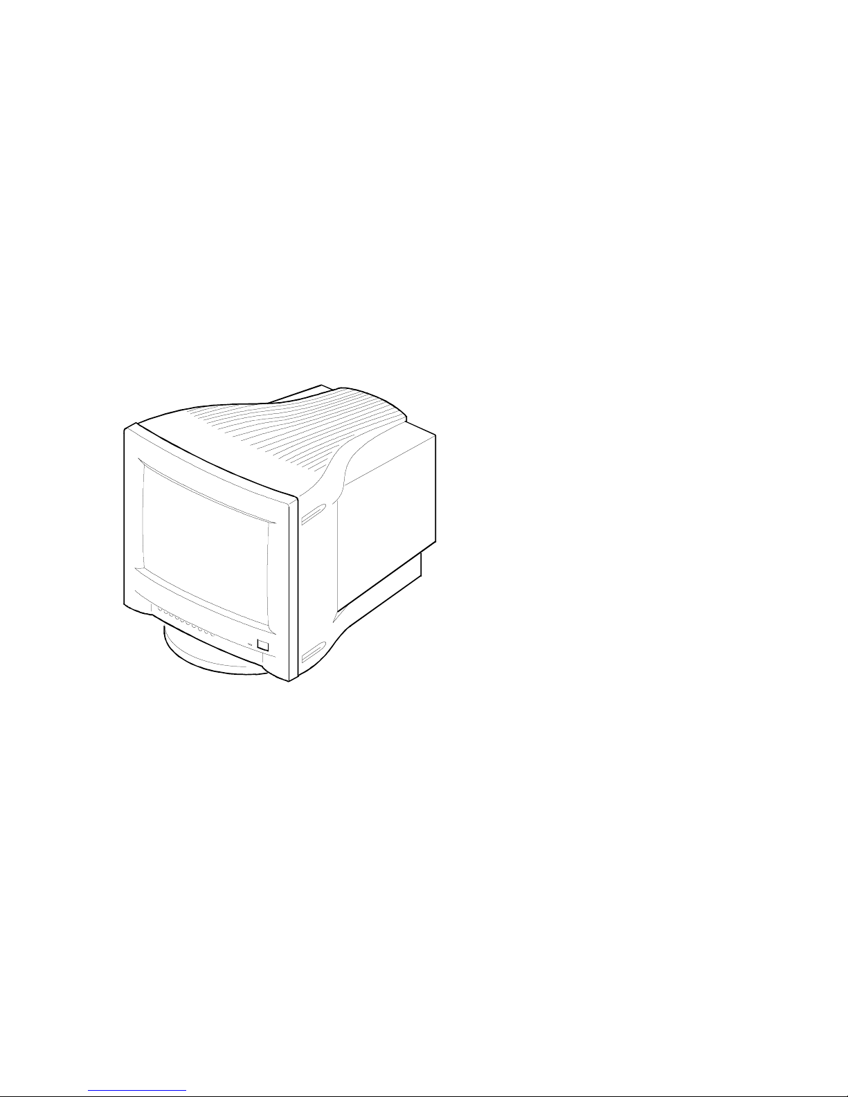
Introduction
Overview
The PCXBV-Ux Monitor is a 17-inch, 15.7 viewable,
multi-scanning
color
monitor with high resolution, compatible with VGA, SVGA, 1024 x 768, and
1280 x 1024 modes. The PCXBV-Ux offers the following features:
1280 x 1024 non-interlaced mode.
•
Power Management system that exceeds EPA ENERGY STAR™
•
requirements for saving energy.
VESA Data Display Channel - DDC1/2b
•
Complies with Swedish MPR2 standards for low emissions*
•
Complies with Swedish TCO ’92 standards even lower emissions**
•
Anti-glare screen with anti-static coating
•
DEC00800
Figure 1. PCXBV-Ux Color Monitor
*Models PCXBV-UA/UB/UC/UW/UX/UY.
**Models PCXBV-UD/UZ.
1
Page 6

DDC (Display Data Channel)
DDC is a communication channel over which the monitor automatically
informs the host system about its capabilities. DDC uses a formerly
unconnected signal pin in the 15-pin VGA connector. The system will perform
the “Plug ‘n Play” feature if both the monitor and the host implement DDC
protocol.
Installation
Installation/Operating Guidelines
Observe the following basic rules for installation and use.
Do . . .
Use the power cord supplied with the monitor, which is UL-, CSA-,
•
and VDE-approved.
Turn the monitor off when not being used for an extended period of
•
time, or use Power Management if applicable.
Do Not . . .
Overload the ac outlet.
•
Move the monitor on a stand over carpet or thresholds.
•
Push objects into the monitor’s openings.
•
Add accessories that are not designed for this monitor.
•
Operate the monitor near water or in a damp environment, which
•
could cause and electrical hazard.
Operate the monitor near magnets, motor devices, transformers,
•
high power lines, or large steel pillars, which can cause distortion in
the picture.
Obstruct the ventilation openings in the monitor’s cabinet, such as
•
placing the monitor on a rug or within an enclosure.
Place the monitor near a radiator or heat source.
•
2
Page 7

Monitor Installation
To connect your monitor:
1. Make sure the power to the monitor and the computer is off.
2. Connect the signal cable to the monitor then to the 15-pin interface
connector on the High Resolution Graphic Video Adapter on the
back of the computer.
3. Plug the ac power cord to the monitor, then to a properly-grounded
ac electrical outlet.
DEC00801
Figure 2. PCXBV-Ux Monitor (Rear View)
3
Page 8

Turn On Power to Monitor
Push the power switch button (3) to turn on the monitor. The power indicator
LED (2) should light green. For screen alignment, use the monitor controls (1).
1
23
DEC00802
Figure 3. Monitor Control Panel
4
Page 9

Monitor Adjustments
Figure 4 shows the monitor adjustment controls. Some of the controls (1) have
two functions. Press the button once or Function 1; press the button again for
Function 2. Tables 1 and 2 define these functions. The monitor saves your
settings four seconds after your last adjustment.
DEC00803
Figure 4. Monitor Controls
Table 1. User Controls and Functions
Icon Name Function
Brightness Adjusts black level for comfortable viewing.
Contrast Adjusts white level for comfortable viewing.
▼
▲
Decrease Decreases value for the selected control.
Increase Increases value for the selected control.
Recall Recalls factory default settings. See Caution.
Degauss Clears picture impurity caused by moving the
monitor to a new location. See Caution.
CAUTION: Pressing the Recall button, or pressing the
Degauss button for longer than 5 seconds, resets all of the
data in the user memory area so you must remake your user
adjustments.
5
Page 10

Table 2. User Controls Used With Arrow Buttons
Icon Name With Function 1 Function 2
COLOR
TEMP.
Position (H/V) Adjusts horizontal
position.
Position (H/V)
▼▲
Adjusts vertical
position.
Selects user or
preset modes.
Pages through list
of modes.
Size (H/V) Adjusts horizontal size.Displays
information on the
specifications.
Size (H/V)
▼▲
Adjusts vertical size. Pages through list
of specifications.
Geometric
distortion
Pincushion:
the sides from
bowing in or out.
Adjusts
Parallel:
the top and
bottom to be
parallel.
Geometric
distortion
▼▲
Trapezoid:
Adjusts
the top and bottom
Adjusts the
Tilt:
tilt of the display.
to be the same.
Color
temperature
▼▲
Adjusts temperature
between 9300° and
–
6500°K color.
Adjusts
6
Page 11

Servicing
Cleaning the Monitor
To clean the monitor:
1. Unplug the monitor.
2. Clean the monitor with a soft, slightly damp cloth. Do not use an
aerosol cleaner directly on the screen.
_____________________CAUTION __________________________
Do not use benzene, thinner, or any volatile substance to clean
the monitor, as these products may discolor the monitor’s
cabinet. Likewise, do not place rubber or vinyl on the monitor.
Maintenance and Troubleshooting
Identifying and Correcting Problems
The following can be sources of problems:
Communications cables
•
Host system
•
Nearby power or electrical sources
•
7
Page 12

Troubleshooting Table
Use Table 3 to identify and correct any problem area.
Table 3. Identifying and Correcting Problems
Symptom Possible Cause Suggested Solution
Display does not
appear.
Brightness or
contrast control is
set too low.
Power Management
feature is active in
the off state.
There is no power.
Color impurity Magnetic fields can
build up on the CRT.
Video display has
moving dots and
distorted lines.
The display rolls or
flickers.
CAUTION:
Degauss
There is
electromagnetic
interference.
Adjustments may be
out of alignment.
Pressing the
Recall
button for longer than 5 seconds, resets all of the
data in the user memory area so you must remake your user
adjustments.
Increase the brightness and
contrast control setting to suit
you.
Press any key and allow 20
seconds for monitor to warm
up.
Check the power cord. Use
another ac outlet.
Press the degauss switch to
demagnetize the CRT. See
Caution
below.
Move any electromagnetic
device, such as a fan or motor,
away from the monitor or move
the monitor.
Hold the Recall button until the
LED changes from green to
orange then back to green. See
Caution
below.
button, or pressing the
8
Page 13

Tilt/Swivel Stand Removal
To remove the stand, remove the screw that secures the bottom of the stand
and slide it back.
DEC00799
Figure 5. Tilt/Swivel Stand Removal
9
Page 14

Specifications
Scanning Modes
Table 4 Display Modes and Addressability
Mode Display
Mode
Addressability
Horizontal
Frequency
(KHz)
Vertical
Frequency
1 VGA 60 640 x 480 31.47 59.95
2 DOS 70 720 x 400 31.47 70.08
3 VGA/350 70 640 x 350 31.47 70.08
4 VGA
640 x 480 37.50 75.00
VESA 75
5 ErgoVGA
640 x 480 37.86 72.81
72
6 SVGA/60 800 x 600 37.88 60.32
7 SVGA
800 x 600 46.88 75.00
VESA 75
8 1024 x 768 1024 x 768 48.36 60.00
9 VESA 70 1024 x 768 56.48 70.07
10 1024 x 768
1024 x 768 60.02 75.03
VESA 75
11 1280 x 1024 1280 x 1024 64.98 60.10
(Hz)
H
SyncVSync
––
–+
+–
––
––
++
++
––
––
++
––
10
Page 15

Monitor Specifications
Table 5 Monitor Specifications
Monitor
43 cm (17-inch, 15.7 maximum viewable)
non-glare, non-static, multilayer optical coating
Active Area 32.0 x 24.0 cm (12.6 x 9.4 in)
Height 42.6 cm (16.8 in), includes tilt/swivel base
Width 43.4 cm (17.1 in)
Depth 44.4 cm (17.5 in)
Swivel
Tilt
±45°
-5° to +13
°
Weight 18 Kg (39.6 lb)
Video Signal
0.7V p-p R, G, B color; separate Sync (positive
or negative); 75
TTL
Horizontal
Scan Rate 30 - 65 kHz
Vertical Scan
Rate 50 - 120 Hz, non-interlaced
Connector 15-pin D-sub
Power input 100 - 240 Vac, 1.0 A. maximum, 50 - 60 Hz.
Environment
Operating
0° - 40°C
Temperature
Humidity 10 - 90% relative humidity (noncondensing)
11
Page 16

Power Management System
The monitor has three power-saving states indicated by the LED on the front
panel. A personal computer can control these states to reduce the monitor’s
output power levels while not in use, thus saving energy.
For proper operation of this Power Management System, make sure that the
monitor signal cable is connected to the host system and that the host is On.
Table 6 Power Saving States
LED State
Power Consumption
(Watts)*
Recovery
Time
Green (Normal) On 110 (max) n/a
Amber Standby < 75 3 s
Alternating
Suspend < 15 3 s
Amber/Green
Alternating
Off < 5 15 s
Amber/Off
*These power-saving states exceed the Environmental Protection Agency (EPA) Energy Star
requirements using the Video Electronics Standards Association (VESA) methodology for
Display Power Management Signals.
Environment
This monitor has been designed and manufactured to minimize the impact to
the environment.
Acoustic Levels
Preliminary declared values per ISO 9296 and ISO 7779:
Sound Power Level
B
L
Wad
1
Idle Operate Idle Operate
PCXBV-Ux N/A 3.2 N/A 25
1
1 B = 10 dBA
2
Operator position
Sound Pressure
2
Level
L
pAm
dBA
12
Page 17

Asbestos
This monitor does not use asbestos in any form.
Flame Retardants
The enclosures do not contain polybrominated diphenylether (PBDE) as a
flame retardant additive; therefore, they do not emit toxic dibenzofuran and
dibenzodioxin gases.
Ozone Depleting Substances (ODS)
These monitors are in full compliance with the labeling requirements in the
U.S. Clean Air Act Amendments of 1990. It does not contain, nor is it
manufactured with, a Class 1 ODS, as defined in Title VI section 611 of this
act.
PVC
The plastic enclosures are not made of rigid PVC. The material has a nonhalogenated, flame-retardant system and is cadmium free.
Recyclable Material
The packaging material can be recycled, or you can save it to return the
monitor to a service center for repair or disposal.
Monitor Disposal
____________________ WARNING__________________________
If you need to dispose of a monitor, ask a qualified service
representative for the proper procedure. Improper disposal
could result in personal injury from implosion.
VCCI Class 2
13
 Loading...