

Digital Equipment PBXGB–AA, PBXGB–CA Owner's Manual

PBXGB–AA/CAPCIGraphicsOption
Owner’sGuide
Order Number: EK–PCIGR–OG. A01
Digital Equipment Corporation
Maynard, Massachusetts

First Printing, December 1995
Digital Equipment Corporation makes no representations that the use of its
products in the manner described in this publication will not infringe on
existing or future patent rights, nor do the descriptions contained in this
publication imply the granting of licenses to make, use, or sell equipment or
software in accordance with the description.
© Digital Equipment Corporation 1995. All Rights Reserved.
Printed in U.S.A.
The following are trademarks of Digital Equipment Corporation: DEC,
Digital, Digital Open3D, Digital UNIX, OpenVMS, VAX DOCUMENT, and the
DIGITAL logo.
Microsoft is a registered trademark, and Windows NT is a trademark of
Microsoft Corporation.
All other trademarks and registered trademarks are the property of their
respective holders.
S3087
This document was prepared using VAX DOCUMENT Version 2.1.

FCC Notice:
FCC ID: AO9-PBXGC and AO9-PBXGD
This device complies with Part 15 of the FCC Rules. Operation
is subject to the following conditions:
1. This device may not cause harmful interference, and
2. This device must accept any interference received, including
interference that may cause undesired operation.
This equipment has been tested and found to comply with
the limits for a Class B digital device, pursuant to Part
15 of the FCC Rules. These limits are designed to provide
reasonable protection against harmful interference in a
residential installation. Any changes or modifications made
to this equipment may void the user’s authority to operate this
equipment.
This equipment generates, uses, and can radiate radio frequency
energy and, if not installed and used in accordance with
the instruction manual, may cause harmful interference to
radio communications. However, there is no guarantee that
interference will not occur in a particular installation. If this
equipment does cause harmful interference to radio or television
reception, which can be determined by turning the equipment off
and on, the user is encouraged to try to correct the interference
by one or more of the following measures:
• Reorient or relocate the receiving antenna.
• Increase the separation between the equipment and receiver.
• Connect the equipment into an outlet on a circuit different
from that to which the receiver is connected.
• Consult the dealer or an experienced radio/TV technician for
help.
The video cable port should be connected with only a shielded
data cable with an integrated ferrite bead over the cable. If
this port is connected with a cable without such a ferrite bead,
additional ferrite beads shall be clamped over the cable next to
the cable connector near the system unit.
iii
DOC
Compliance
Statement
This digital apparatus does not exceed the Class B limits for
radio noise emissions from digital apparatus set out in the
Radio Interference Regulations of the Canadian Department of
Communications.
MDC Avis De
Conformation
EMI
VCCI
Le present appareil numerique n’emet pas de bruits
radioelectriques depassant les limites applicables aux appareils
numeriques de Classe B prescrites dans le Reglement sur
le brouillage radioelectriques edicte par le ministere des
Communications du Canada.
This product complies with the following domestic and
international standards:
• Domestic: Complies with FCC Part 15, Class B.
• International: Complies with CISPR22 (EN5502 [European
Norm]) Class B.
iv

Contents
Guide Overview . ........................................... 1
Purpose ............................................... 1
Contents............................................... 1
Conventions . ........................................... 2
Module Overview ........................................... 3
Description . . ........................................... 3
Version Information . . . ................................... 3
Software ............................................... 4
Limitations . ........................................... 4
Option Features ......................................... 5
Frequency Switch ........................................... 7
Description . . ........................................... 7
Switch Settings ......................................... 7
Module Installation ......................................... 9
Procedure . . . ........................................... 9
Confirming Proper Installation ................................ 15
Procedure . . . ........................................... 15
Troubleshooting ......................................... 15
Stereo Viewing . . ........................................... 16
Description . . ........................................... 16
Stereo Cable . ........................................... 16
Stereo Monitor .......................................... 16
AppendixA—Video Timing .................................. 17
Appendix B — Module Specifications . ........................... 20
Physical Specifications . ................................... 20
Environmental Specifications ............................... 20
Power Consumption . . . ................................... 20
Video Output Characteristics ............................... 21
Stereo Output Characteristics . . . ........................... 21
Appendix C — Cabling Information . . ........................... 22
Cable Information ....................................... 22
Appendix D — For Digital Service Use .......................... 23
Introduction . ........................................... 23
v

FRU/Order Numbers ..................................... 23
Index
Figures
1 PBXGB–AA Graphics Option Module. . . ................ 5
2 PBXGB–CA Graphics Option Module. . . ................ 6
3 VGA Enable/Disable Settings—2 MB Module ............ 11
4 VGA Enable/Disable Settings—16 MB Module ........... 11
5 Installation of 2 MB Module . ........................ 12
6 Installation of 16 MB Module ........................ 13
Tables
1 Module Versions . . . ................................ 3
2 Compatible Software Versions ........................ 4
3 PBXGB–AA Module Features ........................ 5
4 PBXGB–CA Module Features ........................ 6
5 Switch Settings . . . ................................ 8
6 VGA Enable/Disable and Alias Jumper Settings . . . ....... 10
7 Video Monitor Timing I ............................. 18
8 Video Monitor Timing II............................. 19
9 PBXGB–AA/CA PCI Graphics Option Module Weight and
Dimensions ...................................... 20
10 PBXGB–AA/CA PCI Graphics Option Module Environmental
Specifications ..................................... 20
11 Video D-Sub Connector Pinout ........................ 21
12 Stereo Output Characteristics ........................ 21
13 Cable Options .................................... 22
14 Module FRUs ..................................... 23
vi

Guide Overview
Guide Overview
Purpose
Contents
This guide provides general information on the
PBXGB–AA/CA graphics option modules. This information is
independent of the hardware platform. For specific information
regarding your hardware platform, refer to your system
documentation.
The components on the PBXGB–AA/CA graphics option modules
are Energy Star ready.
The following information is included in this guide:
• Module description
• Module installation
• Confirming proper installation
• Stereoscopic viewing
• Video timing—frequency switch settings
• Module specifications
• Cabling information
• Field replaceable unit (FRU) order numbers
1

Guide Overview
Conventions
The following conventions are used in this guide:
CAUTION Cautions provide information to prevent
damage to equipment or software. Read
these carefully.
Important Important notations provide information to
allow your system to work properly.
Note Notes contain additional information that
you should be aware of.
2

Module Overview
Module Overview
Description
Version
Information
The PBXGB–AA/CA graphics option modules are PCI local bus
options that generate high-resolution, 2- and 3-dimensional
color graphics. Application programs can utilize these graphics
to render mechanical and electrical CAD, molecular modeling,
scientific visualization, simulation, animation, and other
graphical information.
Table 1 provides information about this version of the
PBXGB–AA/CA graphics option modules.
Table 1 Module Versions
Order Number Planes Memory
PBXGB–AA 8 2 MB
PBXGB–CA 24Z 16 MB
Each order includes the following items:
• PBXGB–xx Option Module
• PBXGB–AA/CA PCI Graphics Option Owner’s Guide
• Graphics Support Services Software Version 3.0 for Microsoft
Windows NT Installation and User Guide
• Antistatic wriststrap
• Ferrite bead assembly
3

Module Overview
Software
Limitations
The PBXGB–AA/CA graphics option modules are compatible
with the minimum software version levels shown in Table 2.
Table 2 Compatible Software Versions
Designation
PBXGB–AA V3.2 V3.2c V6.2 V3.51 V3.0
PBXGB–CA V3.2 V3.2c V6.2 V3.51 V3.0
Digital
Open3D
Digital
UNIX
OpenVMS
Alpha
Microsoft
Windows
NT
Graphics
Support
Services
Software
The configuration of a multihead system requires operating
system support. Refer to your operating system documentation,
the Graphics Support Services Software Version 3.0 for Microsoft
Windows NT Installation and User Guide, and the Digital
Open3D software release notes, for information.
In a multihead system, only one graphics module can have VGA
enabled.
4
Module Overview
Option
Features
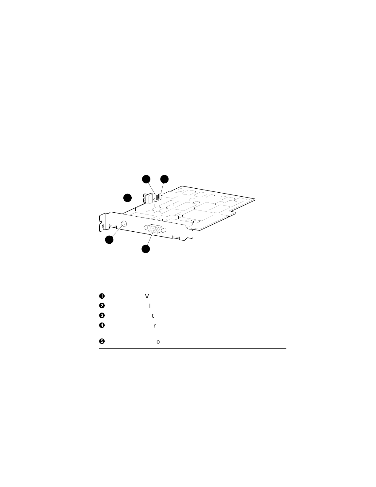
The PBXGB–AA graphics option module is shown in Figure 1.
Table 3 describes the features.
Figure 1 PBXGB–AA Graphics Option Module
2
3
4
5
1
MLO-011732
Table 3 PBXGB–AA Module Features
Reference
Number Description
!
"
#
$
%
VGA enable/disable jumper pins
Alias jumper pins
Rotary video selection frequency switch
Stereoscopic cable port, 3.5 mm (0.18 in.) audio jack
connector
Video cable port, 15-pin D-sub connector
5
 Loading...