

Digital Equipment ML200-AA, ML200 Series, ML200-CA, ML200-BA Installation Manual

dt
ML200 PCI NVRAM Installation Information
EK–ML200–IN. A01
October 1994
Introduction
The ML200 PCI NVRAM module is a nonvolatile disk write cache used to
accelerate file servers that use NFS, a synchronous disk I/O protocol. The ML200
module may be installed in any full-size 5 V 32-bit PCI slot. The ML200 is
available in three options: ML200-AA (2 MB), ML200-BA (4 MB), and ML200-CA
(8 MB).
Installation Procedure
Use the following procedure to install the ML200 PCI NVRAM module in an
Alpha AXP system:
1. Before installing the ML200 PCI NVRAM module, contact your service
representative to verify that the installed versions of OSF/1 and console code
support the ML200 module. If they do not support the ML200 module, a
system software upgrade is required before proceeding.
2. Refer to the system documentation to identifya5V32-bit PCI slot location
and module orientation for installing the ML200 PCI NVRAM module.
3. Install the Prestoserve license product authorization key (PAK) by referring to
the DEC OSF Guide to Prestoserve documentation. Follow these instructions
for reconfiguring the system with the Prestoserve driver enabled.
4. Perform an orderly powerdown of the system.
5. Remove the ML200 PCI NVRAM module from the shipping container.
6. Remove the Mylar insulator located between the battery and the + battery
terminal clip (see Figure 1). Do not place the module on a metal or conductive
surface. Doing so could discharge or damage the battery.
7. Remove any system covers, if necessary, to allow access to the PCI slots.
© Digital Equipment Corporation 1994. All Rights Reserved.
S2711
1
8. Remove the blank filler panel from the slot selected for installing the ML200
PCI NVRAM module. (Save the filler panel screw for securing the ML200
module in place.)
9. Slide the module into the selected slot and apply firm pressure until the
module is firmly seated. Secure the module in place with the screw that was
saved from the filler panel removal.
10. Replace all system covers, then reboot the system and verify that the ML200
PCI NVRAM is recognized by the system.
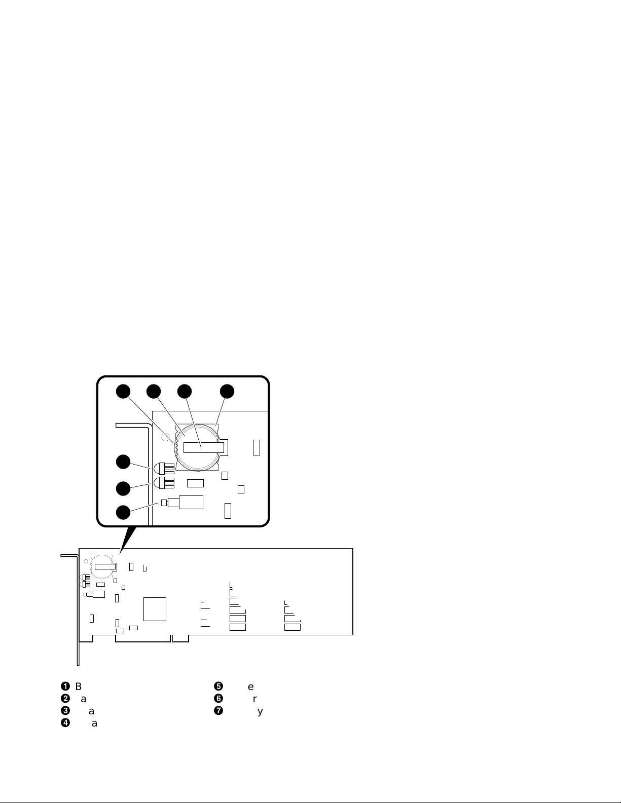
Figure 1 ML200 PCI NVRAM Module Battery, LEDs, and Test Switch
1 2 3 4
5
6
7
!
Battery holder
"
Battery
#
+ battery terminal clip
$
Mylar insulator
2
%
Battery charged LED
&
Battery enabled LED
'
Battery enabled test switch
MA00118
 Loading...