

Digital Equipment MicroVAX II 630QB Owner's Manual

.
..:
.'
:.....
. :::..
......
+ + + + + + + +
.
.......
.
JCJCIC":::::::-:::-:
JC1CJC:::::::-:::-:-:
.
'.'
.'
'.'
:....
.:
'.'
.:.:':
.:.'
:."
+ + + + + + + +
. ..
.....
..
. .
JCJCICIC:::::::
e
:::-:
JC1C1C:::::::-:::-:-:
.....
:..
'.'
..
'':.
..... + + + + + + + +
.
..
JCJCIC":::::::-:::-:
JC1C1C:::::::-:::-:-:

AZ-FNBAA-MN
· . .'. .
.... : ...
:.:.:::.:::
:.:: : :.:
:.:.:-:
:.:.:.:.:-:.:-:
.:-:.:-:
::-:::::::-::::::::::::::::::+:+:+:+.:..
+ + +
• • •
•••••••••••••••••••••
•• ••
• •
••••••
••••••••••••
0
.0
•••••
••
· .
.'.
. .
... : ...
:.:.:::.:::
:.:: : :.:
:.:.:-:
:.:.:.:.:-:.:-:.:-:.:-:::-:::::::-::::::::::::::::::+:+:+:+.:..
+ + +
•
•••••••••••••••••••••••••••
• •
•••
•••••••••••••••
0
••••••••
•
· . .
'. . .... : ...
:.:.:::
.::: :.:::
:.:
:.:.:-:
:.:.:.:.:-:
.:-:.:-:
.:-:::-:::::::-::::::::::::::::::+:+:+:+.:..
+ + +
· . .
......................
..
.............................. .
MicroVAX
II
630QB
Owner's
Manual
~
xx:::::::·:::
X
••••••••••••
t
•
•••••••••
I
~
xx:::::::·:::
X
•••••••••••••
••••••••••
I
~
xx:::::::·:::
X
••••••••••••·
•
•••••••••
I
Prepared
by
Corporate
User
Publications
of
Digital Equipment Corporation

First
Printing,
October 1985
Second
Printing,
December 1985
Updated, May 1986
The
information
in
this
document is subject to change
without
notice
and
should not be construed
as a commitment
by
Digital
Equipment
Corporation.
Digital
Equipment
Corporation
assumes
no responsibility for
any
errors
that
may
appear
in
this
document.
The
software described
in
this
document is furnished
under
a license
and
may
only be
used
or copied
in
accordance
with
the
terms
of such license.
No responsibility is
assumed
for
the
use or
reliability
of software on
equipment
that
is not supplied by DIGITAL
or
its
affiliated companies.
©
Digital
Equipment
Corporation 1985, 1986.
All
Rights
Reserved.
Printed
in
U.S.A.
A postage-paid READER'S COMMENTS form is included on
the
last
page of
this
document. Your comments will
assist
us
in
preparing
future
documentation.
The
following
are
trademarks
of
Digital
Equipment
Corporation:
COMPACTape
DECmate
DECsystem-10
DECSYSTEM-20
DECUS
DECwriter
DIBOL
FALCON
LSI-ll
~amaDmaTM
MASSBUS
MicroPowerlPascal
MicroVAX
MicroVMS
MicroPDP-11
PDP
P/OX
Q-BUS
Professional
Rainbow
RSTS
RSX
ULTRIX-32m
UNIBUS
VAX
VAXELN
VMS
VT
Work Processor
Notice
This
equipment
generates,
uses
and
may
emit
radio frequency energy.
The
equipment
has
been
tested
and
found
to
comply
with
the
limits
for a Class A
computing
device
pursuant
to
Subpart
J of
Part
15 of FCC Rules, which
are
designed
to
provide
reasonable
protection
against
such
radio
frequency
i.nterference
when
operated
in
a commercial
environment.
Operation
of
this
equipment
in a residential
area
may
cause
interference,
in
which case
the
user,
at
his
or
her
own expense,
may
be
required
to
take
measures
to
correct
the
interference.
iii

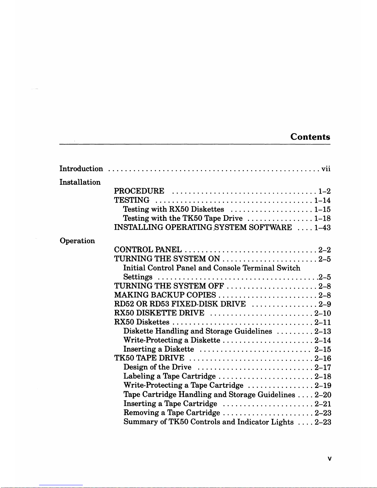
Contents
Introduction
...................................................
vii
Installation
PROCEDURE
...................................
1-2
TESTING
......................................
1-14
Testing
with
RX50 Diskettes
....................
1-15
Testing
with
the
TK50 Tape Drive
................
1-18
INSTALLING OPERATING .SYSTEM SOFTWARE
....
1-43
Operation
CONTROL PANEL
................................
2-2
TURNING THE SYSTEM ON
.......................
2-5
Initial
Control
Panel
and
Console Terminal Switch
Settings
.......................................
2-5
TURNING THE SYSTEM OFF
......................
2-8
MAKING BACKUP COPIES
........................
2-8
RD52 OR RD53 FIXED-DISK DRIVE
................
2-9
RX50 DISKETTE DRIVE
.........................
2-10
RX50 Diskettes
..................................
2-11
Diskette Handling
and
Storage Guidelines
.........
2-13
Write-Protecting a Diskette
......................
2-14
Inserting
a Diskette
...........................
2-15
TK50 TAPE DRIVE
..............................
2-16
Design of
the
Drive
............................
2-17
Labeling a Tape Cartridge
.......................
2-18
Write-Protecting a Tape Cartridge
................
2-19
Tape Cartridge Handling
and
Storage Guidelines
....
2-20
Inserting
a Tape Cartridge
......................
2-21
Removing a Tape Cartridge
......................
2-23
Summary
of TK50 Controls
and
Indicator Lights
....
2-23
v

Contents
Troubleshooting
POWER-ON MESSAGES
...........................
3-2
CORRECTIVE ACTIONS
..........................
3-4
THE
MICROVAX
MAINTENANCE SYSTEM
.........
3-11
Main Menu
...................................
3-13
Main Menu Options
............................
3-14
Upgrade
......................................................
4-1
Appendix A Related Documentation
............................
A-1
Appendix B Micro
VAX
II Specifications
PREPARING FOR
YOUR
MICROVAX
II SYSTEM
.....
B-1
Electrical Requirements
.........................
B-4
Environmental Requirements
....................
B-5
Acoustic Noise Emission
........................
B-6
System
Unit
Physical Specifications
...............
B-7
RX50 DUAL-DISKETTE DRIVE
....................
B-8
TK50 MAGNETIC TAPE
..........................
B-9
RD52 FIXED WINCHESTER DISK DRIVE
..........
B-10
RD53 FIXED WINCHESTER DISK DRIVE
..........
B-11
Appendix C Micro
VAX
II
Options
TERMINAL AND PRINTER OPTIONS
..............
C-1
MEMORY OPTIONS
..............................
C-2
COMMUNICATION OPTIONS
.....................
C-3
Glossary
vi
Introduction
This
manual
describes how to install
and
operate
the
MicroVAX II system
and
what
to
do
if
you have a problem with
the
system. Coverage is pro-
vided for
the
630QB (BA123-A) version. DIGITAL recommends
that
you
carefully read
the
Installation
and
Operation sections of
this
manual
before
you
attempt
to install
and
operate
the
Micro
VAX
II system.
This
manual
is for a Micro
VAX
II system user; little or no previous com-
puter
experience is assumed.
To
help nontechnical users, a glossary
explains common computer terms.
Detailed technical information is available
in
the
MicroVAX 11630QB
Technical Manual
and
in
other related documents. Related documents
and
their
order numbers
are
listed
in
Appendix
A.
vii

Installation
1
Before
installing
your system,
make
sure
the
site conforms to
the
environ-
mental
and
safety requirements summarized
in
Appendix B
in
this
manual.
If
you prefer
not
to
install
the
system yourself, DIGITAL provides
an
instal-
lation
service.
To
install
the
system, perform
the
following steps
in
order.
If
you
have
trouble, refer to
the
Troubleshooting section
that
begins on page
3-1.
1-1
Installation
PROCEDURE
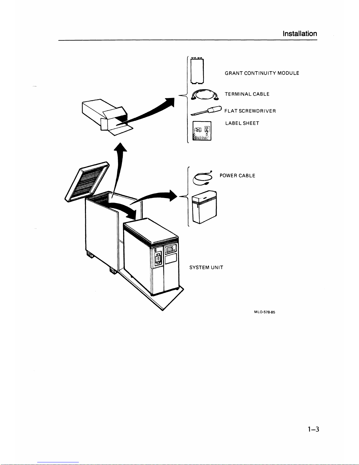
1 UNPACK THE
MICROVAX
II
SYSTEM.
If
any
item
is
missing or damaged:
• Contact your sales
representative
or store .
• Contact
your
delivery agent.
1-2
Installation
GRANT
CONTINUITY
MODULE
TERMINAL
CABLE
~
FLAT
SCREWDRIVER
LABEL
SHEET
POWER
CABLE
SYSTEM
UNIT
MLO-578-85
1-3
Installation
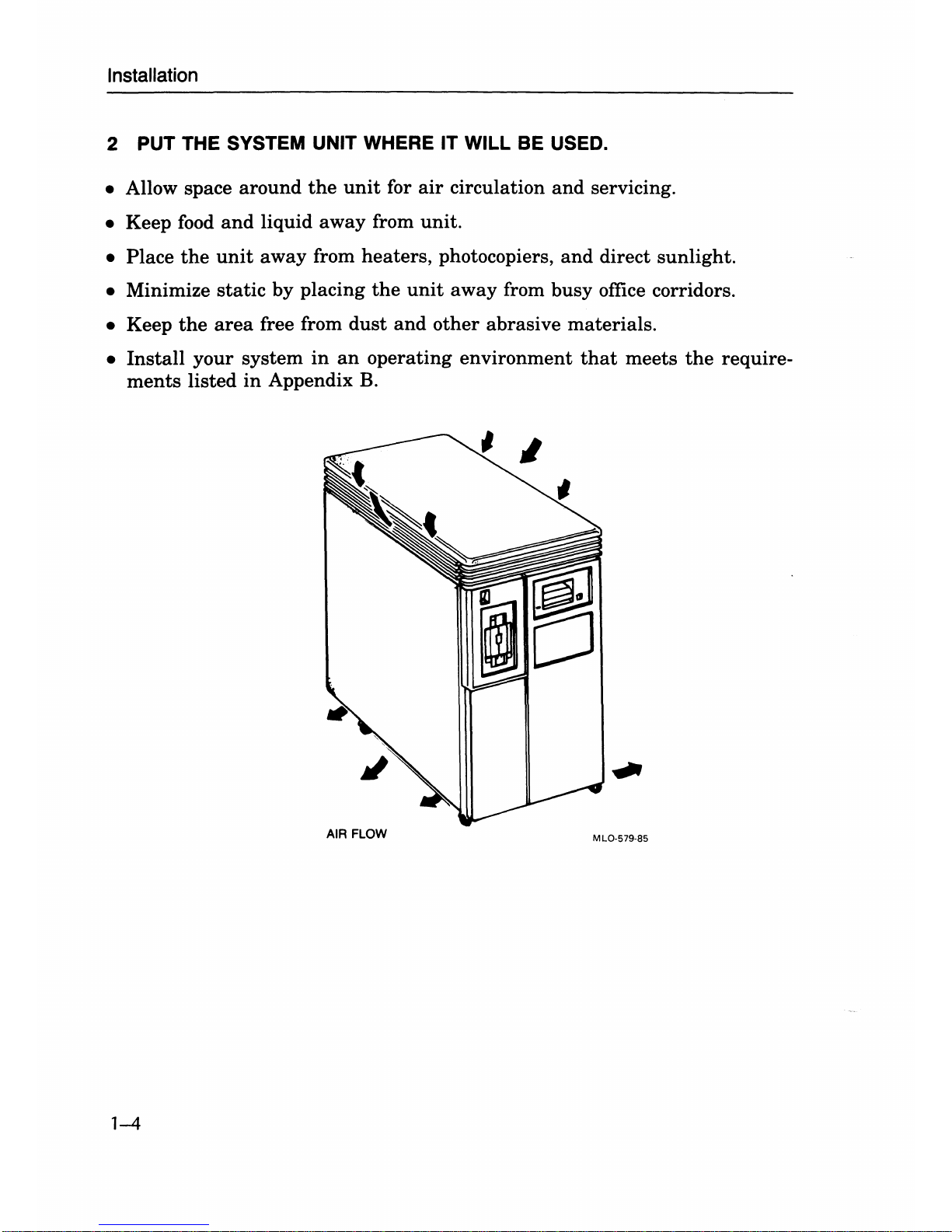
2 PUT THE SYSTEM UNIT WHERE IT WILL
BE
USED.
• Allow space
around
the
unit
for
air
circulation
and
servicing.
• Keep food
and
liquid
away
from
unit.
•
Place
the
unit
away
from
heaters,
photocopiers,
and
direct
sunlight.
• Minimize
static
by
placing
the
unit
away
from
busy
office corridors.
• Keep
the
area
free from
dust
and
other
abrasive
materials.
•
Install
your
system
in
an
operating
environment
that
meets
the
require-
ments
listed
in
Appendix
B.
AIR FLOW
MLO-579-85
1-4
Installation
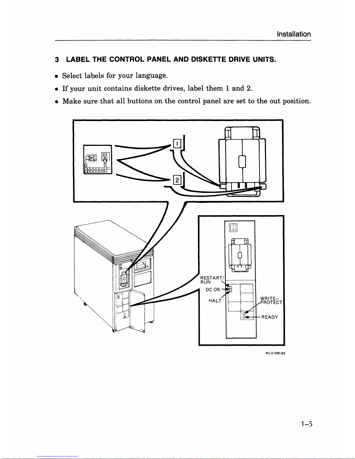
3 LABEL THE CONTROL PANEL AND DISKETTE DRIVE UNITS.
• Select labels for
your
language.
•
If
your
unit
contains
diskette
drives, label
them 1 and
2.
•
Make
sure
that
all
buttons
on
the
control
panel
are
set
to
the
out
position.
m
m
<
DCOK
-~
I-----
/'
HALT
L
~
V
-
WRITEPROTECT
READY
MLO-580-85
1-5
Installation
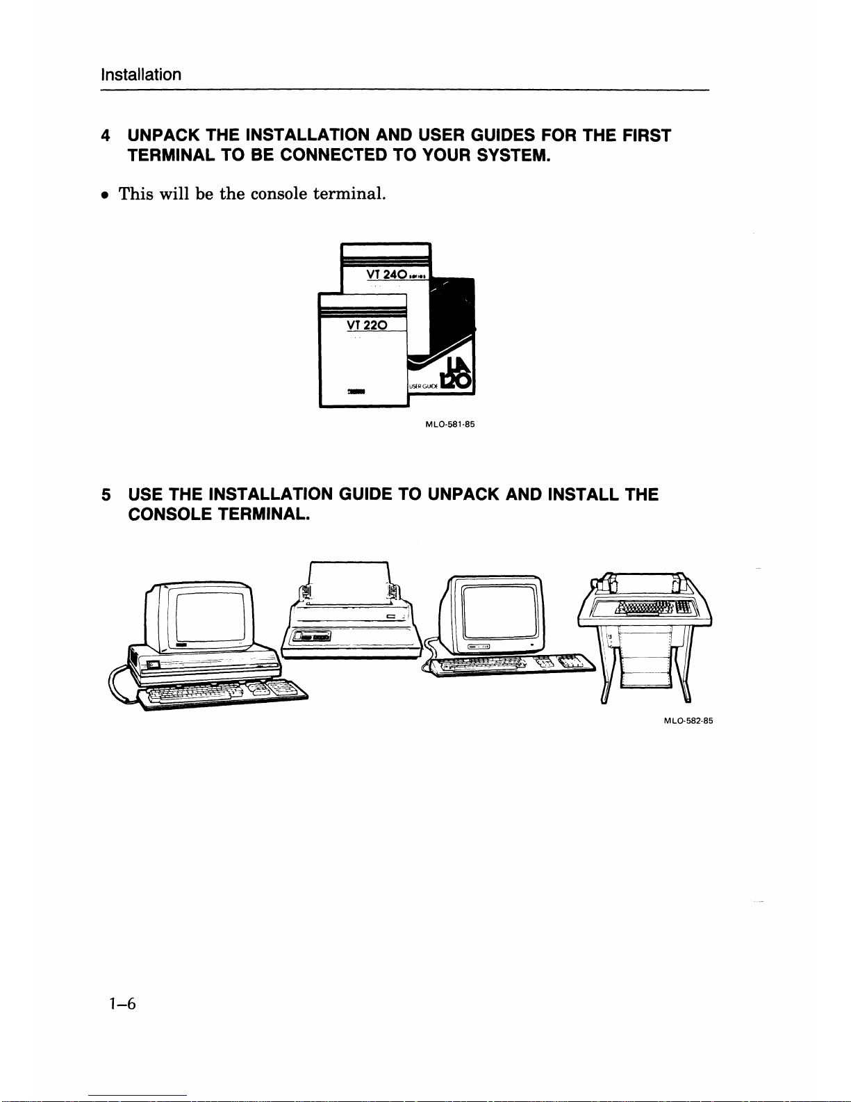
4 UNPACK THE INSTALLATION AND USER GUIDES FOR THE FIRST
TERMINAL TO BE CONNECTED TO YOUR SYSTEM.
•
This
will
be
the
console
terminal.
MLO·S8l·8S
5 USE THE INSTALLATION GUIDE TO UNPACK AND INSTALL THE
CONSOLE TERMINAL.
1-6
MLO-S82·8S
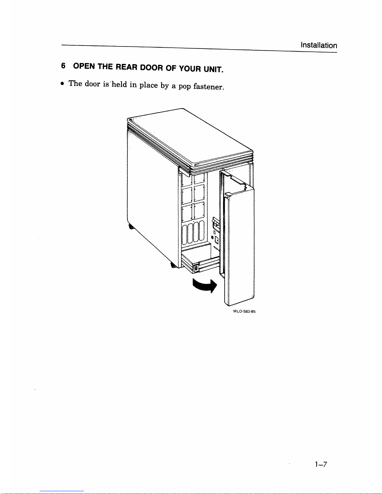
6 OPEN THE REAR DOOR OF
YOUR
UNIT.
•
The
door
is
'held
in
place by a pop fastener.
MLO·583·85
Installation
1-7
Installation
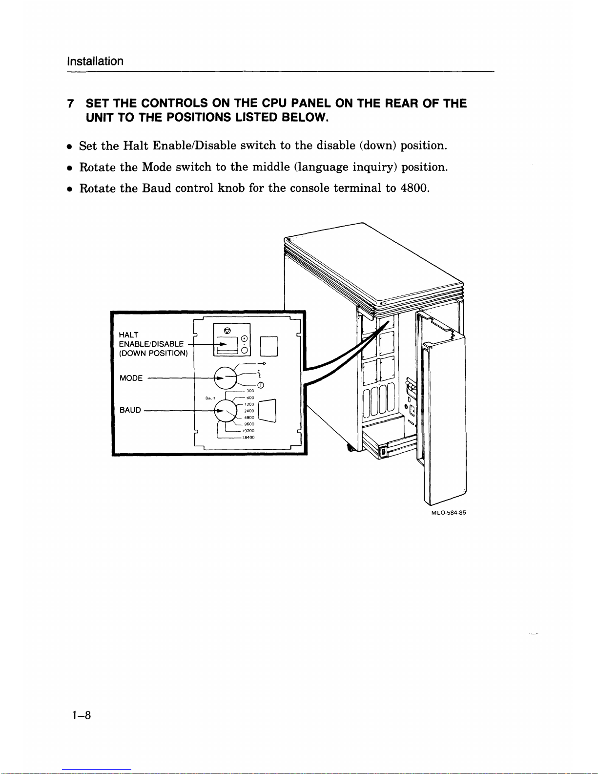
7 SET THE CONTROLS
ON
THE CPU PANEL
ON
THE REAR OF THE
UNIT TO THE POSITIONS LISTED BELOW.
•
Set
the
Halt
EnablelDisable switch to
the
disable (down) position.
• Rotate
the
Mode switch to
the
middle (language inquiry) position.
• Rotate
the
Baud
control knob for
the
console
terminal
to 4800.
HALT
ENABLE/DISABLE -+---tt-
(DOWN POSITION)
MODE------r-~_.
BAUD
------+--t-
MLO-5B4-B5
1-8
Installation
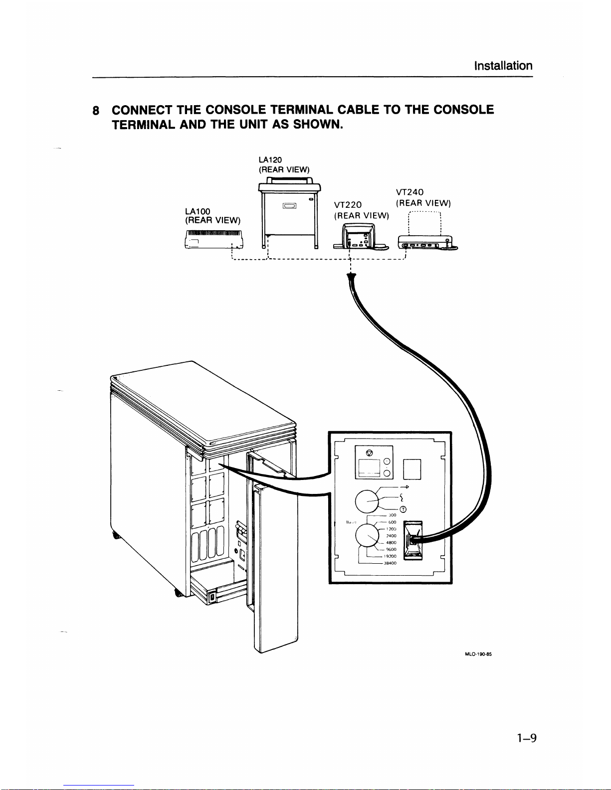
8 CONNECT THE CONSOLE TERMINAL CABLE TO THE CONSOLE
TERMINAL
AND THE UNIT
AS
SHOWN.
LA120
(REAR VIEW)
~
VT240
LA100
[Q]
0
VT220
(RE~~"~"IEW)
(REAR VIEW) (REAR VIEW)
:'
":
c~·'miOO.III.i:i::J:
a
~j
Yb
~.
_______
J
_________________
~---
___
____
)
,
rno
~r
""g--'~::
!:~~
hta;;liiiii~
_%00
\9200
J8400
MlO·190-85
1-9
Installation
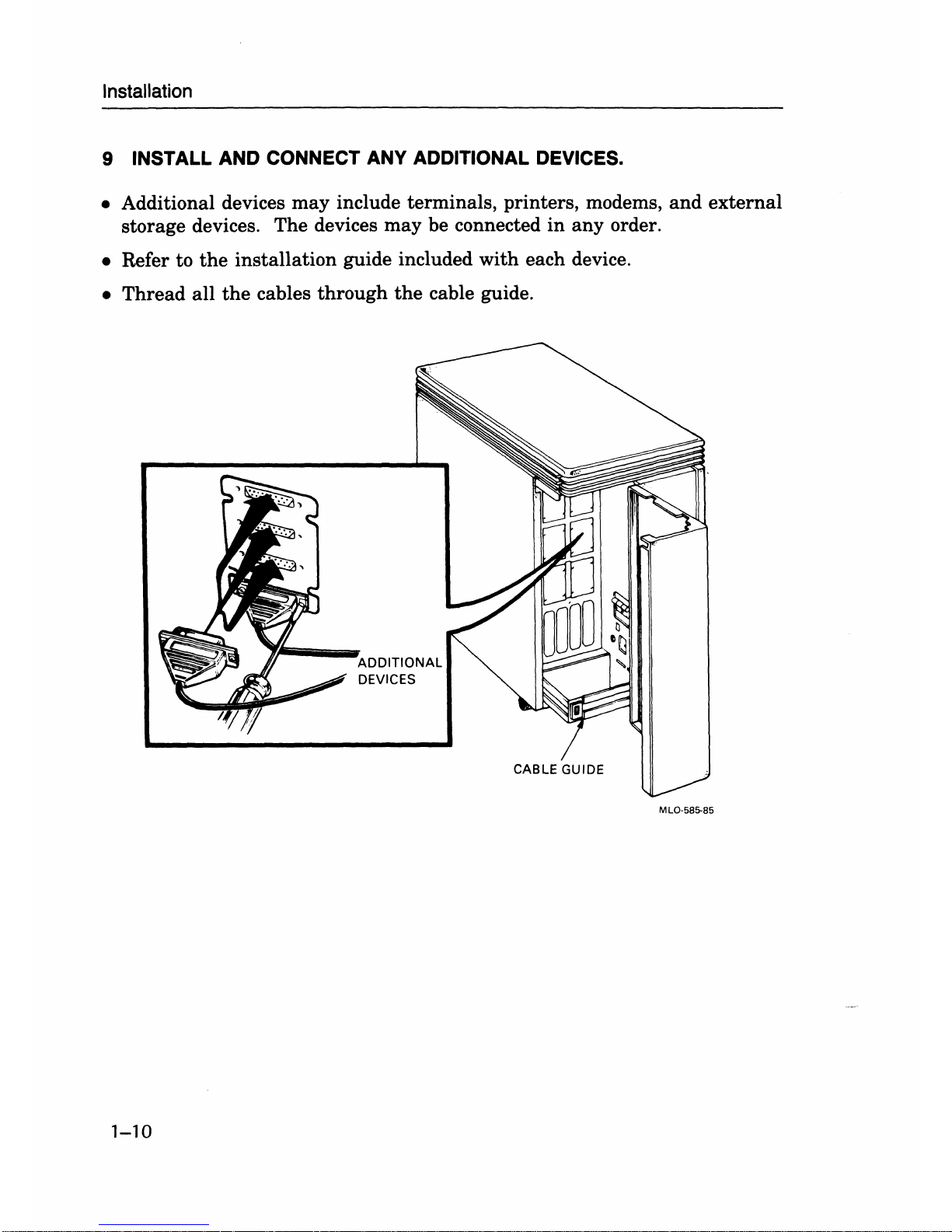
9 INSTALL
AND
CONNECT ANY ADDITIONAL DEVICES.
• Additional devices
may
include terminals, printers, modems,
and
external
storage devices. The devices may be connected
in
any
order.
• Refer to
the
installation guide included with each device.
•
Thread
all
the
cables
through
the
cable guide.
1-10
ADDITIONAL
DEVICES
CABLE GUIDE
MLQ-5B5-B5
Installation
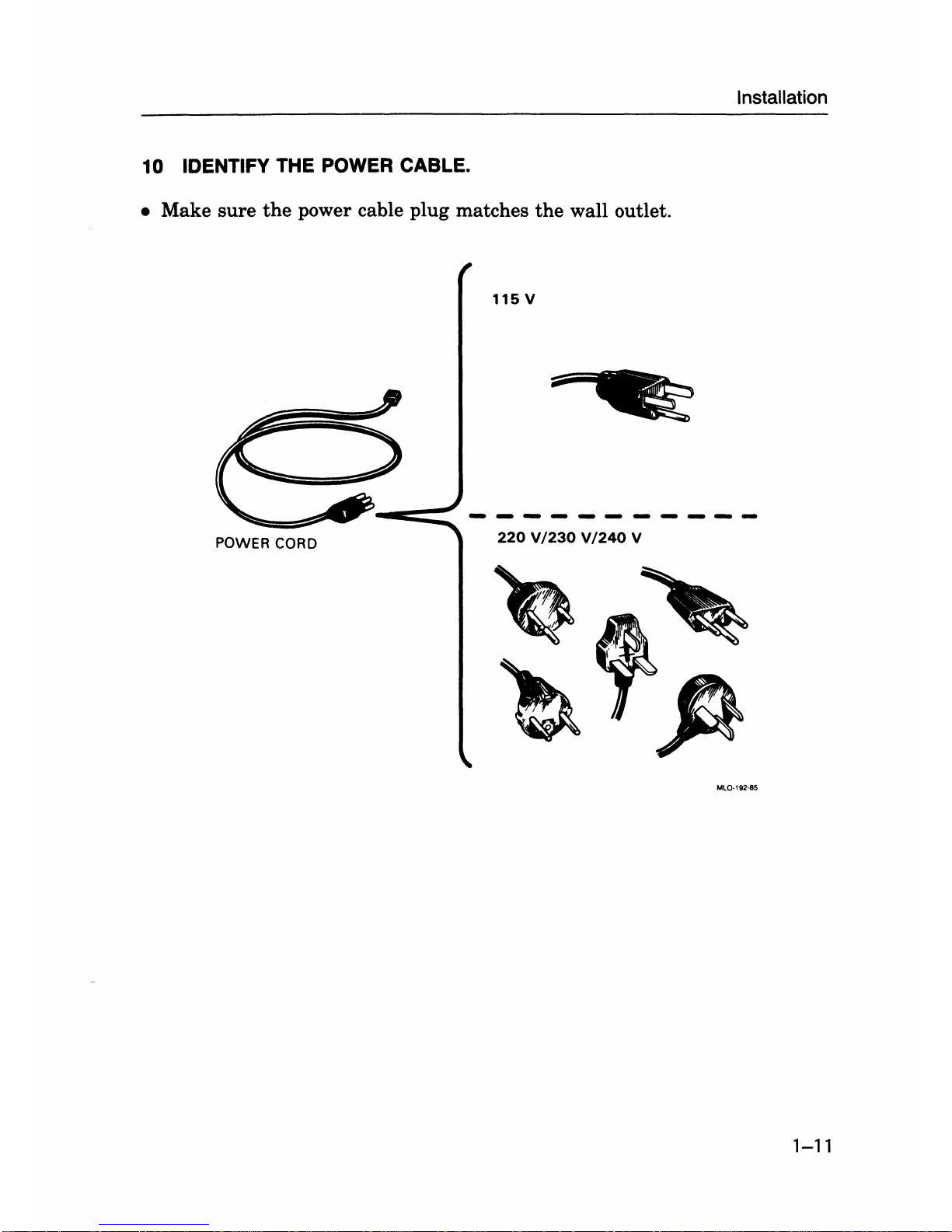
10 IDENTIFY THE POWER CABLE.
•
Make
sure
the
power cable
plug
matches
the
wall outlet.
115
V
POWER CORD
220
V/230 V/240
V
MLO·192·85
1-11
Installation
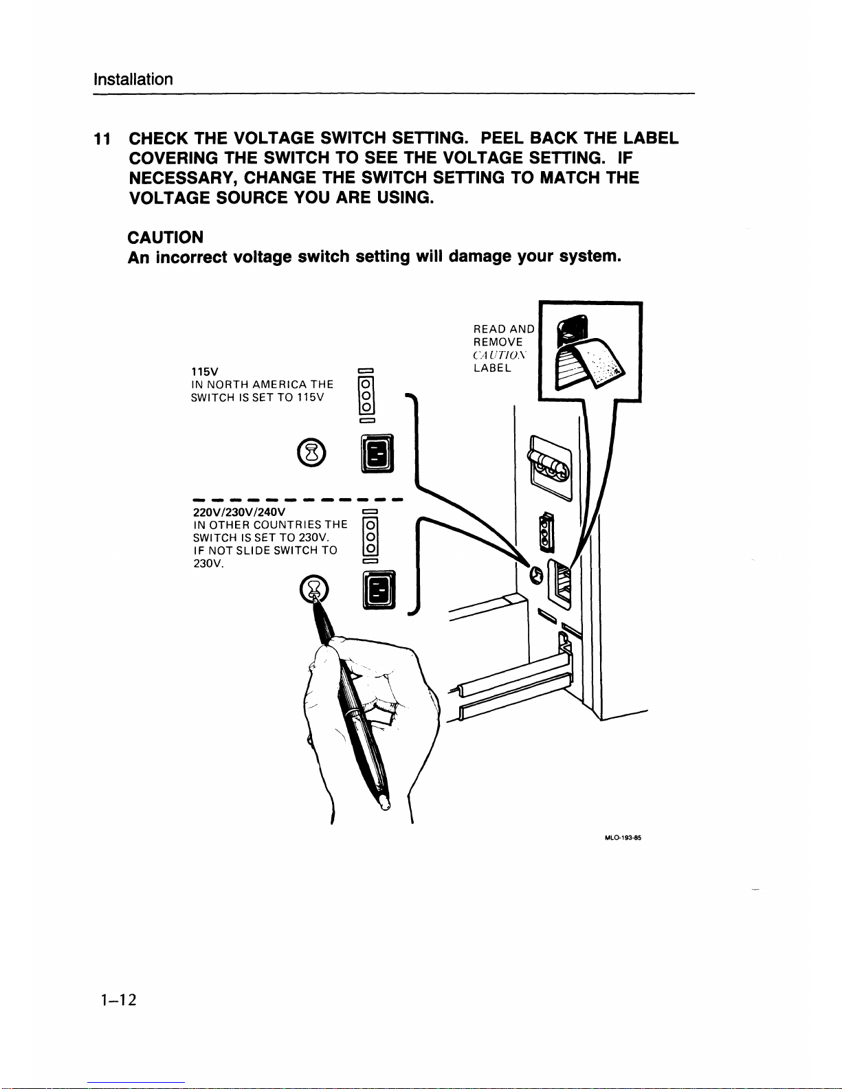
11
CHECK THE VOLTAGE SWITCH SETTING. PEEL BACK THE LABEL
COVERING THE SWITCH TO SEE THE VOLTAGE SETTING. IF
NECESSARY, CHANGE THE SWITCH SETTING TO MATCH THE
VOLTAGE SOURCE YOU ARE USING.
CAUTION
An incorrect voltage switch setting will damage your system .
1-12
115V
IN NORTH
AMERICA
THE
SWITCH
IS
SET TO 115V
@
II
220V
/230V
/240V
=>
IN OTHER COUNTRIES THE
~g
SWITCH
IS
SET TO 230V.
IF NOT
SLIDE SWITCH TO
230V.
=>
II
READ
AND
REMOVE
CAUT/D.\
LABEL
..
~
""
- "
.••••
lOo;
~',
.
ML0-193-85
Installation
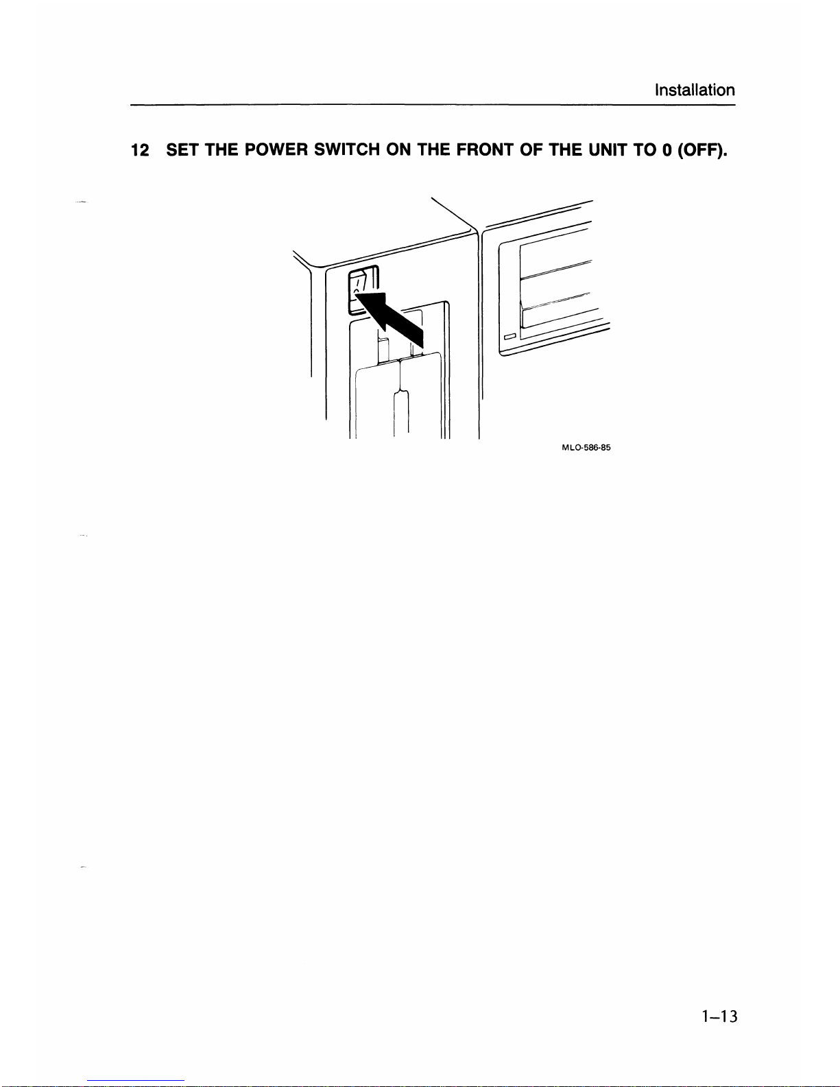
12 SET THE POWER SWITCH
ON
THE FRONT OF THE UNIT TO 0 (OFF).
MLO-5B6-85
1-13
Installation
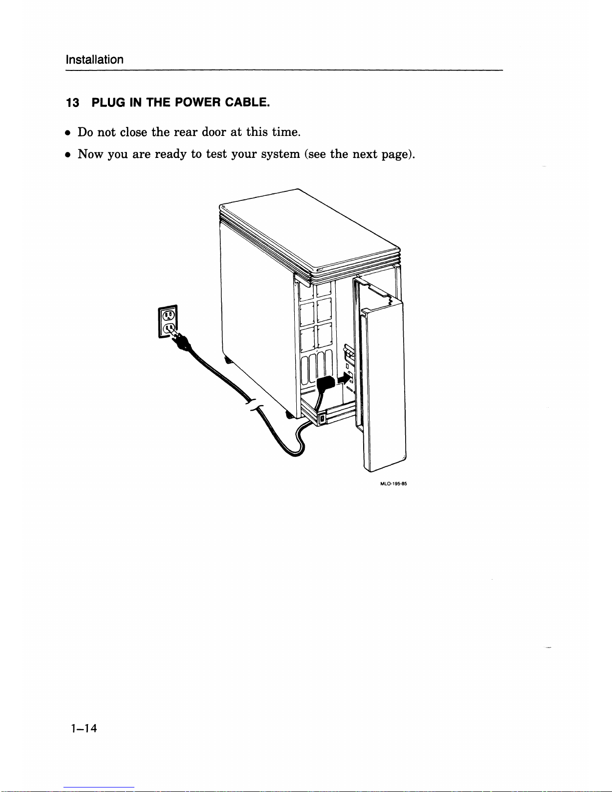
13
PLUG
IN
THE POWER CABLE.
•
Do
not
close
the
rear
door
at
this
time .
• Now you
are
ready to
test
your system (see
the
next page).
MlO-195-85
1-14
Installation
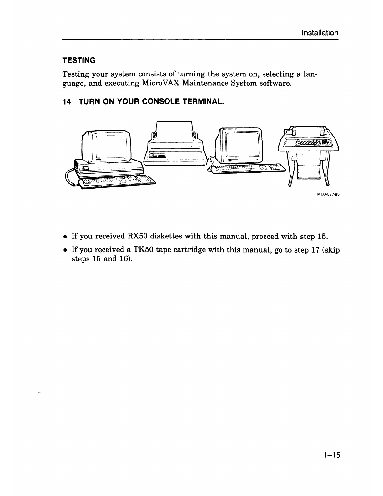
TESTING
Testing your system consists of
turning
the
system on, selecting a lan-
guage,
and
executing Micro
VAX
Maintenance System software.
14 TURN
ON
YOUR CONSOLE TERMINAL.
MLO-587·85
•
If
you received RX50 diskettes
with
this
manual,
proceed
with
step 15.
•
If
you received a TK50
tape
cartridge
with
this
manual,
go
to
step 17 (skip
steps 15
and
16).
1-15
Installation
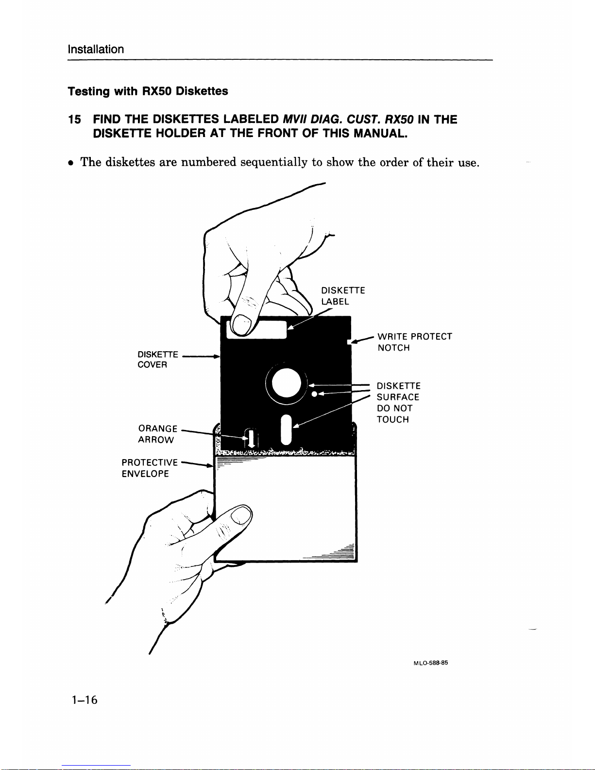
Testing with RX50 Diskettes
15
FIND THE DISKETTES LABELED MVII D/AG. CUST. RX50 IN THE
DISKETTE HOLDER AT THE FRONT OF THIS MANUAL.
• The diskettes
are
numbered sequentially to show
the
order of
their
use.
1-16
DISKETTE
__
+
COVER
PROTECTIVE
ENVELOPE
WRITE
PROTECT
NOTCH
DISKETTE
SURFACE
DO
NOT
TOUCH
ML()'581!-85
Installation
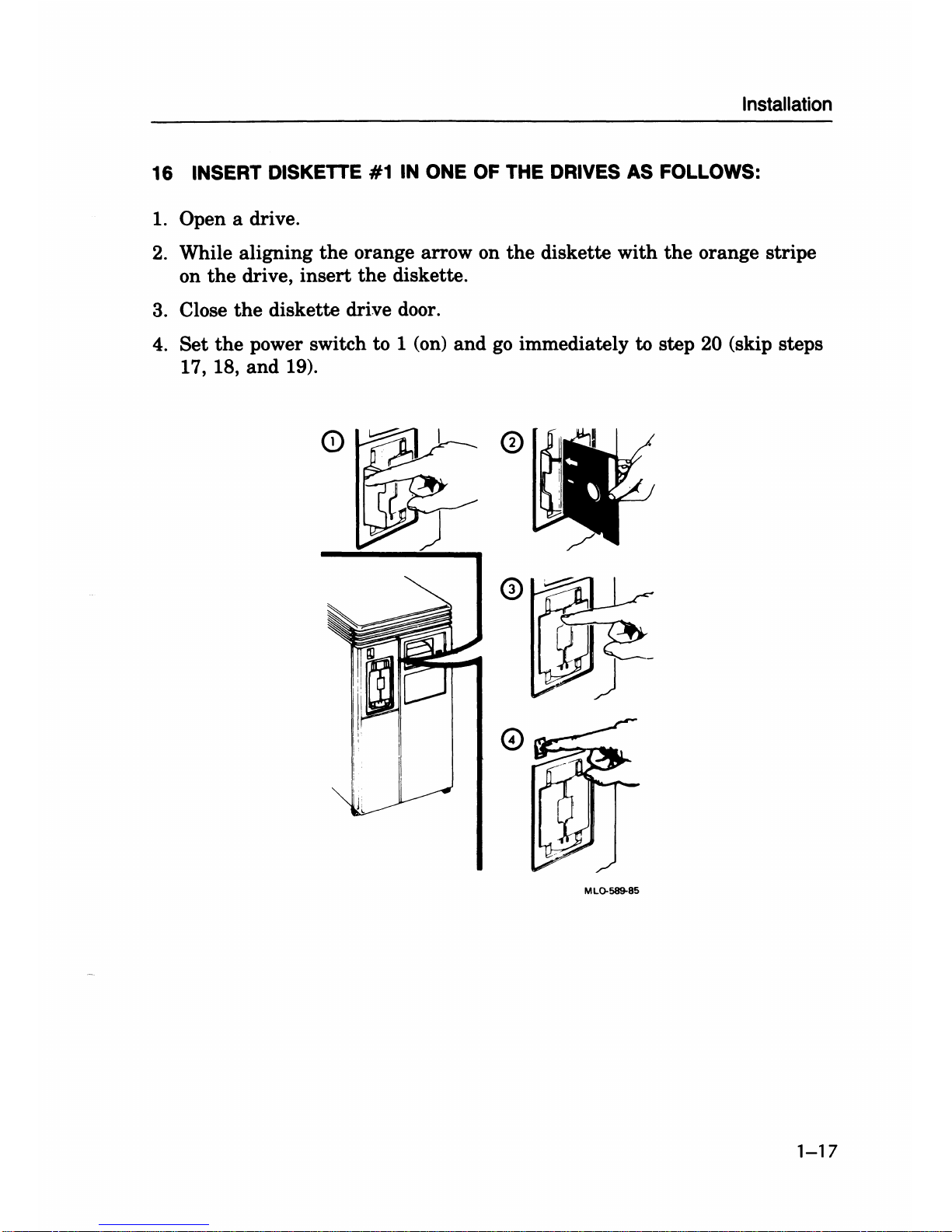
16 INSERT DISKETTE #1
IN
ONE
OF
THE DRIVES
AS
FOLLOWS:
1.
Open a drive.
2.
While aligning
the
orange arrow on
the
diskette
with
the
orange stripe
on
the
drive,
insert
the
diskette.
3. Close
the
diskette drive door.
4.
Set
the
power switch to 1 (on)
and
go
immediately
to
step 20 (skip steps
17, 18,
and
19).
MLQ-589-85
1-17
Installation
Testing with
the
TK50 Tape Drive
17
FIND THE TAPE CARTRIDGE LABELED MVII
D/AG.
CUST.
TK50
IN THE
CARTRIDGE HOLDER
AT
THE FRONT OF THIS MANUAL.
This cartridge contains maintenance system software used to
test
your
Micro
VAX.
Before you
insert
the
cartridge into
the
drive, you should
do
three
things.
1. Make
sure
the
cartridge is write-protected.
2.
Check
the
position of
the
tape
leader inside
the
cartridge.
3.
Check
the
position of
the
tape
leader inside
the
drive.
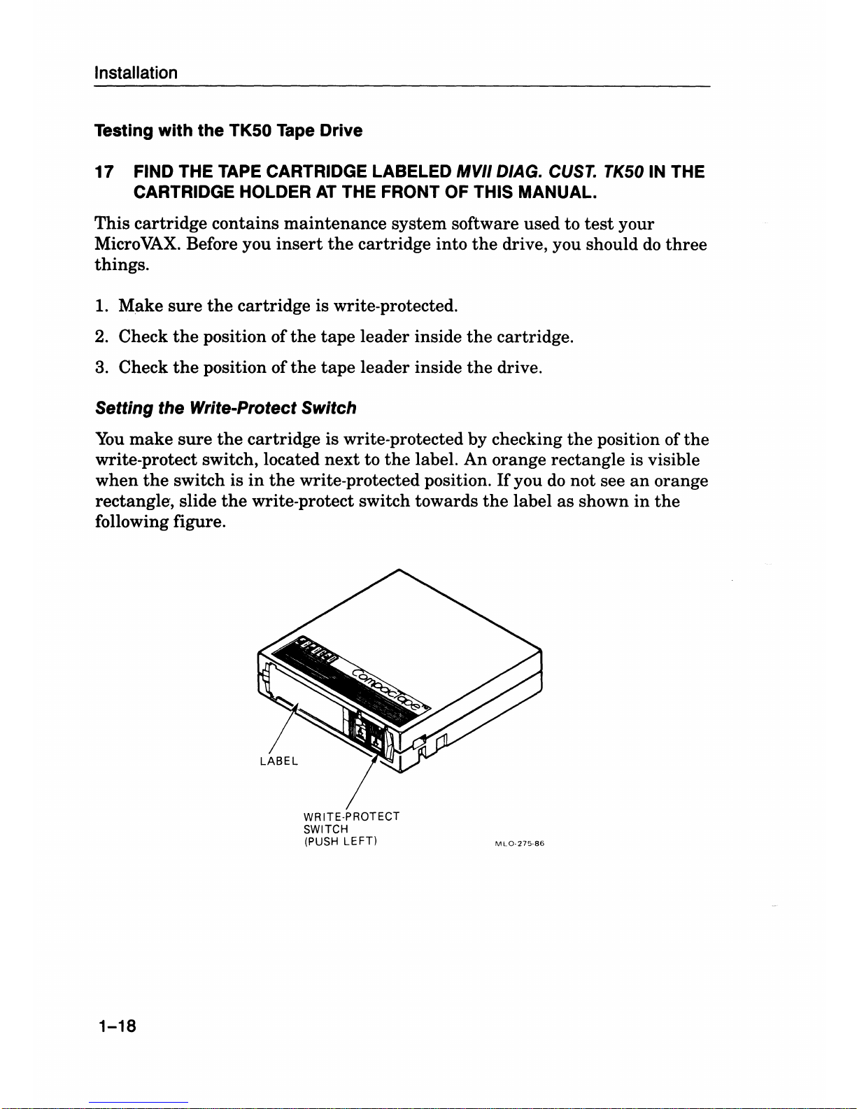
Setting the Write-Protect Switch
You
make
sure
the
cartridge is write-protected by checking
the
position of
the
write-protect switch, located
next
to
the
label.
An
orange rectangle is visible
when
the
switch is
in
the
write-protected position.
If
you
do
not see
an
orange
rectangle, slide
the
write-protect switch towards
the
label as shown
in
the
following figure.
1-18
WRITE·PROTECT
SWITCH
(PUSH
LEFT)
MLO·275·86
Installation
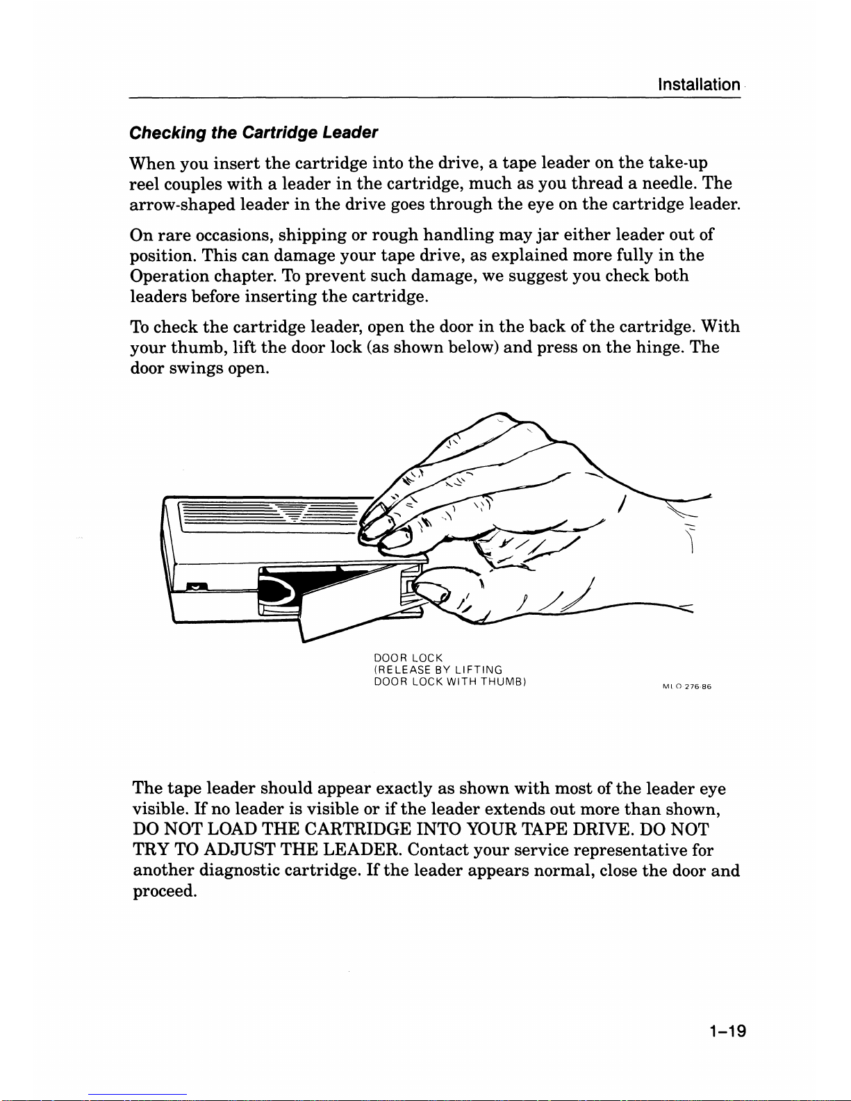
Checking the Cartridge Leader
When
you
insert
the
cartridge
into
the
drive, a
tape
leader
on
the
take-up
reel
couples
with a leader
in
the
cartridge,
much
as
you
thread
a needle.
The
arrow-shaped
leader
in
the
drive goes
through
the
eye on
the
cartridge
leader.
On
rare
occasions,
shipping
or
rough
handling
may
jar
either
leader
out
of
position.
This
can
damage
your
tape
drive,
as
explained
more fully
in
the
Operation
chapter.
To
prevent
such
damage, we
suggest
you check
both
leaders
before
inserting
the
cartridge.
To
check
the
cartridge
leader, open
the
door
in
the
back
of
the
cartridge.
With
your
thumb,
lift
the
door lock (as shown below)
and
press
on
the
hinge.
The
door swings open.
DOOR LOCK
(RELEASE
BY
LIFTING
DOOR LOCK
WITH
THUMB)
Ml0276-86
The
tape
leader
should
appear
exactly
as
shown
with
most of
the
leader
eye
visible.
If
no
leader
is
visible or
if
the
leader
extends
out
more
than
shown,
DO NOT LOAD
THE
CARTRIDGE INTO YOUR TAPE DRIVE. DO NOT
TRY TO
ADJUST
THE
LEADER.
Contact
your
service
representative
for
another
diagnostic
cartridge.
If
the
leader
appears
normal, close
the
door
and
proceed.
1-19
Installation
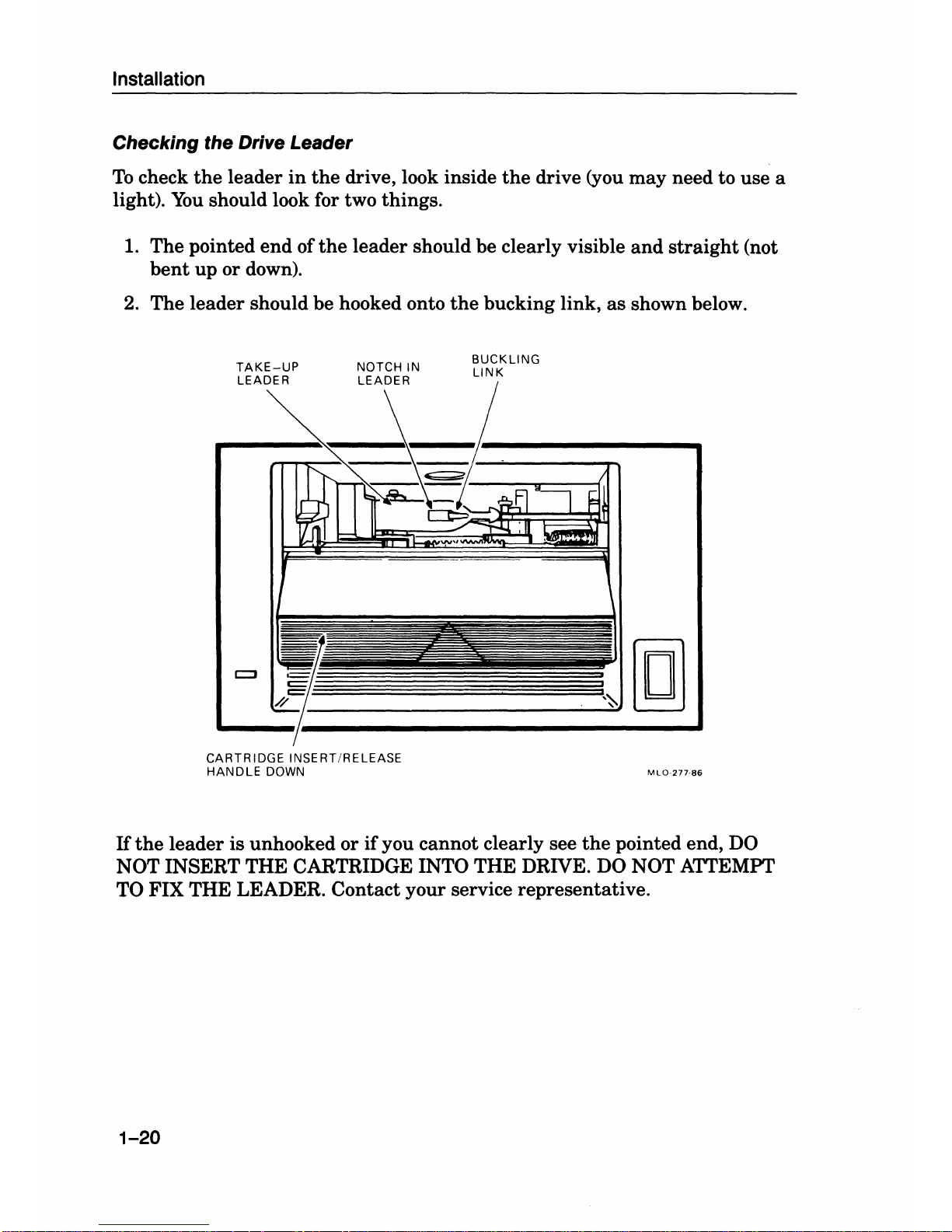
Checking the Drive Leader
To
check
the
leader
in
the
drive, look inside
the
drive (you may need to use a
light).
You
should look for two things.
1. The pointed
end
of
the
leader should be clearly visible
and
straight
(not
bent
up
or down).
2. The leader should be hooked onto
the
bucking link,
as
shown below.
TAKE-UP
LEADER
BUCKLING
LINK
,--~(gJ
CARTRIDGE INSERT/RELEASE
HANDLE
DOWN
Hthe
leader is unhooked or
if
you cannot clearly see
the
pointed end,
DO
NOT INSERT THE CARTRIDGE INTO THE DRIVE. DO NOT ATTEMPT
TO FIX THE LEADER. Contact your service representative.
1-20
 Loading...