

Page 1
Workstations
and
Micro
VAX
2000
Network
Guide
Order
Number
EK-NETAB-UG-002
digital
equipment
corporation
maynard,
massachusetts
Page 2

December
1986
October
1987
The information in this document is subject to change without notice and should not be construed as a
commitment by Digital Equipment Corporation.
Digital
EquipmentCorporationassumesno responsibility for any errorsthat may appear in thisdocument.
The
software,
ifany,
described
in this
documentisfurnished
undera
license
and may be usedor
copied
only
in accordance with the terms ofsuch
license.
No responsibility is assumedforthe use or
reliabUity
ofsoftware
or equipment that is not supplied by Digital Equipment Corporation or its affiliatedcompanies.
Copyright ©1986, 1987 by Digital Equipment Corporation.
All Rights Reserved.
The
READER'S
COMMENTS
form on th^ last page of this document requests the user's critital evaluation to
assist in preparing future documentation.
The following are trademarks of Digital Equipment Corporation:
DEBET
MicroVAX
UNIBUS
DEC
Microns
ULTRIX-32
DECconnect
PDP
ULTRIX-32m
DECmate
P/OS
VAX
DECUS
Professional
VAXcluster
DECwriter
Rainbow
VAXstation
DEQNA
RSTS
VMS
DEUNA
RSX
VT
DIBOL
RT
Work
Processor
MASSBUS
ThinWire
SDSBDSD
TM
ML-S754
Page 3
^
Contents
Preface
vu
Chapter 1
Overview
What
MakesaNetwork?
1-1
Standard
Ethernet
1-1
ThinWire
Ethernet
1-1
Unshielded
Twisted-Pair
Ethernet
1-2
DECnet
1-3
Networking Capabilities of
ULTRIX
1-3
Local
Area
VAXclusters
1-4
Chapter
2
Setting
Up
the
Network
Standard
Ethernet
2-1
Basic ThinWire Components
2-2
ThinWire
Ethernet
Cable
2-3
Connectors
and
Terminators
2-5
Additional Equipment
2-6
DIGITAL
ThinWire Ethernet Multiport Repeater (DEMPR) . . .
2-6
DIGITAL ThinWire Ethernet Station Adapter
(DESTA)
2-7
DEBETs — The Ethernet Bridge
2-8
ThinWire Configurations
2-8
DECconnect Approach
2-9
Daisy-chain Approach
2-10
Combined Daisy-chain
and
DECconnect Approach 2-10
Single Segment Configuration 2-11
Multisegment ThinWire Configuration
2-13
ThinWire
Ethernet
Rules
2-14
Configurations Symbols 2-14
III
Page 4
Single Segment ThinWire Ethernet 2-15
Stand-alone DEMPR
2-17
^
Combined Standard/ThinWire Ethernet LAN 2-18
Stand-alone Cascading DEMPRs
2-19
Stand-alone
DELNI
with
DEMPRs
2-20
Local Bridge 2-21
Disconnecting Stations from ThinWire Ethernet 2-22
Local Area
VAXcluster
Configuration 2-23
Chapter
3
Installing
ThinWire
Hardware
Before
You
Start
3-1
Determining Your Needs
3-1
ThinWire
Ethernet
Cable
3-1
Connectors
3-1
Barrel
Connectors
and
T-Connectors
3-2
DESTA
and
Transceiver
Cable
3-2
Terminators
3-2
DEMPR
3-2
Estimating Your Needs
3-2
Planning the ThinWire Segment
3-3
Setting the Switch for ThinWire Ethernet
3-4
Connecting to a ThinWire Ethernet Segment 3-4
Connecting VAXstation 2000, Micro
VAX
2000, or VAXmate
....
3-5
Connecting a Station with a Transceiver Cable
3-8
Connecting to an Existing ThinWire Network
3-12
How
to
InstallaDEMPR
3-12
Stand-alone
DEMPR
3-13
Connecting
the
DEMPR to Standard Ethernet
3-16
How to Lengthen a ThinWire Segment
3-16
How
to Verify Network Installation for a VAXstation 2000 or
MicroVAX
2000
3-17
How to Verify Installation for a VAXmate
3-18
Troubleshooting the ThinWire Segment
3-18
Troubleshooting the DEMPR
3-19
Troubleshooting the
DESTA
3-19
IV
Page 5
Troubleshooting
Network
Software
3-19
Appendix A Associated Documents
Glossary
Index
Figures
2-1 Settingthe
Switch
for StandardEthernet 2-1
2-2 Connecting the Intermediary Cable 2-2
2-3
ThinWire
Ethernet
Cable
2-4
2-4
Connectors
2-5
2-5 DIGITAL ThinWire Ethernet Multiport Repeater (DEMPR). . .
2-6
2-6
DIGITAL
ThinWire Ethernet Station Adapter
(DESTA)
2-7
2-7
Symbols
for
Cables
2-8
2-8
DECconnect Method of Wiring 2-9
2-9
Single
SegmentConfiguration 2-11
2-10 Connecting
ThinWire
Ethernet to Standard Ethernet 2-12
2-11 Multisegment
ThinWire
Configuration 2-13
2-12 Symbols for Configurations 2-14
2-13
Single
Segment
ThinWire
Configuration 2-16
2-14
Stand-alone
DEMPR
with
ThinWire
Cables
2-17
2-15
DEMPR
on
Standard
Ethernet
2-18
2-16 Stand-alone Cascading
DEMPRs
2-19
2-17
Stand-alone
DELNI
with
DEMPRs
2-20
2-18
Local
Bridge
2-21
2-19 Disconnecting a Station from
ThinWire
Ethernet 2-22
_ 2-20 Local Area VAXcluster 2-24
3-1 Settingthe
Switch
for
ThinWire
Ethernet 3-4
3-2 Connectingthe T-connector to
ThinWire
3-5
3-3 Connectinga Terminator to the T-connector 3-6
3-4 Adding a Segment to the T-connector 3-6
Page 6
3-5 Connecting the
T-connectortoVAXstation
2000
3-7 _
3-6
Connecting the T-connector to ThinWire
3-8
3-7
Connecting a Terminator to the T-connector
3-9
3-8
Adding a Segment to the T-connector 3-9
3-9
Attaching the T-connector to the
DESTA
3-10
3-10
Attaching the Transceiver Cable to the DESTA 3-11
3-11
ThinWire Cables Connected to the DEMPR
3-13
3-12 Attaching a Terminator to a
ThinWire
Segment
3-14
3-13
Terminator Connected to the DEMPR
3-15
3-14
Connecting Two ThinWire Sections 3-16
Tables
2-1 Ordering Information for ThinWire Ethernet Cables
2-4
3-1 Formto Order
ThinWire
Equipment 3-3
VI
Page 7
Preface
This manual describes how to configure and install some simple ThinWire
Ethernet
networks
for VAXstation 2000, MicroVAX2000,orVAXmate systems.
It does not describe all possible configurations, but outlinesthe rules to
follow
when configuring your network with ThinWireEthernet.
Recommended
Reading
Path
1. VAXstation 2000 Hardware Installation Guide, MicroVAX 2000 Hardware
Installation
Guide,
or
VAXmate
System
Handbook.
You should install your
VAXstation
2000, or
VAXmate
system before installing ThinWireEthernet.
2.
Workstations
and
MicroVAX
2000
Network
Guide,
Chapter 2. This chapter
tells you how to configure your network.
3.
Workstations
and
MicroVAX
2000Network
Guide,
Chapter 3. This chapter
describes
how
to install ThinWire Ethernet
hardware
on
your
system.
A
glossary
at the end of the book
explains
technical
terms
usedin this
book.
Conventions
The following notices appear throughout this guide:
• Notes — Contain general or supplemental information about a topic.
• Caution — Contain information to prevent disruption of the network.
Convention
Meaning
Bold
Notes, cautions,
and
warnings are bolded.
Italics
Terms defined in the glossary are italicized the first
time
the
word appears in the text.
VII
Page 8
Document
Structure
This manual consists of three chapters and an appendix.
• Chapter 1 gives an overview of ThinWire Ethernet, defines networks,
and
describes
DECnet,
ULTRIX
networks,
and
VAXclusters.
• Chapter 2
describes
the
basic
components you will need, some
simple
configurations, and the rules for connecting to ThinWire Ethernet.
• Chapter 3 describes how to determine your needs and how to install and
troubleshoot
a
Thin
Wire
Ethernet
network.
• Theappendixlistsassociated documents that mightbe helpfulin planning
your
network.
VIII
Page 9
^
Chapter
1
Overview
Networks
are
useful
to
people
who
need to
work
together
and
share
information
but
still
want
the attractive features of their
own
workstation.
People
working
cooperativelyona
project
may
needtocommunicate
and
exchange
information,
share
common
data
bases,
share
files,oruseamail
system,
and
yet
keep
their
workstation
independent.
Networks
also
allow
you to share
devices,
suchas
laser
printers
or line
printers.
What
Makes
a
Network?
A
network
is a
group
of
computers
connected
by
communications
lines
to
share information and
resources.
You
need
special
network hardware and
software
to
connect
your network.
DECnet
software
enables
computers
to
formanetwork.
Standard
Ethernet
Ethernet is the
DIGITAL
local area network. Ethernetnetworks provide rapid
access
to data in remote locations, and the high data rate supported by
DIGITAL'S
DECnet software makes file transfers practical.
In
baseband
Ethernet
(StandardorThinWire),asingle
network
cable
replaces
the
numerous
interconnecting
cablesintraditional
data
networks.
Standard
Ethernet cable is recommended for commimications between floors and
buildings.
ThinWire
cable
is
recommended
for
communications
between
workstations,
personal
computers,
and
low-end
systemsinlocal
work
areas
onafloor.
ThinWire
Ethernet
ThinWire
is a
networking
cabling
system
and set of
products
that
deliver
10
megabits-per-second
Ethernet
to the
desk,
work
area,
and
local
area
systems
for
connection
of
personal
computers,
workstations,
network
servers,
and
low-end
computing
devices.
All
DIGITAL
Ethernet products can
connect
to
ThinWire
offering
an
alternative
wiring
approach
for
low-end,
mid-range.
Overview
1—1
Page 10

and
high-end
systems
and
Ethernet
servers
without
any
changeinnetwork
performance.
, ^
ThinWire Ethernet is used in any size environment. It is ideal for a small
stand-alone network in which personal computer and workstation users
share resources, such as prmters and storage devices.
ThmWire
works
well as a small- to medium-sized stand-alone
local
area
network
(LAN)
in a small business or in a department of a larger organization where
personal
computer
and
workstation
users
need
local
resource
sharing
and
more
powerful
computing
resources.ALAN
isa high-speed
communications
network that covers a limited geographical area, such as a section of a
building, an entire building, or a
cluster
of buildings.
Unshielded
Twisted-Pair
Ethernet
The
Unshielded
Twisted-Pair
Ethernet
Adapter
delivers
10
megabits-per-
second
Ethernet
performance
to the
desktop,
work
area,
and
local
system
over unshielded twisted-pair building cable.
Unshielded tvdsted-pair adapters connect a
single
device,
•
DESTA
with
Micro
VAX
attached
•
VAXmate
•
VAXstation
2000
• Personal computer with DEPCA, DELUA, or DELQA Ethernet controllers
to the Ethernet network by means of the
DIGITAL
ThinWire Ethernet
Multiport Repeater
(DEMPR).
Small stand-alone local area networks, where a
personal
computer
and
workstation
usershare
limited
local
resources
(printers,
storage
devices),
can be connected as a subnetwork to large local area and
wide
area
networks.
Functionally, the
office
adapter and wiring
closet/SER
adapter work as a
pair to match the 50-ohm impedance on a ThinWire Ethernet coaxial cable
to the impedance on an unshielded twisted-pair cable. Thus, unshielded
tv«sted-pair building wiring can be used, in addition to ThinWire cable, to
run Ethernet to the desktop.
Unshielded Twisted-PairEthernet Adapters are compatiblewith the ThinWire
Ethernet products and
IEEE
802.3
specificationsfor "MediumAttachment Unit
and Baseband Medium Specifications for Type 10 Base 2."
1 —2
Workstations
and
MicroVAX
2Q00
Network
Guide
Page 11
The
maximum
length of 24
AWG
unshielded twisted-pair
cable
that can be
used between the
office
adapter and the wiring closet adapter is 50 to 70
meters (164 to 230 feet).
DECnet
DECnet, a software product that enables many
DIGITAL
computer systems
to form a network, is derived from a well-defined network architecture called
the
DIGITAL
Network Architecture (DNA). DNA, similar to the standard
International Standards Organization
(ISO)
communication architecture, is
the
logical
structure that
provides
a
model
for
DECnet
implementations.
DECnet provides:
• Task-to-task communications — allows programs executing in different
systems to exchange information.
• File transfer — supports the copying of
files
among different systems.
• Remote file access — allows
the
user to read, write, delete, or modify
files on another system.
• Remote
command
file submission
and
execution — allows
one
computer
system
to
direct
another
system
to
execute
commands
and/or
perform
tasks.
• Down-line loading — allows programs developed on a system with
appropriate peripherals and
resources
to be sent to another
system,
such
as a small, memory-only system, for execution.
• The network virtual terminal — gives a user cormection to a remote
system;
the terminal operates as if it were connected to the
remote
system.
•
Network
management —
provides
for
monitoring
and
controlling
network
operation in a distributed environment.
Networking
Capabilities
of
ULTRIX
TCP/IP networking protocols are standard wth the
ULTRIX-32
software.
They are an integral part of the operating system and facilitate interaction
with Internet networks. Support includes
iMe
transfer, remote execution,
remote login, and resource-sharing capabilities with other systems running
the
TCP/IP
protocols.
DECnet-ULTRIX
provides an Ethernet-based communication link between
VMS
and
ULTRIX
operating systems.
ULTRIX
bridgesboth environmentsby
supporting the
coexistence
of the
DECnet
and TCP/IP
protocols.
DECnet
Overview
1-3
Page 12
and TCP/IP can run simultaneously and share the same system
resoiwces,
such
as
the
DEUNA
and
DEQNA
Ethernet
interfaces.
This
feature
allows
a
DECnet-ULTRIX
system to act as an informal gateway between DECnet
networks
and
Internet
networks.
DECnet-ULTRIX
allows
ULTRIXtointeract
with other
DIGITAL
and
non-DIGITAL
operating systems, using
DECnet
products such as DECnet-RSX, DECnet-VAX, DECnet-DOS.
Local
Area
VAXclusters
The
computer
industry
today
provides
individuals
or
small
work
groups
in
organizations with their own personal computer systems or workstations,
solving the computing availability problem but creating a new set of
problems — managing large numbers of
geographicaUy
dispersed personal
workstations. Another problem for users is that they have inherited system
management responsibilities and need to have more knowledge of the
operating system to perform system management tasks.
The
Local
Area
VAXcluster
using ThinWire or standard Ethernet as the
interconnect allows
DIGITAL'S
low-end
VAX/MicroVAX
products to be
grouped in similar
VMS
worksystems, removing the problems of system
management on a per node basis and elevates it. to a single system
management domain. Except for the interconnect-dependent driver software,
the
same
VAXcluster
softwareisused
on
both
Cl-based
clusters
and
ThinWire
or
standard
Ethernet-based
clusters.
The
Local
Area
VAXcluster
systemalsosolvesthe problemsofinadequatedisk
space and data sharing among members of a group or team.
VAXclusters
provide distributed processing capabilities to allow load-sharing batch and
print processing across member nodes or to target a node, reducing the
amount of wasted or underutilized computes.
One other problem is MicroVMS has to be installed on every Micro
VAX
or
VAXstation.
In a LocalArea
VAXcluster,
the system requires no local software
installation and can be plugged into a suitable ThinWire or standard Ethernet
connection
and
be remotely booted, removing the
need
for local software
installation.
Special software allows membership in a
Local
Area
VAXcluster.
This
software provides flexibility by allowing many Local Area
VAXclusters
to
share the same Ethernet or ThinWire Ethernet segment
and
to allow nodes to
logically move from
pne
cluster to another.
1-4
Workstations
and
MicroVAX
2000
Network
Guide
Page 13
Chapter
2
Setting
Up
the
Network
This
chapter
describes
the
basic
components
you
will
need,
some
simple
topologies,
and
the
rules
for
connectingasystemtoThinWire
Ethernet.
This
chapter
also
describes
howtoset
up
your
systemtoconnecttostandard
Ethernet.
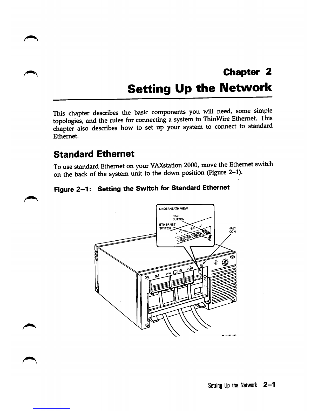
Standard
Ethernet
To
use
standard
Ethernetonyour
VAXstation
2000,
move
the
Ethernet
switch
onthe
backofthe
system
unittothe
down
position
(Figure
2-1).
Figure
2-1: Setting the Switch for Standard Ethernet
UNDERNEATH
VIEW
BUTTON
ETHERNET
SWITCH
HALT
ICON
SettingUpthe
Network
2—1
Page 14
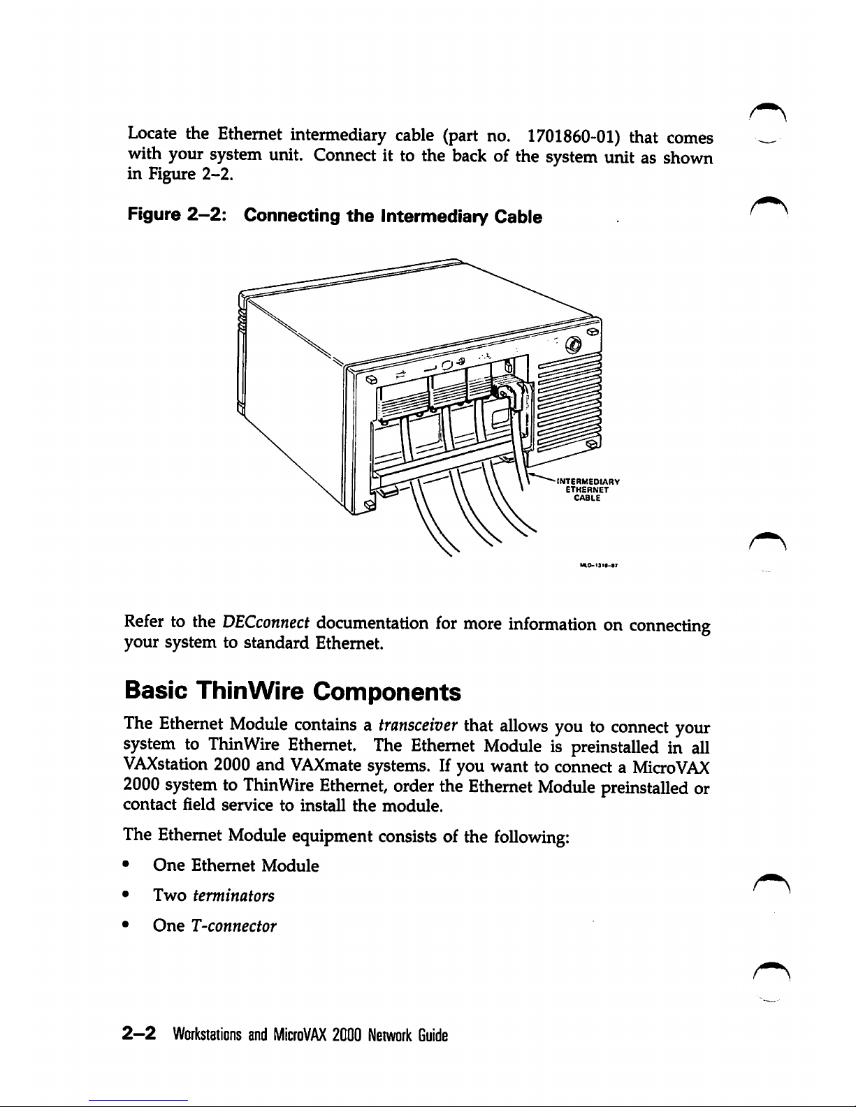
Locate
the
Ethernet
intermediary
cable
(part
no.
1701860-01)
that
comes
with your
system
unit.
Connect
it to the
back
of the
system
unit as
shown
in Figure
2-2.
Figure
2-2:
Connecting
the
Intermediary Cable
INTERMEDtARV
ETHERNET
CABLE
Refertothe
DECconnect
documentation
for
more
informationonconnecting
your
system
to
standard
Ethernet.
Basic
ThinWire
Components
The
Ethernet
Module
containsatransceiver
that
allows
youtoconnect
your
system
to
ThinWire
Ethernet.
The
Ethernet
Module
is preinstalled in all
VAXstation
2000
and
VAXmate
systems.
If you want to
connectaMicro
VAX
2000
systemtoThinWire
Ethernet,
order
the
Ethernet
Module
preinstalled
or
contact
field
service
to
install
the
module.
The
Ethernet
Module
equipment
consists
of the
following:
•
One
Ethernet
Module
•
Two
terminators
•
One
T-connector
2—2
Workstations
and
MicroVAX
2000
Network
Guide
Page 15
Contact your
DIGITAL
representative to order ThinWire cable lengths with
connectors
at
each
end.
If you prefer, you can purchase ThinWire Ethernet cable on a
Ispool
and cut
the cable to your needs. See the
VAXstation
2000/MicroVAX
2000
Maintenance
Guide for information on cutting and crimping ThinWire Ethernet cable.
Before reading about configurations, you need to know the following terms:
• Station — A single addressable device on a
Local
Area Network; for
example, a VAXstation 2000, Micro
VAX
2000, or
VAXmate.
• Section — A single continuous piece of coaxial cable.
• Segment — Any number of ThinWire sections joined by
barrel
connectors
or T-connectors to form a single, continuous cable.
ThinWire
Ethernet
Cable
ThinWire Ethernet cable has a jacket of either polyvinyl chloride
(PVC)
or
Teflon. Either PVC or
Teflon
cable can be used in an open office area.
However, in the Uruted States, Teflon may be required for areas classified
by the Underwriter's Laboratory (UL) as environmental air spaces, such as
in air-conditioning ducts or air plenum. An air plenum is a compartment or
chamber to which
one
or more compartments are connected in a building
ventilation system
and
is only used for carrying envirorunental air. Check
your local building codes for more information.
ThinWire Ethernet cable delivers 10 megabits-per-second performance and
full Ethernet functionality.
The maximum length of a segment is 185 m (606 ft).
ThinWire Ethernet products adhere to the
IEEE
standard 802.3. ThinWire
Ethernet products are compatible with products that conform to this
international
standard.
ThinWire
Ethernet
cable
is:
•
Flexible
• Fully compatible with standard Ethernet
• Inexpensive
• High performance
SeningUpthe
Network
2-3
Page 16
You can order ThinWire Ethernet cables in the following cable lengths:
Table
2-1:
Ordering
Information
for
ThinWire
Ethernet
Ca-
bles
Order
No.
Description
BC16M-06
ThinWire
Cable,
PVC,
6'
BC16M-15
ThinWire
Cable,
PVC,
15'
BC16M-30
ThinWire
Cable,
PVC,
30'
H8243-A ThinWire Cable, PVC, 1000' spool
H8244-A ThinWire Cable, Teflon, 1000' spool
Figure
2-3
shows the ThinWire Ethernet cable.
Figure
2-3:
ThinWire
Ethernet
Cable
2-4
Workstations
and
MicroVAX
2000
Network
Guide
Page 17
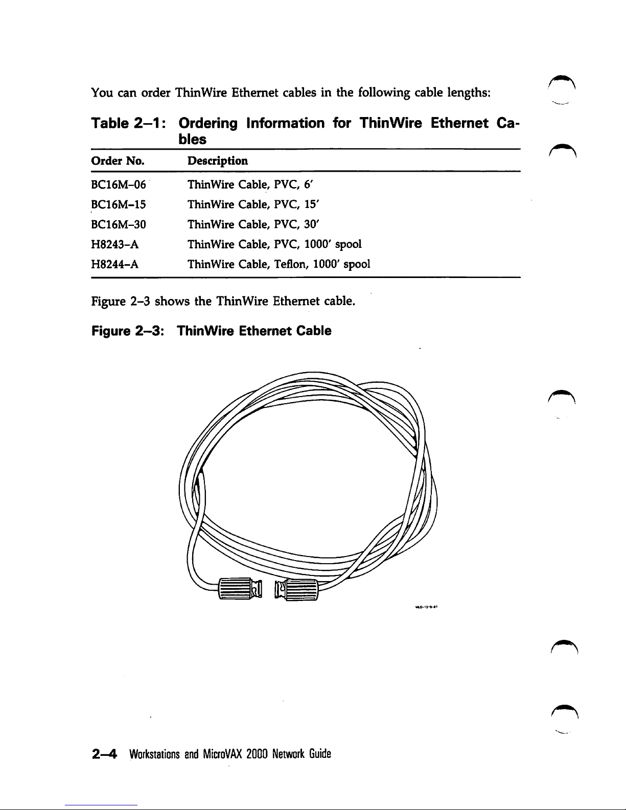
Connectors
and
Terminators
The
ThinWire
connectors
andterminators youneedto
configure
your
network
follow:
•
T-connector
(H8223)
— A
3-way
connector
that
joins
two
ThinWire
Ethernet
cable
sections.
Thethird
opening
attaches
to a
VAXstation
2000,
MicroVAX
2000,
or
a VAXmate
system.
•
Terminator
(H8225)
— A
cormector
at the end of a
ThinWire
segment
that
provides
the
50-ohm
termination
resistance
needed
for
the
cable.
If
the ThinWire cable connects to a
DIGITAL
ThinWire Ethernet Multiport
Repeater
(DEMPR),
thenaterminatorisonly
neededatone
end
of
the
cable.
•
Barrel
connector
(H8224)
— A recessed connector that connects two
ThinWire
Ethernet
cable
sections.
Figure
2-4
shows
the
connectors
you
needtoconnecttoThinWire
Ethernet.
Figure
2-4:
Connectors
CONNECTOR
s
BARREL
CONNECTOR
T-CONNECTOR
CONNECTOR
SettingUpthe
Network
2-5
Page 18
Additional
Equipment
Use the following equipment for additional configurations:
•
DIGITAL
ThinWire Ethernet Multipart Repeater(DEMPR-AA)
•
DIGITAL
ThinWire Ethernet StationAdapter (DESTA-AA)
• Ethernet Bridges (DEBET-AA)
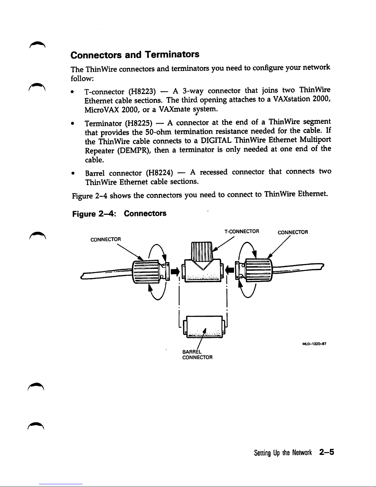
DIGITAL
ThinWire
Ethernet
Multiport
Repeater
(DEMPR)
A
DEMPR
is a repeater, a
device
used to extend the length,
topology,
or
intercormection of the physical network medium beyond the limits imposed
by a single segment.
You
can connectup to eight ThinWire Ethernet segments to a single
DEMPR
to form a single Local Area Network. Or, you can connect a ThinWire LAN
to standard Ethernet through the
DEMPR.
Eachsegment can have 29 stations
(the 30th position is taken by the
DEMPR)
for a total of up to 232 stations.
Figure
2-5
shows
the
DEMPR.
The
DEMPR
offers:
• Support of up to eight ThinWire Ethernet connections
• Support of multiple Ethernet devices for each connection
• Easy installation
Figure
2-5:
DIGITAL
ThinWire
Ethernet
Multiport
Repeater
(DEMPR)
MLO-1321-87
2-6
Workstations
and
MicroVAX
2000
Network
Guide
Page 19
DIGITAL
ThinWire
Ethernet
Station
Adapter
(DESTA)
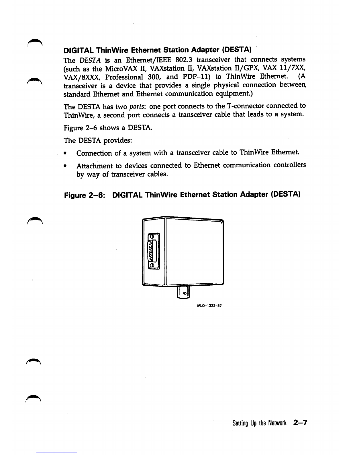
The
DESTA
is an Ethemet/BEEE 802.3 transceiver that connects systems
(such
as the
Micro
VAX
II,
VAXstation
II,
VAXstation
II/GPX,
VAX
11/7XX,
VAX/8XXX,
Professional
300,
and
PDP-11)
to
ThinWire
Ethernet.
(A
transceiver is a
device
that provides a
single
physical
connection
betweerii
standard Ethernet
and
Ethernet communication equipment.)
The
DESTA
has two
ports:
one port
connects
to the
T-connector
connected to
ThinWire, a second port connects a transceiver cable that leads to a system.
Figure 2-6 shows a
DESTA.
The DESTA provides:
•
Connection
ofa
system
with a
transceiver
cabletoThinWire
Ethernet.
•
Attachment
to devices
connected
to
Ethernet
communication
controllers
by way of transceiver cables.
Figure
2-6:
DIGITAL
ThinWire Ethernet Station Adapter
(DESTA)
M.O-1322-87
SeningUpthe
Network
2-7
Page 20
DEBETs
—
The
Ethernet
Bridge
Ethernet bridges
(DEBET)
connect standard Ethernet LANs to each other, thus
creating an extended LAN. An extended LAN configuration has the potential
to span a much greater area than a single standard Ethernet LAN.
DEBETs
provide network traffic control to prevent an extended LAN from
being overwhelmed by the combined traffic on each of its standard LANs.
DEBETs
confine local traffic in a standard Ethernet LAN. Only traffic that is
destined
for
another
standard
LAN
is
allowed
to
cross
over
the
DEBET.
ThinWire
Configurations
A ThinWire configuration is an economical way to connect VAXstation 2000s,
Micro
VAX
2000s, or VAXmates in a network configuration.
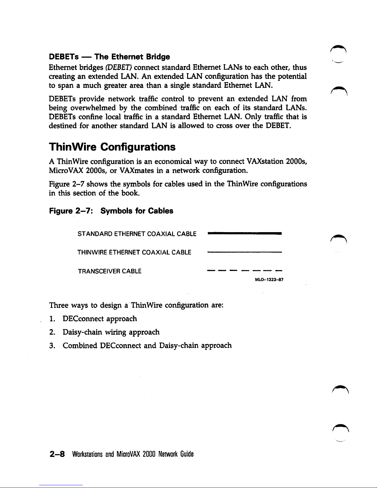
Figure
2-7
shows the symbols for cables used in the ThinWire configurations
in
this
section
of
the
book.
Figure
2-7:
Symbols
for
Cables
STANDARD
ETHERNET
COAXIAL
CABLE
THINWIRE
ETHERNET
COAXIAL
CABLE
TRANSCEIVER
CABLE
MLO-1323-87
Three ways to design a ThinWire configuration are:
1. DECconnect approach
2. Daisy-chain wiring approach
3. Combined DECconnect and Daisy-chain approach
2-8
Workstations
and
MicroVAX
2000
Network
Guide
Page 21
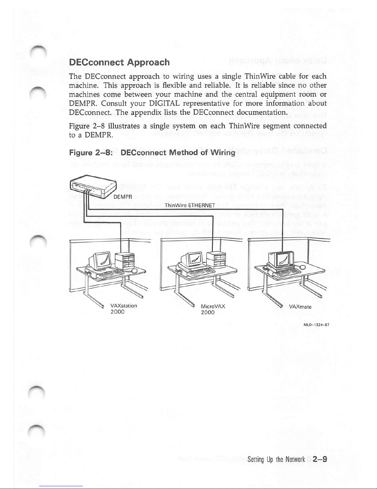
DECconnect
Approach
The DECconnect approach to wiring uses a single ThinWire cable for each
machine. This approach is flexible
and
reliable. It is reliable since no other
machines come
between
your machine
and
the
central
equipment
room or
DEMPR. Consult your
DIGITAL
representative for more information about
DECconnect. The appendix lists the DECconnect documentation.
Figure
2-8
illustrates a single system on each ThinWire segment connected
toaDEMPR.
Figure
2—8:
DECconnect
Method
of
Wiring
VAXstation
2000
ThinWire
ETHERNET
MicroVAX
2000
VAXmate
SettingUpthe
Network
2-9
Page 22

Daisy-chain
Approach
^
The other approach to ThmWire configurations used in this book is the
daisy-chain method of wiring. Several machines are connected to the same
ThinWire segment. This segment can function as a stand-alone network or
can be connected to a central equipment room.
Thisapproach lowersthe costofwiring,but there is a riskthat someonemight
improperly unplug a system and make the network connections between
systems on the same ThinWire segment inoperative.
Combined
Daisy-chain
and
DECconnect
Approach
A third way to improve reliability and lower costs would be to combine the
Daisy-chain and DECconnect approaches.
To do this, run a single ThinWire cable from the
DEMPR
in the central
equipmentroom to a work group. The members of the work group can then
daisy-chain their equipment from this wire. By isolating the daisy-chain in
a work group, members of the work group can control the wiring of their
part of the network. Thisprocedure eliminates the risk of any outsidegroups
improperly unplugging a system and disrupting the network.
2—10
Workstations
and
MicroVAX
2000
Network
Guide
Page 23

Single
Segment
Configuration
Figure
2-9 illustratesa ThinWireconfiguration in an
office
environmentwhere
VAXstation
2000, Micro
VAX
2000, and
VAXmate
systems are serially linked
to a single segment of ThinWireEthernet cable in a localarea network
(LAN).
Chapter 3 describes how to connect systems with ThinWire cable.
Figure
2-9:
Single
Segment
Configuration
VAXstation
2000
ThinWire
MicroVAX
2000
VAXmate
MLO-1325-87
A local area network may be part of a larger network. For example, a
department of a large company that uses ThinWire Ethernet in a LAN,
shown in Figure 2-9, to communicate in its own department may also
communicate with other departments in the company. In Figure 2-10, the
department's localarea networkis connectedto the company's largernetwork
by a hardware device called a
DEMPR.
The
H4000
shown in Figure 2-10 is a
transceiver that provides a single connection between standard Ethernet and
Ethernet
communication
equipment.
SellingUpihe
Network
2-11
Page 24

N)
I
IS)
Figure
2-10:
Connecting
ThinWire
Ethernet
to
Standard
Ethernet
Ih4000|—H
H4000[
I
) )
STANDARD
ETHERNET
H4000
VAXstation
ll/GPX
VAXstation
DEMPR
ThinWire
ETHERNET
VAXstation
MicroVAX
2000
2000
)
H4000
MicroVAX
II
VAXmate
•|
H4000|
1
'
/•
V
VAX
8600
) O
Page 25

Multisegment
ThinWire
Configuration
Figure
2-11
illustratesamultisegment
ThinWire
configuration
that
uses
the
DEMPR to connect several ThinWire segments.
Figure
2-11:
Muitisegment
ThinWire Configuration
VAXstation
2000
DEMPR
VAXstation
ThinWire
Segment
A
ThinWire
Segment
B
MicroVAX
VAXmate
McroVAX
VAXmate
SettingUpthe
Network
2-13
Page 26

ThinWire
Ethernet
Rules
This
section
describes
the
rules
for:
• Setting up:
• A single segment ThinWire Ethernet LAN
• A
stand-alone
DEMPR
• A combined standard/ThinWire Ethernet LAN
• Stand-alone cascading
DEMPRs
•
Stand-alone
DELNI
with
DEMPRs
• Disconnecting stations from ThinWire Ethernet
Configurations
Symbols
Figure 2-12 shows the symbols used in this section.
Figure
2-12:
Symbols for Configurations
STANDARD
ETHERNET COAXIAL CABLE
THINWIRE ETHERNET
COAXIAL
CABLE
TRANSCEIVER
CABLE
TERMINATOR
T-CONNECTOR
ETHERNET
TRANSCEIVERS
STATION
LOCAL
BRIDGE
2-14
Workstations
and
MicroVAX
2000
Network
Guide
1=]
•
BRIDGE
mm
MLO-1328-87
Page 27

Single
Segment
ThinWire
Ethernet
The
following
rules
for
single
segment
ThinWire
Ethernet apply to all
ThinWire Ethernet configurations:
• The maximum allowable length of a ThinWireEthernet segment is 185
m
(606
ft).
Each
segment can
consist
of smaller
sections
connected by
barrel
connectors
or
T-connectors.
• Stations must be attached to T-connectors. No ururepeated segments can
extend off the
main
segment.
• At least 0.5 m (1.6 ft) must be between stations.
• The maximimi number of stations allowed on a segment is 30. If you use
a barrel connector to connect two sections of cable, you must decrease
the allowed number of stations by one for each barrel connector used.
• One 50-ohm terminator must be at each end of a segment. If a segment
is attached to a
DEMPR,
then only one terminator is needed on the end
not
attached
to
the
DEMPR
because
the
DEMPR
has
terminators
built
into
it.
• Only one earth
ground
point is
necessary.
If the station is attached to a
DEMPR,
the DEMPR provides this ground point.
• ThinWire Ethernet networks must adhere to the Ethernet 2-repeater rule:
no more than two repeaters between any two stations. A repeater
providesameans
of
extending
Ethernet
networks
beyond
the
limits
imposed
by a
single
segment.
The
DEMPR
counts
as a
single
repeater.
•
ThinWire
Ethernet
networks
cannot
exceed
the
Ethernet
1024-station
limit
for
each
area.
•
ThinWire
segments must remain in a building or a
complex
of buildings
that
shares
common
structural
steel.
SeningUpthe
Network
2-15
Page 28

Figure
2-13 shows a
single
segment of
ThinWire
cable
with stations
connected.
Figure
2—13:
Single
Segment
ThinWire Configuration
185m(606
ft)
MAXIMUM
7^
TJ
(dest^
^
0.5m(1.65
ft)
MINIMUM
UP
TO
30
STATIONS
2—16
Workstations
and
MicroVAX
2000
Network
Guide
/
-CONNECTOR
/
TERMINATOR
MU3-1329.47
Page 29

Stand-alone
DEMPR
A stand-alone DEMPR is a DEMPR that is
not
connected to a larger network.
Eachsegment attached to a
DEMPR
must use the guidelines for singlesegment
ThinWire Ethernet
and
the following guidelines:
• One to eight ThinWire cables can be attached to a DEMPR.
• Each cable can be up to 185 m (606 ft) long.
• Each cable can have up to 29 stations (the 30th position is taken by the
DEMPR).
• Segmentsconnectedto the
DEMPR
must NOT be grounded. The
DEMPR
internally grounds the eight ThinWire segments.
Figure 2-14 shows a stand-alone
DEMPR
with ThinWire cables.
Figure
2-14:
Stand-alone
DEMPR
with
ThinWire
Cables
185m(606
ft)
MAXIMUM
S
//-
T/
DEMPR
V/-
UP
TO
29
STATIONS
PER
THINWIRE
SEGMENT
[p
[p
I- 1
0.5m(1.65
ft)
MINIMUM
MLO-1330-87
SeningUpthe
Network
2-17
Page 30

Combined
Standard/ThinWire
Ethernet
LAN
This configuration follows the guidelines for the stand-alone
DEMPR.
In
addition are the following guidelines:
• The
DEMPR
can attach to a regular Ethernet by a transceiver or a
DELNI.ADELNI
is a
local
network
interconnect
product
that
provides
eightseparate network interfaces froma
single
transceiver tap.
• If you
connectaDEMPR
to standard
Ethernet
by a
DELNI,
you must
connect the
DELNI
to Ethernet by an
H4000-BA.
The H4000-BA is a
transceiver that provides a single connection between standard Ethernet
and Ethernet communication equipment.
Note: If you are connecting your ThinWire Ethernet network to a
larger network, consult the
network
coordinator to make sure that you
have a unique node for your system and are adhering to the network
configuration rules.
Figure
2-15
shows
a DEMPR
onastandard
Ethernet coaxial cable.
Figure
2-15:
DEMPR
on
Standard
Ethernet
2.5m(8.25
ft)
—
MINIMUM
—I
C3
UP
TO
100
TRANSCEIVERS
5 m
(16.5
ft) TO I
50m(165
ft)—H
a
185m(606
ft)
MAXIMUM
DEMPR
S
7^
UP
TO
29
STATIONS
PER
THINWIRE
SEGMENT
1°^
I
2-18
Workstations
and
MicroVAX
2000
Network
Guide
0.5m(1.65
ft)
MINIMUM
MLO-I331-e7
Page 31

Stand-alone
Cascading
DEMPRs
This configuration follows the guidelines for the stand-alone DEMPR and the
following guidelines:
• Cascading DEMPRs cannot be connected to a standard Ethernet LAN.
• Up to two DEMPRs are allowed between stations. Therefore, you can
cascade
DEMPRs
on
one
of
the
ThinWire
cables
attached
toaDEMPR.
You must use a DELNI to cascade DEMPRs as
shown
in Figure 2-17.
• The ThinWire cable with the cascading DEMPRs can be up to 185 m
(606 ft) long.
• Connect the DEMPRs to ThinWire cable, using DESTA transceivers.
• Up to 29 DESTAs (with their corresponding DEMPRs) are allowed on the
ThinWire
cable.
• At
least
0.5 m (1.6 ft) of cable
must
be
between
DESTAs or stations.
Figure
2-16
shows stand-alone cascading DEMPRs.
Figure
2-16:
Stand-alone
Cascading
DEMPRs
185m{606
ft)
MAXIMUM
0.5m(1.65
ft)
h—
MINIMUM
UPTO 29
DESTAs
|
DESTA
|
WITH
DEMPRs
I
DEMPR
DESTA
I
DEMPR
DEMPR
5 m
(16.5
ft)
TO
50m(165
ft)
MLO-1332-87
SettingUpthe
Network
2—19
Page 32

Stand-alone
DELNI
with
DEMPRs
The guidelines for a stand-alone DELNI with DEMPRs are:
• Using the DELNI in global mode with a loopback connector attached to
the ninth port, you can connect up to eight
DEMPRs,
using 5 to 50 m
(16.5 to 165 ft) of transceiver cable for each DEMPR.
• Because only two DEMPRs are allowed between stations, you cannot
have a cascading DEMPR on a DEMPR attached to a DELNI.
•
Conventions
for
ThinWire
cables
connected
to
the
DEMPRs
are
the
same
as
those
defined
forastand-alone
DEMPR.
Figure
2-17
shows a stand-alone DELNI with DEMPRs.
Figure
2-17:
Stand-alone
DELNI
with
DEMPRs
5 m
(16.5
ft) TO
50m(165
ft)
±
DELNI
Tt
OEMPR
DEMPR
DEMPR
I
IL-
DEMPR
DEMPR
DEMPR
DEMPR
DEMPR
MLO-1333-87
2-20
Workstations
and
MicroVAX
2000
Network
Guide
Page 33

Local
Bridge
Basic configuration guidelines are:
• A local bridge joins two LANs by transmitting signals over connecting
transceiver
cables.
Each
transceiver
cable
can
be
5 to 50 m (16.5 to 165
ft) long.
• A bridge allows you to get around the 2-repeater rule. Once a message
goes through a bridge, two more repeaters can be used in the next LAN
to extend the network. Up to seven bridges are allowed between stations.
• A bridge acts as a LAN filter. Only messages addressed to stations on
the other side of the bridge will pass through the bridge.
Figure
2-18 shows a local bridge connecting two segments of
ThinWire
Ethernet.
Figure
2-18:
Local
Bridge
IPESTAI
I 5 m
(16.5
ft)
TO-^1
50m
(165
ft)
j
I
BRIDGE
I
!-^5m(16.5ft)
TO
I 50 m (165
ft)
|desta|
IDESTAI
.rrz
S-
MLO-1334-87
SettingUpthe
Network
2-21
Page 34

Disconnecting
Stations
from
ThinWire
Etiiernet
The rule for disconnecting stations from ThinWire is:
•
Remove
the
T-connector
from
the
station.
Caution:
Do
not
remove
the
T-connector
from
the
cable.
This
will
break
the connection on the ThinWire segment and disrupt all stations on the
segment.
Figure
2-19 showshow to
disconnect
a station
fromaThinWire
segment.
Figure
2-19:
DisconnectingaStation
from
ThinWire
Ethernet
CONNECTOR
T-CONNECTOR
2—22
Workstations
and
MicroVAX
2000
Network
Guide
Page 35

Local
Area
VAXcluster
Configuration
Using ThinWire Ethernet as the common interconnect, Local Area VAXcluster
software extends
many
benefits of
the
VAXcluster architecture to VAXstation
' 2000
and
MicroVAX 2000 systems.
A Local Area VAXcluster consists of one or two hoot nodes
and
up to 26
satellite
nodes.
• The boot
nodeisboth
a management center for
the
cluster
and
a major
resource provider. Its system disk contains the cluster common files for
startup, authorization and queue setup, as well as the directory roots from
which
the
satellite
nodes
are
booted.
A
boot
node
makes
available
to
the
cluster
such
resources
as
user
and
application data disks, printers, and distributed batch processing facilities.
In a Local Area VAXcluster, the boot
node
may
be
any
VAX
system
except VAX-11/725 or VAX-11/730, or it may be one of the following
MicroVAX II or VAXstation II systems:
•
MicroVAX
II with an RA-series system disk.
•
MicroVAX
II with an RD54 system disk, or VAXstation II with an
RD54 or any larger system disk. Note that these boot nodes support
a
maximum
of
three
satellites.
In
addition,
it is
recommended
that
the
satellites use local RD-series disks for paging
and
swapping.
• The satellite nodes are booted remotely from a boot node's system disk.
Generally, these nodes are consumers of cluster resources, though they
may also sometimes provide disk serving and batch processing resources.
If satellite nodes are equipped with RD-series disks, they may, for
enhanced performance, use such local disks exclusively for paging and
swapping. Satellite nodes may be any of the following:
•
MicroVAX
II
•
MicroVAX
2000
•
VAXstation
II
•
VAXstation
2000
• VAXstation
II/GPX
• VAXstation
II/RC
SettingUpthe
Network
2-23
Page 36

Caution:
All
MicroVAX
11
and
VAXstation
II
machines
inaLocal
Area
VAXcluster configuration
must
use
Revision E (or later)
Q-bus
Network
Adapter
(DEQNA) devices
and
must
have
at least 3 Mb memory. Diskless
machines
require
at
least
4 Mb
memory.
Diskless
machines
should
not
be
turned
off.
Figure 2-20 shows a block diagram of a boot node
and
some of its 26 satellite
nodes
connected
on
ThinWire
Ethernet.
Figure
2-20:
Local
Area
VAXcluster
BOOT
MEMBER
IDESTA
SATELLITE
SATELLITE
MEMBER
1
• • •
MEMBER
26
UP
TO
26
SATELLITE
MEMBERS
PER
THINWIRE
SEGMENT
MLO-1336-87
2-24
Workstations
and
MicroVAX
2000
Networl<
Guide
Page 37

^
Chapter
3
Installing
ThInWire
Hardware
This
chapter
describes
how to
determine
your
needs
and how to install and
troubleshoot
a
ThinWire
Ethernet
network.
Before
You
Start
Ifyouare
setting
up a
Local
Area
Network
(LAN),
you
will
needto
designate
a network coordinator to manage the netjvork, assign unique node names
and
addresses for each station on the network, and provide administrative
assistance
to
network
users.
If
you
are
connectingaThinWire
Ethernet
LAN
to an
existing
network,
consult the network coordinator on the best way. to connect your LAN to
the
larger
network.
Consult
the
network
coordinatortoensure
that all
node
namesand node addresses on your
LAN
are unique and do not already
exist
in the larger network.
Determining
Your
Needs
This
section helps you determine what
ThinWire
Ethernet equipment you
need.
ThinWire
Ethernet
Cable
The maximumrecommendedlength of cable leading froma terminatorto the
laststation on a
segmentofThinWire
Ethernet is
185m(606
ft).
Atleast
0.5
m (1.6 ft) is required between stations.
Connectors
A ThinWire section is a single length cable. You need two connectors, one
at each
end,
for each section of ThinWire cable.
Installing
ThinWire
Hardware
3-1
Page 38

Barrel
Connectors
and
T-Connectors
A ThinWire segment is one or more sections of ThinWire cable interconnected
by barrel or T-connectors. You need one T-connector for each
DESTA,
VAXstation
2000,
MicroVAX
2000,orVAXmate.
DESTA
and
Transceiver
Cable
To connect a
VAXstation
II,
VAXstation
II/GPX,
MicroVAX
II, Professional
300,PDP-11,
VAX
system, or any
devices
likethe bridge, repeater,or server
that use transceiver
cables
to
ThinWire
Ethernet, you need a
DESTA
and a
transceiver
cable.
Terminators
You
need
one
terminator
for
each
endof a
ThinWire
segment.
Ifyou
connect
a
ThinWire
segment to a
DEMPR,
you only need one terminator. The end
connected
to
the
DEMPR
does
not
needaterminator.
You
needaterminator
for
each
unused
connector
on
the
DEMPR.
DEMPR
You
can use a
DEMPR
to connect eight segmentsof
ThinWire
Ethernetin a
LAN.
Estimating
Your
Needs
You
can use the
forminTable
3-1 to
estimate
what you need to
order.
3—2
Workstations
and
MicraVAX
2000
Network
Guide
Page 39

Table
3-1:
Form
to
Order ThinWire Equipment
Amount
Total length of ThinWire Ethernet cable
Connector
Barrel
connector
T-connector
DESTA
Transceiver
cable
Terminator
DEMPR
Planning
the
ThinWire
Segment
We recommend that you plan for any future stations by connecting extra
T-connectors and ThinWire segments where future
sta.tions
mightbe needed.
Installing
ThinWire
Hardware
3—3
Page 40

Setting
the
Switch
for
ThinWire
Ethernet
To
use
ThinWire
Ethernet
onaVAXstation
2000,
move
the
Ethernet
switch
on the back of the system unit to the up position (Figure 3-1).
Figure
3-1:
Setting
the
Switch
for
ThinWire
Ethernet
UNDERNEATH
VIEW
HALT
BUTTON
ETHERNET
SWITCH
HALT
ICON
Connecting
to
a ThinWire
Ethernet
Segment
The two types of stations that can connect to ThinWire Ethernet are:
1. Stations with connectors — VAXstation 2000, MicroVAX 2000, or
VAXmate.
2, Stations with a transceiver cable —
VAXstation
11,
VAXstation
II/GPX,
MicroVAX
H, Professional 300, PDP-11, VAX-ll/7xx, or
VAX/8xxx.
Follow
the instructions for the type of station that you have.
3-4
Workstations
and
MicroVAX
2000
Network
Guide
Page 41

Connecting
VAXstation
2000,
MicroVAX
2000,
or
VAXmate
To connect a VAXstation 2000, MicroVAX 2000, or VAXmate to ThinWire
Ethernet:
1. Set the power switch to off (0) on the station.
2.
Attach
ThinWire
cable
to one side of the
T-connector
as shown in
Figure
3-2.
Figure
3-2:
Connecting
the
T-connector
to
ThinWire
T-CONNECTOR
CONNECTOR
a
MLO-1338-87
3. If the station is the first or last station in a single ThinWire segment,
attach
a
terminator
to
the
side
of
the
T-connector
not
connected
to
the
ThinWire cable as
shown
in Figure
3-3.
Installing
ThinWire
Hardware
3-5
Page 42

Figure
3-3:
Connecting
a
Terminator
to
the
T-connector
CONNECTOR
T-CONNECTOR
TERMINATOR
MU>-1339-87
4. If the station is
not
the first or last station and you want to connect
another
station
to
the
Thin
Wire
cable,
do
not
attachaterminator
to
the
T-connector.
Add
another
section
of
Thin
Wire
cable
to
the
T-connector
as shown in Figure
3-4.
Figure
3-4:
AddingaSegment
to
the
T-connector
CONNECTOR
T-CONNECTOR
CONNECTOR
A
3-6
Workstations
and
MicroVAX
2000
Network
Guide
Page 43

5. Attach the T-connector to the back of the station by pushing the Tconnector into the connector and then turning it to the right as shown in
Figure 3-5. This figure shows the cabling only for VAXstation 2000. If
you have a Micro
VAX
2000 or a VAXmate, locate the connector on the
back
and
connect the T-connector in the same way as on the VAXstation
2000.
Figure
3-5:
Connecting
the
T-connector
to
VAXstation
2000
ing
ThinWire
Hardware
3-7
Page 44

6. If you want to
attach
another station to the
ThinWire
cable,
follow
the
directions for the tjrpe of station that you have.
Connecting
a
Station
with
a
Transceiver
Cable
To
connect
a
station
with
a
transceiver
cable,
such
as
a MicroVAX II,
VAXstation II, VAXstation II/GPX, or any other VAX-ll/7xx or
VAX/8xxx:
1. Set the power switch to off (0) on the station.
2. Attach ThinWire cable to
one
side of the T-connector as
shown
in Figure
3-6.
Figure
3-6:
Connecting
the
T-connector
to
ThinWire
T-CONNECTOR
CONNECTOR
A
MLO-1338-87
3. If the station is the first or last station in a single ThinWire segment,
attach
a
terminator
to
the
side
of
the
T-connector
not
connected
to
the
ThinWire cable as
shown
in Figure
3-7.
3-8
Workstations
and
MicroVAX
2000
Network
Guide
Page 45

Figure
3-7:
Connecting
a
Terminator
to
the
T-connector
CONNECTOR
T-CONNECTOR
TERMINATOR
MLO-1339-87
4. If the station is
not
the first or last station
and
you want to connect
another
station
to
the
ThinWire
cable,
do
not
attachaterminator
to
the
T-connector.
Add
another
section
of
ThinWire
cable
to
the
T-connector
as
shown
in Figure
3-8.
Figure
3-8:
AddingaSegment
to
the
T-connector
CONNECTOR
T-CONNECrOR
CONNECTOR
a
Installing
ThinWire
Hardware
3-9
Page 46

5. Attachthe T-connector to the
DESTA's
connector as shownin
Figure
3-9.
Figure
3-9:
Attaching
the
T-connector
to
the
DESTA
T-CONNECTOR
CONNECTOR
MLO-1345-87
6. Attach the 15-pin connector on the transceiver cable to the
DESTA
as
shown in Figure 3-10.
3-10
Workstations
and
MicroVAX
2000
Network
Guide
Page 47

Figure
3-10:
Attaching
the
Transceiver Cable to
the
DESTA
TRANSCEIVER
CABLE
CONNECTOR
15-PIN
DESTA
CONNECTOR
DESTA
T-CONNECTOR
7.
Attach
the
transceiver
cable
to
the
back
of
the
station.
8. Ifyouwant to
attach
another
stationtoThin
Wire,
follow
the
directions
for the type of station that you have.
Installing
ThinWire
Hardware
3—11
Page 48

Connecting
to
an
Existing ThinWire Networic _
Caution:
When
youplanThinWire
segments,beaware
that
disconnecting
one of the stations from the segment (by removing its T-connector from
the
cable)
causes
a disruption of that
segment.
However,
removing
the
T-connector from a station does not disturb the segment. In either case,
other
segments
in
the
network
are
not
affected.
If
you
planned
ahead
and
have
a
T-connector
for
every
place
that
you
anticipated adding a station, plug the T-connector into the station.
Ifyou need to add
more
T-connectors,
do the
following:
1. Notify all stations on the segment that the network will be down for a
period of time to
add
new
stations.
2. Add new
stations
to the
ThinWire
segment,
following
the
directions
for
the type of station that you have.
How
to
Install
a
DEMPR
Before installing a
DEMPR:
1. Find a suitable location for
the
DEMPR unit. You
need
a clearance
of
10.16
cm
(4
in.)
on
all
sidesofthe
DEMPR
unit
to
ensure
proper
ventilation.
2.
Be
sure the
AC
power outlet is within
1.83
m (6 ft) of the installation
location.
Refer
to the
DIGITAL
Ethernet
ThinWire
Multipart
Repeater
(DEMPR)
Installation
and
User's
Guide
to
verify
installation of the
DEMPR
and to
do a self-test before connecting the
DEMPR
to an active network.
3—12
Workstations
and
MicroVAX
2000
Network
Guidei
Page 49

Stand-alone
DEMPR
To set up a stand-alone
DEMPR:
1. Set the power switch to off (0) on all stations.
2. Connect each station to a ThinWire Ethernet segment as described in
Cormecting
a Station to a
ThinWire
Ethernet Segment
section.
3. Connect each ThinWireEthernet segment to a connector on the
DEMPR.
Figure
3-11
shows
ThinWire
cables
connected
to the
DEMPR.
Figure
3-11:
ThinWire Cables Connected to
the
DEMPR
AC POWER CORD
TO
REAR
ThinWire
CABLES
MLO-1347-87
Installing
ThinWire
Hardware
3-13
Page 50

4. Attach a terminator to the end of each
ThinWire
segment connected to
the
DEMPR
as shown in Figure 3-12.
Figure
3-12:
Attaching a
Terminator
to
a ThinWire
Segment
CONNECTOR
CONNECTED
TO
DEMPR
r\
T-CONNECTOR
/
3-14
Workstations
and
MicroVAX
2000
Network
Guide
TERMINATOR
Page 51

5. Attach a terminator to any unused port on the DEMPR as shown in
Figure
3-13.
Figure
3-13:
Terminator
Connected
to
the
DEMPR
TERMINATORS
AC
POWER
CORD
TO
REAR
ThinWire
CABLES
MLO-1349-87
Installing
ThinWire
Hardware
3-15
Page 52

Connecting
the
DEMPR
to
Standard
Ethernet
Consult
your
network
coordinator
to
connect
the
DEMPR
to an
existing
Ethernet
network.
How
to
Lengthen
a
ThinWire
Segment
If you want to connecttwo
ThinWire
sections to lengthen the cablebetween
stations,
you
can
use
a barrel connector. However,
the
barrel connector will
count as a station on a ThinWire segment and will decrease the number of
stations you can place on the segment by one. Figure 3-14 shows how to
connect two ThinWire sections, using a barrel connector.
Figure
3-14:
Connecting
Two
ThinWire
Sections
BARREL
CONNECTOR
3—16
Workstations
and
MicroVAX
2000
Network
Guide
Page 53

How
to
Verify
Network
Installation
for
a
VAXstation
2000
or
MicroVAX
2000
1. After you have connected your station to ThinWire Ethernet, turn on
your VAXstation 2000, or
MicroVAX
2000. You will see the following:
F...E...D...C...B...A...9...8...7...6...5...4...3...2...1
2. Then the prompt
>»
will appear. Type the TEST 50 command at the
prompt.
»>TEST
50
The
Ethernet
hardware
address
and
information
about
each
module
appear on the terminal screen.
The Ethernet hardware address has the following format:
ID
XX-XX-XX-XX-XX-XX
and
could look like this, for example:
ID
08-00-2B-02-CC-71
3. Write down your Ethernet hardware address
and
save it. Each Ethernet
hardware address is unique. You or your network coordinator will need
a unique Ethernet hardware address for each system when configuring
DECnet
software.
4. If the last line of information appearing above the
»>
prompt is:
NI
0000.0001
the Ethernet Module is installed
and
has been successfully tested.
If NI 0000.0002 or
any
number below .7000 appears on this line, there
is a failure in
the
Ethernet module. Call a service representative.
If NI 0000.7000 or any number above .7000 appears on this line, then
check all ThinWire Ethernet connections, using the checklist in the section
on Troubleshooting the ThinWire segment.
5. After you have checked all ThinWire Ethernet connections, to retest the
Ethernet Module, type the following command at the prompt:
»>TEST
1
6. If a connection
has
been established, the
»>
prompt
will appear.
Installing
ThinWire
Hardware
3—17
Page 54

7. If a connection is
not
established, a number
and
the word FAIL will
appear.
8. Retry the TEST 50
command
and
check the last line of information above
the prompt. It should be:
NI
0000.0001
How
to
Verify
Installation
for
a
VAXmate
Consult
the
VAXmate
System
Administrator's
Guide
for
informationonverifying
the installation of your
VAXmate
on ThinWire Ethernet.
Troubleshooting
the
ThinWire
Segment
If you have verified the ThinWire Ethernet installation and have foimd
problems, use this checklist to make
sure
that
all connections are correct:
1.
Check
thatall
connections
are
secure
onthe
ThinWire
Ethernet
segment.
2. Do
not
connect
the
connector on
the
ThinWire cable to
the
connector on
the
station or
on
the
DESTA. You
must
use
a T-connector
between
the
connector
on
the
cable
and
the
station
or
DESTA.
3. Do not connect any ThinWire segment between a ThinWire station and
a
T-connector.
(The
center
of a
T-connector
must
attach
directly
to a
connector
on
the
station.)
4.
Do
not
connect
any
branches
offa
ThinWire
segment
except
through
a
DEMPR.
(You
cannotbranchoffanother segmentof
ThinWire
cable
from
any
segment unless you use a DEMPR.)
5. Donot loop a ThinWire segmentfromone port on the
DEMPR
to another
port
on
the
DEMPR.
6. Do not disconnect a
T-connector
from
an operating
ThinWire
Ethernet
segment to remove a station. Simply disconnect the T-connector from
the
station.
7. Do not disconnect a terminator
from
an operating network. This
procedure will disrupt network operation.
3—18
Workstations
and
MicroVAX
2000
Network
Guide
Page 55

Troubleshooting
the
DEMPR
Refer to the
DIGITAL
Ethernet ThitiWire Multipart Repeater
(DEMPR)
Installation and User's Guide to verify installation of the DEMPR
and
to
do a self-test before connecting the DEMPR to an active network.
Troubleshooting
the
DESTA
Check the following list to be sure that the
DESTA
is functioning properly:
1.
Check
that
the
LED
on
the
side
of
the
box
is
lit.
The
LED
indicates
that
the DESTA has power.
2.
If
the
LED
is
not
lit
and
the
DESTA
is
connected
toacontroller
that
is
powered up,
then
your
DESTA
may
need
to be replaced.
3. If the LED is on
but
the unit is still suspect, try running an external
self-test
on
the
QNA
or
UNA
controller.
4. If you cannot pinpoint the problem, call your field service representative.
Troubleshooting
Network
Software
If you have verified the ThinWire installation
and
are not able to perform any
network functions such as copying files from one system to another, check
that you have installed the correct communications software. Consult the
documentation for the network software that you have installed.
Installing
ThinWire
Hardware
3—19
Page 56

^
Appendix
A
Associated
Documents
Product availability
and
order numbers may vary with area. Please contact
your local
DIGITAL
representative for ordering information.
VAXstation
2000
Hardware
Installation
Guide
(EK-VAXAA-IN)
VAXstation
2000
Owner's
Manual
(EK-VAXAA-OM)
MicroVAX
2000
Hardware
Installation
Guide
(EK-MVXAA-IG)
MicroVAX
2000
Owner's
Manual
(EK-MVXAA-OM)
VAXstation 2000/MicroVAX 2000 Maintenance Guide
(EK-VSTAA-MG)
VAXstation
2000/MicroVAX 2000 Technical Manual
(EK-VTTAA-TM)
^^0^
DECconnect
System
General
Description
(EK-DECSY-GD)
DECconnect
System
Requirements Evaluation
Workbook
(EK-DECSY-EG)
DECconnect
System
Installation and
Verification
Guide
(EK-DECSY-VG)
DECconnect
System
Planning and
Configuration
Guide
(EK-DECSY-CG)
DIGITAL
ThinWire Ethernet Station Adapter
(DESTA)
Installation Card
(EK-DESTA-IN)
DIGITAL
ThinWire Ethernet Station Adapter
(DESTA)
TechnicalManual
(EK-DESTA-TM)
DIGITAL
Ethernet ThinWireMultipart Repeater
(DEMPR)
Installation and User's
Guide
(EK-DEMPR-UG)
DIGITAL
Ethernet ThinWireMultipart Repeater
(DEMPR)
Technical Manual
(EK-DEMPR-TM)
Unshielded Twisted-Pair Ethernet Adapter Installation Guide (EK-TPEIG-IN)
UnshieldedTwisted-Pair Ethernet WiringInstallation and Characterization Guide
(EK-TPEWC-IN)
Unshielded Twisted-Pair Ethernet
Wiring
Closet/SER Adapter Installation
Instructions
(EK-TPECA-IN)
Associated
Documents
A-1
Page 57

Unshielded Twisted-Pair Ethernet
Office
Adapter Installation Instructions
(EK-TPEOA-IN)
A-2
Workstations
and
MicroVAX
2000
Network
Guide]
Page 58

^
Glossary
barrel
connector
A female connector for connecting two sections of ThinWire cable.
boot
node
The
management
center
for
the
cluster
and its
major
resource
provider,
bridge
An active network device
used
to join two Ethernet segments to
aeate
an
extended
LAN.
The
bridge
is a
specialized
store-and-forward
and
packet-
filtering
station
that
synchronizes
traffic
between
LANs
and
isolates
local
traffic.
coaxial
cable
A 2-conductor, concentric, constant impedance transmission cable.
DEBET
See bridge.
DECconnect
digital's
simple,
cost-effective
cabling
system
for
extending
Ethernet
and
terminal
interconnections
into
offices
and
work
areas.
DECnet
DIGITAL
networking
software
that
runs
on
nodes
inboth
local
and
wide-area
networks.
DELNI
A
local
network
interconnect product that
provides
eight separate
network
interfaces from a single transceiver tap.
DEMPR
A
multiport
repeater
that
provides
eight
ThinWire
Ethernet
drops
from
a
single standard Ethernet connection.
Glossary-1
Page 59

DEQNA
The abbreviation for
DIGITAL
Equipment Q-bus Network Adapter. DEQNA
connects MicroVAX
and
Q-bus-based
PDP-11
systems to the Ethernet.
DESTA
A station adapter
that
acts as a ThinWire Ethernet transceiver. A DESTA
allows
you
to connect a station with a transceiver cable to ThinWire Ethernet.
DEUNA
The abbreviation for
DIGITAL
Equipment
UNIBUS
Network Adapter.
DEUNA connects
VAX
and
UNIBUS-based PDP-11 systems to the Ethernet.
connector
A BNC-style connector
that
connects a section of ThinWire cable to a T-
connector, to a system, or to a barrel connector.
Ethernet
A type of local area network based on Carrier Sense Multiple
Access
with
Collision Detection (CSMA/CD).
ground
A voltage reference point in a system that has a zero voltage potential.
H4000-BA
Ethernet
transceivers.
See
transceiver.
local
area
network
(LAN)
A privately owned communication network whose speed is upward of 1
megabits-per-second.
Local
Area
VAXcluster
Extends
the
current
VAXcluster
architecture
to
include
MicroVAX
2000
and
VAXstation
2000
inaVAXcluster
environment.
Local
Area
VAXclusters
use
ThinWire
or
standard
Ethernet
as
the
common
interconnect.
multiport
repeater
A repeater used to connect two or more cable segments.
multisegment
LAN
A LAN composed of more than one cable segment.
Glossary-2
Page 60

network
coordinator
The network coordinator manages the network, assigns unique node names
and addresses for each station on the network, and provides administrative
assistance
to
network
users.
ohm
A unit of measurement, the unit of electrical resistance through which a
potential difference of one volt will maintain a current of one ampere.
plenum
A compartment or chamber to which one or more compartments are connected
in a building ventilation system, only for carrying environmental air.
polyvinyl
chloride
(PVC)
The standard coating
used
on cables. PVC is
not
UL-certified for installation
in environmental airspace.
port
A socket or connector at the back of the computer to which a terminal,
printer, or other communication devices are connected.
PVC
The standard coating used on cables. PVC is not UL-certified for installation
in environmental airspace.
repeater
The interconnecting link between two Ethernet cable segments. The repeater
provides a means of extending Ethernet networks beyond the limits imposed
by a single segment. Repeaters perform the basic actions of restoring signal
amplitude, waveform, and timing amplitude to normal data and collision
signals.
satellite
equipment
room
(SER)
A room or wiring closet used as the central wiring
hub
for up to 64 drops,
satellite
node
A
node
that
is booted remotely from the system disk on
the
boot node,
section
A single length of ThinWire Ethernet cable terminated at each
end
with a
connector.
.GIossary-3
Page 61

segment
A length of cable made up of one or more cable sections connected with
barrel
connectors
or
T-connectors.
SER
See satellite equipment room.
single-segment
LAN
A LAN that is composed of only one coaxial cable segment.
standard
Ethernet
An
IEEE
standard 802.3 compliant Ethernet network composed of standard
Ethernet cable as opposed to ThinWire Ethernet cable.
station
A single addressable device on a LAN, such as a VAXstation 2000, Micro
VAX
2000, or
any
VAX.
station
adapter
An
active
device
used
to
connect
stations
that
have
transceiver
connectors
to
ThinWire Ethernet cable. The DESTA is a station adapter.
T-connector
Connectors used to join ThinWire Ethernet cable sections. The connectors
also
attach
toastation.
TCP/IP
Networking protocols that are standard with the ULTRIX-32 and
ULTRIX-
32W
software.
teflon
cable
A specialcoatingfor cable that is UL-certified for installation in environmental
airspace.
terminator
A special connector used on one or both ends of an Ethernet segment that
provides the 50-ohm termination resistance needed for the cable.
ThinWire
A DIGITAL
trademark
used
to
describe
its
10base2
(IEEE
standard
802.3
compliant) Ethernet products used for local distribution of data.
Glossary-4
Page 62

topology
The
physical
arrangement
and
relationshipofinterconnected
nodes
and
lines
inanetwork.
transceiver
A
device
that
providesasingle
physical
connection
between
standard
Ethernet
and
Ethernet communication equipment.
unshielded
twisted-pair
cable
Multiple-conductor
cable
whose
component
cables
are
paired
together,
twisted, and enclosed within a single jacket.
ULTRlX-32,
ULTRIX-32W
DIGITAL
implementationsofnative
mode
UNIX
software.
802.3
An
IEEE
standard
describing
the
physical
and data link
layers
ofa
local
area
network
based
on bus
topology
and
Carrier
Sense
Multiple
Access/Collision
Detect (CSMA/CD).
Glossary-5
Page 63

Air plenum
definition,
2-3
B
Barrel
connector
connecting,
3-16
description of, 2-5
determining need for,
3-2
Boot
node
definition,
2-23
requirements, 2-23
c
Central equipment room, 2-10
Combined
standard/ThinWire
Ethernet LAN configuration,
2-18
Configuration
combined
standard/ThinWire
Ethernet
LAN,
2-18
Local
Area
VAXcluster,
2-23
local bridge, 2-21
multisegment ThinWire, 2-13
single segment,
2-11
stand-alone cascading DEMPRs,
2-19
stand-alone
DELNI
with
DEMPRs,
2-20
stand-alone
DEMPR,
2-17
Configuration symbols, 2-14
Connector
determining
need
for,
3-1
Connectors
list
of,
2-5
Index
Daisy-chain approach
benefits
of,
2-10
DEBET
See Ethernet bridge
DECconnect
and
daisy-chain
benefits
of,
2-10
DECnet
down-line loading,
1-3
file
transfer,
1-3
network management,
1-3
network
virtual
terminal,
1-3
remote
command
file
submission
and
execution,
1-3
remote
file
access,
1-3
software,
1-3
task-to-task
communications,
1-3
DECnet-ULTRIX,
1-3
DELNI,
2-18
DEMPR
See
DIGITAL
ThinWire
Ethernet
Multiport Repeater
connecting to standard Ethernet,
3-16
installing, 3-12
DEQNA,
1-4
DESTA
See
DIGITAL
ThinWire
Ethernet
Station Adapter
determining
need
for,
3-2
DEUNA,
1-4
DIGITAL
Network
Architecture,
1-3
DIGITALThinWire Ethernet Multiple
Repeater
attaching to Ethernet, 2-18
Index—1
Page 64

DIGITAL
ThinWire
EthernetMultiport
Repeater, 2-5,
2-6
definition
of,
2-6
features
of,
2-6
DIGITAL
ThinWire
Ethernet
Station
Adapter,
2-6
definition,
2-7
features
of,
2-7
ports of,
2-7
Diskless
workstations,
2-24
DNA
See
DIGITAL
Network
Architecture
Ethernet
standard,
1-1
switch,
2-1
Ethernet bridge,
2-6
definition,
2-8
Ethernet hardware address,
3-17
Ethernet
Module,
2-2
Ethernet repeater
defiiution,
2-15
DEMPR,
2-15
Ethernet
transceiver
H4000-BA,
2-18
H
H4000,
2-11
H4000-BA,
2-18
definition,
2-18
I
IEEE
standard
ThinWire
Ethernet,
2-3
InternationalStandards Organization,
1-3
ISO
See
International
Standards
Organization
lndex-2
LAN
See
Local
Area
Network
Local
Area
Network
definition,
1-2
DEMPRs
and,
2-6
extended,
2-8
Local
Area
VAXcluster
remote booting,
1-4
Local
Area
VAXcluster
Configuration,
2-23
Local
Area
VAXclusters,
1-4
software installation and,
1-4
system
management
tasks,
1-4
Local
bridgeconfiguration, 2-21
M
MiooVAX
2000
connecting to ThinWire,
3-5
verifying network installation for,
3-17
Multisegment
ThinWire
Configura
tion,
2-13
N
Network
definition,
1-1
features,
1-1
hardware,
1-1
software,
1-1
verifying installation,
3-17
Network
coordinator,
2-18
Network
traffic
control
DEBETs
and,
2-8
Node
address,
3-1
Node
name,
3-1
Planning stations,
3-3
Polyvinyl chloride,
2-3
PVC
See pol3rvinyl chloride
Page 65

2-repeater rule
definition,
2-15
Satellite
node
definition,
2-23
reqiiirements, 2-23
Section
definition,
2-3
Segment
definition,
2-3
lengthening a,
3-16
Single segment configuration, 2-11
Stand-alone cascading DEMPRs
configuration, 2-19
Stand-alone
DELNI
with DEMPR configuration,
2-20
Stand-alone DEMPR configuration,
2-17
Station
connecting to existingThinWire
network,
3-12
connecting with transceivercable,
3-8
definition,
2-3
Stations
adding new,
3-3
connecting to ThinWire,
3-4
types of,
3-4
Symbols
configuration, 2-14
System Management
Local
Area
VAXdusters
and,
1-4
T-connector
description of, 2-5
determining need for,
3-2
Teflon,
2-3
Terminator
description of,
2-5
determining need for,
3-2
Terminators
list
of,
2-5
ThinWire
Ethernet
connectors,
2-5
cutting and crimping,
2-3
definition,
1-1
disconnecting from, 2-14, 2-22
IEEE
standard,
2-3
ordering information,
2-4
rules,
2-14
spool of, 2-3
terminators,
2-5
uses
of,
1-2
Transceiver
definition,
2-7
Transceiver
cable,
3-2
Troubleshooting
DESTA,
3-19
network
software,
3-19
ThinWire segment,
3-18
u
U.L.
See Underwriter's Laboratory
ULTRIX
networking protocol,
1-3
TCP/IP,
1-3
ULTRIX-32,
1-3
Underwriter's Laboratory,
2-3
Unshielded twisted pair,
1-2
y
VAXmale
connecting to ThinWire,
3-5
verifying network installationfor,
3-18
VAXstation
2000
connecting to ThinWire,
3-5
verifying network installationfor,
3-17
lndex-3
Page 66

HOW
TO
ORDER
ADDITIONAL
DOCUMENTATION
From
Call
Write
Alaska,
Hawaii,
or
New
Hampshire
Rest
of
U.S.A.
and
Puerto
Rico*
603-884-6660
800-258-1710
Digital Equipment Corporation
P.O.
Box
CS2008
Nashua,
NH
03061
» Prepaid orders
from
Puerto
Rico
must be
placed
with
DIGITAL'S
local
subsidiary
(809-754-7575)
Canada
800-267-6219
(for software
documentation)
613-592-5111
(for
hardware
documentation)
Digital Equipment of Canada Ltd.
100 Herzberg Road
Kanata,
Ontario,
Canada
K2K
2A6
Attn:
Direct
Order
desk
Internal
orders
(for software
documentation)
—
Software Distribution
Center
(SDC)
Digital Equipment Corporation
Westminster,
MA
01473
Internal
orders
(for
hardware
documentation)
617-234-4323
Publishing & Circulation Serv.
(P&CS)
NR03-1/W3
Digital Equipment Corporation
Northboro,
MA
01532
Page 67

Workstations
and
MicroVAX
2000
Network
Guide
EK-NETAB-UG-002
READER'S
Note: This form is for document comments only.
DIGITAL
will
use
comments
submitted
on
this
CrUIVIlVICIMTo
formatthe
company's
discretion.
Did you find this manual understandable, usable, and well organized? Please
make suggestions for improvement.
Did you find errors in this manual? If so, specify the error and the page
number.
Please indicate the type of user/reader that you most nearly represent:
• Administrative
Support
•
Computer
Operator
•
Educator/Trainer
• Programmer/Analyst
•
Sales
• Scientist/Engineer
• Software Support
• System Manager
• Other (please specify)
Name
Date
Organization
Street
City State Zip Code
or Country
Page 68

- — — Do Not
Tear
— Fold
Here
and
Tape
sdidqud
TM
BUSINESS
REPLY
MAIL
FIRST
CLASS
PERMIT
N0.33
MAYNARD
MASS.
POSTAGE
WILLBEPAIDBYADDRESSEE
DIGITAL
EQUIPMENT
CORPORATION
CORPORATE
USER
PUBLICATIONS
MLd5-5/E45
146
MAIN
STREET
MAYNARD, MA
01754-2571
llMllllllllllilllllllllllllllllllllllllllllllll
- — —
Do
Nol
Tear—Fold
Here
NO
POSTAGE
NECESSARY
IF
MAILED
IN
THE
UNITED
STATES
 Loading...