

Digital Equipment Micro PDP-11/53 Supplement Manual
AZ-GPTAA-MC
.,
.'.:.:.:::.::::.::::.::.:.:.::.:.:.:.:':.:':.:-:.:':::':::::::'::::::::::::::::::+:+:+:'
.....................................................
MicroPDP-11/53
System
Supplement Manual
~~xx:::::::·::
~~xx:::::::·::
~~xx:::::::·::
..............
~
.......
~
•••••••••••
~
.......
...............
-"".......
..
..
.
..
.
.
1
I
Prepared
of
Digital Equipment Corporation
by
Educational Services

1st
Edition,
June
1986
The
material
subject
Digital
errors
NOTICE:
frequency
comply
Subpart
reasonable
Operation
interference
required
The
to
Equipment
that
with
J
to
following
mamaamD'"
DEC
DECmate
DECUS
DECwriter
DIBOL
MASSBUS
Copyright
in
change
may
appear
This
equipment
energy.
the
of
Part
protection
of
this
in
take
are
@
1986
this
manual
without
Corporation
The
limits
measures
equipment
15
of
equipment
which
trademarks
MicroVAX
PDP
P/OS
Professional
Rainbow
RSTS
MicroPDP-ll
Digital
All
Rights
notice.
in
this
generates,
for a Class A computing
FCC
against
case,
to
correct
of
is
for
assumes
manual.
has
Rules,
such
in
the
Digital
Equipment
Reserved
informational
uses,
been
which
a
a
residential
user,
at
the
Equipment
RSX
VAX
VT
Work
no
type
commercial
interference.
RT
UNIBUS
VMS
Corporation
purposes
responsibility
and
may
tested
device
are
designed
his
own
expense,
Corporation.
Processor
emit
and
found
pursuant
to
environment.
area
may
and
for
any
radio
provide
cause
may
is
to
to
be
Introduction
CONTENTS
:::hapter
1.1
1.2
1.3
:::hapter
2.1
2.2
2.2.1
2.2.2
2.2.3
2.3
2.4
2.4.1
2.4.2
2.5
Chapter
3.1
3.2
3.3
3.3.1
3.3.2
3.3.2.1
3.4
3.4.1
3.4.2
3.4.3
3.4.4
1
Installation
Introduction
Installation
Operation
2
MicroPDP-ll/53
Introduction
Front
Control
LTC
Jumpers
Mass
Backplane
Mass
Q22-Bus
Rear
3
MicroPDP-ll/53
Introduction
System
KDJ
Automatic
Console
Console
Test
Test 1 Errors
Test 2 Errors
Test 3 Through 6 Errors
Override
Control
DIP
Storage
Storage
I/O
Identification
ll-DA
Code
And
Operation
.•••••••••.•••••..•••.•••..••••..••••
••.•••.•••••••••.••••••••••••••••••••
••••••.••••..••.•.•••..••••.•••••.•••.••
Enclosure
••••.•.•••••••.••.•.•.•••••••••.•••••
Panel
Panel
Switch
WI,
W2,
••••••••••••••••.•.•.•••.••••••••••••
Assembly
Backplane
Distribution
••••••••••••••••••••••••••••.•••.••.•
CPU
Module
Boot
Mode
Mode
Error
Errors
•••••••••.•.••••••••••••••••••
Printed
Unit
and
Distribution
Base
Mode
••••••••••••••••••••••••••••••••••
Commands
Messages
••••••••••••.••.•••••••••••••••••
•••••••••••••••••••••••••••••••••
•••••••••.•••.••••••••••••••••••
Circuit
•••.••.•••••••••.••••••••.••
W3
••••••••••••••.••.•.•••••
••••••••••••••••••••..•.•.•••••
•••••••••••••••••••••••••••.••
Panel
System
.••••••••••••••••.••.•••••.•
•••••••••••.••••.••..•..•••.••
••••••.••••••••••••••.••••••
Panel
•••••.•••••••••••••••
and
Control
•••••••••••••••••••.••••
•••••.••••••••••.••••••
Board
••••.•..•.••
••••••••••••••••
Characters
•••
1-1
1-1
1-9
2-1
2-2
2-4
2-4
2-5
2-6
2-6
2-8
2-9
2-10
3-1
3-1
3-2
3-8
3-12
3-14
3-24
3-24
3-24
3-24
3-24
iii
CONTENTS
Chapter
4.1
4.1.1
4.2
4.3
4.3.1
4.3.1.1
4.3.1.2
4.3.1.3
4.3.1.4
4.3.1.5
4.4
4.4.1
4.4.2
4.4.3
4.4.3.1
4.4.3.2
4.4.3.3
Chapter
5.1
5.1.1
Chapter
6.1
6.2
6.2.1
6.3
6.4
6.4.1
6.5
6.5.1
6.6
4
System
Introduction
Ordering
Communication
Expansion
MSVII-Q
Configuration
CSR
Test
Chip
Address
Mass
RX33
RD3n-A
RQDX3
Base
Starting
Jumper
5
Configuration
Configuration
Module
Diagnostics
6
Introduction
Start-Up
Test
Console
User
User
Field
Field
Troubleshooting
Options
Memory
Memory
Register
Jumpers
Select
Switches
Storage
Dual
Fixed
Controller
Address
W23
Physical
Self-Test
Error
ODT
Test
Diskette
Diagnostics
Service
Service
••••••.•••.••.•••••••••••••••••••••••
Options
••.••••.••••••••••••••.••••••••
••••••••••••••••••••••••••••••••••••
•••••••••••.•••••••••••••••••••••
Module
••••••••••••••••••••••••••
••••••••.•••••••••••••••••••••••••
Selection
Jl
through
Jumpers
Jumpers
J3
••.••••••..•••.••••••
••••••••••••••••••••••••••••
•••••••••.•.••••••••••••••.••••
•••••••••••••••••••••••••••••••••••••
Diskette
Disk
Drive
Drive
Module
•.•••••.•••••••••••••••
•••••••••••••••••••••••
•••.••••..•••••••••••••
••••••••••••••••••••••••••••••••••
Logical
••••••••••••••••••••••••••••••••••••
Rules
Unit
Number
••••••••••••••••••
••••••••••••••••••••••••••••••
Priority
•••••••••••••••••••••••
••••••••••••••••••••••••••••.••••••••
•••••••••••••••••••••••••••••••
Messages
Mode
••••••••••••••••••••••••••••
•••••••••••••••••••••••••••••••••
••••.••••••••••••••••••••••••••
•••••••.•.•••••••••••••••••••••
Test
Test
The
Diskette
Diagnostics
BA23
••••••••••••••••••••••
Enclosure
••.••••••••.•••••
•••••••••••••••••
••••••••••••••
4-1
4-1
4-1
4-1
4-2
4-2
4-4
4-6
4-6
4-7
4-8
4-8
4-11
4-13
4-14
4-14
4-15
5-1
5-1
6-1
6-1
6-2
6-4
6-6
6-6
6-7
6-7
6-11
Chapter
7.1
7.2
7.3
7.3.1
Appendix
Appendix
Index
iv
FRU
7
Introduction
RX33
RD3n-A
A
System
B
Fixed
Removal
Diskette
RD3n-A
Disk
And
Replacement
•••••••••••••••••••••••••••••••••••••
Drive
Fixed
Disk
Printed
Specifications
And
Diskette
Removal
Drive
Circuit
••••••••••••••••••••••
Removal
Board
••••••••••••••••••
Removal
Formatting
•••••••••••
7-1
7-4
7-6
7-8

INTRODUCTION
This
(EK-MICll-OM)
(EK-MICll-TM)
This
to
Document
Chapter
Chapter
Chapter
automatic
Chapter
Chapter 5 describes
Chapter
mode,
Chapter
units
Related
MicroPDP-ll
MicroPDP-ll
KDJll-DA
RD3n-A
RX33
Microcomputer
Microcomputer
manual
the
Disk
manual
owner's
Overview
1
briefly
2
describes
3
boot
4
lists
6
and
user
7
(FRUs)
Documents
User's
Disk
Drive
supplements
•
covers
manual
describes
and
briefly
diagnostics.
lists
and
Systems
Systems
Drive
and
Interfaces
and
the
describes
the
console
and
describes
how
describes
the
describes
Owner's
Technical
Guide
Technical
Technical
Memories
the
the
MicroPDP-ll
MicroPDP-ll/53
and
technical
system
MicroPDP-ll/53
the
MicroPDP-ll/53
modes.
available
to
configure
the
MicroPDP-ll/53
their
Manual
Manual
Description
Manual
Handbook
Handbook
MicroPDP-ll
Systems
system
manual.
installation
enclosure.
options.
the
start-up
system's
removal
Systems
Technical
only
and
and
base
MicroPDP-ll/53
self-test,
and
system
field
replacement.
(EK-MICll-OM)
(EK-MICll-TM)
(EK-KDJlD-UG)
(EK-RD3lA-TD)
(EK-RX33-TM)
(EB-l845l-20)
(EB-20l75-20)
Owner's
often
operation.
and
system.
console
replaceable
Manual
Manual
refers
the
DDT
v

INSTALLATION
AND
OPERATION 1
1.1
Unpacking
for
enclosure).
(EK-MICII-OM)
However,
rate,
into
1.2
Set
diskettes
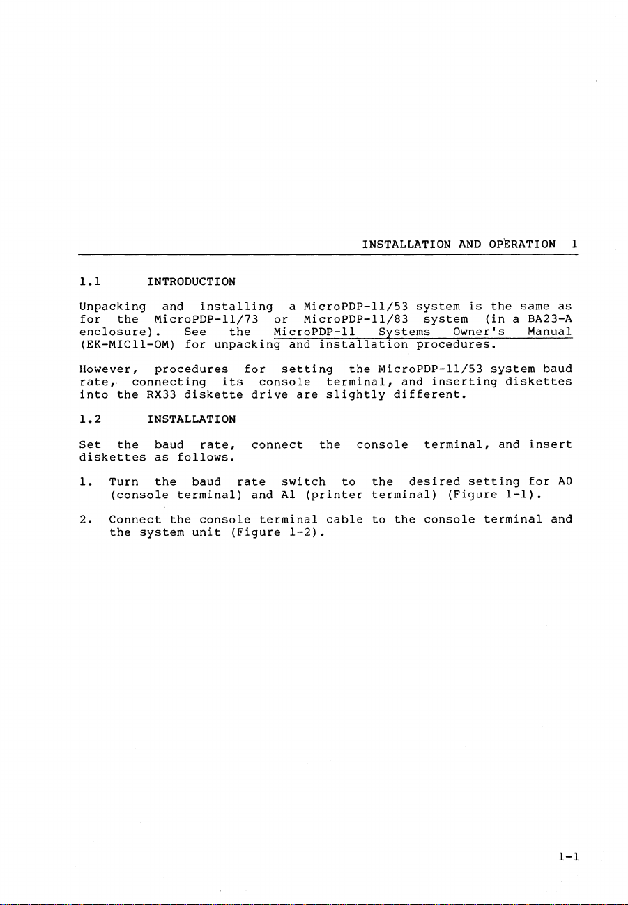
1.
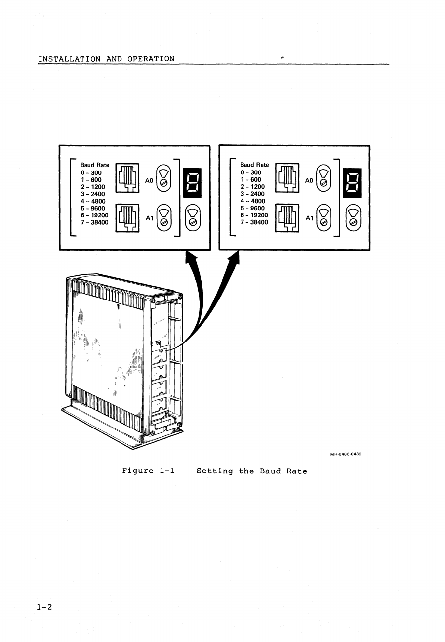
2.
INTRODUCTION
the
connecting
the
RX33
INSTALLATION
the
Turn
(console
Connect
the
system
MicroPDP-ll/73
procedures
baud
as
the
and
See
for
diskette
follows.
terminal)
the
installing
unpacking
its
rate,
baud
console
unit
the
for
drive
connect
rate
and
(Figure
a
MicroPDP-ll/53
or
MicroPDP-ll/83
MicroPDP-ll
and
setting
console
are
switch
Al
terminal
1-2).
installation
terminal,
slightly
the
to
(printer
cable
Systems
the
MicroPDP-ll/53
different.
console
the
terminal)
to
the
system
system
procedures.
and
inserting
terminal,
desired
console
is
Owner's
setting
(Figure
the
same
(in
a BA23-A
system
diskettes
and
1-1).
terminal
as
Manual
baud
insert
for
AD
and
1-1
INSTALLATION
AND
OPERATION
Baud Rate
0-300
1-
600
2 - 1200
3 - 2400
4 --4800 4 --4800
5 - 9600
6 - 19200 6 - 19200
7 - 38400
IAO®
[lA1®
III
®
Baud Rate
0-300
1-
600
2 - 1200
3 - 2400
5 - 9600
7 - 38400
mJAO®
[lA1®
III
®
1-2
Figure
1-1
Setting
the
Baud
MR-0486-0439
Rate
INSTALLATION
AND
OPERATION
VT220
(RSW)
MOOIFIEDi ,
MODULAR
JACKS
[
dadllb
0-30(1
~"'"
...
~
'_'00
2_1200
3-2400
4-·4800
5-9600
6-19200
7-38400
, ,
_____
- -
___
Q
®]
AO
'"
lEI
A,rQ)
rQ)
~
~
VT240
(REAR
VIEW) VT100
r---------1
(;S;;;'~L
L,. __________
(Rn)
~
)
Figure
1-2
Connecting
the
Console
Terminal
1-3

INSTALLATION
3.
Plug
in
4.
Thread
5.
Replace
NOTE
Do
not
turn
6.
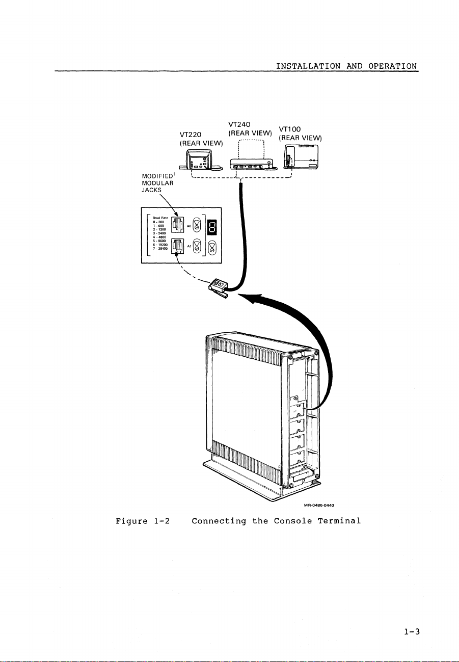
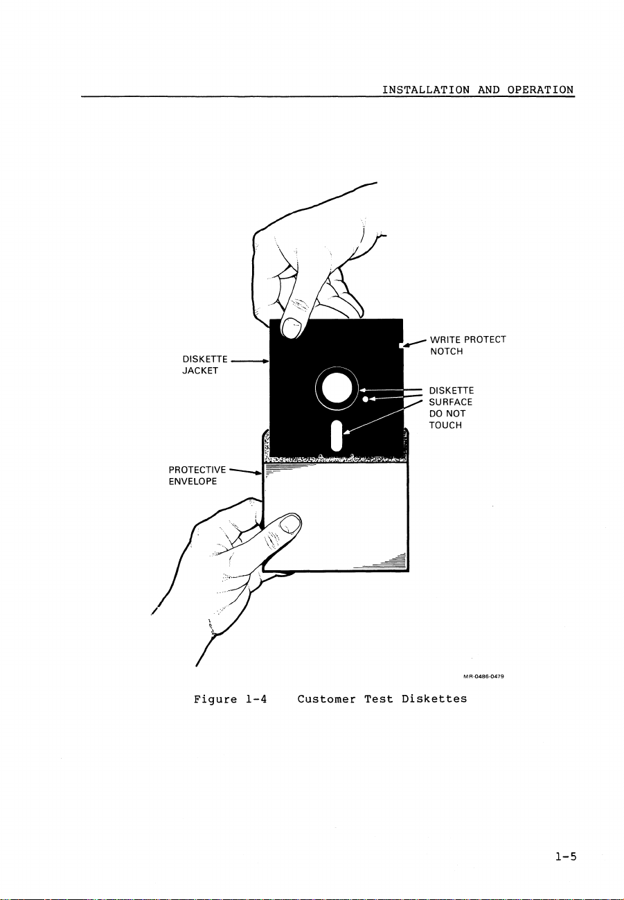
Find
the
diskette
AND
the
all
the
on
labeled
OPERATION
power
the
cables
cover.
your
system
customer
as
cord
follows.
(Figure
through
yet.
test
1-3).
the
diskettes
lower
cable
(Figure
guide.
1-4)
and
use
the
Micro-II
Cust
Figure
RXnn A
1-3
Plugging
in
the
Power
MR-13465
Cord
1-4
PROTECTIVE
ENVELOPE
INSTALLATION
WRITE
NOTCH
DISKETTE
SURFACE
DO
NOT
TOUCH
AND
PROTECT
OPERATION
Figure
1-4
Customer
Test
MA-04B6-0479
Diskettes
1-5

INSTALLATION
7.
Put
the
insert
position
NOTE
The
write
insert
notch
tabletop
a
must
system.
AND
diskette
the
(Figure
protect
diskette
be
OPERATION
drive's
diskette,
1-5).
notch
into
on
the
and
must
a
left
release
place
be
floorstand
when
you
the
in
lever
release
the
(or
insert
in
down
pedestal)
the
the
lever
position
diskette
up
position,
in
system.
the
when
into
down
you
The
a
1-6
Figure
1-5
Inserting
the
Diskette

8.
Set
the
power
switch
to 1 (on).
INSTALLATION
AND
OPERATION
In
a
following
Loading
This
several
MSCP
few
wi
is
minutes
message.
MICRO-ll
II
take a few
minutes
the
Diagnostic/Boot
the
Customer
if
running
seconds
console
Diagnostic
if
from
Device.
running
Tape.
terminal
Operating
from
Please
will
System-V12.0
Disk
or
wait
•••••••
display
the
M
A-0586-Q725
1-7

INSTALLATION
AND
OPERATION
Next,
the
the
screen.
following
CUSTOMER
T - Run
F -
Type
the
Customer
DIAGNOSTICS -
Identify
Go
letter
System
to
System
the
then
V12.0 -Main
Tests.
Format
press
Diagnostics
Devices.
Menu.
the
RETURN
Menu
key
Menu
••••••••
is
displayed
MA-0586-0726
on
9.
Follow
Now
you
instructions
1-8
the
can
instructions
install
provided
with
your
displayed
software
your
software.
on
the
(Figure
Main
Menu.
1-6).
Follow
the

Figure
1-6
Customer
INSTALLATION
MR-13472
Software
AND
OPERATION
1.3
To
operate
Owner's
When
control
front
has
two
The
second
two
RD3n
these
When
self-test.
will
Manual
reading
panel.
write
buttons,
you
try
OPERATION
your
MicroPDP-llj53
(EK-MIC1I-OM).
the
panel
shown
The
protect
set
fixed
of
disk
see
turn
If
to
the
boot
owner's
is
different
MicroPDP-llj53
and
two
write
drives
protect
are
Paragraph
the
power
start-up
the
storage
system,
manual,
uses a 6-button
ready
and
installed
2.2.3
on,
in
the
self-test
media.
see
you
will
from
buttons.
ready
this
system
the
MicroPDP-ll
notice
the
MicroPDP-llj53
buttons
in
the
manual.
will
is
successful,
that
control
function
system.
run
its
the
panel
To
start-up
the
Systems
front
system
that
only
disable
system
if
1-9


MicroPDP-ll/53
Enclosure
2
2.1
The
(Figure
INTRODUCTION
MicroPDP-ll/53
2-1).
MicroPDP-ll/73,
The
BA23-A
assembly.
half-height
front
control
fans.
enclosure
It
also
or
two
panel,
system
The
enclosure
and
MicroPDP-ll/83
provides
5.25-inch
the
Figure
houses
rear
2-1
is
housed
is
the
system
the
mounting
full-height
I/O
distribution
BA23-A
same
power
POWER
Enclosure
in
the
as
the
enclosures.
supply
space
mass
for
storage
SUPPLY
BA23-A
MicroPDP-ll/23,
and
the
three
devices,
panel,
and
MA-04BS-0412
enclosure
backplane
5.25-inch
the
cooling
2-1

MicroPDP-ll/53
The
enclosure
rack-mounted
for
tabletop
the
various
ENCLOSURE
can
in
use.
models.
a
cabinet.
be
Table
housed
The
2-1
either
floorstand
shows
in a plastic
the
dimensions
model
floor-stand
can
be
and
converted
weights
or
of
Table
Height
Width
Depth
Weight
2.2
The
BA23-A
6-button
two
half-height
switches
Table
indicators
2-1
MicroPDP-ll/53
FRONT
and
2-2
CONTROL
enclosure
panel.
indicators
describes
functions.
Fixed Disk 1 Fixed Disk 0
Write
Protect
G
Floorstand
64.2
(24.5
25.4
(10
72.6
(28.6
31.
(70
The
6-button
fixed
Write
G
cm
in)
cm
in)
cm
in)
75
kg
Ib)
PANEL
front
disk
for
the
Protect
Dimensions
control
control
drives.
monitoring
front
Halt
G
and
Tabletop
17.7
cm
(7
in)
56.2
cm
(22.13
72.6
cm
(28.6
29.5
kg
(65
Ib)
panel
panel
The
and
control
Run
0
Weights
Rackmount
13.3
(5.2
48.25
(19
in)
in)
(Figure
allows
control
controlling
panel
64.3
(25.3
24 kg
(53
for
panel
switches
in)
Ib)
mamaama
Micro
PDP-ll/53
cm
in)
cm
cm
in)
2-2)
the
the
is
use
contains
system.
a
of
and
2-2
Figure
Ready
G
2-2
Ready
G
BA23-A
Restart
G
Enclosure
DeOK
0
Front
0
Control
--
MA-0486-0413
Panel

MicroPDP-ll/53
ENCLOSURE
Table
Switches
On/off
Halt
Restart
Write
2-2
protect
Front
DC
Run
Halt
Wr i te
Control
Indicators
OK
protect
Panel
Switches
Function
Rocker
indicator
when
system
Green
voltages
tolerance.
Green
is
executing
Push-on/push-off
the
CPU
Red
has
halted.
Contact
pressed,
power-down/power-up
restart
Push-on/push-off
disk
switch
Amber
the
fixed
switch
light
light
when
light
the
is
is
light
and
Indicators
with
red
ac
power
comes
are
present
comes
in
pushed
comes
pushbutton
causes
CPU.
write
pushed
comes
disk
is
the
switch
switch
in.
write
integral
light
is
on.
on
and
on
when
run
mode.
in.
on
when
switch
a
sequence
protected
on
to
protected.
comes
when
within
the
--
halts
the
--
when
simulated
fixed
when
indicate
red
on
dc
CPU
CPU
to
Ready*
*
With
of
write
control
two
panel
Ready
half-height
protect
(6-button
and
fixed
ready
panel).
Push-on/push-off
read
switch
disk
is
Green
the
fixed
The
fixed
disk
drives
switches
or
is
off-line.
light
are
write
pushed
comes
disk
disk
installed,
functional
to
is
switch
fixed
in.
on
can
be
on-line.
the
at
-disk
The
to
indicate
accessed.
second
the
cannot
when
fixed
set
front
2-3

MicroPDP-ll/53
ENCLOSURE
2.2.1
The
control
plastic
V
and
clock
jumpers
The
printed
LEOs,
cable.
on/off
2.2.2
The
LTC
labeled
Q22-Bus
software
Control
front
+12
V
(LTC)
WI,
W2,
circuit
and
a
A
bracket
(I/O)
switch.
LTC
DIP
DIP
1
and 2 (Figure
BEVNT
control.
0
~W3
I
I
1
Panel
panel
control
test
switch
and
20-pin
on
Switch
(dual
timing
PC
'0'"0,
Printed
printed
panel.
points.
unit,
W3.
board
connector
back
Unit
in-line
signal
Switch
TEST
D~
also
of
2-3).
1
is
Circuit
circuit
This
It
also
to
the
contains
the
front
package)
Setting
and
called
'""""
'~""""'
"'0
0
+ +
01-
board
provides
restart
(Jl)
lets
the
Board
board
provides
the
for
panel
switch
switch
BEVNT
~
'"
I
I
I
is
access
enable
control
the
backplane
holds
unit
1
to
the
LTC
Enable
LTC SWITCH
behind
access
to a line
switch,
panel
the
has
off
function
the
to
assembly
system
two
switches
enables
switch.
molded
the
time
and
buttons,
power
under
+5
to
the
2-4
I Fisked Disk 1 Fixed Disk 0
I Write Protect
IGJ
I
Write Protect
G
I
Ready
I
fl~G
I 0
I
Ready
G
I
I
L
Figure
___
(=[
l
2-3
,..,
Control
Halt
G
G
o 0 1
W10
1\
\
Panel
I
Run
i
0
I
I
I
DC
OK I
~I
I
o 1
1
I
_J
,
and
Printed
mamaama
Micro
PDP-ll/53
0
20-PIN
CONNECTOR
ON
PC
BOARD
Circuit
.....-
--
/--
MR-0486-0414
Board
POWER
ON/OFF
SWITCH

MicroPDP-ll/53
ENCLOSURE
Setting
panel
the
restart
Restart/Enable
restart
the
on
position.
2.2.3
The
control
following
WI
--
You
is
in
W2 --You
is
is
W3 --This
ensure
B
NOTE
The
factory
Figure
If
an
should
The
2-4.
and
set
be
W3
jumper
For
2
so C and 1 are
switch
switch.
Jumpers
three
can
inoperative
the
BA23-A
can
inoperative
located
jumper
DC
OK H signal
2-4.
RD3n
set
the
are
tied
2
(Restart/Enable)
switch
function
switch
The
Restart/Enable
WI,
W2,
panel
printed
jumpers.
set
this
(see
enclosure.
set
this
(see
piggybacked
is
that
DC
OK
(see
configurations
Both
RDO
drive
C)
printed
and
so
expansion
disk
(1
on
BA23-C
to
the
together.
tied
to
and
W3
jumper
note).
jumper
note).
on
used
LED
is
note).
RDI
is
not
the
circuit
For
together.
as
off
disables
circuit
so
RDO
so
the
in
a BA23-C
directly
(2
Write
present,
LED
enclosure,
the
to
described
switch
the
RDO
is
the
RDI
RDl,
the
first
to
C)
Protect
is
inoperative.
board
BA23-A
on
lets
in
the
should
board
Write
the
first
Write
second
RD3n
expansion
controlled
for
WI
switches
the
associated
is
the
enclosure,
Table
front
also
Protect
Protect
drive.
and
also
jumper
the
RD3n
RD3n
W2
shown
front
2-2.
control
normally
contains
switch
disk
switch
disk
enclosure
by
the
are
are
LED
in
is
the
jumper
control
Setting
panel
be
the
LED
drive
LED
drive,
Q22-Bus
shown
enabled.
jumper
Figure
set
so
in
to
in
C
is
RDO
2
DRIVE
C
PRESENT
2 C
RDl
NO
Figure
DRIVE
2-4
PRESENT
Jumper
2
FOR BA23-A
ENCLOSURE
WI,
W2,
C
and
W3
C
2
FOR BA23-C
EXPANSION
ENCLOSURE
MA-0486-0481
2-5

MicroPDP-ll/53
The
following
the
top
pin,
ENCLOSURE
jumper
C
is
the
settings
center
pin,
are
possible.
and 1 is
the
(In
bottom
figure
pin.)
2-4 2 is
WI
2
C
W2
2
storage
C
2
W3
C
2.3
The
front
devices.
RX33
tape
drive
The
bottom
fixed
NOTE
Two
half-height
style)
2.4
The
MicroPDP-ll/53
as
other
major
and
the
and
C
1
C
area.
1
C
1
STORAGE
bezel
diskette
or
an
(or
drive.
drive
no
drive
drive
panel
panel
cover
top
(or
RX50
left)
This
fixed
O.
system
are
backplane.
and
and
and
and
and
MASS
The
dual
disk
in
port
BACKPLANE ASSEMBLY
MicroPDP-ll
components
Q22-Bus
RDO
drive
RDI
is
is
drive.
diskette
systems
present.
installed
installed
right)
space
space
disk
the
present
is
RDI
is
not
spaces
This
is
uses
mass
is
present
present
space
space
drive.
usually
called
drives
the
(Figure
storage
are
in
mass
(piggybacked)
BA23-C
in
a
in a BA23-A
for
can
also
space
contains
port
can
be
backplane
signal
mounting
contains
The
usually
This
same
2-5).
storage
expansion
enclosure.
accommodate
a
O.
installed
backplane
distribution
area.
mass
a
is
called
half-height
assembly
in
the
box.
storage
half-height
a TK50
port
(piggyback
(H9278)
assembly
panel
mass
1.
RD3n
2-6

@
J2
Assembly
Panel)
J1
(NOT
LABELED)
..
~
•••
m·
J7
J10
•
•
J8
:::
()
1""'\
o
'0
a
'0
I
,....
,....
"-
I.J1
W
C':l
Z
o
r
o
[Jl
C
:0
C':l
J3 ,
...
,:....:....:..;,
,
@
J6
J1
FIXED DISK 1
11:::::::::::::::::::::11 11::::::::::::::11
J7
FIXED DISK 0
II:::::::::::::::::::::U
J2
FIXED
DISK 0
@
Figure
REMOVABLE
II
::::::::::::::::::::11
I
L_J'
2-5
(Showing
I'V
I
-.]
.....
------------'""\
DISK
H9278
the
Distribution
1+2
J5
FIXED DISK 1
1i::::::::::::::11
Backplane

MicroPDP-ll/53
ENCLOSURE
2.4.1
The
diskette
enclosure,
Figure
enclosure.
Mass
Storage
drive
connect
2-6
shows
SIGNAL
DISTRIBUTION
J7
J3
PANEL
Distribution
and
fixed
to
the
the
internal
POWER
SUPPLY
UNIT
mass
disk
storage
Panel
drive,
cabling
REAR
installed
signal
FAN
distribution
setup
for
in
the
the
BA23-A
panel.
BA23-A
2-8
°0
RD31
Figure
2-6
RX33
BA23-A
Enclosure
FRONT
CONTROL
PANEL
Internal
M
R-0486-0415
Cabling

The
signal
controller
connectors
functions.
J6
Removable
diskette
code
labels
NOTE
When
two
labels
J7
Fixed
RD3n
This
ROM
Jl
disk
is
code
Fixed
second
drive.
system
distribution
module
on
drive.
the
RD3n
the
RX33
Disk 0 and
drive
the
labels
Disk
RD3n
disk
This
ROM
code
the
signal
Disk
1
With a fixed
RX33
diskette
disk
diskette
J2
installed
first
it
1
fixed
disk
and
drive
is
the
second
labels
panel
installed
distribution
and
drives
drive
Fixed
in
disk
unit
J5
Fixed
installed
it
disk
carries
in
2
disk
drive
are
as
disk
Disk 0 --
port 0 of
drive
0 (DUO).
Disk 1 --
piggyback
fixed
disk
unit
the
panel
provide
drive
as
disk
installed,
unit
provide
to
drive
1
(DUl).
MicroPDP-II/53
the
signals
Q22-Bus
provide
the
signals
installed,
unit
the
2
(DU2).
the
the
enclosure
be
booted,
provide
on
the
to
be
from
backplane.
the
the
1
(DUl).
system
signals
and
the
first
booted,
ENCLOSURE
an
following
to
system
ROM
(left
the
signals
fixed
RQDX3
an
to
slot).
system
and
Six
RX33
ROM
code
to
disk
the
a
a
J4
board
from
2.4.2
The
MicroPDP-ll/53
assembly
addressing
commonly
The
backplane,
ac
loads
backplane.
module
picofarads
module
105
microamperes
six
ac
The
four
provide
Jl
supply
J2
control
provides
the
Q22-BuS
that
called
and
presents
(pF).
presents
loads
connectors
the
is
power
is
panel
mass
Backplane
implements
to
support
the
driven
20
The
ac
The
to a bus
«
56
following
an
IS-pin
and
signals
a
lO-pin
from
the
storage
system
Q22-Bus.
dc
loading
to
dc
(uA).
pF)
the
signals
the
up
by
the
loads
a
bus
loading
signal
The
and
no
on
side
functions.
straight
to
connector
CPU
module
to
the
signal
control
distribution
backplane
extended
to 4 megabytes
MicroPDP-ll/53
from
all
is
the
the
loads
2
amount
line;
one
itself
(Figure
signal
is
line;
backplane
dc
single
the
backplane
that
provides
(KDJll-DA).
is a 10.7
LSI-bus,
of
CPU,
modules
one
amount
dc
on
any
in-line
from
panel
printed
panel.
inch
by
which
memory.
supports
inserted
of
capacitance
ac
of
dc
load
load
leakage
is
4.5
uses
This
up
in
equals
approximately
contributes less
signal
2-4)
of
line.
the
backplane
connector
the
power
signals
to
supply.
the
circuit
inch
22-bit
bus
to
the
that
9.35
that
than
used
front
is
22
Q22
a
a
to
2-9

MicroPDP-ll/53
J3
and
J4
termination
storage
For
fans,
device
more
see
ENCLOSURE
for
is
information
the
MicroPDP-ll
are
the
present.
4-pin
mass
on
Mate-n-Lock
storage
the
system
Systems
device
backplane,
Technical
connectors
power
cable
Manual
that
when
power
supply,
(EK-MICII-TM).
provide
no
mass
and
2.5
External
rear
I/O
Each
module
internal
these
The
three
filter
panels
panel.
for
up
connectors.
Figure
insert
panel
console
installed
REAR
I/O
devices
distribution
that
cable,
items
connectors
are
installed
The
enclosure's
to
six
2-7
shows
installed.
display
in
the
CONSOLE SLU
INSERT-OISPLAY
PANEL
A
DISTRIBUTION
connect
panel.
connects
a
filter
are
called
insert
the
panel
top
of
(or
!
I
to
connector,
a
mount
in
cutouts
rear
I/O
panels,
rear
I/O
Figure
the
KDJIl-DA
left)
PANEL
the
to
an
cable
in
the
distribution
distribution
2-7
cutout.
system
external
and
kit.
in
two
also
an
insert
of
shows
CPU
through
insert
panels
the
rear
which
module,
device
panel
can
panel
the
REMOVABLE
INSERT
the
enclosure's
comes
panel.
and
I/O
with
Together,
the
distribution
provides
contain
with a typical
serial
which
line
is
METAL
insert
space
50
pin
unit
usually
an
2-10
o E
Figure
2-7
50-PIN
EXPANSION SLOTS
Rear
I/O
o F
CONNECTOR
Distribution
o
MR-0486-0416
Panel

MicroPDP-ll/53
BASE
SYSTEM
3
1.1
:his
chapter
lescribes
KDJll-DA
Automatic
Console
Test
3.2
rhe
MicroPDP-ll/53
(M7554)
:ontroller
jrives.
~OTE
The
MSVll-QA/QB
expansion
The
MicroPDP-ll/53
interconnect
module
and
INTRODUCTION
identifies
the
following.
CPU
module
boot
mode
code
error
SYSTEM
with
IDENTIFICATION
onboard
module
Expansion
memory
modules
(private
expansion
mode
messages
base
(M7555)
memory
and
memory
memory
the
system
memory.
to
modules
MSVll-PL/PK
for
the
system
does
interconnect,
module(s).
MicroPDP-ll/53
contains
The
system
support
may
also
the
be
(M755l-AA/AB
MicroPDP-ll/53
not
or
a
KDJll-DA
also
RX33
present.
and
system.
provide
PMI)
base
contains
and
M8067-L/K)
a
between
system
CPU
module
an
RD3n
high-speed
the
and
RQDX3
disk
are
CPU
3-1

MicroPDP-ll/53
BASE
SYSTEM
3.3
The
KDJII-DA
operates
standard
•
PDP-II
(EIS)
•
Memory
•
512
•
32
•
Line
•
Console
unit
•
DCJll
NOTE
Instruction
the
DCJll
Figure
on
the
factory
Table
3-1
KDJII-DA
is a quad-height
at
15
features.
instruction
and
floating
management
kilobytes
kilobytes
frequency
serial
CPU
chip
set
Microprocessor
3-1
shows
CPU
settings.
module.
KDJII-DA
CPU
MODULE
MHz.
point
of
local
of
boot
clock
line
set
differences
the
location
Table
Switch
The
set,
and
unit
User's
Q22-Bus
KDJII-DA
including
instruction
(onboard)
diagnostic
(SLU)
for
Guide,
of
switches,
3-1
and
Jumper
PDP-II
CPU
module
extended
set
parity
ROM
and a printer
the
Jll
processors
Appendix
lists
the
Factory
processor
has
(FPll)
memory
port
C
(EK-DCJII-UG).
connectors,
switches
Settings
module
the
following
instruction
serial
are
listed
and
and
that
set
line
in
jumpers
jumpers
Switches
Boot
mode
select
Baud
rate
Baud
rate
Jumper
WI
Wll
W20
W21
NOTE
Jumpers
MicroPDP-II/53
to
KDJII-DA
3-2
W2
control
internal
Description
Directs
execution
SLU
SLU I (AI)
Description
Trap
SLU 0 halt
BIAK
BDMG
through
console
baud
0
on
CM2
CR2
WIO
rates
cabling.
bootstrap
(AO)
kernel
and
display
and
on
CN2
CS2
boot
halt
break
Wl2
panel
selections.
MUST
rotary
Ship
Position
Position
Position
Function
Disabled
Enabled
Enabled
Enabled
be
switches
Figure
Configuration
OUT
to
3-3
0
5
9600
5
9600
Position
In
Out
In
In
allow
(Figure
shows
baud
baud
the
3-2)
the

W3
WS
••••
••••
W5
W2
W22
-
MicroPDP-11/53
Wl0
••
W7
W12·
•
••
• • W6
•
• • W9
.W4
BASE
SYSTEM
DOD
I I I I I I I I I
I I I I I I I I I
W21
--
Figure
SLU 0 BAUD RATE
CONNECTOR SELECT
(CONSOLE
3-1
TERMINALI
SLU 0
SWITCH
1
W20
00
Wl
-
1
KDJ11-DA
Module
TEST
DISPLAY
Wll
-
Layout
CODE
Figure
SLU 1 SLU 1
CONNECTOR BAUD RATE
3-2
MicroPDP-11/53
SELECT SWITCH
16 POSITION SWITCH
(BOOT MODE SELECT)
Console
Display
Panel
3-3
 Loading...