

Page 1

plus
LG
Series
Text and Graphics Printer
TM
Operator’s Guide
Order Number: EK–LGPLE–OG, Rev. A
Digital Equipment Corporation
Page 2

FCC Notice
This equipment has been tested and found to comply with the limits of a Class A
digital device, pursuant to Part 15 of the FCC Rules. These limits are designed to
provide a reasonable protection against harmful interference when the equipment
is operated in a commercial environment. This equipment generates, uses, and
can radiate radio frequency energy and, if not installed and used in accordance
with the instruction manual, may cause harmful interference to radio
communications.
Operation of this equipment in a residential area is likely to cause harmful
interference, in which case the user will be required to correct the interference at
his own expense.
Any changes or modifications not expressly approved by the manufacturer could
void the user’s authority to operate the equipment.
Installing this equipment in an FCC Level B product results in an FCC Level A
Composite System as defined in the FCC Rules and Regulations.
Canadian Department of Communications compliance statement:
This equipment does not exceed Class A limits per radio noise emissions for
digital apparatus as set out in the Radio Interference Regulation of the Canadian
Department of Communications. Operation in a residential area may cause
unacceptable interference to radio and TV reception requiring the owner or
operator to take whatever steps are necessary to correct the interference.
Avis de conformite aux normes du ministere des
Communications du Canada:
Cet equipment ne depasse pas les limites de Classe A d’emission de bruits
radioelectriques pour les appareils numerriques tells que perscrites par le
Reglement sur le brouillage radioelectriques etabli par le ministere des
Communications du Canada. L’exploitation faite en milieu residentiel peut
entrainer le brouillage des receptions radio et tele, ce qui obligerait le proprietaire
ou l’operateur a prendre les dispositions necessarires pour en eliminer les cause.
Page 3

notices
European Directive.
This product is in conformity with the protection requirements of the EC Council
Directive 89/336/EEC on the approximation of the Laws of the Member States
relating to electromagnetic compatibility .
All Rights Reserved. December 1995.
Digital Equipment Corporation makes no representations that the use of its
products in the manner described in this publication will not infringe on existing or
future patent rights, nor do the descriptions contained in this publication imply the
granting of licenses to make, use, or sell equipment or software in accordance
with the description.
Possession, use, or copying of the software described in this publication is
authorized only pursuant to a valid written license from Digital or an authorized
sublicensor.
Digital Equipment Corporation 1995. Printed in U.S.A.
Page 4

Trademarks and Service Marks
The following are trademarks of Digital Equipment Corporation: DEClaser,
DECnet, DECserver, OpenVMS, PrintServer, ThinWire, ULTRIX, VAX, and the
DIGITAL logo.
PostScript
registered in certain jurisdictions. AppleTalk, LocalTalk, LaserWriter, and
Macintosh are registered trademarks of Apple Computer, Inc. Microsoft, MS,
MS–DOS, and Windows NT are registered trademarks of Microsoft Corporation.
Centronics is a trademark of Centronics Data Computer Corporation. IBM is a
registered trademark and IBM PC/A T is a trademark of International Business
Machines Corporation.
All other trademarks and registered trademarks are the property of their
respective holders.
TM
is a trademark of Adobe Systems Incorporated, which may be
Page 5

About this Operator's Guide
Digital wants you to feel comfortable
using the LG
guide. This book has been designed to
meet the needs of all users, from
beginners to those experienced with line
matrix printers.
Follow the directions in this guide along
with those in your
avoid injury to you and damage to the
printer.
This guide is divided into three sections:
Basic Operating Procedures — gives an
overview of the control panel and provides
procedures for loading paper and ribbon.
Configuration — provides procedures for
using the control panel to save, modify , and
delete configurations.
Troubleshooting — gives instructions
for clearing paper jams, cleaning
components, and troubleshooting.
plus
Series Printer and this
Setup Guide
in order to
LG
plus
Series Printer
Page 6

about this operator's guide
Conventions
Warnings, Cautions, and Notes
Warnings provide information about
conditions that could harm you or damage
the printer.
Cautions provide information about
conditions that could damage the printer.
Notes provide supplemental information
that could affect printer operation or use.
Message Display
These boxes show display messages as
they appear on the printer.
OFFLINE
CONFIG. CONTROL
Page 7

Table of Contents
BASIC OPERATING PROCEDURES
Powering On the Printer 2. . . . . . . . . . . . . . . . . . . . . . . . . . . . . . . . . . . . . . . . . . . .
Using the Control Panel 4. . . . . . . . . . . . . . . . . . . . . . . . . . . . . . . . . . . . . . . . . . . .
Loading Paper 19. . . . . . . . . . . . . . . . . . . . . . . . . . . . . . . . . . . . . . . . . . . . . . . . . . .
Setting Top-of-Form 23. . . . . . . . . . . . . . . . . . . . . . . . . . . . . . . . . . . . . . . . . . . . . . .
Reloading Paper 26. . . . . . . . . . . . . . . . . . . . . . . . . . . . . . . . . . . . . . . . . . . . . . . . .
Unloading Paper 30. . . . . . . . . . . . . . . . . . . . . . . . . . . . . . . . . . . . . . . . . . . . . . . . .
Replacing the Ribbon 32. . . . . . . . . . . . . . . . . . . . . . . . . . . . . . . . . . . . . . . . . . . . .
Canceling a Print Job 36. . . . . . . . . . . . . . . . . . . . . . . . . . . . . . . . . . . . . . . . . . . . .
CONFIGURATION
Configurations and Parameters 38. . . . . . . . . . . . . . . . . . . . . . . . . . . . . . . . . . . . .
Saving Configurations 44. . . . . . . . . . . . . . . . . . . . . . . . . . . . . . . . . . . . . . . . . . . . .
Printing Configurations 46. . . . . . . . . . . . . . . . . . . . . . . . . . . . . . . . . . . . . . . . . . . .
Loading Configurations 48. . . . . . . . . . . . . . . . . . . . . . . . . . . . . . . . . . . . . . . . . . . .
Deleting Configurations 50. . . . . . . . . . . . . . . . . . . . . . . . . . . . . . . . . . . . . . . . . . . .
The Power–Up Configuration 52. . . . . . . . . . . . . . . . . . . . . . . . . . . . . . . . . . . . . . .
TROUBLESHOOTING
Clearing Paper Jams 56. . . . . . . . . . . . . . . . . . . . . . . . . . . . . . . . . . . . . . . . . . . . .
Cleaning the Printer 59. . . . . . . . . . . . . . . . . . . . . . . . . . . . . . . . . . . . . . . . . . . . . .
Solving Print Quality Problems 62. . . . . . . . . . . . . . . . . . . . . . . . . . . . . . . . . . . . .
Fault Messages 64. . . . . . . . . . . . . . . . . . . . . . . . . . . . . . . . . . . . . . . . . . . . . . . . . .
T able of Contents
i
Page 8

ii T able of Contents
Page 9

BASIC OPERATING PROCEDURES
♦ Powering on the Printer 2
♦ Using the Control Panel 4
♦ Loading Paper 19
♦ Setting Top-of-Form 23
♦ Reloading Paper 26
♦ Unloading Paper 30
♦ Replacing the Ribbon 32
♦ Canceling a Print Job 36
1Operator’s Guide
Page 10
Powering On the Printer
warning
Before powering on the printer, make sure
it is plugged into the appropriate power
source.
Refer to the “Select a Site” section in
Chapter 2 of the Setup Guide for
information on proper power sources.
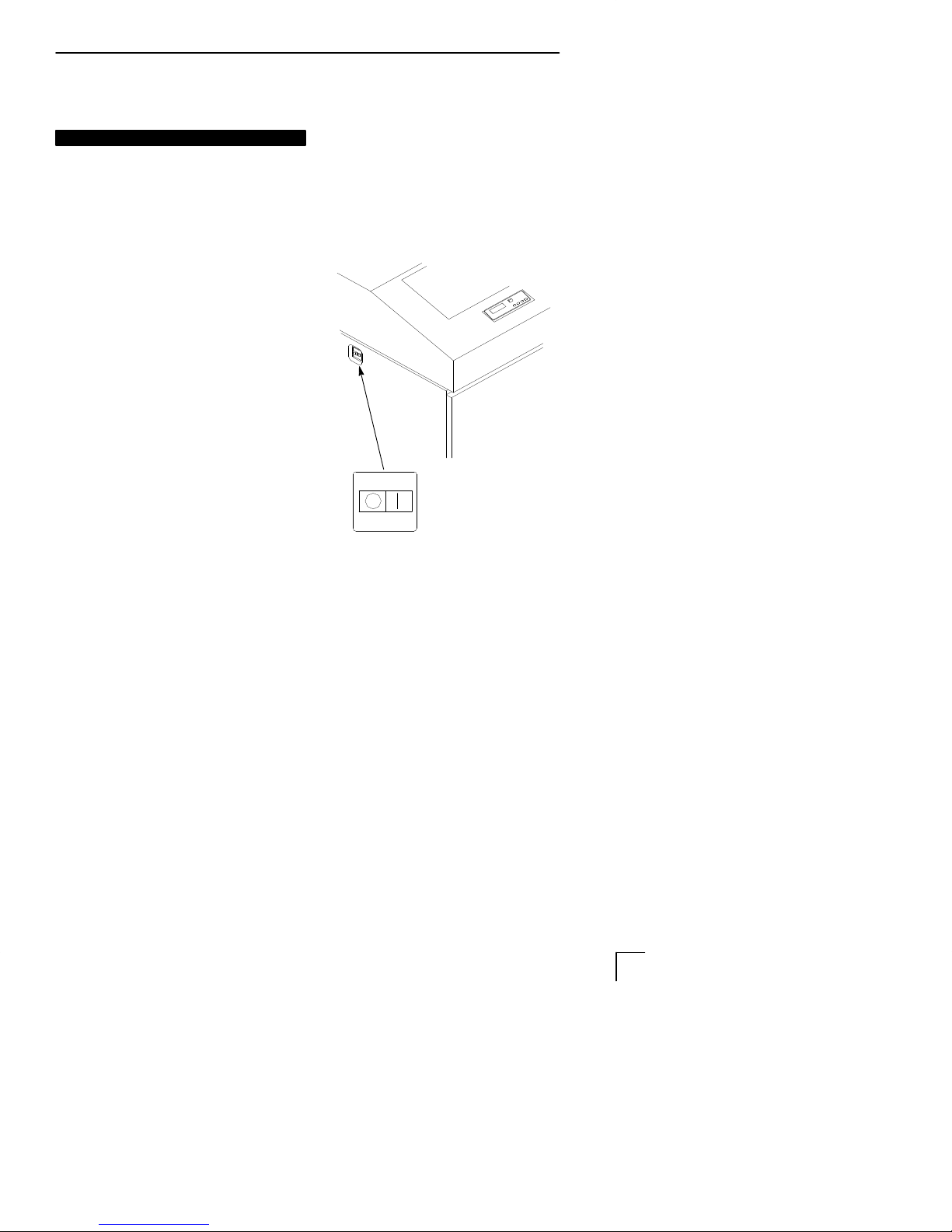
The power switch is located at the
top left side of the cabinet.
Push the On (|) switch to power on
the printer. Push the Off (O) switch
to power off the printer .
Off On
2 Operator’s Guide
Page 11
When you power on the printer,
the printer executes a
power-on self-test. The
message “Testing Hardware
Please Wait” displays. When
the self–test completes, the
message “Diagnostics Passed”
displays. Once the software
has initialized successfully, the
status indicator lights to
indicate the printer is online
and an online message
appears in the display , followed
by the name of the active
emulation (the default is LG).
If there is a fault during the
self-test, the status indicator
flashes and a specific fault
message appears on the
display (such as “LOAD
P APER”). See page 64 for
information on Fault Messages.
ONLINE
LG
LOAD PAPER
3Operator’s Guide
Page 12
Using the Control Panel
Use the control panel to perform routine
operations such as:
• Placing the printer in the online or
offline mode
• Advancing or retracting the paper, and
setting the top–of–form
• Clearing fault conditions
• Configuring the printer
• Running printer self-tests
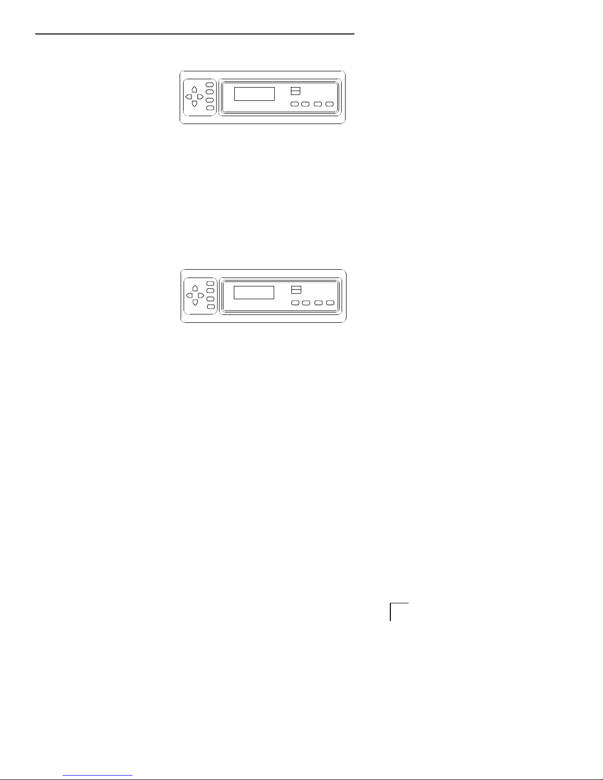
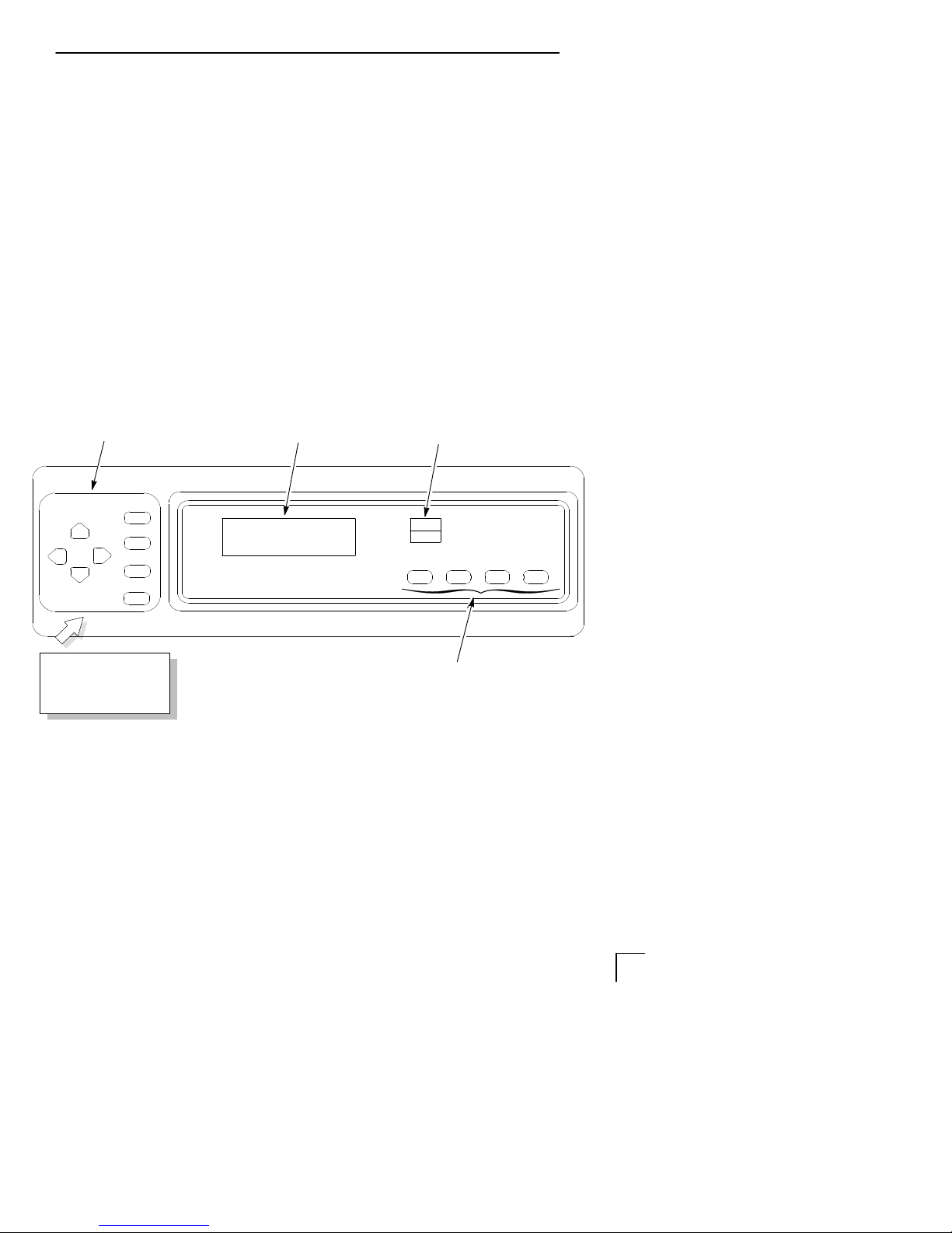
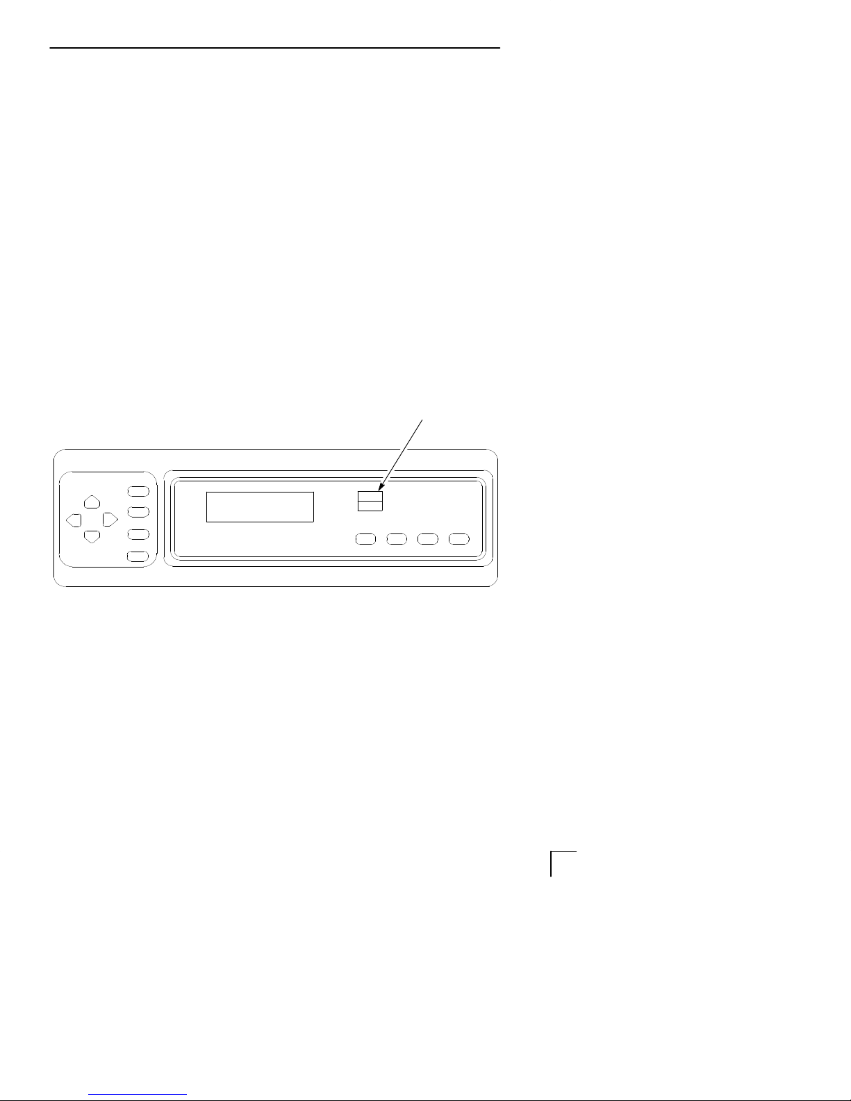
Control Panel Layout
Secondary Keys
UP
DOWN
RAISE PRINTER
COVER TO ACCESS
THESE SWITCHES
CLEAR
R/S
NEXTPREV
SET TOF
ENTER
Message Display
The printer’s operating modes, message
display , status indicator, and control panel
keys are described on the following pages.
Status Indicator
ON LINE FF VIEWLF
Primary Keys
4 Operator’s Guide
Page 13

Operating Modes
The printer operates in one of three modes,
as described below:
• Online Mode — In online mode, the printer
can receive and print data sent from the
host. Pressing the ON LINE key toggles
the printer from offline to online mode. The
status indicator is lit in online mode.
• Offline Mode — In offline mode, you may
perform operator functions, such as
loading paper and setting top-of-form. You
may also traverse the printer’s
configuration menus. Pressing the ON
LINE key toggles the printer from online to
offline mode. The status indicator is off in
offline mode.
• Fault Mode — a fault condition exists that
must be cleared before printing can
continue. In fault mode, the status indicator
is flashing, the alarm beeps three times,
and a descriptive fault message displays.
using the control panel
The current operating mode may be selected via
control panel keys, or may result from routine
operations such as powering on the printer. The
current operating mode is frequently indicated as
part of the printer display message.
5Operator’s Guide
Page 14
using the control panel
Format Conventions
Messages, keys, and indicators are shown
as they appear on the control panel. Key
combinations are indicated with the plus (+)
sign. For example, “Press CLEAR+ENTER”
means to press the CLEAR key and the
ENTER key at the same time.
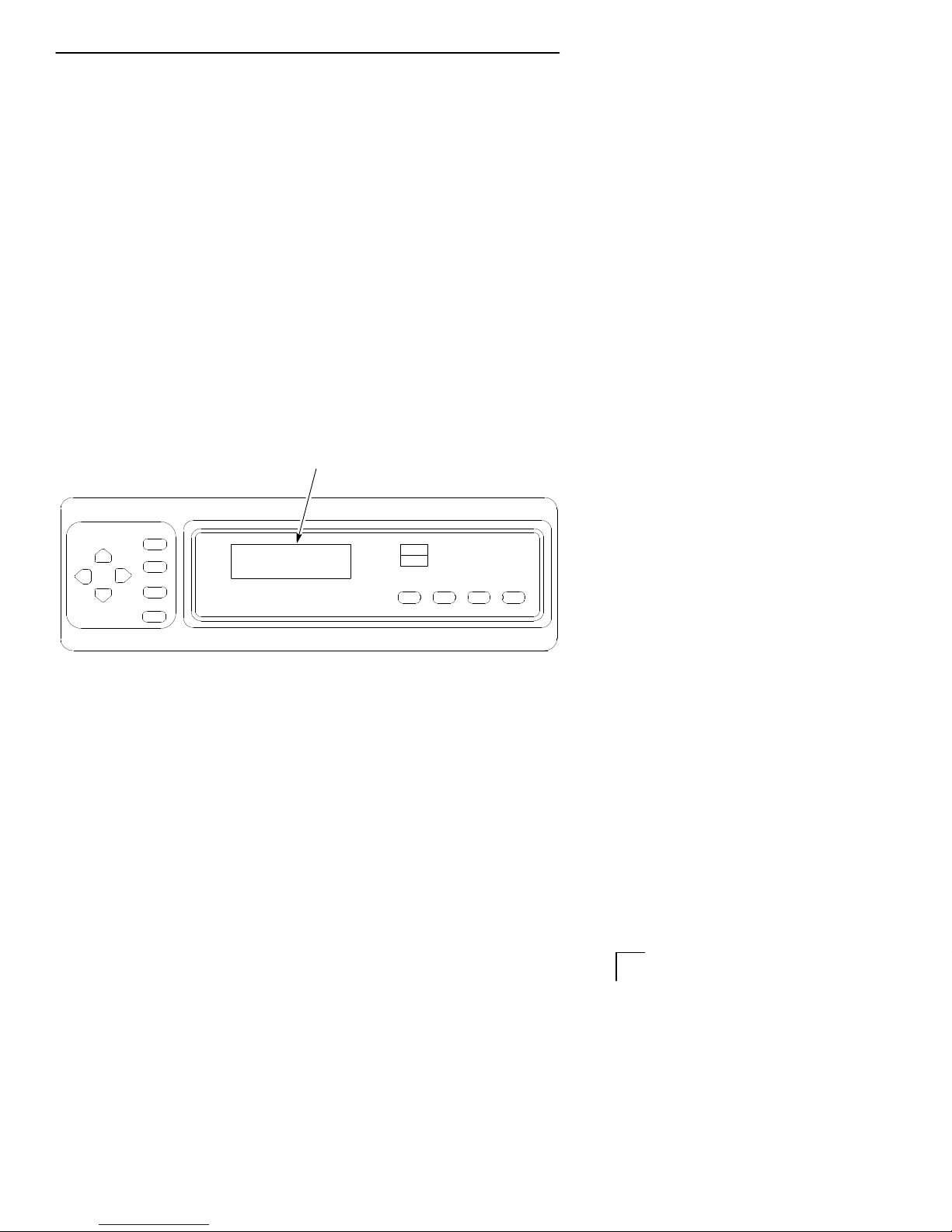
Message Display
Function Displays operating modes,
menu options, and fault
messages.
Message Display
ONLINE
LG
6 Operator’s Guide
Page 15
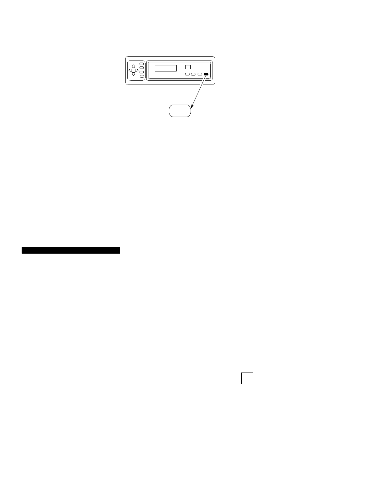
Status Indicator
The status indicator indicates the printer’s
operating mode, as follows:
•
On
— Status indicator illuminates
continuously when the printer is in
online mode.
•
Off
— Status indicator is off when the
printer is in offline mode.
•
Flashing —
fault condition exists and the printer is
in Fault mode. An error message will
generally display that describes the
error condition.
Status indicator flashes if a
using the control panel
Status Indicator
7Operator’s Guide
Page 16

using the control panel
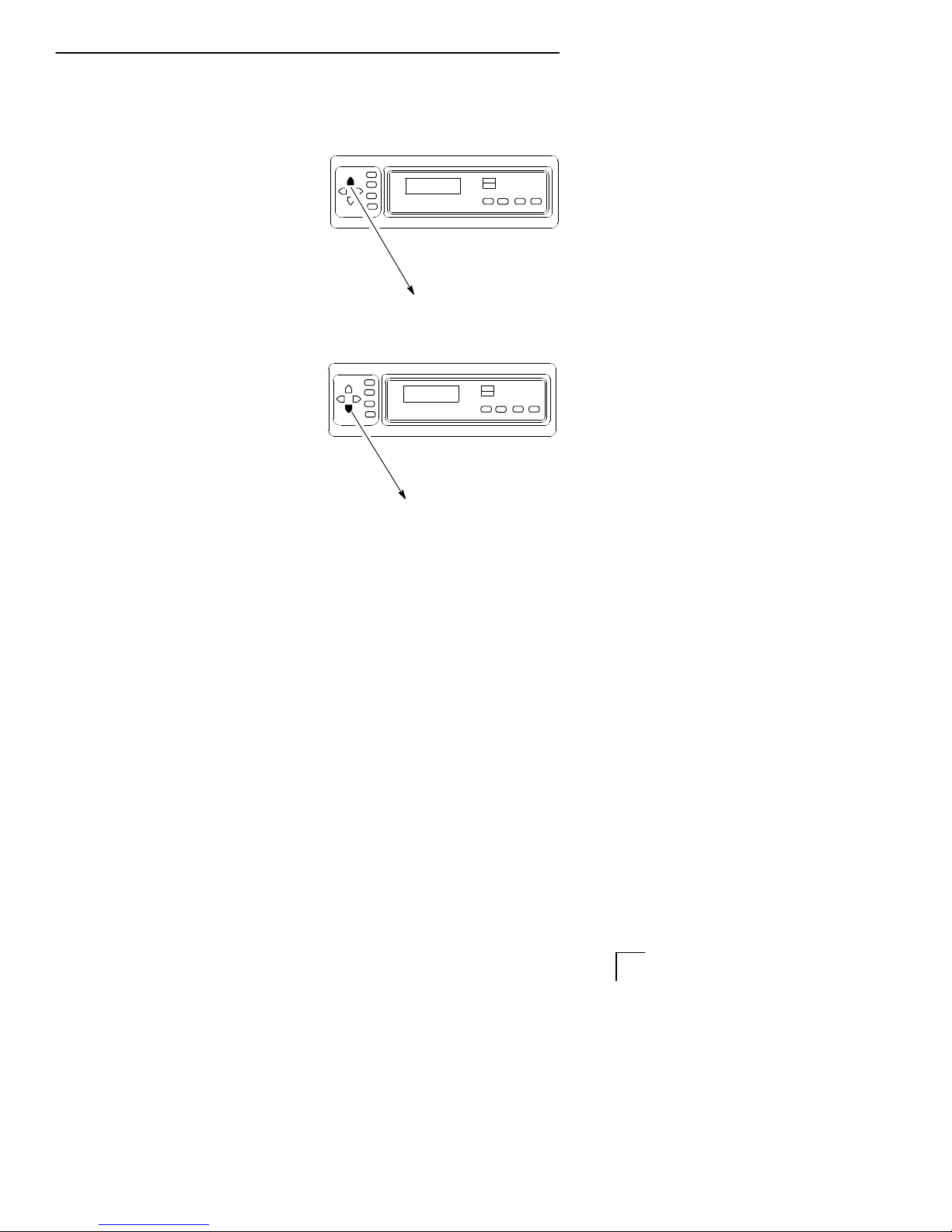
ON LINE
Function Toggles the printer between
online and offline modes.
Action To place the printer in
online mode, press once.
The status indicator
remains continuously lit.
To place the printer in
offline mode, press once.
The status indicator is off.
Result When the printer is in online
mode, it is ready to receive
data and control commands
from the host computer,
and prints the data
immediately.
When the printer is in offline
mode, printing stops after
the current line finishes
printing. Communication
with the host stops, and you
may perform operator
functions such as setting the
top–of–form or configuring
the printer.
ON LINE
8 Operator’s Guide
Page 17

FF (Form Feed)
Function Causes the paper to
advance to the top–of–form
on the next page.
Action In online or offline mode,
press and release to
advance the paper to the
top–of–form on the next
page. If there is data in the
printer’s buffers, the data
will print and then the paper
will move to the next
top–of–form.
Other In the fault state FF does
not advance the paper to
the next top–of–form;
instead, it will slew the
paper 1 1 inches.
using the control panel
FF
9Operator’s Guide
Page 18

using the control panel
LF (Line Feed)
Function Advances the paper one
line at a time. Unprinted
data in the print buffer will
print before the paper
moves.
Action With the printer offline,
press and release to
advance the paper one line
at a time.
If there is data in the printer
buffer, the data will print
before the line feed occurs.
Press and hold to repeat
forward paper movement.
Other LF does not operate in the
fault or online states.
LF
10 Operator’s Guide
Page 19
VIEW (Forms Alignment)
Function In offline or online mode,
allows you to view and adjust
the placement of data on the
page, or to remove peel-off
labels.
using the control panel
Action In offline mode, press and
release to move the last data
printed to the tractor area for
viewing. Press VIEW a
second time to move the last
data printed back to the print
position.
To adjust fine vertical forms
alignment while the printer is
online and printing, press VIEW
to stop printing and move the
last data printed to the viewing
area; press Y or B to adjust
the paper up or down in 1/75”
increments; press VIEW a
second time to move the paper
back to its original print position
and return the printer to online.
Pressing ON LINE also moves the paper
back to its original print position and returns
the printer to online.
VIEW
11Operator’s Guide
Page 20

using the control panel
CLEAR
Function Clears a fault message and
returns the printer from fault
mode to offline mode.
Action After correcting a fault
condition, press and release.
Result The fault message is
cleared, and the printer
returns to offline mode.
Other 1) Press CLEAR+ENTER to
cancel a print job. The print job
must also be stopped from the
host system (see page 36).
2) Press CLEAR to move from
anywhere in the configuration
menus to the top menu
(“OFFLINE/CONFIG. CONTROL”)
CLEAR
12 Operator’s Guide
Page 21

R/S (Run/Stop)
Function Starts and stops diagnostic
tests, and generates a
configuration printout.
Action In the configuration
menus, when one of the
DIAGNOSTICS menu
Printer Tests displays
(such as Shift Recycle),
press R/S to start the test.
Press R/S again to stop
the test.
using the control panel
R/S
13Operator’s Guide
Page 22

using the control panel
SET TOF (Top–of–Form)
Function Sets the top–of–form on the
printer. This key is active
only when the printer is
offline and will not operate if
the printer is in a fault
condition.
Action Raise the forms thickness
lever; align the first print
line (directly below the
perforation) with the TOF
indicator on the tractor;
close the forms thickness
lever; then press SET TOF.
(See page 23 for a
complete procedure.)
Result The paper moves down to
the print position and aligns
to the top–of–form.
Other This key is not active during
a fault condition.
SET TOF
14 Operator’s Guide
Page 23

ENTER
Function In the menus, selects the
currently displayed option
value as the active value.
Action When the display shows the
desired configuration value,
press and release to select
that value as the active
value. An asterisk (*)
appears next to the active
value on the display .
(The ENTER key must be
unlocked before you can use
it to select option values. To
unlock the ENTER key,
press Y+B at the same
time from offline mode. To
relock the ENTER key, press
Y+B a second time.)
using the control panel
ENTER
Other Starts and stops printer tests,
and generates a configuration
printout. Press ENTER to start
a printer test (or configuration
printout). Press again to stop
the printer test.
15Operator’s Guide
Page 24
using the control panel
UP and DOWN ( Y and B )
Function Moves up and down between
levels in the configuration
menus.
In offline mode, press both
keys at the same time to
toggle the ENTER key
between locked and unlocked.
Action In the configuration menus,
press Y to move to a higher
level in the menu structure.
Press B to move to a lower
level in the menu structure.
In offline mode, press Y+B
at the same time to unlock
the ENTER key; press them
again to relock the ENTER
key.
Other After pressing VIEW, press Y
or B to adjust the paper up
or down in 1/75” increments
for fine vertical forms
alignment (see page 1 1).
UP
Y
B
DOWN
16 Operator’s Guide
Page 25

PREV and NEXT ( A and " )
Function Moves between the options
on the current level of the
configuration menu.
When both keys are
pressed simultaneously , the
printer will reset to the
power–up configuration and
reset its internal state.
Action In the configuration menu,
press A
or press " to scroll forward
through menu selections on
the same level.
to scroll backward
PREV
using the control panel
A
Press A +
printer by reloading the
power–up configuration and
resetting the printer’s
internal state.
" to reset the
"
NEXT
17Operator’s Guide
Page 26

18 Operator’s Guide
Page 27

Loading Paper
This procedure shows you how to load
paper into an empty printer or change the
paper supply to a different size.
To reload the paper after a “LOAD PAPER”
fault message, refer to page 26.
Press ON LINE to place the
printer in offline mode.
Open the printer cover.
Unload the current paper, if
necessary (page 30).
Tractor Door
Raise the forms thickness lever
as far as it will go.
Open both tractor doors.
Forms
Thickness
Lever
19Operator’s Guide
Page 28

loading paper
Open the cabinet front door.
Align the paper supply with
the label on the floor.
Ensure that the paper pulls
freely from the box.
Feed the paper up through the
paper slot inside the cabinet.
Hold the paper to prevent it
from slipping down through the
paper slot.
EDGE
OF
PAPER
BOX
Paper Slot
20 Operator’s Guide
Page 29

loading paper
Pull the paper above and behind
the ribbon mask. (The ribbon
mask location is shown on the
ribbon path diagram.)
Load the paper on the left
tractor and close the tractor
door.
Normally, you should not need
to adjust the position of the left
tractor.
If adjustment is necessary,
unlock the left tractor. Slide the
tractor until it is aligned directly
to the left of the number “1” on
the paper scale and lock it.
(You can also use the paper
scale to count columns.)
Tractor Door
Paper
Ribbon Path
Diagram
To avoid damage to the printer caused
by printing on the platen, always
position the left tractor unit directly to
the left of the “1” mark on the paper
scale.
Paper Scale
21Operator’s Guide
Page 30

loading paper
Unlock the right tractor.
Load the paper onto the
sprockets and close the
tractor door.
If necessary, slide the right
tractor to remove paper
slack or to adjust for
various paper widths. Then,
lock the tractor.
After both tractors are
secured, you may use the
horizontal adjustment knob
to make fine horizontal
paper adjustments.
Tractor Door
Tractor Lock
Close the cabinet front door.
Continue on to the next
section to set the
top–of–form.
22 Operator’s Guide
Horizontal
Adjustment Knob
Page 31

Setting Top-of-Form
The top-of-form setting determines where
the first line of print appears on a page.
Be sure to set the top–of–form under the
following conditions:
• Before each new print job
• After loading paper
• After clearing a paper jam
Follow this procedure to set the
top-of-form.
Make sure the printer is in offline
mode. (Press ON LINE to toggle
from online to offline mode.)
Press FF several times to make sure
the paper feeds properly beyond the
tractors and over the lower paper
guide. Feed sufficient paper to
ensure the paper stacks correctly.
Paper
Guide
Open the printer cover. Raise the
forms thickness lever as far as it
will go. ( If the cover and lever
are already raised, go directly to
Step 4.)
Forms
Thickness
Lever
23Operator’s Guide
Page 32

Align the top of the first print
line with the TOF indicator on
the tractor by rotating the
vertical position knob.
The first print line on the form
should be 1/2 inch or more from
the perforation for best print
quality.
Lower the forms thickness
lever. Set it to match the paper
thickness.
(The A–B–C scale corresponds
approximately to 1–, 3–, and
6–part paper thickness. Adjust
until you have the desired print
quality.)
TOF Indicator
Thin Paper
Medium Paper
Thick Paper
Perforation
Vertical
Position
Knob
Do not set the forms thickness lever too
tightly; excessive friction can cause paper
jams, ribbon jams with potential for ribbon
damage, smeared ink, or wavy print.
24 Operator’s Guide
Page 33

Press CLEAR to clear any fault
messages (such as “LOAD
P APER”) from the Liquid Crystal
Display.
Press SET TOF. The top–of–form
you have set moves down to the
print position. (If there is data in the
buffer, the paper moves back to the
last print position.)
Press ON LINE and close the
printer cover.
25Operator’s Guide
Page 34

Reloading Paper
Follow this procedure when “LOAD
PAPER” displays. (This message
occurs when the last sheet of paper
passes through the paper slot.) Use
this procedure to reload paper without
removing the last sheet of the old paper
supply.
If you are using multi-part paper and it is
too thick for the new paper to be loaded
over the existing paper, do not use this
procedure. Instead, remove the existing
paper and load new paper using the
loading paper procedure (page 19).
Raise the printer cover. Raise
the forms thickness lever as far
as it will go.
Do not open the tractor doors or
remove the existing paper.
Forms
Thickness
Lever
26 Operator’s Guide
Page 35

Open the cabinet front door.
Align the paper supply with the
label on the floor.
Ensure that the paper pulls
freely from the box.
Locate the paper slot inside
the cabinet and feed the
paper up through the slot.
It may be easier to feed one corner of the
new paper up through the slot first. When
this corner can be grasped from the top,
rotate the paper back to the normal
position. If necessary, gently press the
existing paper back.
reloading paper
EDGE
OF
PAPER
BOX
Hold the paper to prevent it
from slipping down and through
the paper slot.
Paper Slot
27Operator’s Guide
Page 36

reloading paper
Pull the new paper above and
behind the ribbon mask, but in
front of the existing paper. (The
ribbon mask location is shown on
the ribbon path diagram.)
If necessary, gently press the
existing paper back.
Align the top edge of the new
paper with the top perforation
of the existing paper.
New Paper
Existing
Paper
Load the new paper over the
existing paper.
Open and load the tractors one
at a time to prevent the paper
from slipping.
Ensure that the top edge of the new paper
lines up with the top perforation of the
existing paper.
Ribbon Path
Diagram
28 Operator’s Guide
Page 37

6 Lower the forms thickness lever. Set
it to match the paper thickness.
(The A–B–C scale corresponds
approximately to 1–, 3–, and 6–part
paper thickness. Adjust until you
have the desired print quality .)
caution
Do not set the forms thickness lever too
tightly; excessive friction can cause
paper jams, ribbon jams with potential
for ribbon damage, smeared ink, or
wavy print.
7 Press CLEAR to clear the
“LOAD PAPER” fault message
from the Liquid Crystal Display .
A
Thin Paper
B
Medium Paper
C
Thick Paper
reloading paper
8 Close the printer cover.
Close the cabinet front door.
9 Press ON LINE to place the
printer in online mode and
resume printing.
10 Open the cabinet back door
and ensure that the paper folds
in the stacker the same way it
does in the supply area, then
close the cabinet back door.
29Operator’s Guide
Page 38

Unloading Paper
To unload paper from the printer,
perform the following steps.
Press ON LINE to place the
printer in offline mode, and
open the printer cover.
Tear off the paper at the
perforation.
Allow the paper to fall to the
back of the printer and into
the paper stacking area.
Raise the forms thickness
lever as far as it will go.
Open both tractor doors.
Perforation
Tractor Door
Forms
Thickness
Lever
30 Operator’s Guide
Page 39

unloading paper
4 Remove the paper from the
tractors. Open the cabinet front
door.
Gently
pull the paper down
through the paper slot.
Do not let the paper
perforations or tractor holes
damage the ribbon mask. (The
ribbon mask location is shown
on the ribbon path diagram.)
Allow the paper to fall into the
paper supply area.
caution
Be careful when pulling any paper
backwards through the paper path,
especially when using label stock. If you
are not careful, labels can detach and
adhere to the printer within the paper
path, where only a Digital service
representative can remove them.
Tractor
Ribbon Path Diagram
Cabinet
Front
Door
5 Remove the stacked paper from
the cabinet floor.
6 Close the cabinet front door.
7 Close the printer cover.
31Operator’s Guide
Page 40

Replacing the Ribbon
When replacing ribbons, use only the
ribbons listed below:
Use of ribbons that do not meetDigital
specifications may void warranty.
Part Number Description
LGxxR–SR One OCR Application 60–yard ribbon (LG04 ribbon)
Length: 60 yards (54.84 m)
Width: 1 inch (2.54 cm)
Thickness: .0039 inches (.009906 cm)
LGxxR–LR One OCR Application 100–yard ribbon (LG04 ribbon)
Length: 100 yards (91.4 m)
Width: 1 inch (2.54 cm)
Thickness: .0039 inches (.009906 cm)
To order replacement ribbons, call
1–800–DIGITAL.
32 Operator’s Guide
Page 41

Press ON LINE to place the
printer in offline mode, and open
the printer cover.
Remove the old ribbon:
Raise the forms thickness
lever as far as it will go.
Press in on the hub latches
and lift the ribbon spools off
the hubs. Lift the ribbon out
of the ribbon path. (Refer to
the ribbon path diagram on
the shuttle cover.)
Discard the old ribbon.
If necessary, clean the interior
of the printer. (See page 59.)
replacing the ribbon
Hub Latch
Forms
Thickness
Lever
33Operator’s Guide
Page 42

replacing the ribbon
Install the new ribbon:
With the ribbon to the outside,
place the right spool on the
right hub. Press down on the
spool until the hub latch snaps
in place.
Thread the ribbon around
the ribbon guide and along
the ribbon path. (Refer to
the ribbon path diagram on
the shuttle cover.) Be sure
to thread the ribbon
between the hammer bank
cover and the ribbon mask.
The ribbon must not be twisted. A twisted
ribbon can lower print quality, shorten
ribbon life, or cause paper jams.
Hub
Latch
Hammer
Bank
Cover
Ribbon
Mask
Ribbon
Guide
Place the left spool on the left hub.
Press down on the spool until the
hub latch snaps into place.
Hand–turn the right spool to make
sure the ribbon tracks correctly in
the path and ribbon guides.
34 Operator’s Guide
Page 43

5 Lower the forms thickness
lever. Set it to match the paper
thickness you are using.
A
Thin Paper
replacing the ribbon
(The A–B–C scale
corresponds approximately to
1–, 3–, and 6–part paper
thickness. Adjust until you
have the desired print
quality.)
caution
Do not set the forms thickness lever too
tightly; excessive friction can cause paper
jams, ribbon jams with potential for ribbon
damage, smeared ink, or wavy print.
6 Close the printer cover.
7 Press ON LINE to return the
printer to online mode.
B
Medium Paper
C
Thick Paper
35Operator’s Guide
Page 44

Canceling a Print Job
The procedure to cancel a print job depends
on the printer emulation and your application
software. See your System Administrator for
additional information.
Place the printer offline.
From the host system, stop the
print job.
If the print job is not stopped from the host
system before pressing CLEAR + ENTER,
the print job will continue with data missing
when the printer returns to online.
Exercise caution to prevent unwanted data
loss occurrences as this function will delete
unprinted data in the printer. This function
is active only in an offline condition; the
purpose of this function is to eliminate the
necessity of printing unwanted data when
print jobs are canceled.
Press CLEAR + ENTER.
Set the top–of–form, as
described on page 23.
36 Operator’s Guide
Page 45

CONFIGURATION
♦ Configurations and Parameters 38
♦ Saving Configurations 44
♦ Printing Configurations 46
♦ Loading Configurations 48
♦ Deleting Configurations 50
♦ The Power–Up Configuration 52
37Operator’s Guide
Page 46

Configurations and Parameters
The following pages describe how to save,
print, load and delete entire configurations,
as well as how to select a power–on
configuration.
Configurations
A configuration is a group of parameter
settings. For example:
• 8 lpi
• 10 cpi
• Data processing typeface, etc.
Nine configurations are available. Your
printer has a preset factory configuration that
cannot be changed or deleted, configuration
0. Configurations 1 to 8 are provided so that
you can store custom configurations to meet
specific print job requirements.
To create a custom configuration, modify any
printer parameters as needed from the
default values, then save the modified
configuration (as number 1 to 8) using the
“Save Config.” menu option.
38 Operator’s Guide
Page 47

Once you have defined and saved a
configuration to nonvolatile memory , it will
not be lost if you power off the printer . You
can load or delete configurations; you can
also modify and overwrite (resave) them.
Configurations 1 to 8 are undefined until
you define them using the “Save Config.”
menu option.
configurations and parameters
39Operator’s Guide
Page 48

configurations and parameters
Parameters
Printer parameters are settings such as line
spacing (lpi), characters per inch (cpi), typeface,
etc. You can change a parameter by pressing
keys on the operator panel or by sending a
control code from the host computer.
A parameter such as 8 lpi is effective as long
as the printer is on. To save the 8 lpi
parameter, you must use the operator panel
and save it as part of a configuration.
To learn more about the configuration menus
and how to change individual parameters
such as line spacing, typeface, etc., refer to
plus
the
LG
Series Setup Guide
or the
programming reference manual for each
emulation.
Control Codes
Control codes override parameters that were
changed with the operator panel. For example, if
you set line spacing to 6 lpi with the operator
panel, and application software later changed
this to 8 lpi with a control code, then 8 lpi would
be the new, active parameter.
40 Operator’s Guide
Page 49

configurations and parameters
The Configuration Menus
The following two pages show a summary of the
entire set of configuration menus available with
plus
the LG
procedures for configuring particular menu
options from the Config. Control Menu.
Series
. Following this are several
Refer to the
descriptions of the configuration menu options.
plus
LG
Series Setup Guide
for
41Operator’s Guide
Page 50

configurations and parameters
OFFLINE
CONFIG.
CONTROL
Load Config.
0* – 8
Save Config.
1* – 8
Print Config.
Current*
Factory
Power–up
All
1 – 8
Delete Config.
1* – 8
Power–up Config.
0* – 8
Protect Configs.
Disable*
Enable
HOST
INTERFACE
(continued)
Dataproducts
Data Bit 8
Enable*/ Disable
PI Ignored
Enable*/ Disable
Data Polarity
Standard*/ Inverted
Data Request Pol.
Standard*/ Inverted
Strobe Polarity
Standard*/ Inverted
Buffer Size in K
8* (1–16)
Bidirectional
Buffer Size in K
8* (1–16)
ACTIVE
EMULATION
LG *
LinePrinter+
IGP/PGL & LP+
IGP/VGL & LP+
if installed
(see PGL or VGL
User’s Manual)
CONTROL
Unidirectional
Disable*
Enable
PMD Fault
Enable*
Disable
Slow Paper Slew
Disable*
Enable
Power Saver Time
15 min.*
(15–60)
PRINTER
EMULATION
LG *
Font
Font Style
DP 10 6*
(34 options)
Font Char. Set
U.S. ASCII*
(23 options)
Vert. Forms
Bot. Frm 66/6*
Top Mrg. 0/6*
(range 0–198 lines)
Horiz. Forms
Left Mrg. 0.0*
Right Mrg. 13.2*
(range 0–13.2 inches)
Autowrap
No*
Yes
CR
CR=CR * / CR=CR+LF
LF
LF=LF * / LF=CR+LF
Unsolicited Rpt.
No* / Small / Big
Print Mode Opt
Enable* / Disable
Plot Mode Opt
Enable* / Disable
LinePrinter+
SEE NEXT PAGE
Printer Tests
Test Width
Paper Out Dots
System Memory –
Print Statistics
1
MAINT / MISC
Hex Dump Mode
Disable*
Enable
Power–up State
Online*
Offline
Display Language
English*
German
French
Spanish
Italian
DIAGNOSTICS
Shift Recycle*, All E’s,
E’s + TOF, All H’s,
All Underlines, All Black,
Shuttle Slow, Shuttle Fast,
Shuttle Only, Phase Printer,
Paperout Adj., Burnin Test
Full Width*
80 col.
48 dots*
(Range 4–76)
X Megabytes
On X.X Hrs
Print: X.X Hrs
Print Strokes
Print Lines
11 inch Pages
HOST
INTERFACE
Serial*
Interface Type
RS 232* / RS 422
Data Protocol
XON/XOFF*, ETX/ACK,
ACK/NAK, DTR
Baud Rate
1200, 2400, 4800,
9600*, 19200, 38400,
57600, 115200 Baud
Word Length
8* or 7
Stop Bits
1* or 2
Parity
None*, Odd, Even,
Mark, Sense
Data Terminal Ready
True*
False
On-line and BNF
Off-line or BF
Request to Send
True*
False
On-line and BNF
Off-line or BF
Buffer Size in K
8* (1–16)
Parallel
Centronics
Data Bit 8
Enable*/ Disable
Data Polarity
Standard*/ Inverted
Strobe Polarity
Standard*/ Inverted
Resp. Polarity
Standard*/ Inverted
Busy On Strobe
Enable*/ Disable
Latch Data On
Leading*/Trailing
Prime Signal
Enable*/Disable
TOF Action
Reset*/Do Nothing
Buffer Size in K
8* (1–16)
(continued to left)
1
Only the current Active Emulation will display on the Emulation menu.
The default is LG.
42 Operator’s Guide
Page 51

configurations and parameters
LinePrinter+
Printer
Protocol
Define CR Code
CR=CR*
CR=CR+LF
Auto LF
Enable*
Disable
Define LF Code
LF=LF*
LF=CR+LF
FF Valid at TOF
Disable
Enable*
Character Set
Code Page 437*
Set 1*
Set 2
Code Page 850
Set 1*
Set 2
OCR–A
OCR–B
20 CPI Condensed
Enable*
Disable
CPI/LPI
Select
Select CPI
10.0 CPI*
12.0 CPI
15.0 CPI
17.1 CPI
20.0 CPI
Select LPI
6.0 LPI*
8.0 LPI
10.3 LPI
Epson FXProprinter XL*
Define CR Code
CR=CR*
CR=CR+LF
Auto LF
Enable*
Disable
Define LF Code
LF=LF*
LF=CR+LF
Printer Select
Disable*
Enable
Character Set
Epson Set*
ASCII (USA)*
(14 options)
OCR–A
OCR–B
IBM PC
20 CPI Condensed
Enable*
Disable
P–Series
Control Code 06
8.0 LPI*
10.3 LPI
6.0 LPI
Control Code 08
Elongated*
Backspace
Define CR Code
CR=CR*
CR=CR+LF
Auto LF
Disable*
Enable
Overstrike
Enable*
Disable
Define LF Code
LF=CR+LF*
LF=LF
Select SFCC
1B*
(Range 00–7F hex)
EVFU Select
Enable*
Disable
Alt. Set 80–9F
Control Code*
Printable
Character Set
IBM PC*
Primary/Extended
Multinational
ECMA Latin 1
Primary/Extended
DEC Mult.
OCR–A
OCR–B
Font
Attributes
Typeface
Data Processing*
NLQ
OCR A
OCR B
High Speed
NLQ Sans Serif
Prop. Spacing
Disable*/Enable
Bold Print
Disable*/Enable
Italic Print
Disable*
Forward Slant
Backward Slant
Slashed Zero
Disable*/Enable
To view options, press:
To select option value, press ENTER.
To return to main menu, press CLEAR.
To go to online mode, press ON LINE.
* = Factory Default
Margins
Perforation Skip
Form Length
Form Width
Page
Format
Left Margin
0 columns*
(range 0–369)
Right Margin
0 columns*
(range 0–369)
Bottom Margin
0 lines*
(range 0–451)
Disable*
1/2 inch
2/3 inch
5/6 inch
1 inch
Abs. Length IN
11 inches*
(range 1–24)
Abs.Length MM
279.4 mm*
(range .1–609.6)
Funct. of lines
66 lines*
(range 1–192)
Abs. Width IN
13.6 inches*
(range 1–13.6)
Function of CPI
136 Characters*
(range 1–264)
Abs. Width MM
345.4 mm*
(range 1–345.4)
Menu Function
B
Y
"
A
DOWN
UP
NEXT
PREV
43Operator’s Guide
Page 52

Saving Configurations
You can save up to eight unique
configurations. They are stored in
memory and will not be lost if you turn
off the printer .
Configuration 0 is the factory–preset
configuration and cannot be modified
or deleted.
Press ON LINE to place the
printer offline, and raise the
printer cover.
Press Y and B simultaneously
to unlock the control panel. The
message “UNLOCKED” displays
briefly.
Press B.
Press " repeatedly until you
reach the Save Config.
parameter.
Press B.
OFFLINE
CONFIG. CONTROL
ENTER SWITCH
UNLOCKED
CONFIG. CONTROL
Load Config.
CONFIG. CONTROL
Save Config.
Save Config.
1*
44 Operator’s Guide
Page 53

saving configurations
Press " or A until the desired
configuration number (1–8) displays.
Press ENTER to select the value.
An asterisk (*) appears next to the
value in the display . Your active
configuration is now saved as
configuration 2.
Press Y and B simultaneously to
lock the control panel. The
message “LOCKED” displays
briefly.
Press ON LINE. Close the printer
cover. The printer is ready to
resume printing.
Save Config.
2
Save Config.
2*
ENTER SWITCH
LOCKED
ONLINE
45Operator’s Guide
Page 54

Printing Configurations
The configuration printout lists the
stored configuration parameters (line
spacing, forms length, etc.). You can
print the following configurations:
current, factory, power–up, the
customized configurations (1–8), or all of
the configurations.
Press ON LINE to place the
printer offline, and raise the
printer cover.
Press Y and B simultaneously
to unlock the control panel. The
message “UNLOCKED” displays
briefly.
Press B.
Press " repeatedly until you
reach the Print Config.
parameter.
Press B.
OFFLINE
CONFIG. CONTROL
ENTER SWITCH
UNLOCKED
OFFLINE
Load Config.
CONFIG. CONTROL
Print Config.
Print Config.
Current*
Press " or A until the desired
option displays.
46 Operator’s Guide
Print Config.
Factory
Page 55

printing configurations
Press ENTER. The configuration
prints. Tear off the configuration
printout.
If a you try to print a configuration that does
not yet exist (i.e., you have not previously
saved values to that numbered
configuration), then the following fault
message will display:
“CONFIG. DOES NOT EXIST / Save First”
Press Y and B simultaneously to
lock the control panel. The message
“LOCKED” displays briefly.
Press ON LINE.Close the printer
cover. Save the printout in a safe
place. The printer is ready to resume
printing.
OFFLINE
CONFIG. CONTROL
ENTER SWITCH
LOCKED
ONLINE
47Operator’s Guide
Page 56

Loading Configurations
While the printer is on, you can load any
of the eight customized configurations or
the factory default configuration.
The configuration you load will remain in
effect as long as the printer is on. When
you turn the power off and then back on,
the designated power–up configuration
loads. See page 52.
Press ON LINE to place the
printer in offline mode, and open
the printer cover.
OFFLINE
CONFIG. CONTROL
Press Y and B simultaneously to
unlock the control panel. The
message “UNLOCKED” displays
briefly.
Press B.
Press B.
Press " or A until the
configuration you want to load
displays.
ENTER SWITCH
UNLOCKED
OFFLINE
Load Config.
LOAD CONFIG.
0*
LOAD CONFIG
2
48 Operator’s Guide
Page 57

loading configurations
Press ENTER.
If a you try to load a configuration that does
not yet exist (i.e., you have not previously
saved values to that numbered
configuration), then the following fault
message will display:
“CONFIG. DOES NOT EXIST / Save First”
Press Y and B simultaneously to
lock the control panel. The message
“LOCKED” displays briefly.
Press ON LINE and close the printer
cover. The printer is ready to resume
printing.
Loading Saved
Configuration
Load Config.
2*
ENTER SWITCH
LOCKED
ONLINE
49Operator’s Guide
Page 58

Deleting Configurations
You can delete any of your customized
configurations. The factory preset
configuration 0 cannot be deleted.
Press ON LINE to place the
printer offline, and open the
printer cover.
Press Y and B simultaneously to
unlock the control panel. The
message “UNLOCKED” displays
briefly.
OFFLINE
CONFIG. CONTROL
ENTER SWITCH
UNLOCKED
Press B.
Press " repeatedly until you
reach the Delete Config.
parameter.
Press B.
Press " or A until the
configuration you want to delete
displays.
CONFIG. CONTROL
Load Config.
CONFIG. CONTROL
Delete Config.
Delete Config.
1*
Delete Config.
3
50 Operator’s Guide
Page 59

deleting configurations
Press ENTER.
If a you try to delete a configuration that
does not yet exist (i.e., you have not
previously saved values to that numbered
configuration), then the following fault
message will display:
“CONFIG. DOES NOT EXIST / Save First”
Press Y and B simultaneously to
lock the control panel. The
message “LOCKED” displays
briefly.
Press ON LINE and close the
printer cover. The printer is ready
to resume printing.
Deleting
Configuration
Delete Config.
3*
ENTER SWITCH
LOCKED
ONLINE
51Operator’s Guide
Page 60

The PowerĆUp Configuration
When you power on the printer for the first
time, it loads configuration 0, the factory
default configuration.
If you save a configuration, such as
configuration 1, and turn the power off
and then back on, the printer will load
the designated power–up configuration,
not the last saved configuration.
For your convenience, you can specify
which configuration (0–8) should be the
power–up configuration.
Press ON LINE to place the printer
offline, and open the printer cover .
Press Y and B simultaneously to
unlock the control panel. The
message “UNLOCKED” displays
briefly.
Press B.
Press " repeatedly until you reach
the Power–up Config. parameter.
OFFLINE
CONFIG. CONTROL
ENTER SWITCH
UNLOCKED
CONFIG. CONTROL
Load Config.
CONFIG. CONTROL
Power–up Config.
52 Operator’s Guide
Page 61

the powerĆup configuration
Press B.
Press " or A until the
configuration you want displays.
Press ENTER.
If a you try to select a configuration that
does not yet exist (i.e., you have not
previously saved values to that numbered
configuration), then the following fault
message will display:
“CONFIG. DOES NOT EXIST / Save First”
Press Y and B simultaneously
to lock the control panel. The
message “LOCKED” displays
briefly.
Power–up Config.
0*
Power–up Config.
4
Loading Saved
Configuration
Power–up Config.
4*
ENTER SWITCH
LOCKED
Press ON LINE and close the
printer cover. The printer is ready
to resume printing.
ONLINE
53Operator’s Guide
Page 62

54 Operator’s Guide
Page 63

TROUBLESHOOTING
♦ Clearing Paper Jams 56
♦ Cleaning the Printer 59
♦ Solving Print Quality Problems 62
♦ Fault Messages 64
55Operator’s Guide
Page 64

Clearing Paper Jams
Perform the following steps to clear a
paper jam.
caution
Be careful when pulling any paper
backwards through the paper path,
especially when using label stock. If you
are not careful, labels may detach and
adhere to the printer within the paper
path, where only a Digital service
representative can remove them.
1 Open the printer cover.
2 Raise the forms thickness lever
as far as it will go.
3 Open both tractor doors.
4 Check the paper path and
tractors for jammed or torn
paper. Remove any pieces of
paper by turning the vertical
position knob.
Tractor Door
Forms
Thickness
Lever
Vertical
Position
Knob
56 Operator’s Guide
Page 65

Check that the ribbon mask has
not been deformed in such a way
as to block the paper path. (If the
ribbon mask is damaged or bent,
contact an authorized service
representative.)
Check the narrow paper path
between the face of the platen
and the ribbon mask for pieces of
torn paper and ribbon lint. Refer
to the ribbon path diagram on the
shuttle cover.
Reload the paper on the tractors.
If you need to load a new box of
paper, go to page 19. If you need
to set the top-of-form after
reloading paper, go to page 23 and
start at Step 2.
clearing paper jams
Tractor
Ribbon Path Diagram
57Operator’s Guide
Page 66

clearing paper jams
Lower the forms thickness lever.
Set it to match the paper
thickness.
The A–B–C scale corresponds
approximately to 1–, 3–, and
6–part paper thickness. Adjust
until you have the desired print
quality.
Do not set the forms thickness lever too
tightly; excessive friction can cause paper
jams, ribbon jams with potential for ribbon
damage, smeared ink, or wavy print.
Close the printer cover.
Press ON LINE to resume printing.
Thin Paper
Medium Paper
Thick Paper
58 Operator’s Guide
Page 67

Cleaning the Printer
Periodic cleaning ensures efficient
operation and clear print quality .
Disconnect the power source before
cleaning the printer.
Cleaning Exterior of Cabinet
Clean the outside of the cabinet with a
soft, lint-free cloth and mild detergent.
(Dishwashing liquid works well.) Do not
use abrasive powders or chemical
solvents. Clean the windows with plain
water or mild window cleaner.
Always apply the cleaning solution to
the cloth; never pour cleaning solution
directly onto the printer.
Cleaning Inside the Cabinet
Over time, it is normal for particles of
paper and ink to accumulate inside the
printer. Paper dust and ink build-up must
be removed periodically to avoid
degraded print quality . To clean the
interior of the printer, perform the
following steps.
59Operator’s Guide
Page 68

cleaning the printer
caution
To avoid damage to the printer, be
extremely careful when vacuuming and
dusting around the hammer bank and
surrounding areas.
1 Power off the printer and
unplug the power cord.
2 Unload the paper supply
(page 30).
3 Remove the ribbon
(step 2, page 33).
4 Using a soft-bristled,
non-metallic brush, remove
dust particles from the paper
path, ribbon guides, and
ribbon path. (Refer to the
ribbon path diagram on the
shuttle cover.)
Hammer Bank
(hidden)
Ribbon
Path
Diagram
Base
Pan
Splined
Shaft
Ribbon
Guide
5 Brush and vacuum
accumulated dust or residue,
especially in the tractor and
base pan areas, and around
the exterior of the hammer
bank.
60 Operator’s Guide
Page 69

Wipe the splined shaft with a soft
cloth.
Using a cloth dampened with
anhydrous (not diluted with water)
alcohol, clean the ribbon guides.
Do not let alcohol drip into the
hammer bank.
Brush and vacuum inside the
lower cabinet.
Wipe the lower cabinet interior
with a clean, lint-free cloth damp
(not wet) with water and mild
detergent.
Dry the interior with a dry , clean,
lint-free cloth.
cleaning the printer
Interior of
Lower
Cabinet
Load the paper (page 19) and
reinstall the ribbon (page 34).
61Operator’s Guide
Page 70

Solving Print Quality Problems
If you are having print quality problems, locate
your printer problem in the table below and do
the Corrective Action. If more than one
corrective action task is listed, test the printer
after each task. If the problem persists, contact
your authorized service representative.
Problem
Poor print quality:
dark print
light print
light print on half the page
missing dots or characters
smeared print
wavy vertical lines
Torn or damaged forms 1 Reset the forms thickness lever for
1 Adjust the forms thickness lever setting.
(Print quality can be affected if it is too
loose or too tight.)
2 Adjust the paper tension horizontally by
moving the right tractor (print quality can
be affected if the paper is too loose or
too tight).
3 Make sure the ribbon threads around the
ribbon guides and between the hammer
bank cover and ribbon mask, as shown
on the ribbon path diagram. Turn the
ribbon spools to ensure that the ribbon
tracks correctly in the ribbon path.
4 Clean the printer (see page 59).
5 Replace the ribbon (page 32) with an
approved ribbon.
thicker paper.
2 Adjust the paper tension horizontally by
moving the right tractor (print quality can
be affected if the paper is too loose or
too tight).
3 Check the paper slot for foreign material.
Corrective Action
continued next page
62 Operator’s Guide
Page 71

solving print quality problems
Problem Corrective Action
Loss of forms position 1 Set the forms thickness lever for
Asterisk does not appear
after you change a
configuration parameter with
the ENTER key.
The configuration printout
does not represent
configuration parameters
selected and changed.
Lost dots (incompletely
formed characters)
Horizontally or vertically
misaligned character
positions
Erratic character height
Vertically deformed print
thicker paper.
1 With the printer off–line, press UP and
DOWN simultaneously so that the
display reads “UNLOCKED”.
the configuration option you want to
change. Press ENTER when the option
is on the message display .
1 Verify that you have saved the current
configuration (see page 44).
1 Lower the forms thickness lever.
2 Clear the paper path of any
obstructions.
3 If problems persist, contact your Digital
Service Representative.
Display
63Operator’s Guide
Page 72

Fault Messages
When a fault condition occurs, the status lamps
flash, the alarm sounds, and a specific message
appears in the display . When this happens,
correct the fault immediately .
You can correct most faults by performing a
simple procedure, such as clearing a paper jam
or reloading paper. The following pages list
common fault messages and explain how to
correct the fault conditions.
For more serious faults, indicated by an asterisk
(*) following the fault message, a Digital
Customer Service Engineer may be needed.
Perform the following steps to clear a fault
message after you have corrected the fault
condition,
Service Engineer for the faults indicated by an
asterisk (*):
and
before you call a Digital Customer
Press CLEAR, then ON LINE to
continue printing.
If the fault message reappears, turn
the printer power off, wait 15 seconds,
then turn the printer back on. Run your
print job again. If the message does
not reappear during printing, no further
attention is required. If the fault
message reappears, go to step 3.
Press CLEAR, then ON LINE again
and resume printing. If the message
does not appear, no further attention is
required. If the message reappears,
call your Digital Customer Service
Engineer.
64 Operator’s Guide
Page 73

fault messages
8.5V PWR FAIL*
15V CTL FAIL*
23.5V CTL FAIL*
48V PWR FAIL*
ACCESS NULL PTR*
A TO D OVERUN*
8.5V PWR FAIL*
Internal power failure. Contact your
Digital Customer Service Engineer.
15V CTL FAIL*
Controller voltage failure. Contact your
Digital Customer Service Engineer.
23.5V CTL FAIL*
Controller voltage failure. Contact your
Digital Customer Service Engineer.
48V PWR FAIL*
Internal power failure. Contact your
Digital Customer Service Engineer.
ACCESS NULL PTR*
Fatal firmware error on CMX controller
board. Contact your Digital Customer
Service Engineer.
A TO D OVERUN*
Fatal firmware error on CMX controller
board. Contact your Digital Customer
Service Engineer.
BAD VFU CHANNEL
BUFFER OVERFLOW
BAD VFU CHANNEL
Error in channel assignment for a Vertical
Format Unit (VFU), for one of the
LinePrinter Plus emulations. Refer to the
LinePrinter Plus Programming Reference
Manual
for further information.
BUFFER OVERFLOW
Host sends data after the printer buffer is
full. (Serial interface.) Check your serial
host interface parameter settings; if
necessary, adjust them so that they
match the settings of the attached host.
65Operator’s Guide
Page 74

fault messages
CLEAR PAPER JAM
CLOSE PLATEN
COIL HOT
CTL VOLT FAIL*
DRVR CIR BAD*
ENERGY STAR
CLEAR PAPER JAM
Clear jam and reload paper (see page 56). If
this message recurs, contact your Digital
Customer Service Engineer.
CLOSE PLATEN
The forms thickness lever is open. Close
the forms thickness lever.
COIL HOT
One or more hammer coils are
overheating. Contact your Digital
Customer Service Engineer.
CTL VOLT FAIL*
Controller voltage failure. Contact your
Digital Customer Service Engineer.
DRVR CIR BAD*
Hammer coil count test failed. Contact
your Digital Customer Service Engineer.
ENERGY STAR
Status message: printer is in low–energy
idle state, all fans and higher voltages
are off, only+5Vdc logic circuits are
active. No action required.
EXHAUST FAN FLT
EXHAUST FAN FLT
Sensors cannot detect current in fan
circuit. Power off the printer and remove
the paper path. Check that the fan cable
connector is connected. Check for
obstruction of vents and fan airway , and
remove any obstructions. Check for items
beneath the printer blocking cabinet vents.
Power back on the printer. If this message
recurs, contact your Digital Customer
Service Engineer.
66 Operator’s Guide
Page 75

fault messages
FIRMWARE ERROR
FRAMING ERROR
HAM. COIL OPEN*
HB NOT INSTALLD*
FIRMWARE ERROR
Application software tried to perform an
illegal printer function or damaged memory
detected on CMX board.Contact your Digital
Customer Service Engineer.
FRAMING ERROR
Serial framing error (serial interface).
Check your serial host interface
parameter settings; if necessary , adjust
them so that they match the settings of
the attached host.
HAM. COIL OPEN*
Electrical malfunction of one or more
hammer coils. Contact your Digital
Customer Service Engineer.
HB NOT INSTALLED*
Self–test does not detect hammer coils.
Contact your Digital Customer Service
Engineer.
HMR BANK FAN FLT
ILL EXT BUS ACC*
HMR BANK FAN FLT
Sensors cannot detect current in fan
circuit. Power off printer and remove
paper path. Check that fan cable is
connected. Check for obstruction of vents
and fan airway; remove any obstructions.
Check for items beneath the printer
blocking cabinet vents. Power back on
the printer. If this message recurs,
contact your Digital Customer Service
Engineer.
ILL EXT BUS ACC*
Fatal firmware error on CMX controller
board. Contact your Digital Customer
Service Engineer.
67Operator’s Guide
Page 76

fault messages
ILL INST ACCSS*
ILLGL OPR ACCSS*
INTAKE FAN FAULT
LO DRV. SHORT*
LOAD PAPER
ILL INST ACCSS*
Fatal firmware error on CMX controller
board. Contact your Digital Customer
Service Engineer.
ILLGL OPR ACCSS*
Fatal firmware error on CMX controller
board. Contact your Digital Customer
Service Engineer.
INTAKE FAN FAULT
Sensors cannot detect current in fan
circuit. See description for HMR BANK
FAN FLT.
LO DRV. SHORT*
Circuit(s) on the hammer bank or in the
hammer bank power cable shorted to
ground. Contact your Digital Customer
Service Engineer.
LOAD PAPER
Printer is out of paper. Load paper.
PAP BAD TABLE*
Fatal firmware error on CMX controller
board. Contact your Digital Customer
Service Engineer.
PAP BAD TABLE*
PAP BSY TOO LNG*
PAP BSY TOO LNG*
Fatal firmware error on CMX controller
board. Contact your Digital Customer
Service Engineer.
PAP FIFO OVERFL*
PAP FIFO OVERFL*
Fatal firmware error on CMX controller
board. Contact your Digital Customer
Service Engineer.
68 Operator’s Guide
Page 77

fault messages
PAP FIFO UNDRFL*
PAP ILLGL ST*
PAP INCMPL ENER*
PAP INVLD CMD*
PAP INVLD PARM*
PAP FIFO UNDRFL*
Fatal firmware error on CMX controller
board. Contact your Digital Customer
Service Engineer.
PAP ILLGL ST*
Fatal firmware error on CMX controller
board. Contact your Digital Customer
Service Engineer.
PAP INCMPL ENER*
Fatal firmware error on CMX controller
board. Contact your Digital Customer
Service Engineer.
PAP INVLD CMD*
Fatal firmware error on CMX controller
board. Contact your Digital Customer
Service Engineer.
PAP INVLD PARM*
Fatal firmware error on CMX controller
board. Contact your Digital Customer
Service Engineer.
PAP NOT SCHED*
PAP NT AT SPEED*
PAP UNEXP INT*
PAP NOT SCHED*
Fatal firmware error on CMX controller
board. Contact your Digital Customer
Service Engineer.
PAP NT AT SPEED*
Fatal firmware error on CMX controller
board. Contact your Digital Customer
Service Engineer.
PAP UNEXP INT*
Fatal firmware error on CMX controller
board. Contact your Digital Customer
Service Engineer.
69Operator’s Guide
Page 78

fault messages
PARITY ERROR
PLAT INV CMD*
PLAT INV PARM*
PLAT INV STATE*
POWER SUPPLY HOT
PARITY ERROR
Parity error (serial interface). Check your
serial host interface parameter settings; if
necessary, adjust them so that they
match the settings of the attached host.
PLAT INV CMD*
Fatal firmware error on CMX controller
board. Contact your Digital Customer
Service Engineer.
PLAT INV PARM*
Fatal firmware error on CMX controller
board. Contact your Digital Customer
Service Engineer.
PLAT INV STATE*
Fatal firmware error on CMX controller
board. Contact your Digital Customer
Service Engineer.
POWER SUPPLY HOT
Circuits are overheating on the power
supply board. Contact your Digital
Customer Service Engineer.
PRINTER HOT
PRINTER HOT
Controller board sensors report high
temperatures on the board. Contact your
Digital Customer Service Engineer.
PROTECTED INSTR*
PROTECTED INSTR*
Fatal firmware error on CMX controller
board. Contact your Digital Customer
Service Engineer.
PWR SUPP VOLT*
PWR SUPP VOLT*
Power supply failed. Replace power
supply board.
70 Operator’s Guide
Page 79

RIB INVLD CMD*
fault messages
RIB INVLD CMD*
Fatal firmware error on CMX controller
board. Contact your Digital Customer
Service Engineer.
RIB INVLD STATE*
RIBBON DRIVE
SECURITY VIOLATION
SHUTL INV CMD*
SHUTL INV PARM*
RIB INVLD STATE*
Fatal firmware error on CMX controller
board. Contact your Digital Customer
Service Engineer.
RIBBON DRIVE
CMX controller does not detect ribbon
drive motor. Contact your Digital
Customer Service Engineer.
SECURITY VIOLATION
Security code of P AL on controller board
does not match code of firmware on the
CMX controller board. Contact your
Digital Customer Service Engineer.
SHUTL INV CMD*
Fatal firmware error on CMX controller
board. Contact your Digital Customer
Service Engineer.
SHUTL INV PARM*
Fatal firmware error on CMX controller
board. Contact your Digital Customer
Service Engineer.
SHUTTLE JAM
SHUTTLE JAM
No shuttle movement or shuttle moving
at wrong speed. Check for obstruction to
shuttle, a twisted ribbon, or forms
thickness lever closed too tightly . If fault
source is not apparent, contact your
Digital Customer Service Engineer.
71Operator’s Guide
Page 80

fault messages
SOFTWARE ERROR*
Cycle power
STACK OVERFLOW*
STACK UNDERFLOW*
TCB CORRUPTED*
SOFTWARE ERROR*
Application software tried to perform
illegal printer function, or damaged logic
circuits found on controller board.
Contact your Digital Customer Service
Engineer.
STACK OVERFLOW*
Fatal firmware error on CMX controller
board. Contact your Digital Customer
Service Engineer.
STACK UNDERFLOW*
Fatal firmware error on CMX controller
board. Contact your Digital Customer
Service Engineer.
TCB CORRUPTED*
Fatal firmware error on CMX controller
board. Contact your Digital Customer
Service Engineer.
UNDEF INTERRUPT*
UNDEF INTERRUPT*
Fatal firmware error on CMX controller
board. Contact your Digital Customer
Service Engineer.
UNDFNED OPCODE*
UNDFNED OPCODE*
Fatal firmware error on CMX controller
board. Contact your Digital Customer
Service Engineer.
UP DRV. SHORT*
UP DRV. SHORT*
Hammer driver circuits on the CMX
boards shorted to ground. Contact your
Digital Customer Service Engineer.
72 Operator’s Guide
 Loading...