

Digital Equipment LG06 Maintenance Manual

LG06
Text and Graphics Printer
Maintenance Manual
latigid
Order Number: EK–ELG06–MG

LG06
Text and Graphics Printer
Maintenance Manual
Order Number: EK–ELG06–MG
Digital Equipment Corporation • Merrimack, NH 03054

2nd Edition, July 1992
Digital Equipment Corporation 1991, 1992
All Rights Reserved
The information in this document is subject to change without notice and should
not be construed as a commitment by Digital Equipment Corporation. Digital
Equipment Corporation assumes no responsibility for any errors that may appear
in this document.
Printed in U.S.A.
The following are trademarks of Digital Equipment Corporation:
DATATRIEVE
DEC
DECmate
DECset
DECsystem
DECUS
DECwriter
DECxpress
The DIGITAL logo
DIBOL
IVAX
MASSBUS
PDP
P/OS
Professional
Rainbow
RSTS
FCC USER STATEMENT
NOTICE:
This equipment generates, uses, and may emit radio frequency. The equipment has
been type tested and found to comply with the limits for a Class A computing device
pursuant to Subpart J of Part 15 of FCC rules, which are designed to provide reasonable
protection against such radio frequency interference. Operation of this equipment in a
residential area may cause interference in which case the user at his own expense will
be required to take whatever measures may be required to correct the interference.
RSX
Scholar
ULTRIX
UNIBUS
VAX
VMS
VT
Work Processor

Table of Contents
1 Maintenance Overview
About This Manual 1–2. . . . . . . . . . . . . . . . . . . . . . . . . . . . . . . . . . . . . . . . .
Related Documents 1–2. . . . . . . . . . . . . . . . . . . . . . . . . . . . . . . . . . . . . .
How to Use This Manual 1–2. . . . . . . . . . . . . . . . . . . . . . . . . . . . . . . . . .
Warnings and Special Information 1–2. . . . . . . . . . . . . . . . . . . . . . . . . .
Printing Conventions in This Manual 1–3. . . . . . . . . . . . . . . . . . . . . . . .
Controls and Indicators 1–4. . . . . . . . . . . . . . . . . . . . . . . . . . . . . . . . . . . . . .
Tools, Test Equipment, and Supplies 1–10. . . . . . . . . . . . . . . . . . . . . . . . . . . .
2 Scheduled Maintenance
Preventive Maintenance Checks and Services (PMCS) 2–2. . . . . . . . . . . . .
Inspecting the Printer 2–3. . . . . . . . . . . . . . . . . . . . . . . . . . . . . . . . . . . . . . . .
Cleaning the Printer 2–4. . . . . . . . . . . . . . . . . . . . . . . . . . . . . . . . . . . . . . . . .
3 Troubleshooting
Introduction 3–2. . . . . . . . . . . . . . . . . . . . . . . . . . . . . . . . . . . . . . . . . . . . . . .
Fault Messages 3–2. . . . . . . . . . . . . . . . . . . . . . . . . . . . . . . . . . . . . . . . . . . . .
48 Volt Failed * 3–2. . . . . . . . . . . . . . . . . . . . . . . . . . . . . . . . . . . . . . . . .
Dynamic RAM Fault 3–4. . . . . . . . . . . . . . . . . . . . . . . . . . . . . . . . . . . . .
Ham. Bank Hot * 3–5. . . . . . . . . . . . . . . . . . . . . . . . . . . . . . . . . . . . . . . .
Ham. Coil Open * 3–6. . . . . . . . . . . . . . . . . . . . . . . . . . . . . . . . . . . . . . .
Ham. Coil Short* 3–7. . . . . . . . . . . . . . . . . . . . . . . . . . . . . . . . . . . . . . . .
Ham. Drv. Short * 3–8. . . . . . . . . . . . . . . . . . . . . . . . . . . . . . . . . . . . . . .
Mech Driver Hot * 3–9. . . . . . . . . . . . . . . . . . . . . . . . . . . . . . . . . . . . . . .
Mech Driver Link* 3–10. . . . . . . . . . . . . . . . . . . . . . . . . . . . . . . . . . . . . .
Paper Jam 3–11. . . . . . . . . . . . . . . . . . . . . . . . . . . . . . . . . . . . . . . . . . . . . .
Paper Out 3–12. . . . . . . . . . . . . . . . . . . . . . . . . . . . . . . . . . . . . . . . . . . . . .
Platen Open 3–13. . . . . . . . . . . . . . . . . . . . . . . . . . . . . . . . . . . . . . . . . . . .
i

Ribbon Stall 3–14. . . . . . . . . . . . . . . . . . . . . . . . . . . . . . . . . . . . . . . . . . . .
Shttl Cover Open 3–15. . . . . . . . . . . . . . . . . . . . . . . . . . . . . . . . . . . . . . . .
Shuttle Jam 3–16. . . . . . . . . . . . . . . . . . . . . . . . . . . . . . . . . . . . . . . . . . . .
Software Error 3–17. . . . . . . . . . . . . . . . . . . . . . . . . . . . . . . . . . . . . . . . . .
Symptoms Not Indicated by Fault Messages 3–18. . . . . . . . . . . . . . . . . . . . . .
Troubleshooting Aids 3–19. . . . . . . . . . . . . . . . . . . . . . . . . . . . . . . . . . . . . . . .
Diagnostic Self–Tests 3–26. . . . . . . . . . . . . . . . . . . . . . . . . . . . . . . . . . . . . . . .
Running the Diagnostic Self–Tests 3–28. . . . . . . . . . . . . . . . . . . . . . . . . . . . .
Hex Code Printout 3–29. . . . . . . . . . . . . . . . . . . . . . . . . . . . . . . . . . . . . . . . . .
4 Adjustment Procedures
Preparing for Maintenance 4–2. . . . . . . . . . . . . . . . . . . . . . . . . . . . . . . . . . . .
Adjustments 4–2. . . . . . . . . . . . . . . . . . . . . . . . . . . . . . . . . . . . . . . . . . . . . . .
Belt, Paper Feed Timing, Adjustment 4–6. . . . . . . . . . . . . . . . . . . . . . . .
Belt, Platen Open, Adjustment 4–8. . . . . . . . . . . . . . . . . . . . . . . . . . . . .
Hammer Phasing 4–4. . . . . . . . . . . . . . . . . . . . . . . . . . . . . . . . . . . . . . .
Paper Drive Motor Pulley Alignment 4–10. . . . . . . . . . . . . . . . . . . . . . . .
Paper Scale Alignment 4–2. . . . . . . . . . . . . . . . . . . . . . . . . . . . . . . . . . .
Platen Angle Adjustment 4–16. . . . . . . . . . . . . . . . . . . . . . . . . . . . . . . . . .
Platen Gap Adjustment 4–18. . . . . . . . . . . . . . . . . . . . . . . . . . . . . . . . . . .
Platen Open Motor Pulley Alignment 4–12. . . . . . . . . . . . . . . . . . . . . . . .
Ribbon Guide Alignment 4–20. . . . . . . . . . . . . . . . . . . . . . . . . . . . . . . . .
Splined Shaft Skew Adjustment 4–14. . . . . . . . . . . . . . . . . . . . . . . . . . . .
5 Replacement Procedures
Replacement Procedures 5–3. . . . . . . . . . . . . . . . . . . . . . . . . . . . . . . . . . . . .
Preparing the Printer for Maintenance 5–3. . . . . . . . . . . . . . . . . . . . . . . . . . .
Belt, Paper Feed Timing 5–4. . . . . . . . . . . . . . . . . . . . . . . . . . . . . . . . . .
Belt, Platen Open 5–6. . . . . . . . . . . . . . . . . . . . . . . . . . . . . . . . . . . . . . . .
Cable Assembly W4, Hammer Bank 5–8. . . . . . . . . . . . . . . . . . . . . . . . .
Cable Assembly W5, Intermediate 5–10. . . . . . . . . . . . . . . . . . . . . . . . . .
Cable Assembly , Multi I/O 5–14. . . . . . . . . . . . . . . . . . . . . . . . . . . . . . . .
ii

Circuit Breaker 5–18. . . . . . . . . . . . . . . . . . . . . . . . . . . . . . . . . . . . . . . . .
Control Panel Assembly 5–20. . . . . . . . . . . . . . . . . . . . . . . . . . . . . . . . . .
Cover Assembly , Hammer Bank 5–22. . . . . . . . . . . . . . . . . . . . . . . . . . . .
Cover Assembly , Shuttle 5–24. . . . . . . . . . . . . . . . . . . . . . . . . . . . . . . . . .
Fan Assembly , Card Cage 5–26. . . . . . . . . . . . . . . . . . . . . . . . . . . . . . . . .
Fan Assembly , Cabinet Exhaust 5–28. . . . . . . . . . . . . . . . . . . . . . . . . . . .
Fan Assembly , Hammer Bank 5–30. . . . . . . . . . . . . . . . . . . . . . . . . . . . . .
Hammer Spring Assembly 5–32. . . . . . . . . . . . . . . . . . . . . . . . . . . . . . . .
Magnetic Pick–up (MPU) Assembly 5–34. . . . . . . . . . . . . . . . . . . . . . . . .
Motor Assembly , Ribbon Drive 5–36. . . . . . . . . . . . . . . . . . . . . . . . . . . . .
Motor Assembly, Paper Feed 5–38. . . . . . . . . . . . . . . . . . . . . . . . . . . . . . .
Motor Assembly , Platen Open 5–40. . . . . . . . . . . . . . . . . . . . . . . . . . . . . .
Paper Guide Assembly 5–42. . . . . . . . . . . . . . . . . . . . . . . . . . . . . . . . . . .
Paper Ironer 5–44. . . . . . . . . . . . . . . . . . . . . . . . . . . . . . . . . . . . . . . . . . . .
PCBA, Common Controller 5–46. . . . . . . . . . . . . . . . . . . . . . . . . . . . . . .
PCBA, Mechanism Driver 5–48. . . . . . . . . . . . . . . . . . . . . . . . . . . . . . . . .
PCBA, Power Supply 5–50. . . . . . . . . . . . . . . . . . . . . . . . . . . . . . . . . . . .
PROMs, Chips, and ICs on the CCB 5–52. . . . . . . . . . . . . . . . . . . . . . . . .
PROMs, Chips, and ICs on the Mechanism Driver 5–54. . . . . . . . . . . . . .
Resistors, Terminating 5–56. . . . . . . . . . . . . . . . . . . . . . . . . . . . . . . . . . . .
Ribbon Hub 5–58. . . . . . . . . . . . . . . . . . . . . . . . . . . . . . . . . . . . . . . . . . . .
Ribbon Guide Assembly (L/R) 5–60. . . . . . . . . . . . . . . . . . . . . . . . . . . . .
Shaft, Splined 5–62. . . . . . . . . . . . . . . . . . . . . . . . . . . . . . . . . . . . . . . . . .
Shaft, Support 5–64. . . . . . . . . . . . . . . . . . . . . . . . . . . . . . . . . . . . . . . . . .
Shuttle Frame Assembly 5–66. . . . . . . . . . . . . . . . . . . . . . . . . . . . . . . . . .
Spring Assembly, Gas 5–70. . . . . . . . . . . . . . . . . . . . . . . . . . . . . . . . . . . .
Spring, Extension 5–72. . . . . . . . . . . . . . . . . . . . . . . . . . . . . . . . . . . . . . .
Switch Assembly , Cover Open 5–74. . . . . . . . . . . . . . . . . . . . . . . . . . . . .
Switch Assembly , Paper Detector 5–76. . . . . . . . . . . . . . . . . . . . . . . . . . .
Switch Assembly , Platen Interlock 5–78. . . . . . . . . . . . . . . . . . . . . . . . . .
Tractor (L/R) 5–80. . . . . . . . . . . . . . . . . . . . . . . . . . . . . . . . . . . . . . . . . . .
Returning the Printer to Normal Operation 5–80. . . . . . . . . . . . . . . . . . . . . . .
iii

Appendices
A: Printer Configuration
B: Printer Specifications
C: Torque Table
D: Cable Interconnections and Hammer Bank Wiring
E: Principles of Operation
F: Ferrite Noise Suppression Cores
Index
iv

1 Maintenance Overview
Chapter Contents
About This Manual 1–2. . . . . . . . . . . . . . . . . . . . . . . . . . . . . . . . . . . . . . . . . . . . . .
Related Documents 1–2. . . . . . . . . . . . . . . . . . . . . . . . . . . . . . . . . . . . . . . . . . .
How to Use This Manual 1–2. . . . . . . . . . . . . . . . . . . . . . . . . . . . . . . . . . . . . .
Warnings and Special Information 1–2. . . . . . . . . . . . . . . . . . . . . . . . . . . . . . .
Printing Conventions in This Manual 1–3. . . . . . . . . . . . . . . . . . . . . . . . . . . . .
Controls and Indicators 1–4. . . . . . . . . . . . . . . . . . . . . . . . . . . . . . . . . . . . . . . . . . .
Tools, Test Equipment, and Supplies 1–10. . . . . . . . . . . . . . . . . . . . . . . . . . . . . . . . .
1–1Maintenance Overview

About This Manual
This manual explains how to maintain and repair the LG06 printer at the field
service level of maintenance. This manual covers alignments and
adjustments, preventive and corrective maintenance, troubleshooting, and
basic principles of operation.
Related Documents
Information about operating the LG06 printer is in the User’s Manual.
How to Use This Manual
This manual is designed so you can quickly find the information you need to
maintain and repair the Encore printer. You can locate maintenance
information three ways:
• Use the Table of Contents at the front of the manual.
• Use the Chapter Contents list on the first page of each chapter.
• Use the Index at the back of the manual.
Read the entire procedure before beginning any maintenance task. Gather all
required tools and make sure you understand all warnings, cautions, and
notes before you begin working on the printer.
Warnings and Special Information
Always read and comply with information highlighted by special headings.
The headings reveal the nature of the information:
WARNING
Conditions that could harm you as well as damage the equipment.
CAUTION
Conditions that could damage the printer or related equipment.
IMPORTANT
Information vital to proper operation of the printer.
NOTE: Information considered important enough to emphasize.
1–2 Maintenance Overview

Printing Conventions in This Manual
Switches and indicators labeled on the printer are printed uppercase in this
manual. Example: “Press the ON LINE switch to take the printer off–line.”
If a control is not labeled on the printer, it is printed lowercase. Example:
“Set the forms thickness lever to the fully open position.”
Messages that appear on the control panel display are printed inside
quotation marks in lowercase with the first letter capitalized. Example: “Save
Config” appears on the message display.
1–3Maintenance Overview

Controls and Indicators
The locations of the printer cover, cabinet doors, and operator control panel
are shown in Figure 1–1.
Electrical controls and indicators are described in Table 1–1 and illustrated in
Figure 1–2.
Mechanical controls and indicators are described in Table 1–2 and illustrated
in Figure 1–3.
1–4 Maintenance Overview
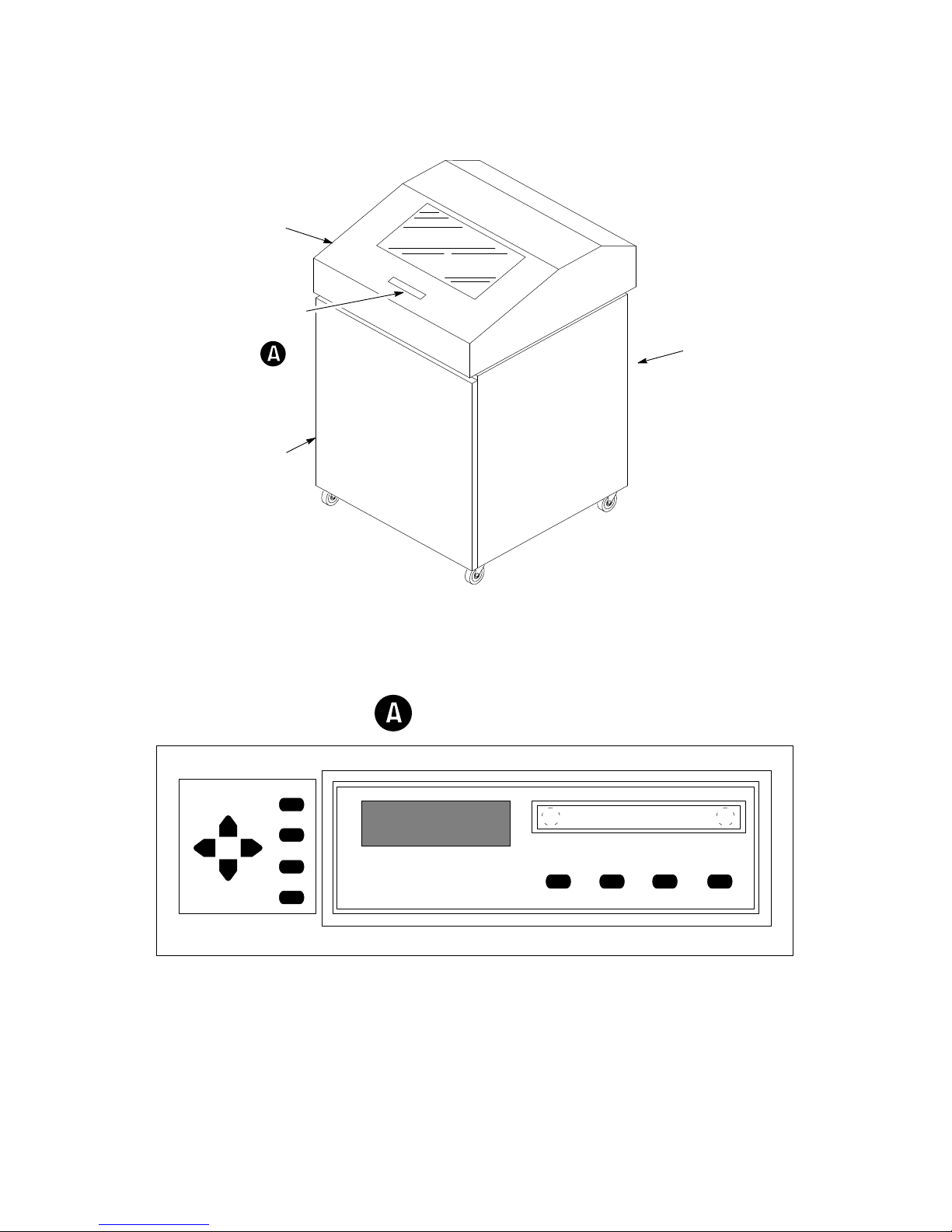
Printer Cover
Lift to open
Operator
Control
Panel
See Detail
Floor Cabinet
Front Door
Hinged on left.
Magnetic latch.
Open by pulling
right edge.
UP
NEXTPREV
SET TOF
DOWN
CLEAR
R/S
ENTER
Operator Control Panel
ON LINE FF VIEW
Rear Door
(Not shown)
Hinged on left.
Magnetic latch.
Open by pulling
right edge.
LF
Figure 1–1. Printer Cover, Door(s), and Operator Control Panel
1–5Maintenance Overview
Table 1–1. Electrical Controls and Indicators
Switch or
Indicator
Function
NOTE: Only the ON LINE switch operates when the printer is on–line.
All other switches operate only in the off–line state.
/O
Status lamps
Message display
ON LINE
FF Advances paper to top of form on next page.
LF
VIEW
UP
= On O = Off Turns printer on and off. Switch is
also a circuit breaker.
Illuminate when printer is on–line. Flash alternate-
ly to indicate fault. Off when printer is off–line.
Displays printer status and error messages.
T oggles the printer on–line and off–line.
Advances paper to top of next print line.
Advances paper for viewing through cover window, then returns paper to print position.
Locks and unlocks ENTER switch when pressed
simultaneously with DOWN switch. Also causes
display of configuration menus, submenus, and
diagnostic tests.
DOWN See above.
PREV
NEXT
CLEAR
R/S
SET TOF
ENTER
Displays previous parameter in a configuration or
diagnostic test menu.
Displays next parameter in a configuration or
diagnostic test menu.
Clears printer after a fault is corrected. Returns
printer to off–line state from within a configuration menu. Resets printer when pressed simultaneously with R/S switch.
Runs and stops configuration and self tests. Runs
and stops hex dump. Resets printer when pressed
simultaneously with CLEAR switch.
Sets location of first line of print on a page.
Enters displayed parameter into printer nonvolatile
memory . Must be unlocked before using.
1–6 Maintenance Overview
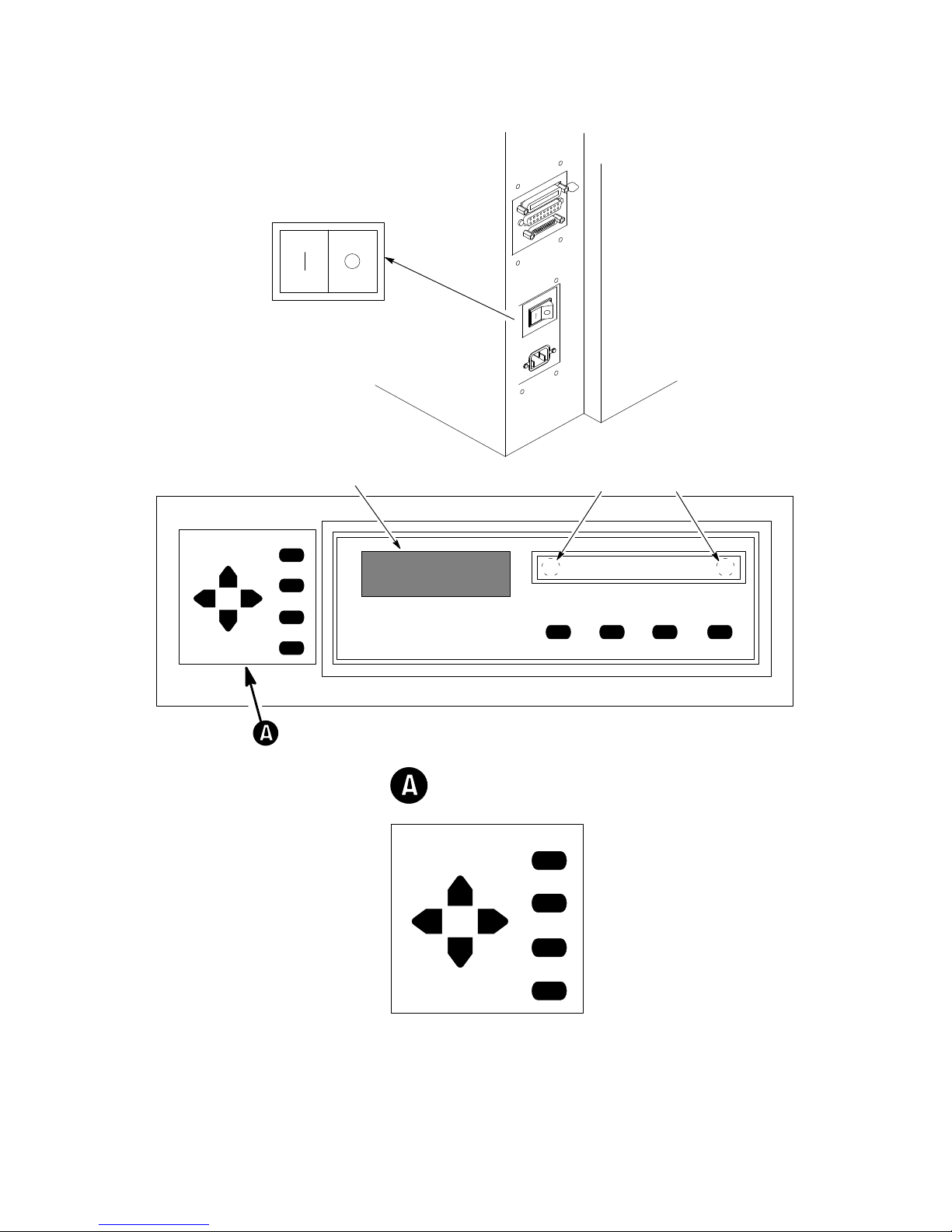
Power Switch
UP
DOWN
(On) (Off)
Status LampsMessage Display
CLEAR
R/S
NEXTPREV
SET TOF
ENTER
ON LINE FF VIEW
LF
Raise Printer Cover to
Access These Switches
CLEAR
UP
R/S
NEXTPREV
SET TOF
ENTER
DOWN
Figure 1–2. Electrical Controls and Indicators
1–7Maintenance Overview

Table 1–2. Mechanical Controls and Indicators
Control or
(See Figure 1–3)
FunctionIndicator
Forms thickness
lever
Forms thickness
pointer and scale
Tractors (2)
Tractor locks (2)
Horizontal
adjustment knob
Vertical position
knob
Sets platen for paper and forms of different thicknesses. Must be fully opened (raised) to load paper.
Indicates relative thickness of forms or paper. Set the
forms thickness lever at A for thin (single–part) forms,
B for thicker forms, and so on.
Hold and feed paper. Used to set left margin. Left tractor moves about one inch. Right tractor moves full
range.
Lock tractors in position.
Allows fine positioning of left print margins. Moves
paper left or right.
Used to set top of form or first line to be printed. Rotate
to move paper vertically.
1–8 Maintenance Overview
Horizontal
Adjustment
Knob
Tractor
Lock
Left Tractor Door
Right Tractor Door
Tractor
Lock
Vertical
Position
Knob
Forms Thickness
Lever and Scale
Forms Thickness Pointer
Figure 1–3. Mechanical Controls and Indicators
1–9Maintenance Overview
Tools, Test Equipment, and Supplies
The tools, test equipment, and supplies required for field level maintenance
of LG06 printers are listed in Table 1–3.
Table 1–3. Tools, Test Equipment, and Supplies
Item Part No.
Adhesive, Loctite 101854–002
Alcohol, anhydrous (must contain no water)
RTV silicone sealant
Adjustable wrench
Diagonal cutters
Digital voltmeter
Extension 3 in., 3/8 in. drive
Feeler gauge set
Force gauge
Gauge, platen position 996083–200
Kimwipes
Lubricant, bearing 101805–001
Nut driver set
Oscilloscope and probes (35 MHz or better)
Pliers, grip ring
Pliers, chain nose
Ratchet, 3/8 in. drive
Rule, steel, 6 in.
Screwdriver, torque, Utica TS–35
Adapter, 1/4 in. hex to 1/4 in. square, Utica HW–18
Hex bit, 3/16 in., torque screwdriver 29–20995–00
Hex bit, 3/32 in., torque screwdriver
Hex bit, 5/32 in., torque screwdriver
(Chatillon NY, Gauge–R, 0–20 lb)
(adhesive, methacryl)
(Lubriko M–3, Master Lubricant Co.)
–
101537–001
–
–
–
–
–
CAT 719–20
–
–
–
–
–
–
–
29–17381–00
29–24723–00
29–18505–00
24–18504–00
Hex bit, 5/64 in., torque screwdriver –
Screwdriver, Allen hex (set), w/extension
Screwdriver, Phillips
Screwdriver, Phillips
Screwdriver, slot
Screwdriver, slot
Socket, 7/16 in., 3/8 in. drive
T weezers –
1–10 Maintenance Overview
–
–
–
–
–
–

2 Scheduled Maintenance
Chapter Contents
Preventive Maintenance Checks and Services (PMCS) 2–2. . . . . . . . . . . . . . . . . .
Inspecting the Printer 2–3. . . . . . . . . . . . . . . . . . . . . . . . . . . . . . . . . . . . . . . . . . . . .
Cleaning the Printer 2–4. . . . . . . . . . . . . . . . . . . . . . . . . . . . . . . . . . . . . . . . . . . . . .
2–1Scheduled Maintenance
Preventive Maintenance Checks and Services (PMCS)
Perform preventive maintenance checks and services (PMCS) every six
months or after every 1000 hours of operation, whichever comes first.
Do these checks more often if the printer is used for heavy–duty, continuous
printing or if is located in a dusty area.
PMCS are listed in Table 2–1.
WARNING
Disconnect the ac power cord before performing PMCS. Failure to do so
could result in injury to you or damage to equipment.
Table 2–1. Preventive Maintenance Checks and Services
Interval Procedure
Every 6 months or 1000
hours of operation,
whichever occurs first.
Inspect the printer.
Clean the printer.
Check and adjust
platen gap.
Page
2–3
2–4
4–18
2–2 Scheduled Maintenance
Inspecting the Printer
Correct any condition found during inspection that could affect printer
performance or reliability.
Table 2–2. Physical Inspection
Item(s) to Inspect
Cabinet, base,
frame
Attaching
hardware
Nameplates
Printer cover,
cabinet door(s),
gas spring
assemblies
Hinges
Electrical
connectors
Controls and
indicators
What to Look For
Check for damage, cracks, breaks, dents, gouges, scratches,
delamination, warping, corrosion, and proper finish.
Inspect fasteners for thread damage, corrosion.
Inspect for legibility and damage.
Inspect for damage and loose or missing hardware. Check
that door(s) open/close without binding and stay closed.
Check that printer cover opens/closes smoothly and the gas
spring assemblies hold the cover open.
Inspect for damage and loose or missing hardware.
Inspect for damage, bent or broken pins.
Inspect for damage.
Windows
Ribbon cables
Circuit boards
Fans and motors
Inspect for breaks, cracks, or discoloration.
Inspect for broken wires, damaged insulation, pinched
wiring, etc.
Inspect for breaks, warping, evidence of overheated
components.
Inspect for obvious damage.
2–3Scheduled Maintenance

Cleaning the Printer
Do not use abrasive cleaners, particularly on the window. Do not drip
water into the printer. Damage to the equipment will result. When using
spray solutions, do not spray directly onto the printer; spray the cloth,
then apply the dampened cloth to the printer.
Cleaning Outside the Cabinet
1. Wipe the cabinet with a clean, lint–free cloth dampened (not wet) with
water and mild detergent or window cleaning solution.
2. Dry the cabinet with a clean, lint–free cloth.
3. Clean the inside of the cabinet. (See below.)
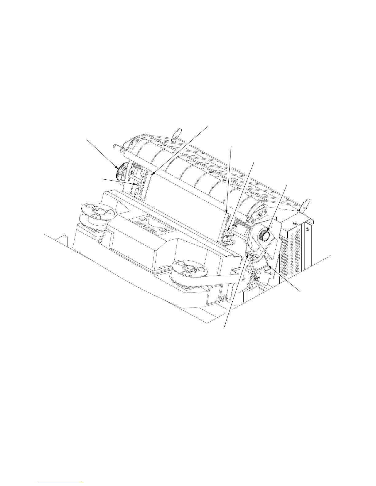
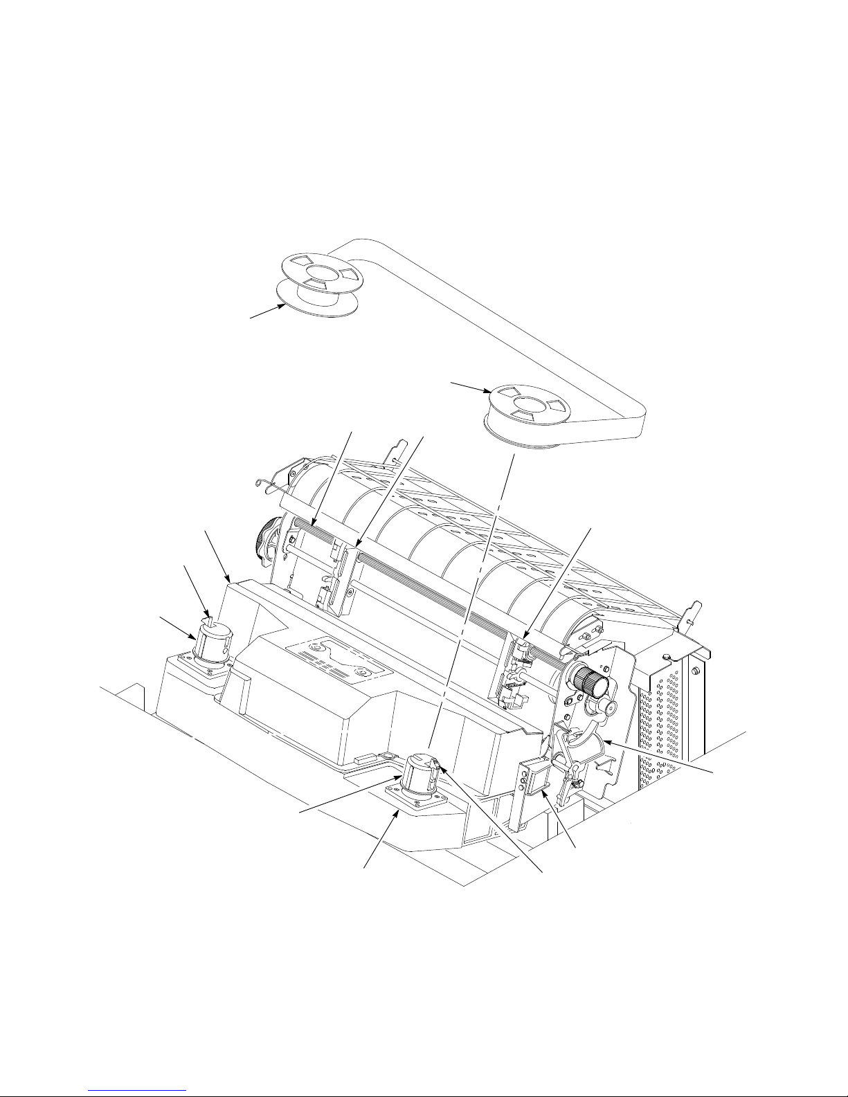
Cleaning Inside the Cabinet (Figure 2–1)
1. Set the power switch to the O (off) position.
CAUTION
2. Disconnect the ac power cord from the printer.
3. Open the printer cover.
4. Move the forms thickness adjustment lever (1) to the fully–open
position.
5. Remove paper from the printer.
6. Squeeze the locking latch (2) and lift the ribbon spools (3) from the
ribbon hubs (4).
7. Using a soft–bristled brush, wipe off paper dust and ribbon lint. Vacuum
up the residue. Pay particular attention to the tractors (5), shuttle cover
assembly (6), and base casting (7).
8. Wipe the splined shaft (8) with a soft cloth.
CAUTION
To avoid corrosion damage, use only anhydrous alcohol when cleaning
printer mechanical elements. The cleaning solution must contain no
water.
9. Using a cloth dampened with anhydrous alcohol, clean the ribbon guides
(9).
10. Vacuum up dust or residue that has accumulated inside the lower
cabinet.
2–4 Scheduled Maintenance
11. Wipe the lower cabinet interior with a clean, lint–free cloth dampened
with water and mild detergent or window cleaning solution.
12. Dry the cabinet interior with a clean, lint–free cloth.
13. Clean the shuttle assembly (page 2–6).
3
3
6
2
4
1. Forms Thickness Lever
2. Locking Latch (2)
3. Ribbon Spool (2)
4. Ribbon Hub (2)
5. Tractor (2)
6. Shuttle Cover Assembly
7. Base Casting
8. Splined Shaft
9. Ribbon Guide (2)
8
4
7
5
5
1
9
2
Figure 2–1. Cleaning Inside the Cabinet
2–5Scheduled Maintenance

Cleaning the Shuttle Frame Assembly (Figure 2–2)
1. Remove the shuttle cover assembly (page 5–24).
2. Remove the shuttle frame assembly (page 5–66).
3. Remove the paper ironer (page 5–44).
WARNING
Over time, the upper edge of the paper ironer can become sharp. To
avoid cutting yourself, handle the paper ironer on the sides.
4. Moisten a clean, soft cloth with anhydrous alcohol. Wipe the paper
ironer to remove lint, ink, and paper residue.
5. Install the paper ironer (page 5–44).
6. Remove the hammer bank cover assembly (1).
7. Moisten a clean, soft cloth with anhydrous alcohol. Wipe the hammer
bank cover assembly to remove lint, ink, and paper residue. Clean the
holes in the cover strips.
CAUTION
Use of excessive force can chip hammer tips.
8. Using a stiff, non–metallic brush (such as a toothbrush) and anhydrous
alcohol, carefully brush the hammer tips (2) to remove lint and ink
accumulations. Vacuum up any residue.
CAUTION
The hammer bank contains a strong magnet. To prevent damage to the
hammer tips, do not let the hammer bank cover assembly snap into
place as the hammer bank magnet attracts it. Any impact of the cover
against the hammer bank can break hammer tips.
9. With the thick plate facing the hammer bank, engage the hammer bank
cover assembly (1) on the alignment pins (3).
10. Rotate the hammer bank cover assembly (1) until it lies flush on the
hammer bank.
11. Check that the hammer bank cover assembly is properly positioned over
the alignment pins (3) and hammer tips.
12. Install the shuttle frame assembly (page 5–66).
13. Install the shuttle cover assembly (page 5–24).
14. Clean the card cage fan assembly (page 2–8).
2–6 Scheduled Maintenance
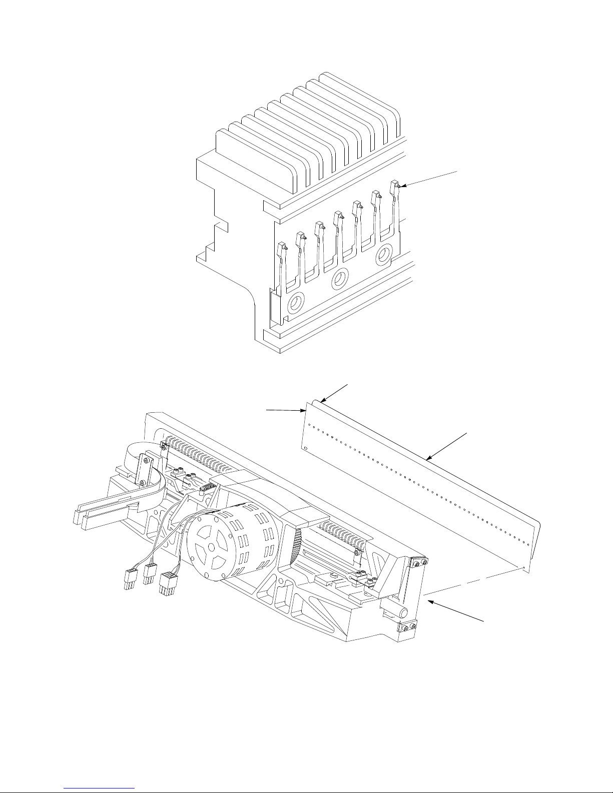
Thick plate
Thin plate
Hammer Tip
Hammer Bank
Cover Assembly
Roll pin (2)
(Not shown)
Figure 2–2. Cleaning the Shuttle Frame Assembly
2–7Scheduled Maintenance
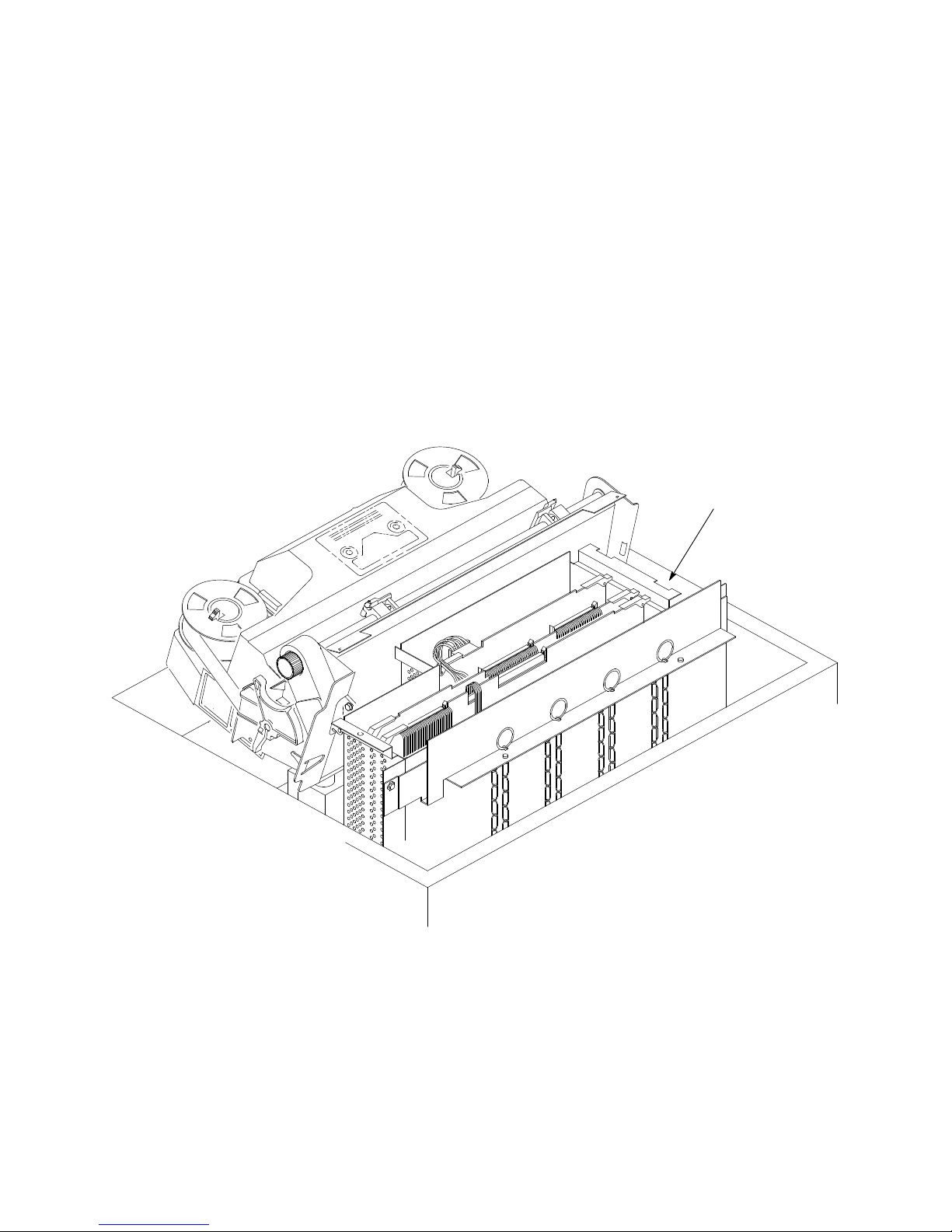
Cleaning the Card Cage Fan Assembly (Figure 2–3)
1. Open the printer cover.
2. Remove the paper guide assembly (page 5–42).
3. Vacuum the card cage fan assembly (1) and surrounding areas to remove
paper particles, dust, and lint.
4. Install the paper guide assembly (page 5–42).
5. Close the printer cover.
6. Connect the ac power cord to the printer.
Card Cage
Fan Assembly
2–8 Scheduled Maintenance
Figure 2–3. Cleaning the Card Cage Fan Assembly

3 Troubleshooting
Chapter Contents
Introduction 3–2. . . . . . . . . . . . . . . . . . . . . . . . . . . . . . . . . . . . . . . . . . . . . . . . . . . .
Fault Messages 3–2. . . . . . . . . . . . . . . . . . . . . . . . . . . . . . . . . . . . . . . . . . . . . . . . .
48 Volt Failed * 3–2. . . . . . . . . . . . . . . . . . . . . . . . . . . . . . . . . . . . . . . . . . . . . .
Dynamic RAM Fault 3–4. . . . . . . . . . . . . . . . . . . . . . . . . . . . . . . . . . . . . . . . . .
Ham. Bank Hot * 3–5. . . . . . . . . . . . . . . . . . . . . . . . . . . . . . . . . . . . . . . . . . . .
Ham. Coil Open * 3–6. . . . . . . . . . . . . . . . . . . . . . . . . . . . . . . . . . . . . . . . . . . .
Ham. Coil Short * 3–7. . . . . . . . . . . . . . . . . . . . . . . . . . . . . . . . . . . . . . . . . . . .
Ham. Drv. Short * 3–8. . . . . . . . . . . . . . . . . . . . . . . . . . . . . . . . . . . . . . . . . . . .
Mech Driver Hot * 3–9. . . . . . . . . . . . . . . . . . . . . . . . . . . . . . . . . . . . . . . . . . .
Mech Driver Link * 3–10. . . . . . . . . . . . . . . . . . . . . . . . . . . . . . . . . . . . . . . . . .
Paper Jam 3–11. . . . . . . . . . . . . . . . . . . . . . . . . . . . . . . . . . . . . . . . . . . . . . . . . .
Paper Out 3–12. . . . . . . . . . . . . . . . . . . . . . . . . . . . . . . . . . . . . . . . . . . . . . . . . .
Platen Open 3–13. . . . . . . . . . . . . . . . . . . . . . . . . . . . . . . . . . . . . . . . . . . . . . . . .
Ribbon Stall 3–14. . . . . . . . . . . . . . . . . . . . . . . . . . . . . . . . . . . . . . . . . . . . . . . .
Shttl Cover Open 3–15. . . . . . . . . . . . . . . . . . . . . . . . . . . . . . . . . . . . . . . . . . . . .
Shuttle Jam 3–16. . . . . . . . . . . . . . . . . . . . . . . . . . . . . . . . . . . . . . . . . . . . . . . . .
Software Error 3–17. . . . . . . . . . . . . . . . . . . . . . . . . . . . . . . . . . . . . . . . . . . . . . .
Symptoms Not Indicated by Fault Messages 3–18. . . . . . . . . . . . . . . . . . . . . . . . . .
Troubleshooting Aids 3–19. . . . . . . . . . . . . . . . . . . . . . . . . . . . . . . . . . . . . . . . . . . .
Diagnostic Self–Tests 3–26. . . . . . . . . . . . . . . . . . . . . . . . . . . . . . . . . . . . . . . . . . . .
Running the Diagnostic Self–Tests 3–28. . . . . . . . . . . . . . . . . . . . . . . . . . . . . . . . . .
Hex Code Printout 3–29. . . . . . . . . . . . . . . . . . . . . . . . . . . . . . . . . . . . . . . . . . . . . . .
3–1Troubleshooting
Introduction
This chapter contains procedures for troubleshooting printer malfunctions.
You must operate the printer to check printer performance, so have the User’s
Manual at the printer site. Although diagnostic test procedures are covered in
this chapter, basic printer operation is not covered.
Fault Messages
This section lists the fault messages that can appear on the control panel
display. The messages are listed in alphabetical order, followed by a
troubleshooting table.
If a fault condition occurs in the printer, the status lamps on the control panel
flash on and off and the first line of the display indicates “Fault Condition.”
The second line of the display indicates the specific fault.
There are two types of displayed faults:
• Operator correctable
• Field–service required, indicated by an asterisk (*) next to the fault
message
Test the printer after each corrective action. Stop maintenance when the
symptom disappears. Always press the CLEAR switch after correcting a
fault indicated by a fault message.
48 Volt Failed *
Instruction
1. Set power switch to O (off).
Wait 15 seconds. Set power
switch to 1 (on).
2. Press the CLEAR switch.
3. Remove paper guide
assembly (page 5–42).
IMPORTANT
Indication Yes No
“48 Volt Failed * ” message. Step 2. Return printer to
normal operation.
“48 Volt Failed * ” message. Step 3. Return printer to
normal operation.
—
Step 4.
—
3–2 Troubleshooting
Instruction NoYesIndication
4. Disconnect cable assembly
W1, CCB/Mech Driver, from
connector J1 on the CCB and
connector J6 on the Mech
Driver board.
5. Power up the printer.
6. Pull the Mech Driver board
up so that it clears the bottom
edge connectors.
7. Disconnect +5Volt connector
PS5 (cable assembly W2)
from the power supply board
and put a 1K Ohm resistor
between pins 1 and 2.
8. Remove the Mech. Driver
board.
—
Card cage fan comes on. Replace the
—
—
—
Step 5.
common controller
PCBA (page
5–46).
Step 7.
Step 8.
Step 9.
—
Reattach cable
assembly W1,
CCB/Mech Driver,
to connector J1 on
the CCB and
connector J6 on
the Mech Driver
board, and go to
step 6.
9. Power up the printer. Check
for +48 V at power supply
cable W3 connector PS: pin 8
= +48 V, pin 15 = ground.
(See Appendix D for cable
interconnections.)
10. Cycle power and check for
the fault message.
11. Cycle power and check for
the fault message.
12. Cycle power and check for
the fault message.
+ 48 Volts at pin 8. Replace the
mechanism driver
PCBA (page
5–48) and go to
step 10.
“48 Volt Failed * ” message. Replace cable
assembly W2,
+5V. (See
Appendix D.) Go
to step 1 1.
“48 Volt Failed * ” message. Replace cable
assembly W3, Hi
Voltage. (See
Appendix D.) Go
to step 12.
“48 Volt Failed * ” message. Replace cable
assembly W6,
P4980A Main
Wire Harness.
(See Appendix D.)
Replace the
power supply
PCBA (page
5–50) and go to
step 10.
Return printer to
normal operation.
Return printer to
normal operation.
Return printer to
normal operation.
3–3Troubleshooting

Dynamic RAM Fault *
Instruction
1. Set power switch to O (off).
Wait 15 seconds. Set power
switch to 1 (on).
2. Disconnect the input data line
from the host computer. Set
power switch to O (off). Wait
15 seconds. Set power switch
to 1 (on).
3. Make a Diagnostic Check of
the Microprocessors (page
3–21).
Indication Yes No
“Dynamic RAM Fault * ”
message.
“Dynamic RAM Fault * ”
message.
— — —
Step 2. Return printer to
normal operation.
Step 3. Return printer to
normal operation.
3–4 Troubleshooting
Ham. Bank Hot *
Instruction
1. Set power switch to O (off).
Wait 15 seconds. Set power
switch to 1 (on).
2. Press the CLEAR switch.
3. Run diagnostic self–test “All
Black” for 1/4 page (page
3–26).
4. Remove the shuttle cover
(page 5–24).
5. Install a magnet across the
hole in the base casting
where the cover open sensor
is mounted.
6. Run a diagnostic self–test
(page 3–26).
Indication Yes No
“Ham. Bank Hot * ” message. Step 2. Return printer to
normal operation.
“Ham. Bank Hot * ” message. Step 3. Return printer to
normal operation.
“Ham. Bank Hot * ” message. Step 4. Return printer to
normal operation.
—
—
Hammer bank fan operates. Replace shuttle
Step 5.
Step 6.
frame assembly
(page 5–66).
—
—
Replace hammer
bank fan
assembly (page
5–30).
3–5Troubleshooting
 Loading...