

Page 1

FBS Slip & Passbook Printer
LB12/LB15
Field Support Manual
Part Number: EK-A0685-SV002
Page 2

FBS Slip & Passbook Printer
LB12/LB15
Field Support Manual
Page 3

Acknowledgments
IBM, PC, AT and ProPrinter are registered trademarks of International Business Machines
Corporation.
Related manuals
LB12/LB15 Field Support Manual (including MSF) EK-LB125-SM
LB12/LB15 User’s Guide EK-LB125-UG
APP 6390 HSI (Hardware Software Interface) Manual AA-PYSXB-TE
APP 6390 Application Programmer's Guide AA-PTGWB-TE
APP 6390 Available Emulations Reference Manual AA-PYSWB-TE
This is a publication of DIGITAL EQUIPMENT BCFI AB
Printers and Peripherals
S-175 29 JÄRFÄLLA, Sweden
© Digital Equipment BCFI AB, 1997
All rights reserved. Reproduction in whole or in parts is prohibited without written consent of
the copyright owner. We have taken great care to ensure that the information in this manual
is correct and complete. However, if you discover any errors or omissions, or if you wish to
make suggestions for improvements, you are welcome to send your comments to us. Digital
Equipment BCFI AB disclaims any liability resulting from the use of this information and
reserves the right to make changes without notice.
Publication number: EK-A0685-SV002
First edition, issued October 1997 (all pages marked 9710)
Page 4

CONTENTS LB12/LB15 FIELD SUPPORT MANUAL
Chapter 1 GENERAL DESCRIPTION
Chapter 2 FUNCTIONAL DESCRIPTION
Chapter 3 MAINTENANCE
Chapter 4 SITE PREPARATION
9710 LB12/LB15 Field Support Manual i
Page 5

WARNINGS, CAUTIONS AND NOTES
WARNING!
This type of safety instruction is used where there is potential danger of injury to personnel
and/or damage to the equipment or the environment. The symbol inside the triangle
indicates the type of danger.
CAUTION!
This type of safety instruction is used where injury to personnel and/or damage to the
equipment or the environment can occur, if related instructions are not followed.
NOTE!
Notes are used to provide important or explanatory information.
9710 LB12/LB15 Field Support Manual ii
Page 6

CHAPTER 1 GENERAL DESCRIPTION
Pages 1-1 through 1-20
Section 1.1 INTRODUCTION
1.1.1 Printing characteristics..............................................................................................................1-3
1.1.2 Information feedback.................................................................................................................1-4
1.1.3 Maintenance aspects................................................................................................................1-4
1.1.4 Power ON/OFF..........................................................................................................................1-4
1.2 REMOVING THE COVER
1.3 THE DESIGN CONCEPT
1.4 TECHNICAL DATA
1.4.1 General print characteristics ....................................................................................................1-7
1.4.2 Document station......................................................................................................................1-8
Print area on vouchers...................................................................................................1-9
Print area on passbooks..............................................................................................1-10
Book thickness.............................................................................................................1-15
1.4.3 Power supply ..........................................................................................................................1-15
1.4.4 Diagnostic tests.......................................................................................................................1-15
1.4.5 Environmental conditions........................................................................................................1-15
1.4.6 Miscellaneous .........................................................................................................................1-16
1.4.7 Position Detection Facility.......................................................................................................1-16
1.4.8 Communications interface.......................................................................................................1-16
1.5 MAGNETIC STRIPE FACILITY
1.5.1 Design ..........................................................................................................................1-17
1.5.2 Performance ..........................................................................................................................1-19
1.5.3 Encoding technique.................................................................................................................1-19
1.5.4 Specifications 1-19
MSF read/write.............................................................................................................1-19
Printer dimensions with MSF device installed..............................................................1-19
Vertically folded passbooks .........................................................................................1-20
Horizontally folded passbooks.....................................................................................1-20
.............................................................................................................Page 1-3
.........................................................................................................1-5
..........................................................................................................1-6
...................................................................................................................1-7
..............................................................................................1-17
Figure
Table
1-1 The LB12/LB15 printers, exterior ..............................................................................................1-3
1-2 Removing the cover ..................................................................................................................1-5
1-3 Printer modules.........................................................................................................................1-6
1-4 Print area on vouchers..............................................................................................................1-9
1-5 Print area on vertically folded
1-6 Print area on vertically folded
1-7 Print area on horizontally folded passbooks ...........................................................................1-14
1-8 Measuring passbook thickness...............................................................................................1-15
1-9 The main parts of the MSF device ..........................................................................................1-18
1-10 Dimensions of vertically folded passbooks .............................................................................1-20
1-10 Dimensions of horizontally folded passbooks.........................................................................1-20
1-1 Print measurements on vouchers .............................................................................................1-9
1-2 Print measurements on vertically folded type A passbooks....................................................1-11
1-3 Print measurements on vertically folded type B passbooks....................................................1-13
type A
passbooks....................................................................1-10
type B
passbooks....................................................................1-12
9710 LB12/LB15 Field Support Manual 1-1
Page 7

1-2 LB12/LB15 Field Support Manual 9710
Page 8
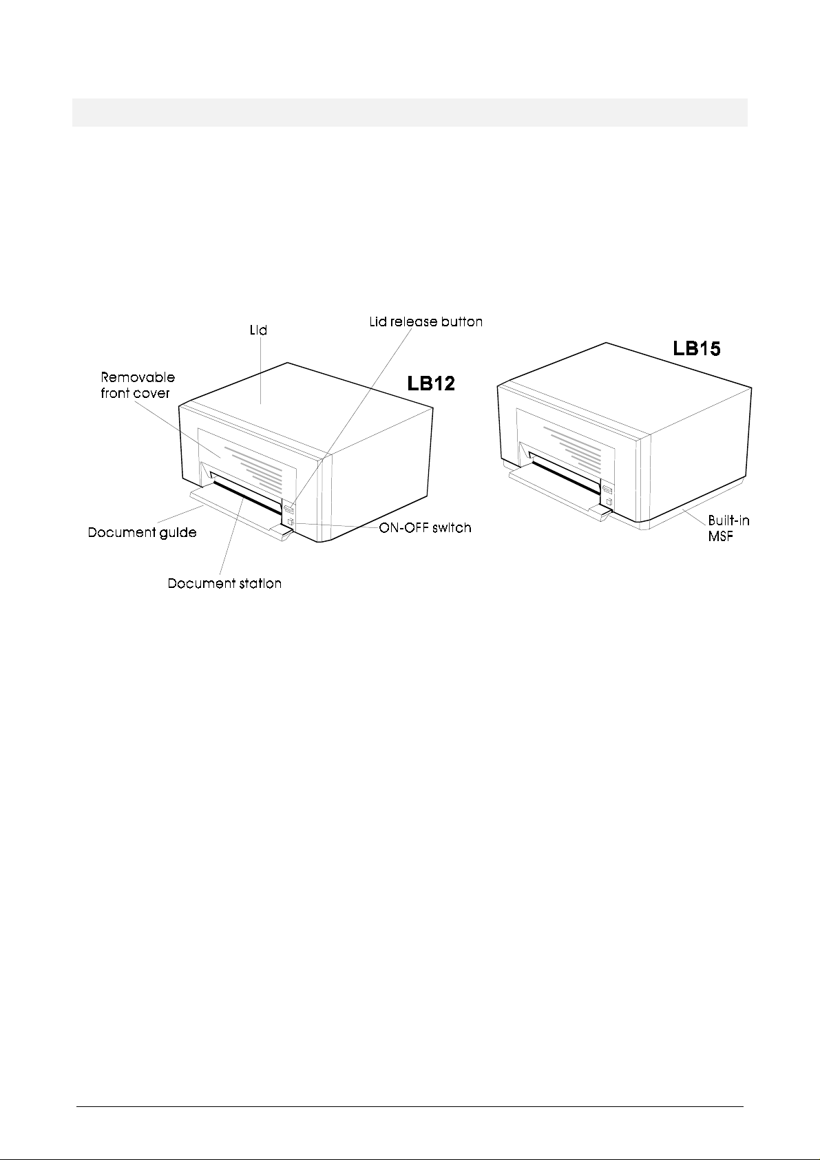
1.1 INTRODUCTION
The LB12 and LB15 Slip & Passbook Printers provide multi-functional document processing
in all-purpose workstations.
Figure 1-1 below shows the LB12/LB15. The printer is equipped with a
that can print on different types of documents such as single sheets, form sets, passbooks,
and passports, inserted horizontally through a slot at the front.
The document station can handle both vertically and horizontally folded passbooks or
passports. Printing is uni-directional or bi-directional and characters can be printed rotated
###
90
or upside down.
document station
1.1.1 Printing characteristics
On the LB12/LB15 printers, printing can take place at a speed of up to 300 characters per
second in both directions. The printer maintains the highest possible print speed by
automatically calculating the shortest possible route to the next print position. The position
of the 18-needle printhead can be controlled by the application program. The printer can
operate in its own Native mode or emulate an IBM ProPrinter III or IBM 4722.
When running in Native mode, the LB12/LB15 can use two character fonts and several
national character sets, including OCR-A and OCR-B fonts in PROMs. Other PROMs
providing logotypes and special character sets are optional. Additional character sets can
also be downloaded to the printer by the application program. When ProPrinter mode is
selected, the printer can use all the standard IBM ProPrinter III character generators.
A Position Detection Facility (PDF) can be used to find the left document edge.
Figure 1-1 The LB12/LB15 printers, exterior
9710 LB12/LB15 Field Support Manual 1-3
Page 9

1.1.2 Information feedback
The LB12/LB15 printers return a large amount of essential information to the application
program, including:
• printer configuration
• number of characters printed
• true status of execution
• error codes.
1.1.3 Maintenance aspects
The mechanical design is such that field replaceable modules can be replaced within five
minutes with no need for mechanical adjustments. The printers also have extensive built-in
test programs, significantly reducing the time spent on repairs.
1.1.4 Power ON/OFF
To reduce the amount of heat generated by the printer, the operator can switch the printer
from ON to STANDBY mode (and vice versa) by using the ON switch at the front of the
printer. The LB12/LB15 can also be switched OFF from the application program. The ON
switch, however, overrides software-controlled switching. The ON LED illuminates when the
printer is switched ON.
WARNING!
There is high voltage inside the PSU even when the printer is switched
off. REMOVE the power cable before you dismantle the PSU.
1-4 LB12/LB15 Field Support Manual 9710
Page 10
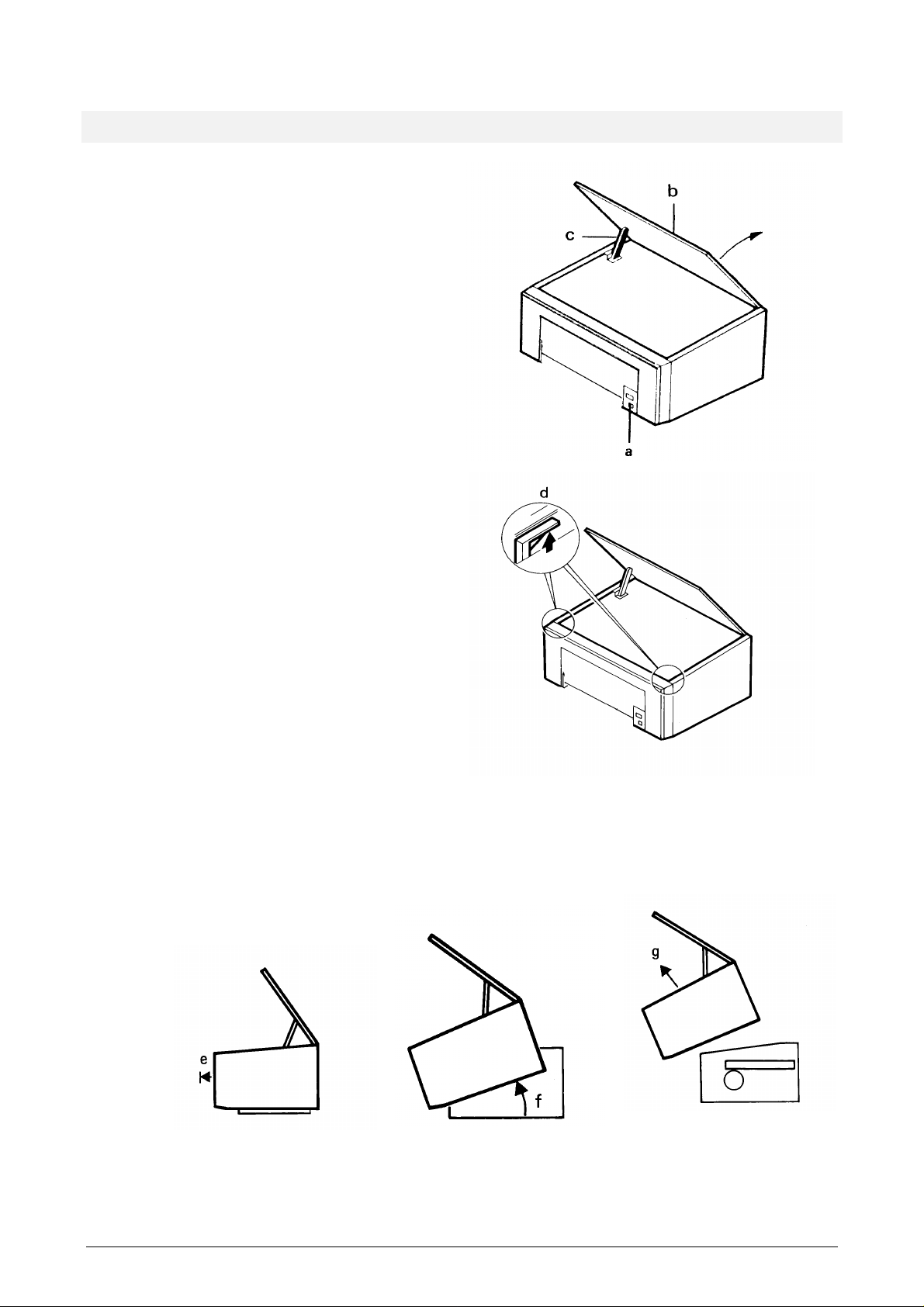
1.2 REMOVING THE COVER
1. Remove the front cover and the
document guide (see the
User's Guide
2. Press the lid release button (a).
3. Raise the lid (b) until the lid support
(c) snaps into the locked position.
4. Press the left side of the cover
backward whilst, at the same time,
lifting the cover latch (d) slightly,
using a screwdriver or similar tool.
With the latch lifted, pull the left side
of the cover forward a few
millimeters. Repeat on the right hand
side.
).
LB12/LB15
5. Pull the cover straight towards you as
far as possible (e).
6. Raise the cover as shown (f) and
remove it (g).
Figure 1-2 Removing the cover
9710 LB12/LB15 Field Support Manual 1-5
Page 11
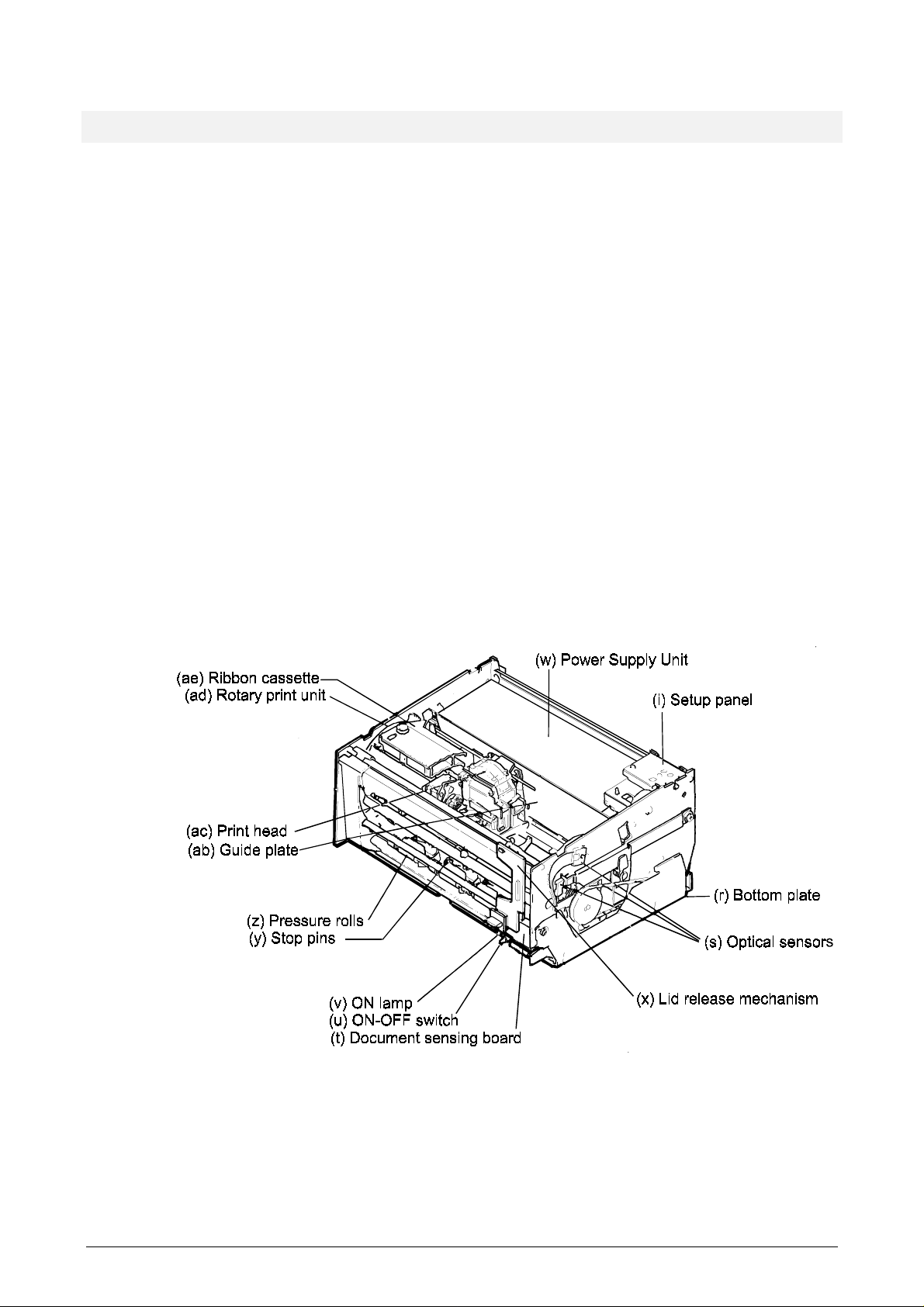
1.3 THE DESIGN CONCEPT
Each printer unit is built up between two side plates, joined by a base plate and various
bars and rods. The unit rests on a bottom plate (r) joined to the printer unit by means of two
screws. Rubber bushings and dampers reduce the transmission of vibrations to the bottom
plate and hence the printer cover.
The printhead (ac) is mounted on a carriage. The above parts and ink ribbon cassette (ae)
are all part of the rotary print unit (ad), which can rotate such that the printhead can be in
either a horizontal or a vertical position.
When a document is fed horizontally into the document station, the document stops against
a row of raised stop pins (y). Two optical sensors in the document station (t) detect that a
document is inserted and that it is in the correct position. The sensors are connected to the
document sensing board (t). A motor (not shown) lowers four pressure rolls (z) and removes
the stop pins. Four feed rolls, one under each pressure roll, feed the document into the print
position above a lower print bar (not shown).
Three optical sensors (s) are mounted on the outside of the right side plate. The upper
sensor senses when the rotary print unit is in the horizontal position. The middle sensor
detects when the printhead is in its extreme right position. The print unit cannot rotate
unless the printhead is in this position. The bottom sensor senses the position of the
pressure rolls and the stop pins. All sensors are connected to the document sensing board
(t) via optical fiber cables.
The ON lamp (v) and the ON-OFF switch (u) are mounted on the document sensing board
(t).
As a safety measure, printing cannot take place while the lid is open. An exception to this is
when the built-in tests are run.
Figure 1-3 Printer modules
The lid release mechanism (x) is mounted on the two shafts at the front. In addition to
raising the lid, this mechanism also handles the locking and release of the rotary print unit
in the LB12.
The main board (l) is mounted between the printer mechanism and the bottom plate (r). The
setup panel (i) can be replaced by an optional diagnostic panel.
1-6 LB12/LB15 Field Support Manual 9710
Page 12

1.4 TECHNICAL DATA
1.4.1 General print characteristics
Print method
Emulation
Print modes
Matrix
Resolution
Print speed Matrix Maximum print speed
Character pitches
(single-pass printing) Vertical 144 dots/inch.
Native mode Matrix Pitches
9x12 10, 12, 15, 16.5cpi
Impact dot matrix, 18-needle printhead.
IBM ProPrinter III
IBM 4722.
Alphanumeric, semi-graphics, graphics.
9x12, 18x36 (NLQ single pass), 18x72 (NLQ single pass, OCR)
Right character inclination (italic style) is available under software
control.
Horizontal 720 dots/inch.
Flash 514cps
Draft 300cps (Draft)
NLQ Up to 130cps
OCR-A, OCR-B 80cps
Fastfont 360cps
18x36 10, 12, 15, 16.5cpi, and proportional
18x72 10, 12, 15, 16.5cpi, and proportional
OCR-A 10cpi
OCR-B 10cpi
Flash 17.1cpi
ProPrinter and 4722 modes Matrix Pitches
9x12 10, 12, 17.1, 20cpi, and proportional
18x36 10, 12cpi, and proportional
Fastfont 12
Number of characters Pitch (cpi) Characters
per line
Input buffer
Standard character sets in PROM
Other character sets
(line length = 203mm) 10 80
12 96
15 120
16.5 132
5.5KB = approximately 5500 characters.
Native mode
ProPrinter and 4722 modes
Courier and Gothid type faces (NLQ 18x36 and DATA 9x12
qualities), always included in the printer.
ASCII Italian
German Swedish
British Norwegian/Danish
French Portuguese
Spanish Swiss
Code pages 437 and 850.
Other typefaces, fonts, logos etc. can be added as PROMs or
downloaded from the system.
9710 LB12/LB15 Field Support Manual 1-7
Page 13

1.4.2 Document station
Voucher dimensions
Passbook dimensions
Thickness
Paper weight
Width 90—235mm.
Height 67mm minumum (single sheet). The maximum
print height is 286mm, starting 4mm from the
upper edge.
Thickness 2mm maximum (original + 4 copies).
Width 100—235mm.
Height 75mm minimum. Maximum print height is
185mm from upper edge.
Quality 50—70 g/m², 0.08—0.16mm.
Other paper qualities must be tested.
OCR printing requires OCR specified paper
quality.
See description on Page 1-15.
Single voucher 45—110 g/m², 0.08—0.30mm
Voucher set 1 original: 45—90 g/m², 0.08—0.12mm.
4 copies: 40—60 g/m² each, 0.06—0.10mm.
4 carbons: 20-28 g/m² each.
Note If four copies are used, the lower
values must be followed. The binder
for the set can be placed on any side
or at the top.
Document feed
Single line (1/6”) 50ms.
Max. speed 0.4m/s = 95 lines/second.
1-8 LB12/LB15 Field Support Manual 9710
Page 14
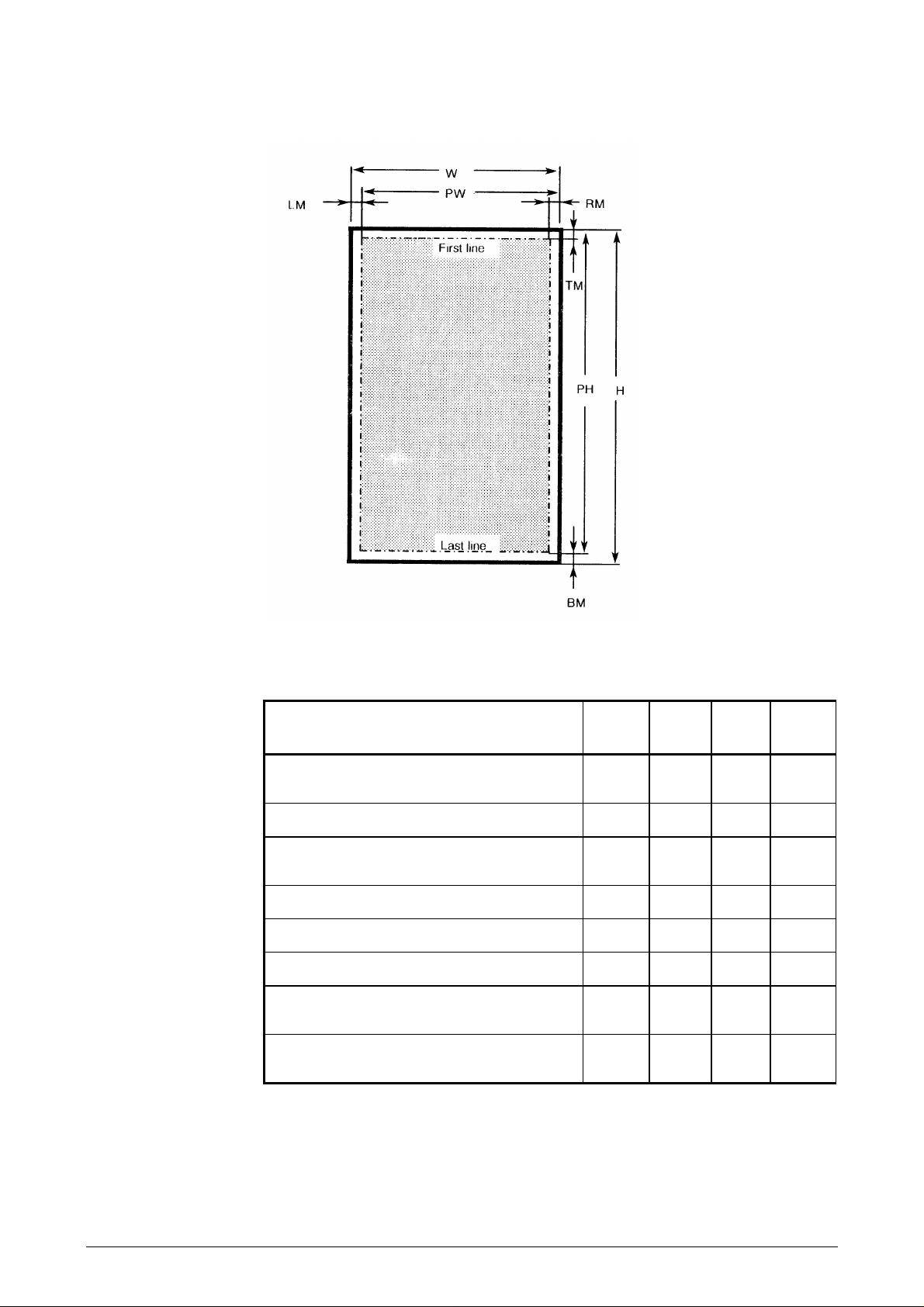
Print area on vouchers
H
W
PW
Document height 297 279 67 (See
Document width 210 216 90 235
Print width
(= leftmost print position)
RM
LM
PH
TM
Right margin 3 3 3 NA
Left margin 3 10 3 NA
Print height 287 269 61 291
Top margin (from top edge to top of
characters)
BM
Bottom margin (bottom edge to base of
characters)
NA = Not Applicable
Figure 1-4 Print area on vouchers
Measurement A4
(mm)
206 206 97 206
444NA
666NA
Letter
(mm)
Min.
(mm)
Max.
(mm)
Note)
Table 1-1 Print measurements on vouchers
The maximum document height is 318mm when using bottom synchronization, starting
4mm from the upper edge. The document height is infinite when using top synchronization
but PH is also maximized for top synchronization.
9710 LB12/LB15 Field Support Manual 1-9
Page 15
The above measurements include the binder (20mm wide) on either the short or long edge
in a form set. If the binder is placed on the right side, this reduces the line length. The
maximum number or lines is reduced if the binder is placed at the top.
Print area on passbooks
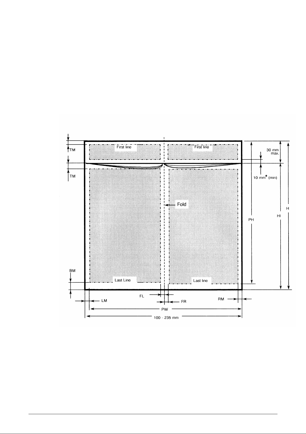
Both vertically and horizontally folded books can be used. Two types of vertically folded
passbooks can be specified:
• Type A Height is 122mm or more. Upper edge to be inserted first.
• Type B Height is less than 122mm and the book has cut inner pages. Lower
edge to be inserted first.
* No restrictions if pages are flipped over.
Figure 1-5 Print area on vertically folded
type A
passbooks
See the measurement table on the next page.
1-10 LB12/LB15 Field Support Manual 9710
Page 16

Measurement Printing (mm)
Min. Max.
H
HI
PH
PW
RM
LM
TM
BM
FL + FR
Book thickness NA 3.2
NA Not applicable
Height (no cut inner pages) 75 NA
Height, inner pages 75 NA
Print height 4 185
Print width NA 206
Right margin 3 NA
Left margin 3 NA
Top margin 4 NA
Bottom margin 8 NA
Fold margins 6 + 6 NA
Table 1-2 Print measurements on vertically folded type A passbooks
IMPORTANT !
The function of the document feed mechanism must be verified before books of different
widths are used in the same printer.
See Chapter 3, Maintenance, for information about adjusting the pressure rolls.
9710 LB12/LB15 Field Support Manual 1-11
Page 17
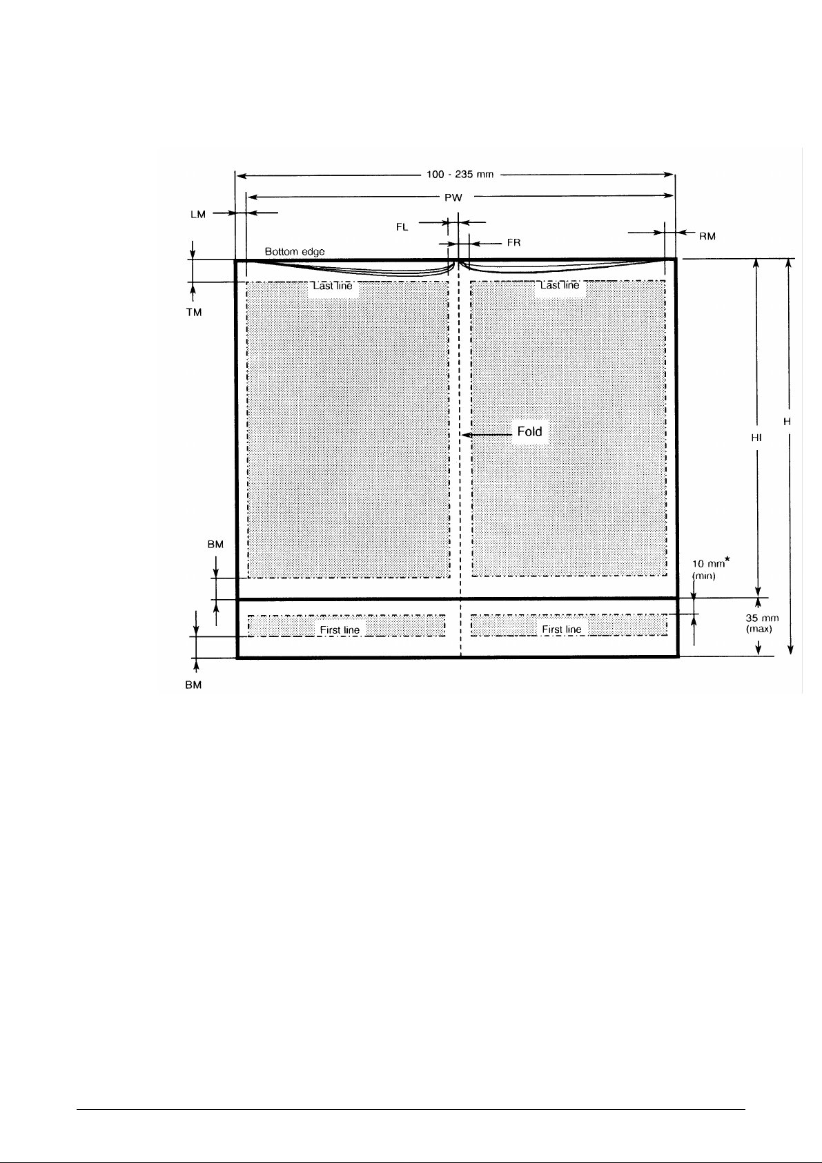
The book is turned upside down to ease paper feeding. The text is rotated 180°.
* No restrictions if pages are flipped over.
Figure 1-6 Print area on vertically folded
type B
passbooks
See the measurement table on the next page.
1-12 LB12/LB15 Field Support Manual 9710
Page 18

Measurement Min
(mm)
Max.
(mm)
H
HI
PH
PW
RM
LM
TM
BM
FL + FR
Height 75 NA
Height, inner pages 75 NA
Print height NA NA
Print width NA 206
Right margin 3 NA
Left margin 3 NA
Top margin 4 NA
Bottom margin 8 NA
Fold margins 6 + 6 NA
Book thickness NA 2.5
NA Not applicable
Table 1-3 Print measurements on vertically folded type B passbooks
IMPORTANT !
The function of the document feed mechanism must be verified before books of different
widths are used in the same printer.
See Chapter 3, Maintenance, for information about adjusting the pressure rolls.
9710 LB12/LB15 Field Support Manual 1-13
Page 19
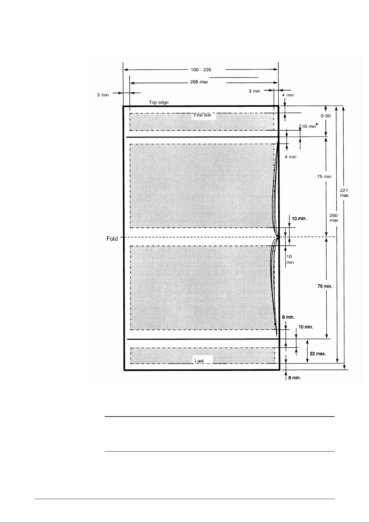
* No restriction if pages are flipped over.
Figure 1-7 Print area on horizontally folded passbooks
IMPORTANT !
The function of the document feed mechanism must be verified before passbooks of
differing widths are used in the same printer.
See Chapter 3, Maintenance, for information about adjusting the pressure rolls.
1-14 LB12/LB15 Field Support Manual 9710
Page 20

Book thickness
The thickness should be measured with a force of 200 N/m2 distributed over the passbook
surface.
1.4.3 Power supply
Figure 1-8 Measuring passbook thickness
Input voltage
Power dissipation
Power consumption
ON/OFF mode control
Input circuit fuse
Output voltage
1.4.4 Diagnostic tests
Automatic test
Other tests
1.4.5 Environmental conditions
87—132 V or 180—264 V, 50 or 60Hz auto ranging.
ON mode, not printing: 20 W
ON mode, printing: 150 W (peak load)
115 V 1.5 A
220 V 0.7 A
Manually, using switch on front panel.
One fast-acting, glass tube fuse, 6.3x32mm, 4 A.
+5.2 V, +36.5 V, and –12.5 V.
A power-ON test is performed at transition from standby to
ON mode. This test includes RAM and PROM tests,
movement of mechanical modules, checking of sensors, etc.
See Chapter 3,
Maintenance
.
Temperature
Operating +10— +35°C.
Storage –40— +70°C.
Humidity
Operating 20—80% RH, non-condensing.
Storage 20—90% RH, non-condensing.
9710 LB12/LB15 Field Support Manual 1-15
Page 21

1.4.6 Miscellaneous
Dimensions
Width 398mm.
Height, front LB12: 172mm; LB15: 192mm.
Height, back LB12: 195mm; LB15: 215mm.
Depth 300mm.
Weight
Acoustic noise
Operating Less than 60 dBA under any sound power level printing condition.
Standby Less than 40 dBA sound power level.
Ribbon
Type Cassette with endless loop. The ribbon is twisted 180° inside the
Length 2 x 28m (effective length).
Width 12.7mm.
Expected life More than 4x10⁶ characters. With OCR printing, more than
1.4.7 Position Detection Facility
Detects the left document edge.
(See also Chapter 4,
LB12: 14kg.
LB15: 15kg.
cassette on each turn.
2.8 x 10⁶ characters. The lower value is due to a higher degree of
inking.
Site Preparation
.)
1.4.8 Communications interface
See the
LB12/LB15 User's Guide
.
1-16 LB12/LB15 Field Support Manual 9710
Page 22

1.5 MAGNETIC STRIPE FACILITY
The MSF (Magnetic Stripe Facility) is a device in the LB15 printer. This device enables the
printer to read and write a track of magnetically encoded characters positioned on the back
cover of a passbook.
1.5.1 Design
The main part of the MSF device is a read/write (R/W) head that can be moved sideways in
a wide slot at the bottom of the document path. A black plastic panel covers the slot when
the head is in its home position on the right side. The panel moves away, exposing the head
during the read/write operation.
Passbooks must be inserted manually into the document station, aligned with the right side
of the insertion slot. The book must be open with the printable pages facing upward and the
outside of the cover downward. The magnetic stripe is then positioned as far as possible to
the right.
The MSF mechanics are built into the bottom plate assembly (see Figure 1-9).
The main MSF parts are:
• MSF logic board "piggy-back" mounted on the main board.
• Document guide with increased height (standard MSF version or MSF version with
operator panel).
• Printer bottom plate assembly with increased height compared to the bottom plate used
in the LB12
• Interconnecting cables between the MSF mechanics and the MSF logic board.
9710 LB12/LB15 Field Support Manual 1-17
Page 23

Figure 1-9 The main parts of the MSF device
1-18 LB12/LB15 Field Support Manual 9710
Page 24

1.5.2 Performance
Data recording is performed in accordance with the DIN 32744/ISO 8484 standards.
Usually, data recording is carried out in accordance with the DIN 32744 standard, which
means that a string of maximum 48 characters is written twice (i.e. the basic string followed
by a duplicate) in a single track on the magnetic stripe.
Recording in accordance with the ISO 8484 standard means either that a string of up to 108
characters is written or that a string of up to 48 characters is written twice (i.e. as defined by
the DIN 32744 standard).
Non-standard start and stop sentinels can be selected from the application.
Read after write is always performed to check that the string has been recorded correctly.
After a duplicate recording, both strings (or records) are read and compared to ensure that
they are equal.
Reading and writing is performed while the R/W head moves at constant speed. Writing is
performed when the R/W head moves from right to left whereas reading can be performed
in any direction.
1.5.3 Encoding technique
The encoding technique used is the F/2F encoding system, which allows serial recording of
self-clocking data. This means that the data string comprises both data bits and clock
signals. A flux transition occurring between clocks signifies a ONE, whereas the absence of
such a flux transition signifies a ZERO.
The data is recorded as a continuous sequence of characters with no inter-character gap.
The data string is both preceded and followed by at least 20 synchronizing ZERO bits. In
the event of of duplicate recording, the inter-record gap consists of at least 60 ZERO bits.
1.5.4 Specifications
MSF read/write
Packing density
Read/write speed
Return speed
Number of tracks
Number of characters
Character I/O format
Parity
Transaction time
Printer dimensions with MSF device installed
210 bits per inch ±5%.
8 inches per second.
8 inches per second.
1.
108 maximum (excluding pre- and post-amble).
5 bits (4 data + 1 parity bit), LSB first.
Odd.
2.5 s approx. (2 forward + 2 backward movements).
Height, front
Height, back
Document guide depth
9710 LB12/LB15 Field Support Manual 1-19
197mm.
215mm.
96 mm.
Page 25
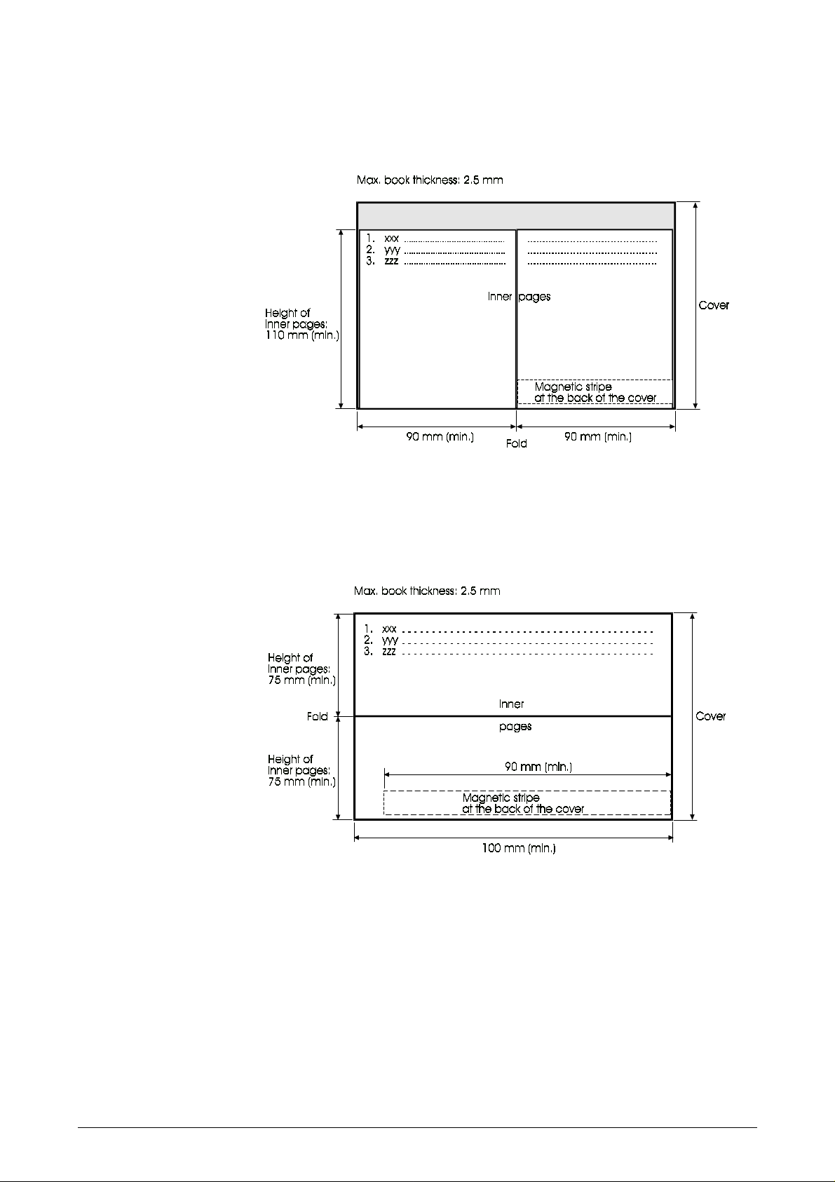
Vertically folded passbooks
Inner pages can be shorter than the passbook cover.
Figure 1-10 Dimensions of vertically folded passbooks
Horizontally folded passbooks
Inner pages must not be smaller than the passbook cover.
Figure 1-11 Dimensions of horizontally folded passbooks
1-20 LB12/LB15 Field Support Manual 9710
Page 26

CHAPTER 2 FUNCTIONAL DESCRIPTION
Pages 1-1 through 1-40
Section 2.1 MAIN FUNCTIONAL PARTS
2.1.1 Document grasp and feed mechanisms....................................................................................2-3
Pressure rolls mechanism .............................................................................................2-4
Stop pin mechanism ......................................................................................................2-4
Home position................................................................................................................2-5
Inserting a document against the outer stop pins..........................................................2-5
2.1.2 Rotary print unit.........................................................................................................................2-8
2.1.3 Lateral carriage movement .......................................................................................................2-9
2.1.4 Ribbon feed ..........................................................................................................................2-10
2.1.5 Rotary print unit release and locking.......................................................................................2-11
2.1.6 Printhead-to-paper distance control (PDC) mechanism..........................................................2-12
Mechanism design.......................................................................................................2-12
Head attach and release..............................................................................................2-13
Auto calibration............................................................................................................2-15
Document printing........................................................................................................2-15
Passbook printing ........................................................................................................2-16
PDC cam wheel...........................................................................................................2-16
Sensor element............................................................................................................2-18
2.1.7 PDF - Position Detection Facility.............................................................................................2-19
2.1.8 Main board ..........................................................................................................................2-19
General........................................................................................................................2-19
Carriage motor drive circuits........................................................................................2-20
Stepper motor control and drive circuits ......................................................................2-20
Power ON/OFF logic....................................................................................................2-20
2.1.9 Capacitor board.......................................................................................................................2-20
2.1.10 Printhead board.......................................................................................................................2-20
2.1.11 Opto sensors ..........................................................................................................................2-20
General........................................................................................................................2-20
PDF sensor..................................................................................................................2-22
Sensor calibration........................................................................................................2-23
2.1.12 Joint board ..........................................................................................................................2-23
2.1.13 PSU and voltage Indicator......................................................................................................2-23
2.1.14 Diagnostic panel (optional)......................................................................................................2-24
2.1.15 Set-up panel ..........................................................................................................................2-24
..........................................................................................Page 2-3
2.2 PRINCIPLES OF PRINTING
2.2.1 Printhead ..........................................................................................................................2-27
2.2.2 Character formation ....................................................................................................... .........2-27
2.2.3 Character repertoires and character sets................................................................................2-28
2.2.4 Character sets.........................................................................................................................2-29
2.2.5 Character generation ...................................................................................................... ........2-29
2.2.6 Graphic character representation............................................................................................2-32
2.2.7 Logotypes ..........................................................................................................................2-32
2.2.8 IBM ProPrinter III emulation....................................................................................................2-32
2.3 STEPPER MOTOR DRIVE PRINCIPLES
2.3.1 General ..........................................................................................................................2-33
2.3.2 General motor drive principles................................................................................................2-33
2.3.3 Stepper motor drive in the LB12/LB15 printers.......................................................................2-35
2.4 NEEDLE FIRING PRINCIPLES
2.5 FIRMWARE STRUCTURE
2.6 MEMORY USAGE
..................................................................................................................2-36
...................................................................................................2-27
...............................................................................2-33
..............................................................................................2-35
......................................................................................................2-35
9710 LB12/LB15 Field Support Manual 2-1
Page 27

2.7 MAGNETIC STRIPE FACILITY ..............................................................................................2-37
2.7.1 Mechanics ..........................................................................................................................2-37
2.7.2 Electronics ..........................................................................................................................2-38
Reading........................................................................................................................2-38
Writing..........................................................................................................................2-39
Control register ............................................................................................................2-39
Configuration/status register........................................................................................2-39
Stepper motor control ..................................................................................................2-39
Figure 2-1 Document feed mechanism......................................................................................................2-3
2-2 Pressure rolls mechanism.........................................................................................................2-4
2-3 Stop pin mechanism..................................................................................................................2-4
2-4 Feed rolls and stop pins in home position.................................................................................2-5
2-5 The document being fed in........................................................................................................2-5
2-6 The feed motor starting to feed in the document ......................................................................2-6
2-7 Lowering the rear pressure rolls................................................................................................2-6
2-8 The front pressure rolls raised to let the document pass on its way out ...................................2-7
2-9 Front pressure rolls lowered to complete the document release ..............................................2-7
2-10 The document station ready for another document ..................................................................2-8
2-11 Print unit position sensor (V-H sensor) .....................................................................................2-9
2-12 Carriage drive mechanism ........................................................................................................2-9
2-13 Ribbon drive mechanism.........................................................................................................2-10
2-14 Carriage in its extreme right position releases the print unit ...................................................2-11
2-15 Printhead-to-paper distance mechanism in document position ..............................................2-12
2-16 Printhead-to-paper mechanism in book position.....................................................................2-13
2-17 Head attach position for passbook printing.............................................................................2-14
2-18 Head release short position ....................................................................................................2-14
2-19 Home position (= head release long)......................................................................................2-14
2-20 The PDC cam wheel ...............................................................................................................2-16
2-21 PDC sensor output voltage .....................................................................................................2-17
2-22 PDC sensor element...............................................................................................................2-18
2-23 Light-reflecting opto-sensor.....................................................................................................2-21
2-24a Light-breaking opto-sensors....................................................................................................2-21
2-24b Document edge opto-sensor...................................................................................................2-21
2-24c AIF opto-sensor........................................................................................................... ............2-21
2-25 Opto-sensor logic.................................................................................................................... 2-22
2-26 Diagnostic panel......................................................................................................................2-24
2-27 LB12/LB15 block diagram.......................................................................................................2-25
2-28 Printhead needle arrangement................................................................................................2-27
2-29 Character formation in high quality printing.............................................................................2-27
2-30 Character formation at 300cpi print speed..............................................................................2-28
2-31 Character repertoires and character sets................................................................................2-29
2-32 Character code table layout ....................................................................................................2-30
2-33 Code extension principles.......................................................................................................2-31
2-34 Selecting a character set......................................................................................................... 2-32
2-35 Simplified description of the stepper motor function ...............................................................2-34
2-36 MSF mechanics ......................................................................................................................2-37
2-37 Data read signal timing diagram .............................................................................................2-38
2-38 MSF block diagram .................................................................................................................2-40
Table 2-1 Printhead positions and related CPU commands ...................................................................2-13
2-2 Memory configuration..............................................................................................................2-19
2-3 Memory usage ........................................................................................................................2-36
2-2 LB12/LB15 Field Support Manual 9710
Page 28
2.1 MAIN FUNCTIONAL PARTS
This chapter starts with a description of the main mechanical and electromechanical
functions. This will give you a good understanding of the interface between the electromechanics on the one hand, and the electronics and the hardware-software interactions on
the other hand. This is followed by an overall description of the circuit board assemblies and
the connected devices. The chapter concludes with descriptions of the mechanical and
electronic functions of the Magnetic Stripe Facility.
2.1.1 Document grasp and feed mechanisms
These mechanisms control the insertion, grasping, bi-directional transport, and release of
documents inserted into the document station.
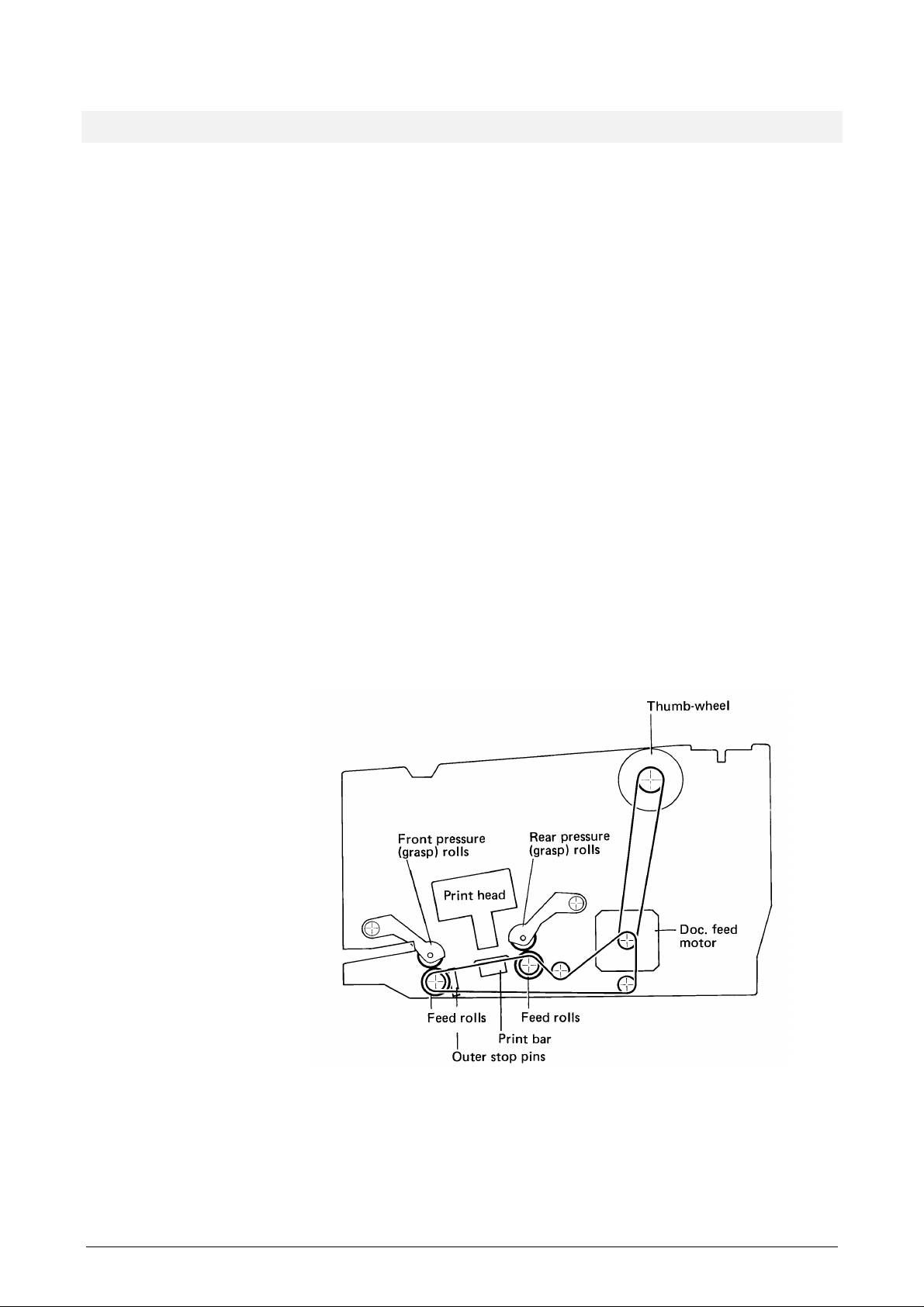
The document feed motor drives the front and rear feed rolls. The front and rear pressure
rolls can be lowered to press the document against the feed rolls when the document is to
be grasped and fed in either direction. A line of stop pins helps the operator to align the
document. Both the pressure rolls and the stop pins are controlled by the grasp motor (not
shown). A sensor outside the printer's right side plate (not shown) senses the current
position of the stop pins.
The document station has the following document sensors (not shown) ensuring that the
document is in the correct position before document feeding starts:
• outer edge sensor positioned just outside the outer stop pins
• right-edge sensor
• Automatic Insertion Function (AIF) sensor.
Figure 2-1 Document feed mechanism
The thumbwheel near the setup/diagnostic panel can be used to retrieve a document that
has become trapped inside the printer.
9710 LB12/LB15 Field Support Manual 2-3
Page 29
Pressure rolls mechanism
The mechanisms for the pressure rolls and the stop pins are shown in more detail in the
following two figures.
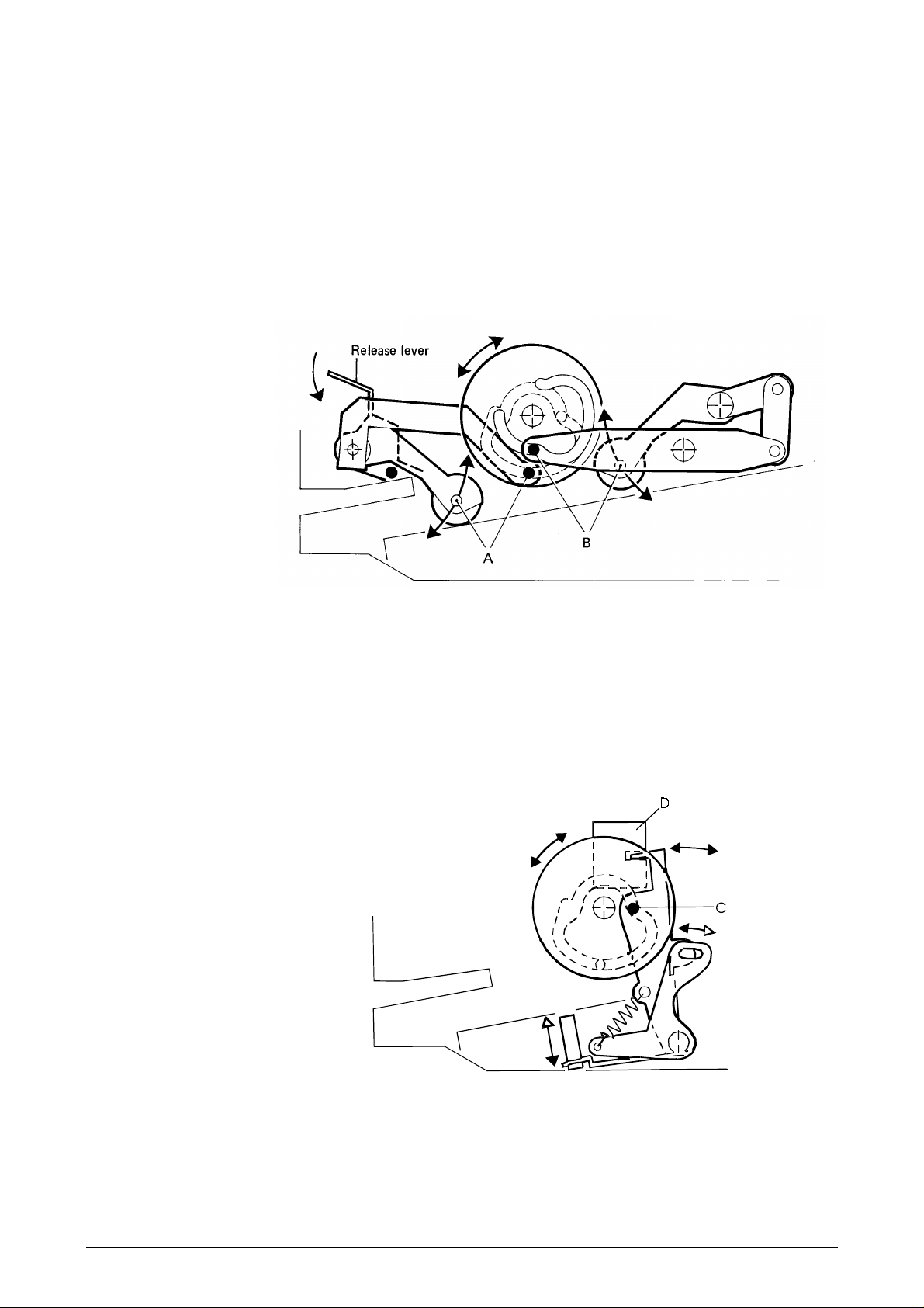
A cam wheel with two grooves controls both mechanisms. The grasp motor turns the cam
wheel, via a toothed belt, to six clearly-defined positions. One of the grooves moves the
outer pressure rolls (grasp rolls) up and down via an arm (A). The other groove controls the
inner pressure rolls via another arm (B). If you need to remove a jammed document, you
can lift the outer pressure rolls further by pressing the release lever down.
Stop pin mechanism
A third arm (C), which follows the same groove as arm (A), directly controls the movement
of the stop pins. This arm also controls the stop pins via a tension spring. When the stop
pins are lowered, the upper part of arm (C) interrupts the light in the opto-sensor (D) which
signals to the CPU that the document path is free.
Figure 2-2 Pressure rolls mechanism
Figure 2-3 Stop pin mechanism
2-4 LB12/LB15 Field Support Manual 9710
Page 30
Home position
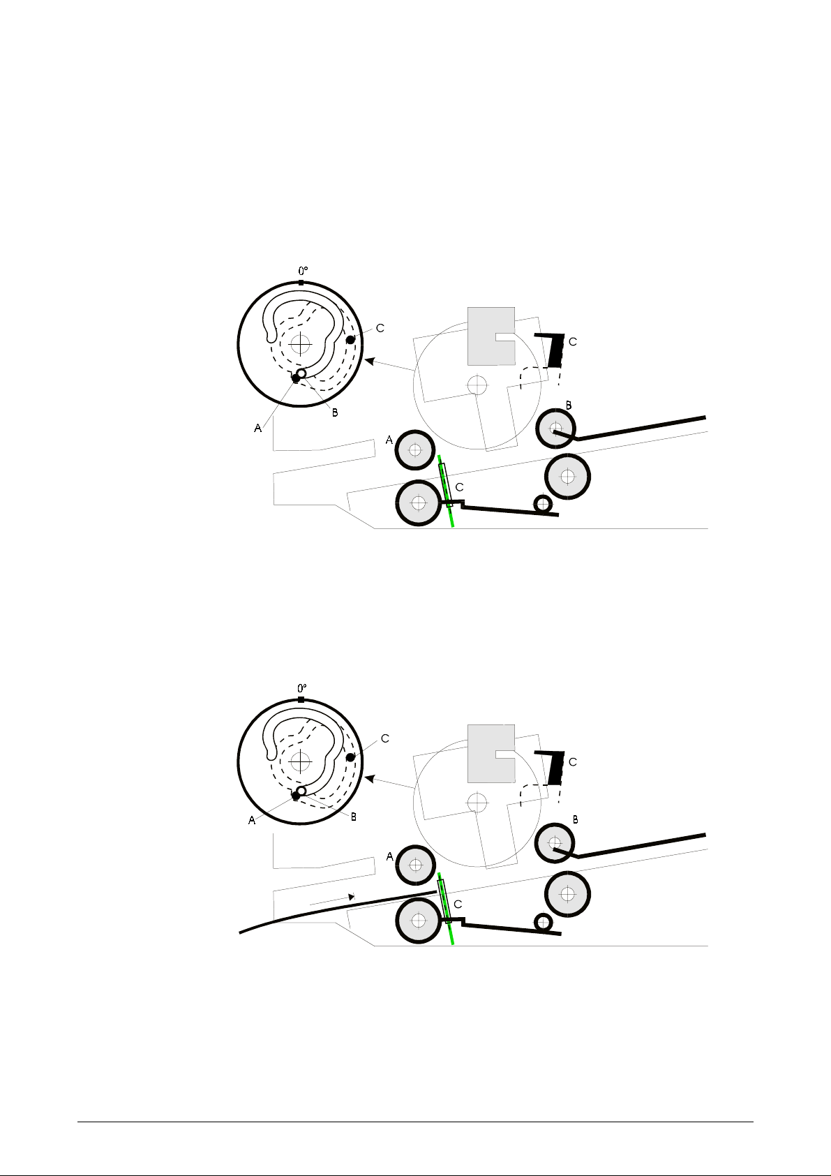
The figure below shows the basic position of the relevant mechanisms. The pressure rolls
(A) and (B) are lifted, and both the outer and inner stop pins (C) are raised.
The application knows which type of document is to be inserted and may have informed the
operator by means of an on-screen message. Alternatively, the operator may have informed
the application, via the keyboard, regarding the type of document he or she is going to
insert.
Figure 2-4 Feed rolls and stop pins in home position
Inserting a document against the outer stop pins
Thin documents, such as forms and vertically folded passbooks, should be inserted against
the outer stop pins, as shown below.
Figure 2-5 The document being fed in
9710 LB12/LB15 Field Support Manual 2-5
Page 31

The document sensors are activated when the document is in the correct position. The cam
wheel turns 90 degrees, lowering the front feed rolls (A) grasping the document. The turning
of the cam wheel also lowers all the stop pins (C). The opto-sensor (C) is activated.
The feed motor starts and feeds the document into the printer.
The application program decides when the printhead is to be lowered to start printing.
Figure 2-6 The feed motor starting to feed in the document
The cam wheel turns a further 30 degrees, lowering the rear pressure rolls. The rear feed
rolls now take part in feeding the document.
Figure 2-7 Lowering the rear pressure rolls
2-6 LB12/LB15 Field Support Manual 9710
Page 32

When printing is complete, the cam wheel turns a further 80 degrees, lifting the front
pressure rolls to allow the bottom edge of the document to pass on its way out.
Figure 2-8 The front pressure rolls raised to let the document pass on its way out
When the bottom edge passes the outer edge sensor, the cam wheel returns to the 120
degrees position, thus lowering the front pressure rolls to achieve the complete release of
the document.
Figure 2-9 Front pressure rolls lowered to complete the document release
9710 LB12/LB15 Field Support Manual 2-7
Page 33

The cam wheel then returns to its home position, raising all feed rolls and stop pins. The
document station is now ready to receive another document.
Figure 2-10 The document station ready for another document
2.1.2 Rotary print unit
The rotary print unit is built up between two side plates interconnected by means of a front
and a rear guide shaft, along which the carriage moves.
The printhead is mounted on the carriage by means of metal leaf springs. A wire spring
pushes the printhead towards the print bar. A PDC mechanism, comprising a stepper motor
and a cam wheel can, via a tie-rod, pull the printhead away from the printbar to a number of
different positions.
The print unit can be turned to two fixed positions as follows:
Vertical position, used for:
• sensing the left paper edge, using the Position Detection Facility (PDF) in the
document station
• printing in the document station.
Horizontal position, used for:
• ink ribbon cassette replacement.
See Page 2-11 for information about the print unit release and locking mechanism.
2-8 LB12/LB15 Field Support Manual 9710
Page 34

An opto-sensor detects when the print unit is in its horizontal position.
Figure 2-11 Print unit position sensor (V-H sensor)
2.1.3 Lateral carriage movement
The carriage is driven laterally by a stepper motor via a toothed belt clamped to the carriage
with a belt clamp.
Figure 2-12 Carriage drive mechanism
9710 LB12/LB15 Field Support Manual 2-9
Page 35

The printer uses the carriage movement:
• to detect the left paper edge
• to print while the carriage moves
• to tabulate by moving the carriage to defined positions
• to move the carriage to a specific position during calibration of the automatic printhead-
• to change between book and document mode by moving the carriage to its extreme
• to feed the ink ribbon.
The CPU generates two 90 degree phase-shifted pulse trains, which move the carriage
motor. The frequency of the pulse trains increase or decrease according to tables stored in
memory during acceleration or decceleration or at constant speed.
2.1.4 Ribbon feed
The ribbon drive mechanism consists of a gear transmission, with a drive pin entering the
ink ribbon cassette. The gear is driven indirectly, via an O-ring, by the carriage motor, using
the same toothed belt used to drive the carriage. The drive pin rotates in the same direction
regardless of the direction of the carriage movement.
to-paper distance control function
right or left hand position
Figure 2-13 Ribbon drive mechanism
2-10 LB12/LB15 Field Support Manual 9710
Page 36

2.1.5 Rotary print unit release and locking
A pin (a), mounted on a spring-loaded locking arm (b), is pressed into a hole in the right
side plate of the print unit, to hold the print unit accurately in position during printing. The
conical-shaped end of the pin enters the hole only partly, thus eliminating any free play.
There is one hole each for the horizontal and the vertical position.
When the print unit is to rotate, the carriage moves as far as possible to the right side,
where it pushes a small rod (c) against the locking arm, thus disengaging the locking pin.
The front end of the locking arm then leaves the gap of an opto-sensor (d), signaling to the
CPU that the print unit can be rotated.
Figure 2-14 Carriage in its extreme right position releases the print unit
At the end of the rotation, the carriage moves slightly to the left to enable the locking pin to
lock the unit in its new position. Due to mechanical tolerances, the stepper motor may add
some extra motor steps until the latch pin enters the locking position. The opto-sensor
senses that the locking pin is engaged.
The locking pin locks the print unit in the vertical or horizontal position only.
When changing from the vertical to the horizontal position, pressing the
the carriage, releasing the locking pin for 10 seconds. A separate latch, controlled by the lid
release mechanism, locks the print unit in its vertical position. When the lid release button is
pressed within the 10 seconds, this latch unlocks and a tension spring pulls the print unit to
the horizontal position.
To return the print unit to the vertical position, press the
has released the locking pin, rotate the print unit manually until the latch snaps into the
locked position.
step switch
step switch
and, when the carriage
moves
9710 LB12/LB15 Field Support Manual 2-11
Page 37

2.1.6 Printhead-to-paper distance control (PDC) mechanism
Mechanism design
A wire spring, fitted under the carriage, pushes the printhead towards the print bar. The
PDC stepper motor, with its cam wheel, can pull the printhead away from the print bar to a
number of defined positions by means of the tie rod connected to the cam wheel.
A sensor arm with a nose wheel is fitted to the front of the printhead. The slide shown in the
figure decides how far the nose wheel can be pushed in. When the slide is in its left
position, called the
the nose. With the slide in the correct position, called the
extend 0.5—1.2mm. A sensor indicates the position of the nose wheel in relation to the
printhead nose. The sensor comprises a permanent magnet, fitted to the end of the sensor
arm, and a Hall element. The output voltage from this Hall element indirectly controls the
turning of the PDC motor and hence the position of the cam wheel and the printhead. The
sensor is called the
document position
distance sensor.
, the nose wheel can extend 0.3—1.2mm in front of
book position
, the nose wheel can
Figure 2-15 Printhead-to-paper distance mechanism in document position
2-12 LB12/LB15 Field Support Manual 9710
Page 38

To change the position of the slide, the application sends a command moving the carriage
either against the left print unit side plate, which moves the slide to its right position, or
against the right side plate to set the slide in its left position.
Head attach and release
A single step of the PDC motor moves the printhead approximately 50µm.
The printhead can be moved to the following positions on commands from the CPU:
Command Name Function
HAT Head attach 0.3mm from the printbar. Only used during
Figure 2-16 Printhead-to-paper mechanism in book position
calibration.
HAD Head attach
document
0.40mm from the paper surface. Used when
printing on all types of documents except passbooks.
HAB Head attach book 0.5mm from the page. The nose wheel rolls
against the book page. The PDC cam is turned
such that it cannot inhibit the printhead
movement.
HRS Head release short 2.0mm from the paper. Used while feeding thick
documents in and out.
HRB Head release book 5.0mm from the printbar. Used while feeding
passbooks in and out.
HRL Home or head
release long
5.25mm from the print bar. This is the home
position and also the position used when
rotating the print unit, when shifting between
book and document printing. The printhead is
mechanically locked.
TRP Head transport Range between Head Attach and Head Release
Long positions.
Table 2-1 Printhead positions and related CPU commands
9710 LB12/LB15 Field Support Manual 2-13
Page 39

The following figures show some of the printhead positions.
Fig 2-17 Head attach position for passbook printing
Figure 2-18 Head release short position
Figure 2-19 Home position (= head release long)
2-14 LB12/LB15 Field Support Manual 9710
Page 40

Auto calibration
µ
At printer reset, such as after Power ON, the printhead is first moved forwards and then
backwards while the processor measures and stores the corresponding distance sensor
output levels. If the values do not fall within the predetermined limits, an error code is
generated.
The carriage moves to the extreme right hand side. The slide is set in the document
position and the carriage moves back to its home position.
The printer executes autocalibration in the document station.
With the carriage in its home position (close to the right side plate), the printhead is moved
forwards. When the nose approaches the printbar, the nose wheel is pressed in, which
affects the distance sensor output level. During this movement, the sensor output signal is
measured and stored as a function of the number of steps by which the PDC motor has
rotated. The active part of the PDC cam wheel is thus tested and an error code is generated
if the position or movement cam is found to be incorrect.
The printhead is now moved to a calibration position. While moving the carriage slowly to
the left, the PDC function keeps the sensor output signal constant by stepping the PDC
motor back and forth. The number of steps used are stored in a deviation table. This
ensures that any slope of the printbar and any irregularity has been measured and
recorded. Both the printbar irregularity and the maximum/minimum distance between the
printbar and the HRL position are checked. If the measurements do not conform to preset
values, an error code is generated.
When the carriage reaches the left side plate, the slide is pushed into the book position.
The printhead is pulled back to HRL position, then advanced to HAB position, where the
distance sensor signal is again measured and recorded. The distance between the
printhead and the printbar is 0.5mm, which is the reference position for the calibration of the
PDC function.
Since it is known that a single motor step corresponds to 50
how many motor steps are required to move the printhead 0.4mm from the document, and
can maintain that distance during printing.
Finally the printhead is pulled back to the HRL position and the carriage is moved to the
right, to the center, and then to the home position close to the right side plate. The autocalibration process is now complete.
Document printing
The printhead is in its home (HRL) position and the nose wheel extends 1.2mm in front of
the printhead nose. A command is given to advance the printhead towards the document. A
change in the distance sensor output is detected when the nose wheel touches the surface
of the document. The printhead is advanced further until it is 0.4mm from the document.
The distance sensor output is then ignored
document is maintained.
The printhead nose wheel presses very lightly against the document during printing. The
printhead moves forward or backward to compensate for any slope or irregularity of the print
bar, according to the values stored in the calibration table.
If the printhead passes a sudden thickness change (e.g. a staple), the sensing arm hits the
slide and the printhead may be pushed backward. For this reason, the distance between
the paper and the printhead will never be less than 0.3mm, which prevents the paper from
being unintentionally colored by the ink ribbon.
m, the processor can calculate
, and the distance of the printhead from the
9710 LB12/LB15 Field Support Manual 2-15
Page 41

Passbook printing
Passbooks can have several pages and the thickness can vary slightly along the printed
line. The pages also need to be pressed together during printing. Before printing starts, the
application sets the mechanism in the book position by moving the slide to the right
position. The PDC motor turns, moving the printhead towards the book until the sensor arm
meets the slide. The nose wheel now presses hard against the page, forced by the wire
spring fitted between the printhead and the carriage. The cam wheel turns to a position
where the cam follower on the tie-rod separates from the cam wheel. During printing, the
nose wheel and the printhead now follow the book surface at the fixed printhead-to-paper
distance of 0.5mm.
The passbook method cannot be used when printing on form sets since the nose wheel
would cause stripes on the copies.
PDC cam wheel
The printhead moves forward and backward either controlled by the PDC cam wheel or
when printing in passbooks, with the cam wheel in the Head Attach Book position, guided
by the nose wheel. The figure below shows the number of motor steps required to move the
cam wheel to reach the various printhead positions. Each motor step moves the printhead
approximately 50µm:
• Head attach book (HAB) 6 mm (140 steps) forward from home position
• Head release, short (HRS) 2.0 mm (32 steps) from the paper
• Head release long (HRL), home pos. Reference position, 5.25 mm from the printbar
Figure 2-20 The PDC cam wheel
2-16 LB12/LB15 Field Support Manual 9710
Page 42

The distance sensor is disabled while the CPU counts the pulses to move the head into
position. The sensor is enabled again when the head approaches the Head Attach Book
position and the PDCPOS is sent to the CPU.
The figure below shows how the PDC sensor voltage changes as the printhead moves.
Figure 2-21 PDC sensor output voltage
9710 LB12/LB15 Field Support Manual 2-17
Page 43

Sensor element
The Hall-effect sensor is affected by a magnet fitted to the PDC sensing arm. A change in
the magnetic flux generates a linear change in the output voltage level.
The Hall IC includes the circuits shown in the block diagram below. An internal voltage
regulator supplies the Hall-effect generator and amplifier. An operator amplifier amplifies the
relatively small Hall-effect voltage.
Figure 2-22 PDC sensor element
2-18 LB12/LB15 Field Support Manual 9710
Page 44

2.1.7 PDF - Position Detection Facility
An opto-sensor fitted below the printhead can be used as a contrast sensor to search for
the left document edge.
2.1.8 Main board
General
(See Figure 2-27)
The main board has a 68000 CPU that controls all functions in the printer. The CPU
program (firmware) resides in EPROM. The EPROM also contains default parameters, fixed
character generators, stepper motor tables, etc.
The main board has connectors for the connection of motors, the sensor board, the
printhead board, etc. An optional interface board can also be mounted on top of the main
board in a “piggy-back” arrangement.
The main board, including CPU, DMA (Direct Memory Access) and other chips, controls all
the stepper motors. The EPROM holds the necessary program instructions and motor
control parameters.
Storage Size Chip
Main EPROM 128KB—2MB
Standard = 512KB
(2 x 256KB)
Main RAM 16KB—256KB
Standard = 64KB
2 x 64KB or
2 x 128KB or
2 x 256KB or
2 x 512KB or
2 x 1M8
2 x 8KB or
2 x 32KB or
2 x 128KB
2 x 512KB
EEPROM 128x8 1x128
Table 2-2 Memory configuration
The DMA function positions the carriage, and hence the printhead, using a number of step
pulses counted from the carriage home position.
A direct memory access controller (DMAC 8237) transfers needle data to the MPC interface
chip and pulse-width data to two programmable timers in the MPC timer chip that controls
all the stepper motors.
A parallel interface/timer (PI/T 68230) is used for various control signals transferred in both
directions between the main board and the other functional parts of the printer.
A dual asynchronous receiver transmitter (DUART 68681) handles serial asynchronous
communication with the host computer. The DUART also receives signals from:
• the ON-OFF switch on the document sensing board
• the setting switch on the diagnostic panel
• the host, when it issues a command for remote power OFF.
9710 LB12/LB15 Field Support Manual 2-19
Page 45

Carriage motor drive circuits
The direction and speed of the carriage motor are controlled by the DMA transfer of data
from memory to the timer-MPC. The signals are then transferred to the carriage motor drive
circuits via the decoder-MPC.
Stepper motor control and drive circuits
All motors in the printer are stepper motors, which are all driven in the same way. Pulses
are supplied by the programmable timers. Internal thermal protection circuits supervise the
drive circuits. If overheating occurs, the driver is automatically switched OFF.
The carriage motor is, however, driven by pulsed power transistors, and if the CPU detects
that the carriage is not moving according to the supplied pulses, it stops the pulses.
Power ON/OFF logic
The state of the power supply unit is affecting by:
• the ON/OFF switch
• interface signal 107 when this is used for remote power off control
• mains power supply interruptions.
If the remote power OFF control function has been selected (see Chapter 6 of the
LB12/LB15 User’s Guide
voltage required for RAM backup is supplied.
), a high signal level sets the PSU to standby mode, where only the
When the mains power supply is restored after a power interruption, the PSU is set to the
operating mode before the interruption occurred.
2.1.9 Capacitor board
This board contains two capacitors that buffer the +36 V, and act as a reservoir for the
current to the needle drive circuits.
2.1.10 Printhead board
The needle data is transferred sequentially to a serial-to-parallel converter register on a
printhead board mounted at the rear of the printhead. The needle drivers are also located
on this board. These drivers receive, via the DMAC, all the needle data required to ensure
that the appropriate needles are fired at the correct time, independent of the carriage
speed. The interface-MPC generates a strobe signal used to ensure that the needles are
fired in the correct positions.
2.1.11 Opto sensors
(See Figure 2-27)
(See Figure 2-27)
(See Figure 2-27)
General
The LB12/LB15 has seven opto-sensors, all connected to the document sensing board. The
board contains various circuits for measuring the threshold voltage level of each sensor.
The reading of a specific sensor is based on its current threshold level. The ON-OFF-switch
and the ON-lamp are also located on this board.
The opto-sensors are:
1. Grasp sensor (stop pin position).
2-20 LB12/LB15 Field Support Manual 9710
Page 46

2. Print unit rotation sensor (or V-H sensor, for Vertical-Horizontal).
3. Carriage extreme right position sensor (or carriage-HOME sensor).
4. Document right edge sensor (or EDGE sensor).
5. Document edge, outer sensor.
6. PDF sensor.
7. AIF sensor
The outer document sensor sends light against an adjustable polished metal reflector. The
reflector has a clearly-defined radius so the reflected light beam becomes very narrow,
resulting in very accurate document positioning.
The sensor is connected to the document sensing board via connectors P2, P3 and P4.
The reflector can be adjusted to reflect more or less light. This requires a special tool; see
Chapter 3 for adjustment instructions.
Figure 2-23 Light-reflecting opto-sensor
Each of the grasp, extreme right and V-H opto-sensors sends light, through an optical fiber,
via an air-gap, to a receiver. Small metal or plastic plates or "flags" can move into the gaps,
thus breaking the light beam.
Fig 2-24a Light-breaking opto-sensors
Fig 2-24b Document edge opto-sensor
Fig 2-24c AIF opto-sensor
9710 LB12/LB15 Field Support Manual 2-21
Page 47

The grasp sensor, the print unit rotation sensor (V-H sensor), and the carriage extreme right
sensor comprise light transmitters D2-D4 and receivers V1-V3. The output signals from
these sensors have a high amplification rate to compensate for the successive light
reduction that takes place in the optical fibers. The asserted SENSE signal tells the CPU
that the light passage is NOT interrupted by a paper edge or a metal "flag".
All sensor signals are amplified in a number of circuits, TLC274C and selected in a
multiplexor. The multiplexor output is the sensor output for the selected sensor. This sensor
level is compared to an individually set reference level.
Figure 2-25 Opto-sensor logic
PDF sensor
The position detection facility sensor can be used to detect the left edge of a document or
passbook. The sensor is connected to the main board via the printhead board.
The CPU actuates the PDF sensor by generating the signal CLEDON via the parallel
interface timer PI/T. After being negated on the main board, CLEDON-N actuates the light
transmitter in the opto-sensor. Its receiver output, CONSENSEB, becomes inverted in a
comparator producing a positive signal that is sent to the document sensing board.
2-22 LB12/LB15 Field Support Manual 9710
Page 48

Sensor calibration
The threshold values are calibrated for each opto-sensor at each power-ON to compensate
for component degradation and variations in component characteristics. A calibration
reference is made by running a special calibration function (see Chapter 3,
During calibration, all sensors are set to their WHITE or OPEN state. The sensor outputs
are then transferred, one at a time, to the comparator. For each sensor, the CPU changes
the threshold voltage until the SENSE signal changes to HIGH level. That threshold voltage
is then multiplied with a factor to obtain the calibrated threshold voltage to be used.
2.1.12 Joint board
The joint board connects the carriage motor to the main board. The joint board contains
only connectors.
Maintenance
).
2.1.13 PSU and voltage indicator
Voltage conversion is achieved in two steps on the PSU board. The first step is an AC/DC
conversion, which generates +36 V used for the motors and the needle drive circuits on the
printhead board.
The second step is a DC/DC conversion from +36 V to +5 V and –12 V. A +12 V voltage is
generated on the main board by a voltage regulator supplied from the +36 V. Only the +5 V
is provided with a LED indicator (ON lamp) located at the front of the printer.
(See Figure 2-27)
9710 LB12/LB15 Field Support Manual 2-23
Page 49

2.1.14 Diagnostic panel (optional)
When numeric characters are to be displayed, the CPU transfers the character data to the
two BCD-to-7-segment decoders on the diagnostic panel via the DBUS and the DBBUS.
The CPU also generates the chip select signal CSDA-N by addressing the chip select
decoder U42 on the main board via the ABUS. The selected display segments are switched
ON by CSDGNS-N.
The status of all switches on the diagnostic panel, except the setting switch, are transferred
to the parallel interface/timer U3 on the main board, where they are retrieved by the CPU.
The status of the setting switch is available to the CPU via the DUART.
Figure 2-26 Diagnostic panel
2.1.15 Set-up panel
The set-up panel is the same as the diagnostic panel, except that the printed board
assembly has only a lid switch and a step switch. These switches function in the same way
as the corresponding switches on the diagnostic panel.
2-24 LB12/LB15 Field Support Manual 9710
(See Figure 2-27)
Page 50

Figure 2-27 LB12/LB15 block diagram
9710 LB12/LB15 Field Support Manual 2-25
Page 51

2-26 LB12/LB15 Field Support Manual 9710
Page 52

2.2 PRINCIPLES OF PRINTING
2.2.1 Printhead
The printhead has 18 needles arranged in two rows. The rows are positioned 0.53mm (45 x
11.7µm) on either side of the center line of the printhead. Thus, the total needle row
separation is 1.06mm. The needles are numbered as shown below.
2.2.2 Character formation
When using low-speed high-quality printing, both needle rows can print in every column of
the character matrix. The needle rows are vertically positioned such that 18 partly
overlapping dots can be printed in one column.
Figure 2-28 Printhead needle arrangement
Figure 2-29 Character formation in high quality printing
When printing at 300cpi (9x12 matrix) only one needle row is used. A maximum of 9 nonoverlapping dots can be printed in one column.
9710 LB12/LB15 Field Support Manual 2-27
Page 53

Figure 2-30 Character formation at 300cpi print speed
2.2.3 Character repertoires and character sets
A "character repertoire" is a defined collection of characters with no coded representation.
A collection of characters defined together with its coded representation is called a "coded
character set", or simply, a "character set". Note that a character set does not define the
graphical representation of the characters, i.e. the type-face to be used.
The total character repertoire that can be used by the printer is divided into one basic and
several additional repertoires.
The basic repertoire consists of 190 characters, including 178 characters that form a subset
of the basic Teletex repertoire defined in CCITT recommendation T.61. The basic repertoire
is almost identical to that of EBCDIC.
The basic repertoire is represented by several pairs of 8-bit coded character sets. Each pair
contains a primary set of 94 characters and a supplementary set of 96 characters. Each
pair constitutes a national version and is defined in such a way that its primary set is
identical to the corresponding national version of the 7-bit code.
An additional repertoire consists of up to 192 characters and is represented by one or two
8-bit coded character sets. Each of these sets is unique, i.e. there are no national versions.
The EPROM part of the printer memory contains various character sets. Other character
sets, containing for example logotypes and graphics characters, can be added by
downloading them from the workstation controller into the printer's RAM area. This means
that the number of available graphic characters is theoretically unlimited.
2-28 LB12/LB15 Field Support Manual 9710
Page 54

2.2.4 Character sets
Figure 2-31 Character repertoires and character sets
For information about character sets, refer to the
Guide
.
APP 6390 Application Programmer's
2.2.5 Character generation
The character set handling used in the LB12/LB15 is based on the code extension
techniques defined in the ISO 2022 standard for code extension. This technique means that
the character repertoire is built up from a number of character sets and supplementary sets
consisting of code tables. A set of graphic characters is called a G set and can be mapped
into columns 02-07 or 10-15 of the 16 column character table.
9710 LB12/LB15 Field Support Manual 2-29
Page 55

Every character set is tied to an identifier, the Final (F) character, which must be used in the
designation sequence, a two-character escape sequence, Esc, I, F. The Intermediate (I)
character specifies the G set to which the selected character set is designated.
The application software specifies the standard character set to be used. Each standard
character set contains information on which character corresponds to a specific code. The
set contains only codes and does not describe the graphical layout of the characters. The
layout is defined in the graphic sets stored in the character generator PROM.
Selecting a character set to be used is achieved in two steps. First, the character set is
selected from the available sets and copied (designated) into one of four G sets. This is
then transferred (invoked) into columns 02-07 or 10-15 of the character table for the display.
Figure 2-32 Character code table layout
The method used to indicate the graphic sets to be selected from all available sets, is called
the Designation of G sets. Four sets, called G0, G1, G2, G3, can be designated at any
particular moment. The contents of the G1 set, for example, depend on the graphical set
designated to be a G1 set.
The G sets can either contain 94 codes or 96 codes.
• A 94-code position G set does not include code positions 02/00 and 07/15. When such
a set is designated as G0, these two positions have the meanings of SPACE and
DELETE.
• A 96-code position G set is one in which code positions 02/00 and 07/15 can have
other meanings than SPACE and DELETE.
Only two of the four G sets can be selected and used at any given time. This selection is
called Invocation. The primary and supplementary basic character sets contain national
versions and are, as standard, designated as G0 and G1 sets respectively. They are then
invoked to columns 02-07 and 10-15 of the 16-column character table.
2-30 LB12/LB15 Field Support Manual 9710
Page 56

G0 and G1 are, as standard, designated as ASCII primary set and ASCII supplementary set
respectively, while characters within G2 and G3 can be used, by element-wise invocation,
to set national version characters.
To replace the currently invoked G set by another G set, a “Shift Function” is used. There
are two types of shift functions:
• Locking Shift, LS, (the whole G set is invoked)
• Single Shift, SS, (only the following character is invoked).
The designation of another character set to an already invoked G set automatically invokes
the new set.
Figure 2-33 Code extension principles
9710 LB12/LB15 Field Support Manual 2-31
Page 57

Figure 2-34 Selecting a character set
2.2.6 Graphic character representation
The graphical representation of a particular 8-bit code depends on the selected:
•
character set
•
character generator (font, matrix, pitch)
•
transformation commands (if any).
2.2.7 Logotypes
Logotypes and other special graphical symbols can be printed if a special tailor-made
character generator is loaded (RAM or PROM). Since most graphical symbols need more
than one character position both horizontally and vertically, the symbol must be split up into
several segments, with each segment corresponding to a normal character position.
2.2.8 IBM ProPrinter III emulation
For information, refer to the
APP 6390 Available Emulations Reference Manual
.
2-32 LB12/LB15 Field Support Manual 9710
Page 58

2.3 STEPPER MOTOR DRIVE PRINCIPLES
2.3.1 General
The LB12/LB15 has four stepper motors.These are:
• the carriage motor
• the PDC motor
• the grasp motor
• the document motor.
2.3.2 General motor drive principles
The method used to drive stepper motors is to switch the current direction through the
stator coils, thus achieving a rotating magnetic field that moves the rotor in steps.
A simplified stepper motor is shown in the figure below. This simplified motor has two
windings, four stator poles, and a two-pole rotor. The stator poles form two electromagnets.
Their polarity changes when the current direction through their windings changes. In the
example shown, the current is switched by a pair of two-pole switches, S1 and S2.
When switch S1 is in position A, the current in winding L1 flows in one direction. When the
switch is position B, the current flows in the opposite direction. This shifts the magnetic
poles of this stator pair. Similarly when switch S2 changes from position C to D, this shifts
the magnetic poles of the other stator pair.
If both S1 and S2 are switched in the sequence shown in the table, the magnetic field
changes and acts as it rotates. The rotor, which is a permanent magnet, moves and takes a
stable position between the north (N) and south (S) poles formed by the stators.
Every time S1 or S2 is switched, the magnet field rotates 90°, corresponding to a full rotor
step. The rotation speed is proportional to the switching frequency. The rotation direction
depends on the switching sequence of S1 and S2. The switching sequence is also
illustrated by a pulse diagram that illustrates that the switch changes are 90° phase shifted.
After four changes, the rotor has rotated 360°.
9710 LB12/LB15 Field Support Manual 2-33
Page 59

Figure 2-35 Simplified description of the stepper motor function
2-34 LB12/LB15 Field Support Manual 9710
Page 60

2.3.3 Stepper motor drive in the LB12/LB15 printers
All the stepper motors used in the LB12/LB15 printers have two windings. There are 200
stator and rotor poles. Thus, a full step is equal to 1.8°. Often, when a motor is stepped, the
stepping angle is fixed. When the motor moves slowly, the stepping frequency is then in the
region that makes it audible.
In the LB12/LB15 printers, a special micro-stepping technique is developed to reduce the
noise from the stepper motors. Rather than a fixed stepping angle, a fixed stepping
frequency of 31.25 kHz is used, which is not audible. A current is added to, or subtracted
from, the current in the motor every 31.5µs.
The method used to drive the stepper motors is to use drive stages made up of four power
MOS transistors, and pulse timing derived from tables stored in the memory. Pulse timing
means that the pulse, which gives a basic 1.8° full step, is further divided into many short
pulses, modulated according to precalculated tables stored in EPROMs.
2.4 NEEDLE FIRING PRINCIPLES
The needle activation procedure includes the preparation of the character generator and the
generation of pulses to the printhead when printing different pitches, qualities and fonts,
combined with attributes.
When a string of characters is to be printed, the coded representation of each character is
stored in a 5.5KB FIFO register. The corresponding dot patterns are then retrieved from one
of the character generators in EPROM or RAM, and are stored, column by column, in a
20KB circular needle buffer. The DMA controller then transfers the column data from the
buffer to the parallel-to-serial logic in the MPC-interface chip. A string of 26 bits, containing
the data for all needles, is sent for each column, and the needles are fired a few data clock
cycles after the last bit in the string. The clock frequency is 1MHz.
The impact force can be individually varied for each needle by three timing parameters
loaded into each needle driver register before printing of the character string starts. The
pulses are generated only if the data bit for that particular needle is set to '1' in the
character dot pattern. The selected needles in a column are fired when the carriage is in
position to print that character column. Two column strobes are integrated into the carriage
stepper motor tables. One strobe is used for left-to-right printing, with the other strobe is
used for right-to-left printing.
2.5 FIRMWARE STRUCTURE
The firmware in the LB12/LB15 printers is divided into an
program modules called
The
operating system
administrative functions, such as:
• interrupt handling
• dispatching of tasks for processing
• input/output to the various drivers.
A
is a program started in order to run a specific function in the printer.
task
A
device driver
function.
is a program that controls the hardware components related to a specific
operating system
and
tasks
, called MTOS, is a real-time system that handles all the real-time
device drivers.
and various
9710 LB12/LB15 Field Support Manual 2-35
Page 61

2.6 MEMORY USAGE
The table below shows the approximate amount of memory used by the CPU firmware on
the main board.
Firmware EPROM RAM
MTOS, operating system 12KB 8KB
Drivers 11KB
Stepper motor tables 250KB
Character generators 68KB 8KB
C code 167KB 22.5KB
System routines 4KB
Needle buffer 20KB
Line buffer 5.5KB
Total
512KB 64KB
Table 2-3 Memory usage
2-36 LB12/LB15 Field Support Manual 9710
Page 62

2.7 MAGNETIC STRIPE FACILITY
2.7.1 Mechanics
The MSF mechanics consists of two side plates interconnected by two cross members (c)
and two guide shafts (u). The rear shaft controls the carriage in all directions, the front shaft
only vertically.
A leaf spring (s) is attached to the left side of the carriage. This spring has a pad that slides
on top of the front shaft as the carriage moves. During read and write operations, the leaf
spring keeps the R/W head (r) pressed against the passbook. When the carriage
approaches its home position, a retraction tongue (p) passes under a fixed retraction roll (l)
forcing the carriage, and thus the R/W head, slightly down. This prevents the R/W head
from interfering with the document during its removal or insertion.
The carriage has a metal tongue or 'flag' (o) that interrupts the light beam of a carriagehome sensor (k) as the carriage reaches the right side.
Figure 2-36 MSF mechanics
A R/W head circuit board (q) is mounted on the underside of the carriage. A cable connects
the MSF logic board, at the back of the printer, to the carriage-home sensor and the R/W
head board. The cable can be detached from the R/W head board, but the sensor is
soldered to the cable leads.
9710 LB12/LB15 Field Support Manual 2-37
Page 63

The stepper motor (b) moves the carriage sideways by means of two toothed drive belts (d).
You can adjust the tension of the left belt by repositioning the motor. You can adjust the
tension of the right belt by loosening a lock screw (h) and turning an adjustment screw (i).
The carriage is attached to the right drive belt by a clamp (e). The left side of the carriage
has a carrier (t) that moves the plastic protective panel (not shown) as the carriage moves.
2.7.2 Electronics
The main board CPU controls the reading and writing of the magnetically encoded
characters. Some of the data, address and control signals used on the main board also
extend to the MSF logic board. This board has an address decoder (base address
FE0000
The R/W head board has a read/decode IC (U2) recovering clock (strobe) and data signals
from the F/2F data stream picked up by the read coil in the R/W head. The read coil is
connected via a filter coupling that amplifies and decodes the information into the strobe
signal RDSTROBE_N and the data signal RDDATA-N. A low level on the data signal means
a logic ONE. A transition from high to low on the strobe signal indicates that data is valid.
The CARDPRES-N signal goes low when the read/decode IC detects flux changes. This
signal is not used by the printer, but may be of interest during fault finding. All the above
signals are HIGH when no flux changes are detected (see Figure 2-37).
A pulse of 1—100 µs on the SELECT signal resets the read/decode IC.
Reading
When a data bit has been decoded, the RDSTROBE-N signal clocks the data bit into a read
data buffer. A read-buffer-full signal (RBF) is output from the read data buffer to the
configuration/status register and to the interrupt generator. The latter generates interrupt
INTROPT-N indicating that there is time to read or write a data bit. The CPU reads the
configuration/status register and discovers that the read-buffer-full bit is set. The CPU now
reads and stores the data bit via DBUS 7 (equal to DBUS 15 on the main board) and then
clears the RBF status. The CPU is now ready for the next decoded data bit.
) for the generation of further control signals.
16
(See Figure 2-38)
Figure 2-37 Data read signal timing diagram
2-38 LB12/LB15 Field Support Manual 9710
Page 64

Writing
The CPU loads the bit to be written into the write data buffer via DBUS 7. This activates the
write-buffer-full signal WBF. The write clock (WRCLK) resets WBF, generating INTROPT-N.
The CPU then sends new data. WBF also sets the write-buffer-full bit in the
configuration/status register. The CPU sets the data bit in the write data buffer via DBUS 7.
The frequency of the write clock WR_CLK is divided from a 4 MHz signal generated on the
main board. This frequency is divided according to the contents of a 16-bit clock counter
(which can be preset) loaded via the D-bus by the WRCLK_LB (low byte) and WRCLK_HB
(high byte).
Control register
The control register is addressed by the WR_CTL bit from the address decoder. The five
control signals generated by the register are:
• RDSTROBE_EN (read strobe enable). Enables RDSTROBE-N from the R/W head to
• WRITE_EN (write enable) that enables the write clock (WRCLK) to generate interrupt
• SEL_CLK (select write clock). Used to select either the 4 MHz or the column interrupt
• MLEDON that switches the MSF home position sensor ON and OFF.
generate the interrupt INTROPT-N.
INTROPT-N.
signal COLINTR-N as input to the write clock generator. The 4 MHz is always used for
the MSF.
• SELECT that sets the F/2F read/decode IC for 75 or 210 bpi packing density. Only the
210bpi density is used for the MSF. A pulse of 1—100 µs resets the read/decode IC.
Configuration/status register
The configuration/status register is addressed by the D_READ-N signal from the address
decoder. The input signals are:
• ID0 and ID1 (board identity). ID0 is HIGH and ID1 is LOW, which identifies the board as
an MSF read/write head board.
• CARDPRES-N (card present). Changes to LOW when the read head has detected 16 or
17 flux changes. Goes HIGH approximately 50 ms after the last detected flux change.
• MSF_HOME (MSF carriage home). Is LOW when the read head is in its rightmost posi-
tion.
• RDDATA-N (read data bit). LOW means a logical 1.
• RBF (read buffer full). Indicates that one bit has been decoded and can be retrieved by
the main board processor.
Stepper motor control
The function is similar to that of the stepper motors in the basic printer. Refer to Section 2.3.
9710 LB12/LB15 Field Support Manual 2-39
Page 65

Figure 2-38 MSF block diagram
Page 66

CHAPTER 3 MAINTENANCE
Page 3-1 through 3-66
Section 3.1 TOOLS
3.2 BUILT-IN SPECIAL FUNCTIONS
3.2.1 Introduction ................................................................................................................3-6
3.2.2 Selecting and running the special functions..............................................................................3-6
3.2.3 The diagnostic panel ................................................................................................................3-6
3.2.4 Power ON test ................................................................................................................3-9
3.2.5 Background test ................................................................................................................3-9
3.2.6 RAM parameter values..............................................................................................................3-9
3.2.7 About calibration functions 70—75 .........................................................................................3-10
3.3 PREVENTIVE MAINTENANCE
3.3.1 Preparations ..............................................................................................................3-11
3.3.2 Cleaning ..............................................................................................................3-11
3.3.3 Inspecting the toothed belts....................................................................................................3-11
3.3.4 MSF preventive maintenance..................................................................................................3-11
3.4 TROUBLESHOOTING
3.4.1 Introduction ..............................................................................................................3-12
3.4.2 Fault-finding scheme ..............................................................................................................3-13
3.4.3 Special functions for fault-finding............................................................................................3-16
......................................................................................................Page 3-5
.............................................................................................3-6
Mode switch ................................................................................................................3-6
Step/start switch.............................................................................................................3-7
Setting switch ................................................................................................................3-7
Display ................................................................................................................3-8
List of status and error codes ........................................................................................3-8
..............................................................................................3-11
............................................................................................................3-12
Preparatory measures .................................................................................................3-12
Main types of faults......................................................................................................3-12
1. Continuous printout..................................................................................................3-16
2. Configuration and calibration summary ...................................................................3-16
3. Burn-in and line interface test..................................................................................3-18
4. Status and error code printout .................................................................................3-18
3.5 CHECKS AND ADJUSTMENTS
3.5.1 Introduction ..............................................................................................................3-20
Checking the position of the pressure rolls..................................................................3-20
Moving the printhead sideways manually ....................................................................3-20
Turning the rotary print unit..........................................................................................3-20
3.5.2 Optical sensors on the sensor board ......................................................................................3-21
3.5.3 Front pressure (grasp) rolls.....................................................................................................3-21
3.5.4 Grasp mechanism belt tension................................................................................................3-22
3.5.5 Document feed mechanism belt tension.................................................................................3-23
3.5.6 Carriage drive belt ..............................................................................................................3-24
3.5.7 Printhead slide ..............................................................................................................3-26
3.5.8 Nose wheel ..............................................................................................................3-27
3.5.9 PDC sensor ..............................................................................................................3-28
Checking the PDC sensor gap.....................................................................................3-28
Adjusting the DC sensor gap.......................................................................................3-28
3.5.10 Carriage bearing ..............................................................................................................3-29
3.5.11 Ink ribbon feed ..............................................................................................................3-33
Checking the ribbon feed.............................................................................................3-33
Checking the printhead mounting................................................................................3-33
.............................................................................................3-20
9710 LB12/LB15 Field Support Manual 3-1
Page 67

3.5.12 Special functions ........................................................................................................ ......3-33
70 Setting of opto-sensor reference threshold levels ............................................3-33
71-0 Guide document for HW offsets, document station..........................................3-34
73 Displaying individual sensor values..................................................................3-39
74 Adjusting the HW offsets ..................................................................................3-40
75 Printout of PDC calibration values....................................................................3-40
76 RAM reset.........................................................................................................3-43
77 Sensor toggling.................................................................................................3-43
3.5.13 MSF drive belts ..............................................................................................................3-43
3.5.14 MSF tests ..............................................................................................................3-44
Read with document release (special function 40)......................................................3-44
Repeated reading (special function 41).......................................................................3-44
Write and read with document release (special function 42).......................................3-44
Repeated write and read (special function 43) ............................................................3-44
Repeated read without document release (special function 44)..................................3-44
3.6 REMOVAL AND REPLACEMENT..........................................................................................3-45
3.6.1 Printhead ..............................................................................................................3-45
3.6.2 PDF sensor ..............................................................................................................3-45
3.6.3 PDC sensor ..............................................................................................................3-46
3.6.4 PDC motor ..............................................................................................................3-47
3.6.5 Main board ..............................................................................................................3-48
3.6.6 MSF logic board ..............................................................................................................3-50
3.6.7 Rotary print unit ..............................................................................................................3-50
3.6.8 Carriage motor ..............................................................................................................3-53
3.6.9 Ink ribbon gear box ..............................................................................................................3-55
3.6.10 Capacitor board ..............................................................................................................3-56
3.6.11 Document sensing board........................................................................................................3-56
3.6.12 Document sensors ..............................................................................................................3-58
Removing a document sensor.....................................................................................3-58
Fitting a document sensor ...........................................................................................3-59
Checks and adjustments .............................................................................................3-60
3.6.13 Exposing the MSF mechanics.................................................................................................3-61
3.6.14 MSF R/W head ..............................................................................................................3-61
3.6.15 Home position sensor.............................................................................................................3-64
Figure 3-1 Special tools required................................................................................................................3-5
3-2 Function 2 printout example....................................................................................................3-17
3-3 Function 4 printout example....................................................................................................3-19
3-4 Pressure rolls position in the document station ......................................................................3-20
3-5 Adjusting the front pressure rolls.............................................................................................3-21
3-6 Drive belt for the grasp mechanism ........................................................................................3-22
3-7 Drive belts for the document feed mechanism........................................................................3-23
3-8a Checking the carriage drive belt tension.................................................................................3-24
3-8b Adjusting the carriage drive belt..............................................................................................3-25
3-9 Printhead slide (check)............................................................................................................3-26
3-10 Printhead slide (adjustment) ...................................................................................................3-26
3-11 Printhead nose wheel..............................................................................................................3-27
3-12 Adjusting the PDC sensor gap................................................................................................3-28
3-13 Carriage adjustment ..............................................................................................................3-29
3-14 Fitting the carriage adjustment tool.........................................................................................3-30
3-15 Carriage adjustments..............................................................................................................3-31
3-16 Carriage adjustment ..............................................................................................................3-32
3-17 Top sync offset graduation lines .............................................................................................3-35
3-18 Finding the top sync offset correction value, example ............................................................3-35
3-19 Finding the bottom sync offset correction value, example ......................................................3-36
3-20 Lateral position mark ...................................................................................................... ........3-36
3-21 Measuring the PDF offset correction.......................................................................................3-37
3-22 Checking the paper feed motor drive belt ...............................................................................3-37
3-2 LB12/LB15 Field Support Manual 9710
Page 68

3-23 Function 71-0, printout of the guide for hardware offsets........................................................3-38
3-24 Printout from special function 75.............................................................................................3-41
3-25 Removing the PDF sensor......................................................................................................3-45
3-26 Removing the PDC motor .......................................................................................................3-47
3-27 Removing the document inlet................................................................................................ ..3-48
3-28 Preparing to remove the main board.......................................................................................3-48
3-29 Removing the main board.................................................................................................... ...3-49
3-30 Removing the flat cable assembly ..........................................................................................3-50
3-31 Preparing to remove the print unit ..........................................................................................3-51
3-32 Removing the right side pivot bearing.....................................................................................3-51
3-33 Removing the left side pivot bearing.......................................................................................3-52
3-34a Preparing to remove the carriage motor .................................................................................3-53
3-34b Preparing to remove the carriage motor .................................................................................3-53
3-35 Removing the carriage motor..................................................................................................3-54
3-36 Removing the ink ribbon gear box ..........................................................................................3-55
3-37a Removing the document sensor board...................................................................................3-56
3-37b Removing the document sensor board ..................................................................................3-57
3-38 Position of the document sensors...........................................................................................3-58
3-39 Removing an outer bottom sensor..........................................................................................3-58
3-40 Preparing an outer bottom sensor...........................................................................................3-59
3-41 Fitting an outer bottom sensor ................................................................................................3-59
3-42 Fitting a right edge sensor....................................................................................................... 3-60
3-43 Raising the MSF mechanics assembly ...................................................................................3-62
3-44 Lowering the R/W head between the guide plates..................................................................3-62
3-45 Engaging the protective cover carrier .....................................................................................3-63
3-46 Engaging the carriage with the drive belt................................................................................3-63
3-47 Disconnecting the cable from the R/W head board ................................................................3-64
3-48 Removing the carriage home sensor ......................................................................................3-64
Table 3-1 Displayed information and function with different switch settings .............................................3-8
3-2 Correlation between display alteration frequency and error type..............................................3-8
3-3 Parameters/values reset using different reset methods..........................................................3-10
9710 LB12/LB15 Field Support Manual 3-3
Page 69

3-4 LB12/LB15 Field Support Manual 9710
Page 70

3.1 TOOLS
• Magnifying pocket lens (8x)
• Cleaning solution (isopropanol or a similar alcohol)
• Oil Shell Tegula 27 or similar
• Grease ESSO Beacon EP 2 (other lubricants MUST NOT be used)
• Diagnostic panel, maintenance version (Part No. 5131 197 61400).
Figure 3-1 Special tools required
9710 LB12/LB15 Field Support Manual 3-5
Page 71

3.2 BUILT-IN SPECIAL FUNCTIONS
In order to access the built-in special functions, a diagnostic panel (see Section 3.2.2
below) must be connected to the printer.
3.2.1 Introduction
The
LB12/LB15 User’s Guide
adapt the printer to a specific application or environment.
This section deals with other special functions, most of which are used for testing,
calibrating and adjusting various printer functions.
The special functions available, and their performance, depend on the revision level of the
installed firmware. The output from these functions can vary in appearance and content, as
a result of changes made to the printer firmware.
Special function 2 produces a printout that includes:
• the current firmware release
• the special functions available and the number you should use to select them.
We advise you to run special function 2 before you try to use any of the other functions (see
the
LB12/LB15 User's Guide
).
describes how to select and run various special functions that
3.2.2 Selecting and running the special functions
The
LB12/LB15 User's Guide
60.8, 61-1—61-12, 62-1—62-8
User's Guide
use the set-up panel. Of the above functions, only functions 2 and 4 are described further in
this manual. The remaining special functions (used for testing, calibrating and adjusting)
can be run only when a diagnostic panel is connected or from the host (function 1).
You can temporarily disconnect the flat cable from the set-up panel and connect the special
diagnostic panel designed for maintenance purposes (see Section 3.1 and below).
also describes how to select and run the corresponding functions when you
describes how to select and run special functions
63-1—63-4
and
3.2.3 The diagnostic panel
The diagnostic panel is described in the
information is given below.
Mode switch
The program checks the switch position at specific times, for example after several printed
lines, while a special function is running.
• NORMAL position means that the printer is controlled from a host via the data communication line.
LB12/LB15 User's Guide
using the diagnostic panel. The
, but further essential
2, 4, 60-1—
LB12/LB15
• TEST position disables the line interface. The printer is controlled from the diagnostic
panel.
3-6 LB12/LB15 Field Support Manual 9710
Page 72

Step/start switch
y
The program does not check the position of the switch while a printout function is running,
for example while the printer is waiting for a document to be inserted.
Some of the special functions can be repeated by briefly pressing this switch.
To stop a running special function, set the
the
its current cycle. To stop a function before the end of the current cycle, for example in an
EMERGENCY SITUATION, press the ON-OFF
Setting switch
The NORMAL position is used for normal printer operation and when running print-out
functions (1—49).
The SETTING position is used only for set-up and calibration (functions 60—99).
Commands and data from the data communications line are buffered in the printer if the
setting switch
NORMAL position. Status code "-7" is displayed and signal 133 changes to OFF when the
buffer becomes full (see the
interface circuits).
step/start switch
is mistakenly set in the SETTING position while the
You cannot switch ON the printer unless the lid switch is pressed down
and the front cover is fitted. To be able to switch ON the printer with its
main cover removed, fit the front cover in its ordinary position and keep
the lid switch fully depressed during the whole power ON sequence
using a pen or similar item.
mode switch
to select another function. The current function then stops at the end of
switch
LB12/LB15 User's Guide
to the NORMAL position or press
to set the printer in standby mode.
mode switch
for information about the signal line
is in the
NOTE
If Automatic Status Report is selected using function 61-5 or 61-6, but
the printer is not connected to a host, to be able to run the special
functions you must set the mode switch in the TEST position BEFORE
ou switch ON the printer.
9710 LB12/LB15 Field Support Manual 3-7
Page 73

Display
The table below describes the information shown on the display in various situations, and
how the information is presented.
IF THEN
ON
switch
ON Lid switch
Lid switch
Front cover
switch
pressed.
Front cover
fitted
Mode
switch
position
NORMAL Not
STEP/START
switch
pressed
Display if no error
is detected
Line status
Left digit=
ProPrinter
mode
Display if error is
detected
Status and
error code
alternate
Function
Prints
data from
the line
Right digit =
Native mode
ON Not
significant
TEST Pressed Function No.
incremented
Function No.
incremented
You can
select
function
ON Not
significant
TEST Not
pressed
Function No. or
data
Error code and
function No.
Test
result
alternate
OFF
to ON
Lid switch
pressed.
Front cover
fitted
NORMAL Pressed
for 15
seconds
RAM reset
code (38)
followed by
cold start (35)
RAM reset
code (38)
followed by
cold start (35)
Cold
start,
RAM
reset
ON Open NORMAL Pressed Unchanged Unchanged Ribbon
change
position
OFF
to ON
Lid switch
pressed.
Front cover
NORMAL Pressed
for 3
seconds
RAM reset
code (38)
RAM reset
code (38)
RAM
reset
fitted
Table 3-1 Displayed information and function with different switch settings
The frequency with which the error code alternates with the line status or function number
indicates the type of error that has occurred.
Alteration
frequency
High (4 Hz) Hardware error
Low (1 Hz) Software error
No
alteration
Critical errors (except codes 37, 38, 39 and 44) such as processor error,
instruction error, bus error, or illegal interrupt
Table 3-2 Correlation between display alteration frequency and error type
List of status and error codes
Run special function 4 to print a list of the current line status and error codes.
Type of error
3-8 LB12/LB15 Field Support Manual 9710
Page 74

3.2.4 Power ON test
The printer always runs a power ON test at transition from power OFF or standby mode to
power ON mode. This test checks as much of the electronics and mechanics as possible
without destroying any document. The test includes RAM and PROM tests and the storage
of mechanical reference values. The test also performs the calibration of opto sensors and
the printhead-to-paper distance.
3.2.5 Background test
A program called the Test Task always runs in background, monitoring the printer functions
and collecting status information from other tasks. If a fault occurs, this task transfers fault
information to both the diagnostic panel and the host computer.
3.2.6 RAM parameter values
The printer memory always contains the current parameter values for the selected type of
document, character font, selected functions, internal status, etc. There are different sets of
parameters for the various printer sub-units or functions. You should already be familiar with
the parameters described in the
Most of the above parameters can also be changed from the application program via the
line by the use of the Set Mode (SM) and Reset Mode (RM) commands. In addition, some
parameters can be set and reset only via the line.
LB12/LB15 User's Guide
.
All the RAM parameters are separated into three levels based on their use. The method
used to reset a parameter to its default value depends on the level to which the parameter
belongs:
Level 1
•
•
•
Level 2
Level 3
Power-ON reset or warm start.
non-stored print-out parameters, parameters set with commands
SM/RM >20 and power on calibration values are set to default values or to
new calibrated values.
RAM reset.
Level 1 reset but also resets the parameter values and internal status
values set with the SCS command.
Cold start RAM reset
Table 3-1 above. The cold start RAM reset performs the Level 1 and Level
2 reset functions and all the HW offset adjustments made using calibration
function 74. Also the opto sensor values set using the calibration function
70 are set to their default values. Any character generator downloaded
into RAM is cleared. After a Level 3 reset, you must perform the
calibrations using functions 70, 71 and 74. If RAM character generators
are to be included, these must be reloaded, and any functions previously
selected using functions 60 or 61 must be reselected.
Performed manually (see Table 3-1). This level performs the
.
Performed manually with the cold start function, see
All internal status, including error status,
9710 LB12/LB15 Field Support Manual 3-9
Page 75

RAM
level
Warm start (power-ON
reset)
RAM reset Cold start
1 - Internal status
- SM >20,
- Not saved parameters
- Calibration values set at
last power-ON
2 - Saved SLS/SCS parameters - Saved SLS/SCS parameters
3 - HW offset
Table 3-3 Parameters/values reset using different reset methods
- Internal status
- SM >20
- Not saved parameters
- Calibration values set at last
power ON
3.2.7 About calibration functions 70—75
Most of the calibration functions are used to set calibration values for electronic and
electromechanical functions. Function 73 displays the sensor values.
See Section 3.5.12 for full details about the calibration functions.
- Internal status
- SM >20
- Not saved parameters
- Calibration values set at last
power ON
- SM <20
- Opto-sensor reference values
- Character generators
3-10 LB12/LB15 Field Support Manual 9710
Page 76

3.3 PREVENTIVE MAINTENANCE
Preventive maintenance should be carried out approximately once a year or after 2000
hours of printing, whichever comes first.
3.3.1 Preparations
1. Disconnect the mains cable.
2. Remove the cover.
3.3.2 Cleaning
1. Remove the ribbon cassette
2. Clean the printhead nose with a piece of dry lint-free cloth.
3. Clean the carriage guide shafts with a piece of dry lint-free cloth.
4. Clean the pressure (grasp) rolls and feed rolls using isopropanol or a similar alcohol.
5. Clean the print bar(s) with isopropanol.
6. Exchange the ribbon feed O-ring (5131 102 12270)
7. Mount the ribbon cassette and cover.
8. Connect the power cable.
9. Run special function 1 to check the print status.
10. Run special function 2 and check the printer configuration.
3.3.3 Inspecting the toothed belts
The tension of all toothed belts, with the except of the carriage drive belt, is not critical and
can vary widely before the operation of the printer is affected.
When you carry out preventive maintenance, also check the toothed belts for excessive
slackening.
3.3.4 MSF preventive maintenance
The only preventive maintenance required for the MSF is the regular removal of dust and
paper particles from the edges of the plastic protective panel in the R/W head slot.
9710 LB12/LB15 Field Support Manual 3-11
Page 77

3.4 TROUBLESHOOTING
3.4.1 Introduction
Preparatory measures
If possible, start the fault-finding process by printing out the configuration and calibration
report by running function 2. Also print out the list of status and error codes by running
function 4.
When a fault has occurred, try to collect as much information as possible about it, such as:
• What are the symptoms?
• In what situation does the fault occur?
• How often does it occur in that situation?
With this information as a basis, use the fault-finding scheme described in section 3.4.2 to
find the problem.
Main types of faults
The range of possible faults are divided into three main areas:
A. The printer seems to be dead.
This area deals with problems such as:
•
Nothing happens at power ON
and
•
There is no contact with the controller
B. Intermittent faults.
In this area, you will find problems such as:
•
After a while, the printer behaves in a peculiar way
and
Sometimes printing just stops
•
C. Easily observed faults.
The types of problems found in this area are, for example:
•
Printed dots differ in contrast
and
he printer does not feed the document in
• T
.
3-12 LB12/LB15 Field Support Manual 9710
Page 78

3.4.2 Fault finding scheme
A. Printer is inoperable
Nothing happens at power-ON.
ON-lamp ON
Error code 38, 61, 63 or 76—79 blinks rapidly
1. Check the motor and its mechanical operation
2. Replace the main board
Error code 13—23, or 25—34 blinks rapidly
1. Check the PDC sensor, replace it if necessary
2. Check the PDC mechanical operation
3. Replace the main board
4. Replace the PCD motor
Error code 10 or 24 blinks rapidly
Replace main board
Error code 05, 06 or 50 blinks rapidly
1. Check the opto sensors connected to the sensor board
2. Replace the sensor board
3. Check mechanical operation of print unit rotation/home position
4. Check the bottom sensor
Error code 01, 03, 37, 39—43, 52, 55, 58, 62 or 75 blinks rapidly
Replace the main board
Error code 36 or 43—48 non-blinking
Replace the main board
Error code 34, 37—39 non-blinking
Power OFF the printer and power ON again to reset the RAM
Error code 35 (steady)
Power ON again for RAM reset. Check adjustments and
settings by running special function 2. Check HW offsets by
running function 71 and, if necessary, adjust by using function
74.
ON lamp OFF
1. Replace the PSU
2. Replace the main board
3. Look for a short circuit
No contact with the controller or host
Status code 0
Replace the main board
Status code 1
1. Check the signal cable
2. Check the interface parameter setup
9710 LB12/LB15 Field Support Manual 3-13
Page 79

Status code 4 or 5
Check the status of signals 106 and 133
106 OFF
1. Check the signal cable
2. Check the controller/host
3. Replace the main board
133 OFF
Replace the main board
Status code 2
Check the bottom and edge sensors
Status code 7
Check the setting switch
Status code 8
Press the lid switch down and fit the front cover
Status code 9
1. Check the signal cable
2. Check the setting performed by function 60-3
3. Replace the main board
4. Check the controller/host
B. Intermittent fault
The printer does not become locked when the fault occurs
The printer becomes locked when the fault occurs and power OFF/ON is required
to continue using the printer
Check the mechanical operation
Steady or rapidly blinking error code (both indicate a hardware error)
Error code 38, 61, 63, or 76—79 (blinking rapidly)
1. Check the motor and mechanical operation
2. Replace the main board
Error code 13—23 or 25—34 (blinking rapidly)
1. Check the PDC sensor, replace it if necessary
2. Check the PDC mechanical operation
3. Replace the main board
4. Replace the PDC motor
Error code 01, 03, 37, 39, 40—43, 52, 55, 58, 62, or 75 (blinking rapidly)
Replace the main board
Error code 05, 06 or 50
1. Check the opto sensors connected to the sensor board
2. Replace the sensor board
3. Check mechanical operation of print unit rotation/home position
4. Check the bottom sensor
Error code 36 or 43—48 (steady)
Replace the main board
Error code 34 or 37—39 (steady)
Power OFF and then power ON again for RAM reset.
3-14 LB12/LB15 Field Support Manual 9710
Page 80

Slowly blinking error code (indicates a software error)
C. Easily observed fault
Printed dots differ in contrast
1. Replace the ink ribbon cassette
2. Replace the printhead
3. Replace the main board
Characters vary in quality
1. Replace the ink ribbon cassette
2. Check the ribbon feed mechanism
3. Replace the main board
4. Replace the capacitor board
Error code 35 (steady)
Power ON again for RAM reset. Check adjustments and
settings by running special function 2. Check HW offsets by
running function 71 and, if necessary, adjust using function 74.
Error code 90—95
Replace the main board
Error code 23—27
Check the line interface parameters
Other error code
Check the application software
Paper feed does not function well
Check the mechanical operation
9710 LB12/LB15 Field Support Manual 3-15
Page 81

3.4.3 Special functions for fault-finding
These special functions can be selected from the diagnostic panel. Function 1 can also be
used by the on-line tests controlled from the host.
Functions 1—59 are used for various tests and printed reports.
The remaining special functions are used for set-up and calibration (see Section 3.5.12), i.e.
60—69 Printer set-up functions
70—79 Calibration
CONTINUOUS PRINTOUT
1.
This function produces a printed character string in the document station. The string is
printed as an endless loop with a one-character shift for each printed line.
1. Set the
2. Select function 1 by pressing the
3. Insert an A4 document in the document station. The document is fed out when it is
full. Printing continues if you insert a new sheet of paper.
4. Reset the
CONFIGURATION AND CALIBRATION SUMMARY
2.
This function produces a printout containing configuration data, calibration values in use,
special off-line functions included in the firmware, etc.
1. Set the
2. Select function 2.
3. Nothing happens until you insert an A4 document.
If you reset the
produces a shortened printout giving only configuration and calibration data.
4. Reset the
The printout examples shown in Figure 3-2 and Figure 3-3 require further explanation.
In the section
mode switch
mode switch
mode switch
mode switch
Calibrated Threshold Values For Sensors
in the TEST position.
step/start switch
to the NORMAL position to stop the printout function.
in the TEST position.
mode switch
to NORMAL after the printout has started, the printer
to NORMAL when the printout is complete.
.
:
• the "Default " column values are the lowest acceptable values; they are stored in
EPROM
• the column "Power On" shows the threshold values set automatically in RAM during the
previous power-ON sequence
• the column "Test 70" shows the threshold reference values stored in RAM the last time
function 70 was run.
3-16 LB12/LB15 Field Support Manual 9710
Page 82

Figure 3-2 Function 2 printout example
9710 LB12/LB15 Field Support Manual 3-17
Page 83

BURN-IN AND LINE INTERFACE TEST
3.
A burn-in test fills an A4 sheet with printed characters and moves the mechanical parts as
much as possible. The communications interface is tested to a limited extent if a loop-back
plug is connected (see below). Any hardware error or interface test result is stored in RAM
and is displayed at the next power-ON. When the test is complete, the printer alerts you by
beeping every 20 seconds. Code 64 is displayed if the test completes without no errors
detected.
The interface test is carried out in the intervals between the printouts. If an error is detected,
a non-blinking error code is displayed.
Prepare the dummy connector by connecting the following poles:
Poles 2 and 3 (signals 103 and 104)
Poles 6 and 20 (signals 107 and 108)
Poles 5 and 9 (poles 106 and 133).
1. Insert the dummy connector.
2. Set the
3. Select function 3. The display starts incrementing to enable you to select the number of
test runs (max. 8).
4. Press the
crementing again to enable you to select the interval between the printout of every
second printed line. Each unit corresponds to approximately 10 seconds (maximum of 8
x 10 seconds).
5. Select the desired number by pressing the
switch, the default value '0' is selected automatically. The display starts incrementing
again to enable you to postpone the start. Each unit corresponds to 4 hours (maximum
of 3 x 4 hours).
6. Press the
switch, the default value '0' is selected automatically.
7. Insert an A4 document and the test starts. You can stop the test at any time by
pressing the ON
8. Reset the
9. Remove the dummy connector.
4.
mode switch
step/start switch
in the TEST position.
when the desired number is shown. The display starts in-
step/start switch
step/start switch
switch
mode switch
when the desired number is shown. If you do not press the
twice.
to the NORMAL position when the test is complete.
STATUS AND ERROR CODE PRINTOUT
. If you do not press the
This function prints the status and error codes valid for the firmware version in use.
1. Set the
2. Select function 4.
3. The printout starts when you insert an A4 document into the document station.
4. Reset the
example below.
mode switch
mode switch
in the TEST position.
to NORMAL when the printout is complete. See the printout
3-18 LB12/LB15 Field Support Manual 9710
Page 84

Figure 3-3 Function 4 printout example
9710 LB12/LB15 Field Support Manual 3-19
Page 85

3.5 CHECKS AND ADJUSTMENTS
3.5.1 Introduction
Checking the position of the pressure rolls
Occasionally, incorrectly positioned pressure rolls can cause printing and document feed
problems. Before you start to run any special function, always check that the front and rear
pressure rolls in the document station are correctly set.
All rolls in the document station should be set as far as possible from each other, but they
should not be positioned such that any roll passes over a binder or the left edge of a
document. The front and rear pressure rolls must be aligned.
1. Move the printhead to the right side (see below for a description of moving the
printhead).
2. Push the roll sideways until it snaps into a new position.
Figure 3-4 Pressure rolls position in the document station
Moving the printhead sideways manually
If you need to move the printhead sideways, pushing the printhead directly can damage the
printhead suspension leaf springs. Push the carriage instead.
Turning the rotary print unit
Operable printer
-
Switch ON the printer and turn the print unit in the same way as when exchanging the ink
ribbon cassette.
- Non-operable printer
1. Check that the printhead is in the HRL position. If not, turn the PDC cam wheel
manually to move the printhead as far as possible away from the print bar.
3-20 LB12/LB15 Field Support Manual 9710
Page 86

2. Move the carriage to the right and keep it pressed against the right-side plate while you:
• press the lid release button to turn the print unit from the horizontal to the vertical
position
or
• manually rotate the print unit from the vertical to the horizontal position.
3.5.2 Optical sensors on the sensor board
Check and adjustment
Special function 70 sets the threshold level of the optical sensors located on the document
sensing board. Run this function if any of the following units has been replaced.
• Main board
• Document sensing board.
3.5.3 Front pressure (grasp) rolls
Turn the pulley counter-clockwise to its mechanical stop position.
Check
Adjustment
With the printer in its operating position, check that the distance between the front pressure
rolls and the front feed rolls is 0.5—1.0mm.
1. Loosen the screw connecting the arm to the pressure rolls shaft.
2. Adjust the screw until the shaft can be turned but does not move freely.
3. Turn the shaft downwards until the front pressure rolls are the correct distance from
the front feed rolls.
Figure 3-5 Adjusting the front pressure rolls
9710 LB12/LB15 Field Support Manual 3-21
Page 87

3.5.4 Grasp mechanism belt tension
Check
1. Apply a spring balance on the belt as illustrated in the figure below.
2. Move the balance until the belt is in the position shown in the close-up. The balance
should now read 3.25 ±0.25 N (325 ±25 p).
Adjustment
Figure 3-6 Drive belt for the grasp mechanism
1. Slightly loosen the nuts holding the grasp motor.
2. Slide the motor forward or backward until you obtain the correct reading.
3. Tighten the nuts.
3-22 LB12/LB15 Field Support Manual 9710
Page 88

3.5.5 Document feed mechanism belt tension
Check - lower belt
1. Apply a spring balance on the lower belt as illustrated.
2. Move the balance until the belt is in the position shown in the close-up. The balance
should now read 2 ±0.25 N (200 ±25 p).
Adjustment - lower belt
1. Loosen the adjustable pulley slightly.
2. Slide the pulley backward or forward until you obtain the correct reading.
3. Fix the pulley.
Check - upper belt
The belt tension is less important. You need only check that the belt is sufficiently stretched
to ensure that it does not jump out of mesh with the toothed wheels.
Figure 3-7 Drive belts for the document feed mechanism
Adjustment - upper belt
Loosen the thumb-wheel slightly and move it vertically to obtain a suitable tension.
9710 LB12/LB15 Field Support Manual 3-23
Page 89

3.5.6 Carriage drive belt
Turning the rotary print unit to horizontal position
Operable printer
Switch ON the printer and turn the print unit in the same way as when preparing to replace
the ink ribbon cassette (see the
Inoperable printer
1. Check that the printhead is in the HRL position. If not, turn the PDC cam wheel
manually to move the printhead as far from the print bar as possible.
2. Move the carriage to the right and keep it pressed against the right-hand side plate
while you turn the print unit manually from the vertical to the horizontal position.
CAUTION!
The printhead is mounted on precision suspension leaf springs. When
moving the printhead manually, DO NOT PUSH THE PRINTHEAD.
Push the carriage instead.
LB12/LB15 User's Guide
).
Check
IMPORTANT !
The printhead is always in the HRL position if you switch OFF the printer immediately after
a completed power ON sequence.
1. Apply a spring balance to the center of the lower part of the belt. Press the balance until
the two parts make contact.
2. The two parts should now read 3.35 ±0.25 N (325 ±25 p).
Figure 3-8a Checking the carriage drive belt tension
3-24 LB12/LB15 Field Support Manual 9710
Page 90

Adjustment
An adjustment screw is accessible through a hole in the left-hand side plate when the print
unit is in horizontal position.
Turn the screw until you obtain the correct reading.
If the carriage drive belt has been replaced:
1. Move the carriage to the extreme right.
2. Loosen the two screws clamping the drive belt to the carriage.
3. Tighten them again while you keep the carriage pressed against the right-hand side.
Figure 3-8b Adjusting the carriage drive belt
9710 LB12/LB15 Field Support Manual 3-25
Page 91

3.5.7 Printhead slide
Check
1. Apply a spring balance to the slide as illustrated.
2. Move the balance to press the slide to the book and document positions. The balance
should now read 2—4 N (200—400 p).
Adjustment
Figure 3-9 Printhead slide (check)
1. If the reading exceeds 4 N, bend the left end of the leaf spring slightly outward.
2. If the balance reads less than 2 N, remove the leaf spring and bend it the other way.
Figure 3-10 Printhead slide (adjustment)
3-26 LB12/LB15 Field Support Manual 9710
Page 92

3.5.8 Nose wheel
Check
1. Apply a spring balance to the nose wheel as illustrated.
2. Push the wheel slightly inward with the balance. The balance should now read 1—1.5
N (100—150 p).
Adjustment
See the previous figure.
1. If the reading exceeds 1.5 N, bend the right end of the leaf spring slightly outward.
2. If the reading is less than 1 N, loosen the spring and bend it the other way.
Figure 3-11 Printhead nose wheel
9710 LB12/LB15 Field Support Manual 3-27
Page 93

3.5.9 PDC sensor
The printer adjusts the printhead-to-paper distance automatically during the printing
process. The PDC function calibrates itself at power ON. No check or adjustment is
required.
If, however, you exchange the slide or any part belonging to the PDC sensor or its support
bracket, you must also check and, if necessary, adjust the minimum gap between the
permanent magnet and the Hall element in the PDC sensor.
Checking the PDC sensor gap
IMPORTANT !
This check, and the adjustment described below, can be carried out with the printhead
mounted in the print unit.
CAUTION!
A non-metallic 0.1—0.2 mm thick feeler gauge (for example, a folded
piece of 80 g standard copying paper) should be used to prevent wear
in the insulation of the sensor parts. DO NOT USE A METALLIC
GAUGE.
1. Push the slide to its left (document) position.
2. Gently press the nose wheel inward as far as possible.
3. Check that the gauge can pass easily into the sensor gap (see the next figure)
Adjusting the PDC sensor gap
1. Loosen the lock screw.
2. Insert the gauge (see the description above) into the sensor gap.
Figure 3-12 Adjusting the PDC sensor gap
3. Gently press the nose wheel inward as far as possible and hold it in this position.
4. Gently press the Hall element against the sensor magnet with the gauge in between,
and tighten the lock screw.
5. Release the nose wheel.
3-28 LB12/LB15 Field Support Manual 9710
Page 94

6. Switch ON the printer and run special function 75. This produces a printout of PDC
calibration values (see Section 3.5.12). The HAT value, at the bottom of the printout,
should be 140—190. If not, repeat the adjustment. If you cannot obtain the correct
value, exchange the printhead.
3.5.10 Carriage bearing
Check
See the figure below. Check that the pressure rolls (B, C and E) press against the guide
bars, but not too hard. You should be able to prevent the rolls from rotating by holding them
firmly while you push the carriage aside. If there is play, this may result in bad print quality.
Too much pressure between the parts results in excess friction in the carriage movement
causing a heavy load on the carriage motor, bad printing quality, etc.
CAUTION!
The printhead is mounted on precision suspension leaf springs. When
moving the printhead by hand, DO NOT PUSH THE PRINTHEAD. Push
the carriage instead.
Adjustment
1. Generate a printout using special function 2, for reference use later.
2. With the print unit in the horizontal position, loosen the two screws (not shown) that
clamp the carriage drive belt to the carriage. Continue to loosen them until the belt
does not move when you move the carriage.
3. Remove the printhead from the carriage.
4. Loosen the two screws (J) and (D) by two turns.
Fig 3-13 Carriage adjustment
9710 LB12/LB15 Field Support Manual 3-29
Page 95

Use the carriage adjustment tool (5131 103 24610) as follows:
1. Turn the latch handle and the eccentric disk handle as shown
2. Insert the claws of the tool under the carriage, but on top of the large rolls.
Figure 3-14 Fitting the carriage adjustment tool
3-30 LB12/LB15 Field Support Manual 9710
Page 96

3. Release the latch handle and push the eccentric disk handle back to the left while
checking that the claws have gripped the roll shafts.
4. Loosen the two screws that hold the front pressure rolls assembly.
5. Gently slide the carriage back and forth a couple of times without touching the handles.
The tool automatically applies the correct force between the guide shaft and the rolls.
6. Tighten the left screw slightly. It is vital that you tighten this screw first.
7. Tighten the right screw firmly.
8. Tighten the left screw firmly.
9. Remove the tool in the reverse order.
Figure 3-15 Carriage adjustments
9710 LB12/LB15 Field Support Manual 3-31
Page 97

10. There must be no play between the rear guide shaft and the two rear pressure rolls
(Band C). Adjust the force with the right adjustment screw (D) until you can move the
carriage by turning any of the rolls (B or C). Do not tighten the screw any further.
11. Apply a spring balance with range 0—1,5 N (150 p) to one of the printhead support
brackets (K) and use the balance to push the carriage aside. Read the maximum
initial force required, that is, before the carriage starts moving. Tighten the left
adjustment screw (J) until the required force has increased by 0.5 N (50 p) compared
with the initial reading. Check in both directions. If, for example, the initial force is 0.25
N (25 p), adjust to 0.75 N (75 p). The force must not exceed 2 N (200 p).
Fig 3-16 Carriage adjustment
12. Fit the carriage drive belt to the carriage.
13. Apply a spring balance with range 0—10 N (0—1000 p) to the carriage and push the
carriage aside. The balance should read 0.5 ±0.1 N (500 ±100 p) in both directions. If
not, repeat all the carriage adjustments.
14. Mount the printhead.
15. Fit the ink ribbon cassette and generate printouts using special function 02. Compare
the printout with the one you produced before starting the carriage adjustments.
3-32 LB12/LB15 Field Support Manual 9710
Page 98

3.5.11 Ink ribbon feed
If the ink ribbon becomes loose or twisted or is subject to excessive mechanical wear, this
can be caused by an incorrectly mounted or adjusted printhead or print bar.
Checking the ribbon feed
1. Install a new ink ribbon cassette.
2. Switch ON the printer and be prepared to switch it OFF when the printhead is in the mid
position of the document station printbar during the power-ON calibration.
3. Switch OFF the printer.
4. Remove the front cover.
5. Remove the top cover since you need to be able to see the printhead nose from the
rear of the printer.
6. Push the carriage left and right several times, but not so far aside that the position of
the slide changes. Check, while moving the head, that the ink ribbon does not slacken
or become twisted or folded in front of the nose. If so, check the printhead mounting as
described below.
Checking the printhead mounting
1. Remove the ink ribbon cassette.
2. Press the slide to its right position.
3. Check that the printhead nose is parallel with the printbar. To check this, look through
the hole in the left side plate where the printbar is fitted. Place a light source on the
other side of the printhead.
4. If the nose and the printbar are not parallel, exchange the printhead.
3.5.12 Special functions
SETTING OF OPTO-SENSOR REFERENCE THRESHOLD LEVELS
70.
Function 70 registers the output voltage level of each opto-sensor in its WHITE or OPEN
state, that is, while no document or metal flag interrupts the light beam. The voltage levels
are then multiplied by factors that give the calibrated threshold level values. These values
are only to be used as a reference to observe the deterioration of the sensors. The firmware
never uses these values.
The sensor output levels are also read every time the printer is switched ON. The threshold
level values are calculated in the same way, but this information is stored in another
location in RAM. The power ON values are used during normal operation.
The threshold values set by function 70 and the values from the latest power ON, are
printed on the CONFIGURATION & CALIBRATION SUMMARY produced using function 2.
By comparing the values, any sensor deterioration that has occurred since the last time
function 70 was run can be detected.
The reference values, set by the factory using function 70, must not be changed unless one
of the following conditions exists:
• a cold start has been performed
• the main board has been exchanged
9710 LB12/LB15 Field Support Manual 3-33
Page 99

• a mechanical part that affects a sensor function has been changed
• an opto-sensor has been exchanged.
1. Switch ON the printer.
2. Set the
3. Push the
4. Check that no document is inserted in the document station.
5. Push the printhead to its extreme right position (such that the home position detection
arm is pushed out), and hold it there.
mode switch
setting switch
in the TEST position.
to the SETTING position.
CAUTION!
The printhead is mounted on precision suspension leaf springs. When
moving the printhead manually, DO NOT PUSH THE PRINTHEAD.
Push the carriage instead.
6. Select function 70. The threshold levels are set immediately.
7. Push the
71-0.
This function checks the document station offsets and produces a printout showing information such as:
mode switch
and
setting switch
back to the NORMAL position.
GUIDE DOCUMENT FOR HW OFFSETS, DOCUMENT STATION
• current offset values
• default offset values
• patterns, lines and tables to be used when measuring the offsets and selecting ad-
justment values.
Instructions are given below describing how to print out the guide document in different
ways. This is followed by descriptions of how to use the document to check the offset
values. If necessary, use function 74 to adjust the offsets, then repeat function 71-0 to
check the result.
1. Set the
2. Push the
3. Select function 71-0 by pressing the
is shown. The printer now expects you to insert an A4 sheet into the document station.
4. Insert the paper against the stop pins and carefully move it to the right until it is
grasped. The printout takes place (see Figure 3-23).
If you keep the
printout that also contains some of the information printed using functions 2 and 75.
The main use of this is in workshop maintenance.
5. Push the
mode switch
setting switch
step/start switch
mode switch
to TEST.
to SETTING.
and
setting switch
step/start switch
pressed while you insert the paper, you will get a
back to the NORMAL position.
momentarily when the number '0'
3-34 LB12/LB15 Field Support Manual 9710
Page 100

- Checking the top sync offset
In the top right and left corners of the printed guide 18 short graduation lines are printed at
different distances from the top edge. Due to the thickness of the lines, they have been
placed in three adjacent stacks. Below each stack is a column of adjustment values, one for
each of the lines in the stack above. Thus, the value '+9' in the first column belongs to the
top line in the first stack.
Figure 3-17 Top sync offset graduation lines
1. Check which graduation line is positioned exactly 4mm from the top edge of the
document (measure from the paper edge to the centre of the line). The example below
shows that the third line in the middle stack meets this condition. The corresponding
correction value is +2.
Figure 3-18 Finding the top sync offset correction value, example
2. Repeat the measurement in the top left corner. If the two correction values differ by
more than two units, you must run function 71-0 again, making sure that the paper becomes correctly aligned.
3. Run function 74-0 to set the new offset value.
9710 LB12/LB15 Field Support Manual 3-35
 Loading...