

Digital Equipment LASO Reference Manual
EK-OLASO-RM-002
LASO
Printer
Programmer Reference Manual

EK-OLASO-RM-002
LASO
Printer
Programmer Reference
Manual
Prepared
by
Educational
Services
of
Digital
Equipment
Corporation
1st
Edition, August
1982
2nd
Edition, March
1983
Copyright© 1982,
1983
by Digital Equipment Corporation
All Rights Reserved
The reproduction of
this
material, in part
or
whole, is strictly prohibited. For
copy information,
contact
the Educational Services Department, Digital
Equipment Corporation, Maynard, Massachusetts
01754.
The information in
this
document
is subject
to
change without notice. Digital
Equipment Corporation assumes no responsibility
for
any errors
that
may
appear in this document.
Notice: This
equipment
generates and uses radio frequency energy. It has
been type tested and found
to
comply with
the
limits
for
a Class B computing
device in accordance
with
the
specifications in Subpart J of Part
15
of
FCC
Rules, which are designed
to
provide reasonable protection against radio and
television interference in a residential installation. However, there is no
guarantee that interference will not
occur
in a particular installation. If this
equipment does cause interference
to
radio
or
television reception,
the
user is
encouraged
to
try
to
correct
the
interference.
Printed in U.S.A
The following are trademarks of Digital Equipment Corporation, Maynard,
Massachusetts.
DEC
DECnet IAS
DECUS DECsystem-10
MASS BUS
DIGITAL DECSYSTEM-20
PDT
Digital Logo
DECwriter
RSTS
PDP
DIBOL RSX
UNIBUS
EduSystem VMS
VAX
OMNIBUS
VT
OS/8
CHAPTER1 FEATURES
CONTENTS
1.1
1.1.1
1.1.2
1.1.3
1.2
CHAPTER 2
2.1
2.1.1
2.1.1.1
2.1.1.2
2.1.1.3
2.1.1.4
2.1.1.5
2.1.1.6
2.1.1.7
2.2
2.2.1
2.2.2
2.2.3
2.3
General . . . . . . . . . . . . . . . . . . . . . . . . . . . . . . . . . . . . . . . . . . . . . . 1
Text
Mode
Graphic
LA50 Features . . . . . . . . . . . . . . . . . . . . . . . . . . . . . . . . . . . . . 2
Specifications . . . . . . . . . . . . . . . . . . . . . . . . . . . . . . . . . . . . . . . . 2
. . . . . . . . . . . . . . . . . . . . . . . . . . . . . . . . . . . . . . . . . 2
Mode
. . . . . . . . . . . . . . . . . . . . . . . . . . . . . . . . . . . . . 2
COMMUNICATIONS
Data Interface . . . . . . . . . . . . . . . . . . . . . . . . . . . . . . . . . . . . . . . . 5
Interface Signals . . . . . . . . . . . . . . . . . . . . . . . . . . . . . . . . . . 5
Receive Data . . . . . . . . . . . . . . . . . . . . . . . . . . . . . . . . . . . 5
Send Data . . . . . . . . . . . . . . . . . . . . . . . . . . . . . . . . . . . . . . 6
Terminal Ready
Request
Ready/Busy
Protective Ground . . . . . . . . . . . . . . . . . . . . . . . . . . . . . . . 6
Signal
Data Synchronization . . . . . . . . . . . . . . . . . . . . . . . . . . . . . . . . 6
Input
XON/XOFF Protocol .
Ready/Busy Protocol . . . . .
Data Transmission . . . . . . . . . . . . . . . . . . . . . . . . . . . . . . . . . . . 8
Buffer........................................
to
Ground...................................
..
. . . . . . . . . . .
Send . . . . . . . . . . . . . . . . . . . . . . . . . . . . . . . . 6
..
. .
.. ..
.. . .. . .. . .. . ..
.. ..
.. . ..
..
..
.. . ..
. . . . . . .
..
.. .. . ..
. .
..
.. . .. .. .. .. . .. . ..
. .
..
. . . . . . . . . . .
..
. . . . . . 6
..
. .
..
..
. . . . 8
6
6
7
7
iii

iv CONTENTS
CHAPTER3
3.1
3.2
3.2.1
3.2.2
3.2:3
3.2.4
3.2.5
3.2.6
3.3
3.3.1
3.3.2
3.3.3
3.3.4
3.3.5
3.3.6
CHAPTER4
4.1
4.1.1
4.1.2
4.1.3
4.2
4.3
CHA.PTER 5
5.1
5.2
5.2.1
5.2.2
5.2.3
5.2.4
5.2.5
5.2.6
PRINTER
CONFIGURATION
General
..............................................
11
Front Panel Indicators and Switches . . . . . . . . . . . . . . . . .
11
Ready Indicator . . . . . . . . . . . . . . . . . . . . . . . . . . . . . . . . . . . . 1 2
FAULT Indicator
...................................
12
POWER Indicator
..................................
12
READY Switch . . . . . . . .
..
. . . . . . . . . . . . . .
..
. . . . . . . . . . . 12
LINE FEED Switch
.................................
12
FORM FEED Switch . . . . .
.. . .. . ..
. . . . . . . . . . . . . . . . . .
12
Configuration
Switches.
. . . . . . . . . . . . . . . . . . . . . . . . . . . . . . 12
National Character Set Switches . . . . . . . . . . . . . . . . . .
14
Graphics Aspect Ratio Switch SW1-5 . . . . . . . . . . . . . .
14
XON/XOFF and Ready/Busy Protocol
Switches
SW1
-6 and
SW1
-7 . . . . . .
.. . ..
. . . . . . . . . . . . 1 4
Right Margin Switch
SW1
-8 . . .
..
. . . . . . . . . . . . . . . . . . 16
Baud Rate Select Switches
SW2-1, SW2-2, SW2-3
.................
:
.. . ..
. . . . . .
16
Data Format Switches
SW2-4, SW2-5, SW2-6 . . . . . . . . . . . . . . . . . . . . . . . . . . . . .
17
TEXT
MODE CHARACTER PROCESSING
Text Mode Character Processing . . . . . . . . . . . . . . . . . . . . .
19
Active Column and Active Line
....................
19
Horizontal Advance Increment
.....................
21
Vertical Advance Increment
........................
21
Printable Characters
.................................
21
Control Characters . . . . . . . . . . . . . . . . . . . . . . . . . . . . . . . . . . .
21
ESCAPE
AND
CONTROL
SEQUENCES
General
..............................................
27
Escape and Control Sequences
......................
28
Partial Line Paper Motion
.........................
29
Horizontal Pitch Selection
.........................
29
Vertical Pitch Selection
........................
.-
...
32
Page Length Selection . . . . . . . . . . . . . . . . . . . . . . . . . . . .
34
Character Set Selection . . . . . . . . . . . . . . . . . . . . . . . . . . .
35
Printing Density Selection
.........................
36
5.2.7
5.2.8
5.2.9
5.2.10
5.2.11
5.2.12
5.3
5.3.1
5.3.2
5.3.3
5.3.4
5.3.5
5.3.6
APPENDIX
A
APPENDIX B
FIGURES
2-1
3-1
3-2
3-3
4-1
5-1
5-2
TABLES
2-1
3-1
3-2
4-1
4-2
5-1
5-2
A-1
A-2
A-3
CONTENTS v
Selection of Bold and Underlined Printing
.........
38
Product Identification
..............................
40
Printer Status Request
............................
41
Printer Status .Report
...
,,
..........................
42
Escape Sequences with 8-bit Equivalents
.........
44
Entering and Exiting Graphic and Text
Mode
.......
44
Graphic
Mode . ·.
. . . . . . . . . . . . . . . . . . . . . . . . . . . . . . . . . . . . . .
45
Graphic Control Characters
........................
46
Graphic Carriage Return
...........................
46
Graphic New Line . :
...............................
46
Repeat Sequence
.................................
46
Graphic
Substitute
.................................
47
State After Exiting Graphic
Mode
..................
47
CHARACTER
SET
CHARTS
ESCAPE
SEQUENCE
SUMMARY
Serial Character Format . . . . . . . . . . . . . . . . . . . . . . . . . . . . . . 9
Front Panel Controls and Indicators
..................
11
LA50 Printer Configuration Switches . . . . . . . . . . . . . . . . .
13
Changing Switch Positions . . . . . . . . . . . . . . . . . . . . . . . . . . .
13
ASCII Chart
..........................................
20
Changing Horizontal Pitch
...........................
30
Changing Vertical Pitch
..............................
33
Printer Interface Signals . . . . . . . . . . . . . . . . . . . . . . . . . . . . . 5
Character Set Selection . . . . . . . . . . . . . . . . . . . . . . . . . . . . . .
15
Character Set Switch Positions . . . . . . . . . . . . . . . . . . . . . .
15
Text Mode ANSI Control Characters
.................
22
Text Mode ANSI Control Characters
.................
23
Active Character Set Selection . . . . . . . . . . . . . . . . . . . . . . . 37
Character Set Selection . . . . . . . . . . . . . . . . . . . . . . . . . . . . . .
38
ASCII Character
Set
. . . . . . . . . . . . . . . . . . . . . . . . . . . . . . . . . .
50
VT100 Special Graphic Character Set
................
51
Finnish Character Set
................................
52
vi CONTENTS
A-4 French
Character
Set
................................
53
A-5
A-6
A-7
A-8
A-9
A-10
A-11
A-12
A-13
A-14
French Canadian
Character
Set
......................
54
German
Character
Set
. . . . . . . . . . . . . . . . . . . . . . . . . . . . . . .
55
Italian
Character
Set
.................................
56
Japanese
(JIS Roman)
Character
Set
................
57
Katakana
Character
Set
. . . . . . . . . . . . . . . . . . . . . . . . . . . . . .
58
Multinational
Character
Set
..........................
59
Norwegian/Danish
Character
Set
....................
60
Spanish
Character
Set
...............................
61
Swedish
Character
Set
. . . . . . . . . . . . . . . . . . . . . . . . . . . . . . .
62
United
Kingdom
Character
Set
.......................
63
FEATURES
1.1
GENERAL
The
LASO
is a compact, dot matrix, serial printer. It was designed for use
in
personal computer systems, office workstations, and small-sized business
computer systems.
The printer is available
in
four models.
LASO-RA
- 120 V
LASO-RB
- 220 V
LASO-RC
- 240 V
LASO-RD
- 100 V
The printer has
an
input buffer capacity
of
2047 characters.
The
LASO
receives characters and commands through
an
asynchronous serial
interface. The interface operates at any
of
several selectable baud rates up to
4800 baud.
The paper feed mechanism is able to move paper both forward and reverse.
The printhead is mounted on a carriage that scans horizontally across the
paper. The printer is capable
of
bidirectional printing with automatic print direc-
tion determination. The ribbon is in a disposable cartridge.
The printer operates
in
either
of
two
fundamental modes: text mode
or
graphic
mode.
In
text mode, characters define the functions and character symbols usu-
ally associated with alphanumeric printers.
In
graphic mode, characters
d~fine
a
single column
of
6 dots to
be
printed, not
an
entire character image
as
in
text
mode.
2 FEATURES
1.1.1 Text Mode
In
text mode, the printer uses a 9-element impact
dot
matrix printhead to print
characters
in
an
8-dot character cell at 100 characters per second. Lines
of
80,
96,
or
132 characters can be selected to print
in
the 8-inch wide print region.
An
enhanced printing mode is available that allows more fully formed characters
to
be
printed
in
a 16-dot character cell at 50 characters per second.
1.1.2 Graphic Mode
In
graphic mode the
LASO
allows the programmer to print graphic images by
sending data that
controls the dot printing elements individually.
1.1.3
LASO
Features
The following are the main features
of
the
LASO.
• Compact size suitable for desk-top location
• ASCII
and multinational character set
• VT100 special graphics character set
• Katakana character set for Japan
• Standard escape and control sequences
• Graphic image printing
• Enhanced printing
• High reliability
•
Light weight
• Low cost
1.2 SPECIFICATIONS
The following are the specifications for the
LASO.
Print method
Print speed
Character format
(including intercharacter
space)
Incremental with bidirectional
lookahead
100
characters/second
(7
x 9 matrix
printing)
44
lines/minute (80 columns printed
per
line)
7 x 9 matrix at full speed
13
x 9 matrix at half speed
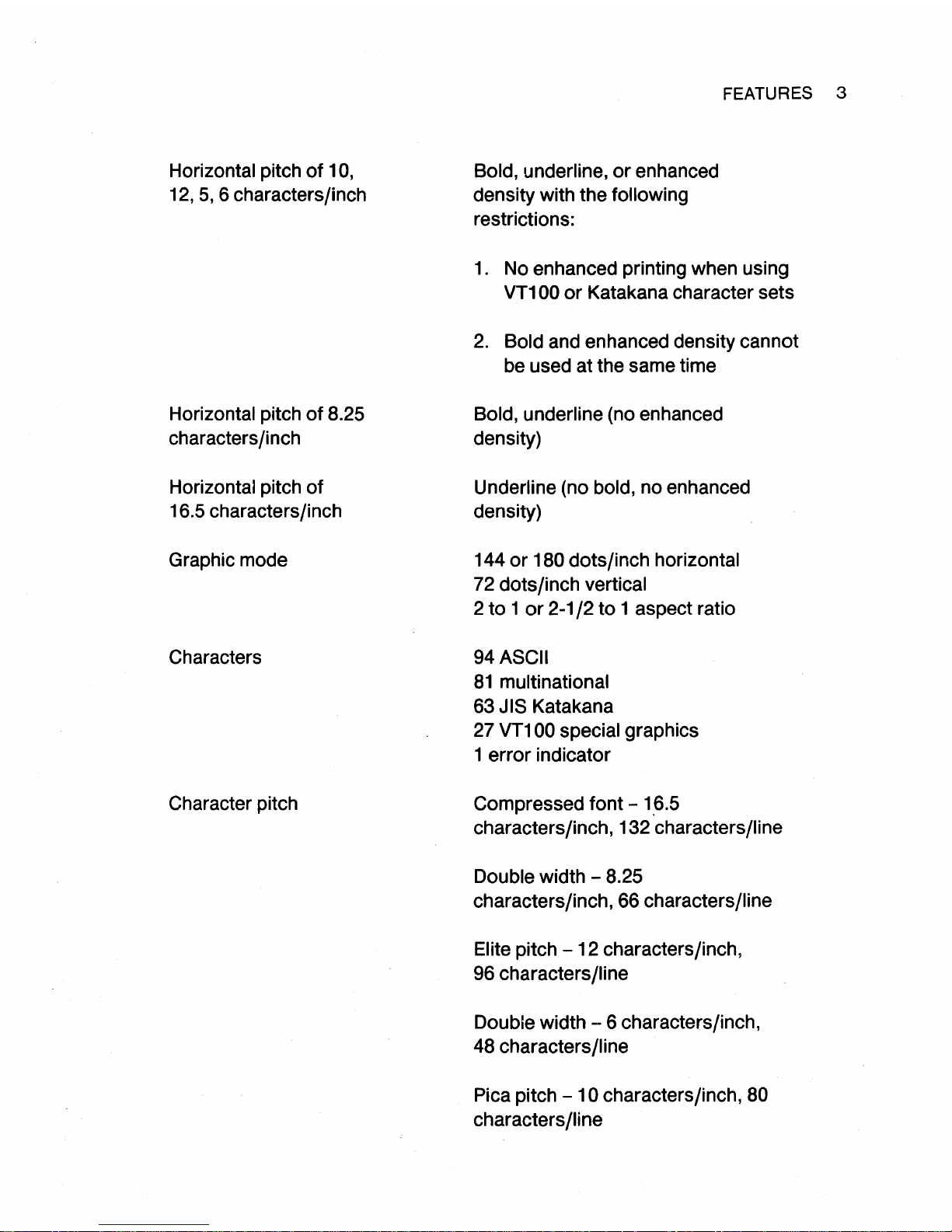
Horizontal pitch
of
10,
12,
5,
6 characters/inch
Horizontal pitch
of
8.25
characters/inch
Horizontal pitch
of
16.5 characters/inch
Graphic mode
Characters
Character pitch
Bold, underline,
or
enhanced
density with the
following
restrictions:
FEATURES 3
1.
No enhanced printing when using
VT100
or
Katakana character sets
2.
Bold and enhanced density cannot
be used at the same time
Bold, underline (no enhanced
density)
Underline (no bold, no enhanced
density)
144
or
180 dots/inch horizontal
72 dots/inch vertical
2
to 1 or
2-1
/2
to
1 aspect ratio
94
ASCII
81
multinational
63 JIS Katakana
27
VT1
00 special graphics
1
error
indicator
Compressed font -
1.6.5
characters/inch, 132 characters/line
Double
width - 8.25
characters/inch, 66
characters/line
Elite
pitch
-12
characters/inch,
96
characters/line
Double width --6 characters/inch,
48
characters/line
Pica pitch
-10
characters/inch, 80
characters/line
4 FEATURES
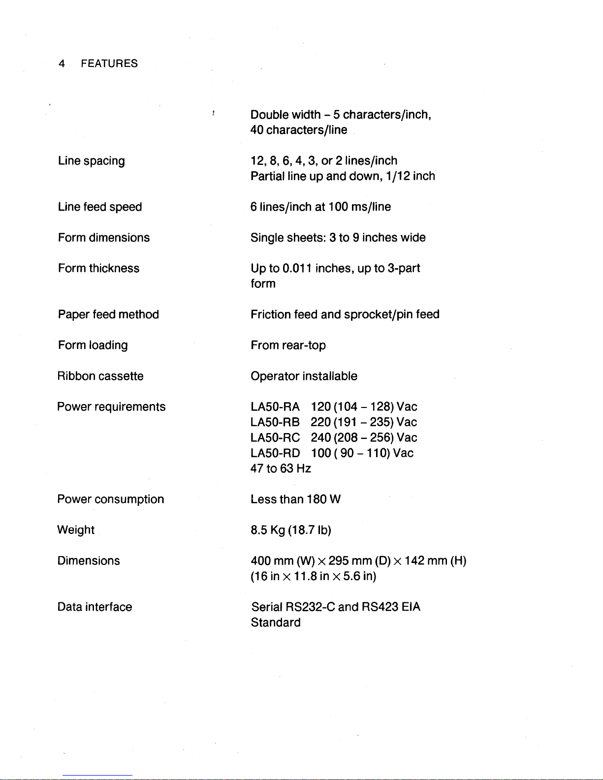
Line spacing
Line feed speed
Form dimensions
Form thickness
Paper feed method
Form
loading
Ribbon cassette
Power requirements
Power consumption
Weight
Dimensions
Data interface
Double width - S characters/inch,
40 characters/line
12,
8,
6,
4,
3,
or
2 lines/inch
Partial line
up and down, 1
/12
inch
6
lines/inch at 100 ms/line
Single
sheets: 3
to
9 inches wide
Up to 0.011 inches, up
to
3-part
form
Friction feed and sprocket/pin feed
From rear-top
Operator
installable
LASO-RA 120 (104
- 128) Vac
LASO-RB 220
(191
- 23S) Vac
LASO-RC
240 (208 - 2S6) Vac
LASO-RD
100 ( 90 - 110) Vac
47
to
63 Hz
Less than
180 W
8.S
Kg (18.7 lb)
400
mm
(W)
x 29S mm
(D)
x 142
mm
(H)
(16 in x 11.8 in x 5.6 in)
Serial RS232-C and RS423 EIA
Standard
COMMUNICATION
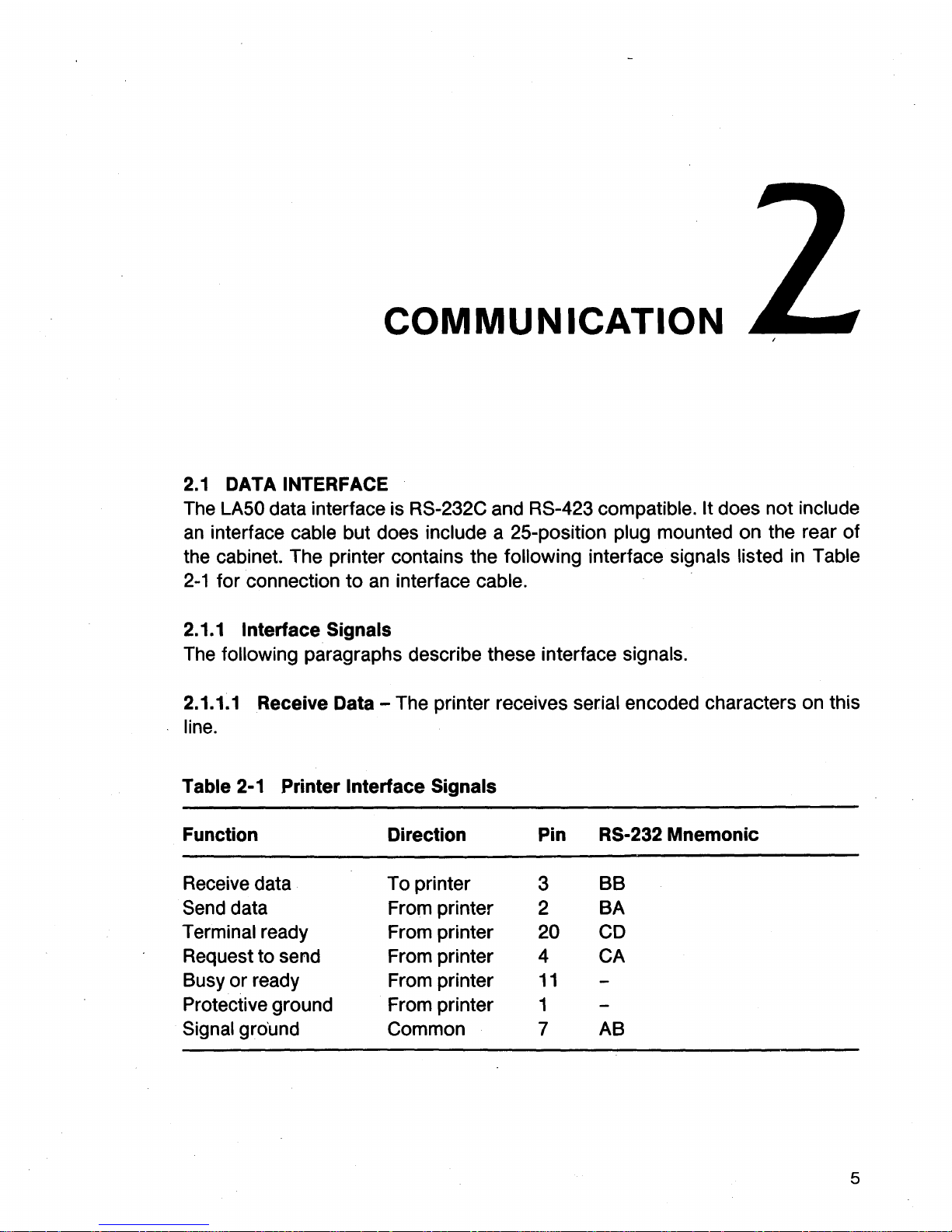
2.1
DATA INTERFACE
The
LASO
data interface is RS-232C and RS-423 compatible. It does not include
an
interface cable but does include a 25-position plug mounted on the rear of
the cabinet. The printer contains the
following interface signals listed
in
Table
2-1
for connection
to
an
interface cable.
2.1.1
Interface Signals
The following paragraphs describe these interface signals.
2.1.1.1 Receive Data - The printer receives serial encoded characters on this
line.
Table 2-1 Printer Interface Signals
Function
Direction
Pin RS-232 Mnemonic
Receive data
To printer
3
BB
Send data From printer
2
BA
Terminal ready From printer 20
CD
Request to send From printer 4 CA
Busy or ready From printer
11
Protective ground From printer 1
Signal gro'und
Common
7
AB
5
6 COMMUNICATION
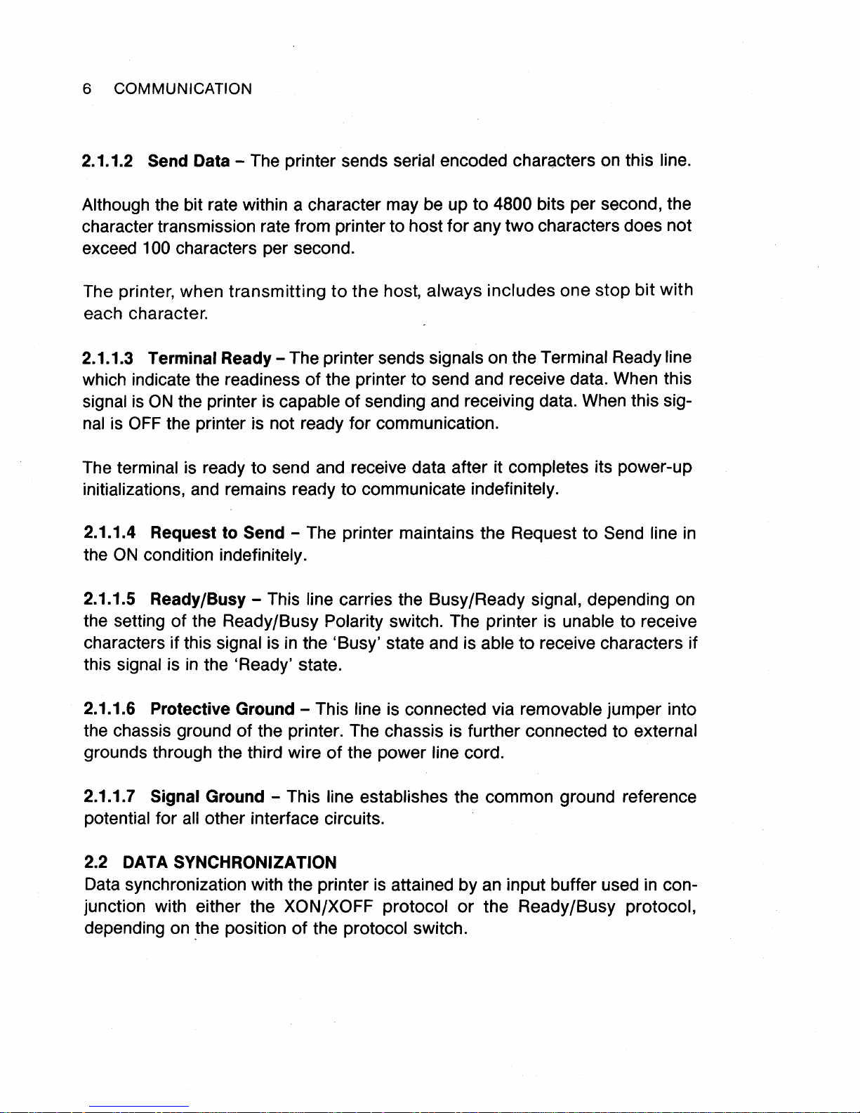
2.1.1.2 Send Data - The printer sends serial encoded characters on this line.
Although
the bit rate within a character may be up
character transmission rate from printer to
exceed 1
The printer,
00 characters per second.
when
transmitting
to
the
host,
host
always
for
to
4800 bits per second, the
any
two
characters does not
includes
one
stop
bit
with
each character.
2.1.1.3
which indicate the readiness
signal is
nal is OFF the printer is not ready
The
initializations, and remains
2.1.1.4 Request
the
Terminal
ON
the printer is capable
Ready-The
terminal is ready
to
ON
condition indefinitely.
printer sends signals on the Terminal Ready line
of
the printer to send and receive data. When this
of
sending and receiving data. When this sig-
for
communication.
to
send and receive data after it completes its power-up
ready
Send - The printer maintains the Request
to
communicate indefinitely.
to
Send line in
2.1.1.5 Ready/Busy - This line carries the Busy/Ready signal, depending on
of
the setting
characters
signal is in the 'Ready' state.
this
the Ready/Busy Polarity switch. The printer is unable to receive
if
this signal is in the 'Busy' state and is able
to
receive characters if
2.1.1.6 Protective Ground - This
of
the chassis ground
the printer. The chassis is further connected to external
grounds through the third wire
2.1.1.7
Signal Ground - This line establishes the common ground reference
potential for all other interface circuits.
2.2 DATA
SYNCHRONIZATION
Data synchronization with the printer is attained
junction with either the
depending on
~he
position
XON/XOFF
line is connected via removable jumper into
of
the
power
protocol
of
the protocol switch.
line cord.
by
an input buffer used in con-
or
the
Ready/Busy
protocol,

COMMUNICATION 7
2.2.1
Input Buffer
All characters received, except nulls and deletes, are temporarily stored
in
an
input buffer before further processing. Nulls and deletes are ignored and do not
occupy space
in
the input buffer. The input buffer has a 2047 character
capacity.
If the printer falls too far behind the incoming data, the input buffer overflows
and
data is lost. If characters are lost due to input buffer overflow, a single sub-
stitute control character (octal 032) is placed
in
the input buffer at the point of
loss. If a character is received with a parity error, the character is replaced
in
the
input buffer by the substitute control character (octal 032) thus causing the error
character (reverse question mark) to be printed. The 032 control character, thus
indicates loss
of
characters, or a character received with parity error.
When the printer is capable of printing, characters are fetched from the input
buffer
and
printed
or
otherwise processed
as
required. When the printer is
incapable
of
printing, the printer scans the input buffer for printer status request
control sequences even if the input buffer is full.
2.2.2 XON/XOFF Protocol
Using the XON/XOFF protocol, the data source becomes synchronized with the
printer
as
described below.
After successfully powering up and becoming enabled to send, the printer
sends
an
XON
control character and constantly monitors the number
of
empty
character positions
in
the input buffer. When the number is less than 128, the
printer sends
an
XOFF
control character, signaling the data source to temporar-
ily stop sending data. Meanwhile, the printer continues
to
take characters from
the input buffer and print or otherwise process them. When the number
of
empty positions
in
the buffer exceeds 224, the printer sends
an
XON
control
character, thus signaling that transmission may resume.
The printer also sends
an
XOFF control character when it is not ready due to
error conditions
or
operator actions. Running out
of
paper
or
detecting a print-
head position failure causes
an
XOFF control character
to
be
sent. The operator
actions of opening the cover
or
placing the printer off-line also cause
an
XOFF
control character to
be
sent.
8 COMMUNICATION
The printer sends
an
XON
control character whenever
an
XOFF state is pres-
ent, and all
of
the following conditions are true.
•
The
printer is ready.
• All fault conditions are cleared.
• There are more than 224 empty positions for characters in the input buffer.
NOTE:
At
power
up,
an XOFF state is assumed.
The printer sends
an
XOFF control character whenever
an
XON
state is pres-
ent, and any
of
the following conditions is true.
• The printer is not ready.
• A fault condition occurs.
• There are less than 128 empty positions for characters
in
the input buffer.
The printer sends
an
extra XOFF control character if more than 64 characters
have been received since the first XOFF control character has been sent.
2.2.3 Ready /Busy Protocol
The
Ready/Busy protocol is functionally the same as the XON/XOFF protocol.
However, instead
of
sending
an
XOFF control character, the printer places the
Ready/Busy signal
in
the Busy state, and instead
of
sending
an
XON
control
character, the printer places the Ready/Busy signal
in
the Ready state.
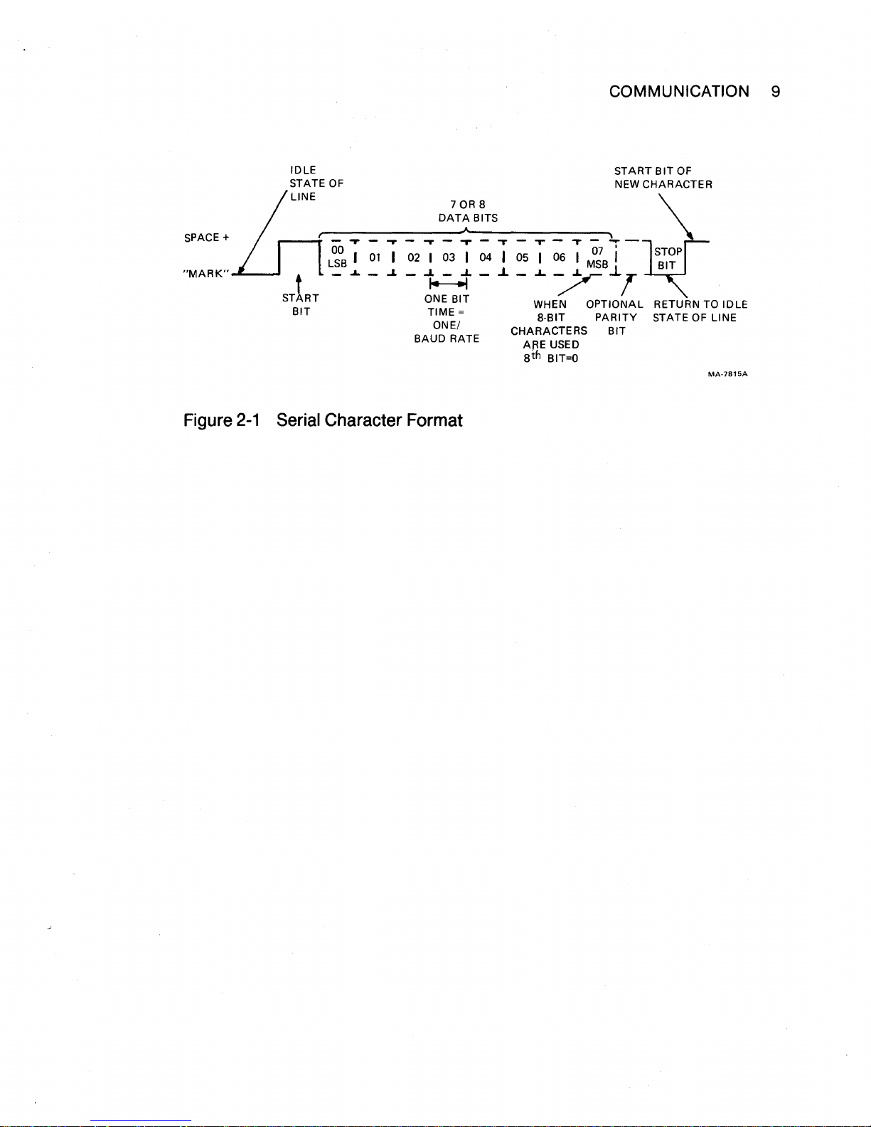
2.3 DATA TRANSMISSION
The
LASO
printer communicates using serial characters. The serial character
format used must
be
the same character format used by the computer. Serial
characters are transmitted using a start bit, 7 or 8 data bits,
an
optional parity bit
and 1 or more stop bits (Figure
2-1
).
The number
of
bits and the polarity
of
the
parity (even or old) is switch selectable. Parity errors can
be
detected for either
polarity.
COMMUNICATION 9
IDLE
START
BIT
OF
STATE OF
NEW CHARACTER
70R8
\
DATA
BITS
-r
T -
_.
-
SPACE+
-
.,. -....
- .... -
,.
"T
07 I
m[TOP
L~OB
I
01
I 02 I 03 I 04 I 05 I 06 I
MSB
I
BIT
"MARK"
t -
.L
- .J. -
~
- .J. - ..L / ..l T
START
ONE BIT WHEN OPTIONAL RETURN TO IDLE
BIT
TIME=
8-BIT
PARITY
STATE
OF
LINE
ONE/ CHARACTERS BIT
BAUD
RATE ARE USED
ath
BIT=O
MA-7815A
Figure
2-1
Serial Character Format

PRINTER
3.1
GENERAL
This chapter describes the
the printer under the access cover. There are
switches in each pack. The switches are used
• National character sets
• Graphics aspect ratio
• XON/XOFF and
•
Right margin
• Baud rate
• Data format.
CONFIGURATION
LASO
ROY
/BUSY protocol
configuration switches located in the front
\
two
switch packs with eight slide
to
configure the:
of
Additional
chapters.
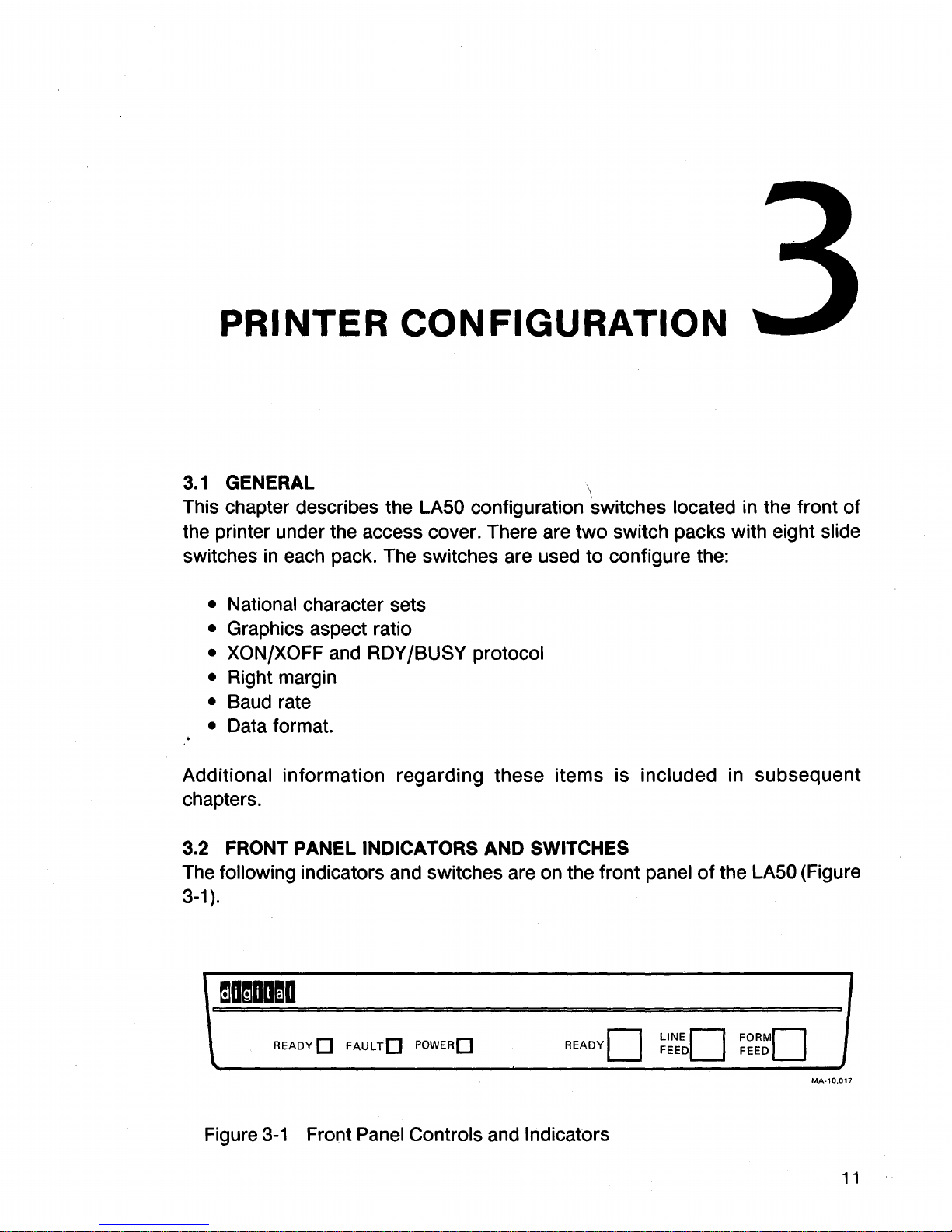
3.2 FRONT PANEL
The following indicators and switches are on the
3-1).
1
mamaoma
information
READY D
\.
Figure
3-1
Front Panel Controls and Indicators
regarding
INDICATORS AND SWITCHES
FAUL
TD
POWERD
these
items
is
front
included
panel
of
in
subsequent
the
LASO
(Figure
J
MA-10,017
11
12 PRINTER CONFIGURATION
3.2. 1 READY Indicator
The
green
READY
light indicates the operating state
of
the printer. The light
·is
on
when the printer is ready to print or is printing. The light is off when the print-
er
is
not ready
and
will not start.
3.2.2 FAULT Indicator
The
red
FAULT light blinks when the printer detects
an
electronic fault. It stays
on
when the printer is out of paper.
3.2.3
POWER
Indicator
The
green
POWER
light is on when power is applied to the printer.
3.2.4 READY Switch
The
READY
switch controls the operating state of the printer. Pressing the
switch
alternately puts the printer
in
the Ready or Not Ready state. Observe the
READY
light to determine the state of operation.
3.2.5
LINE
FEED
Switch
Pressing the LINE FEED switch advances the paper one line.
3.2.6
FORM
FEED
Switch
Pressing the FORM FEED switch advances the paper one full sheet.
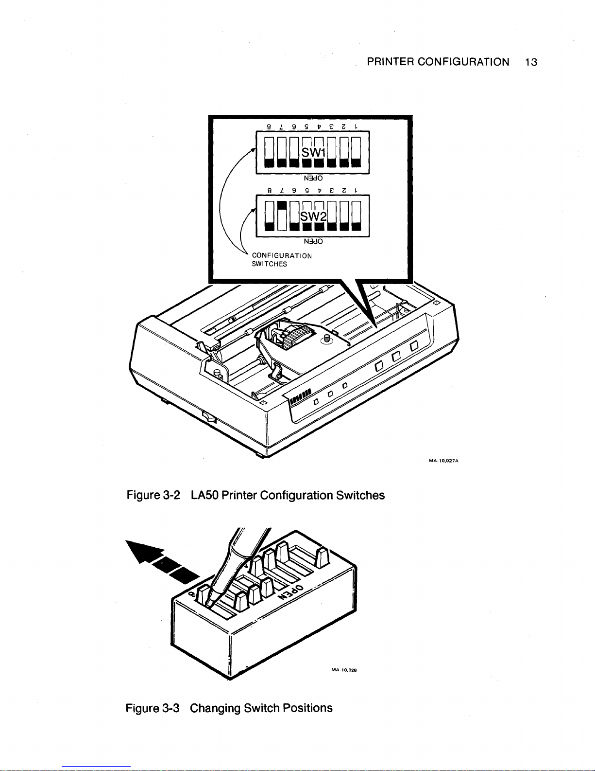
3.3 CONFIGURATION SWITCHES
The
configuration switches are set for printer use with DIGIT AL systems. They
are
located under the access cover (Figure 3-2).
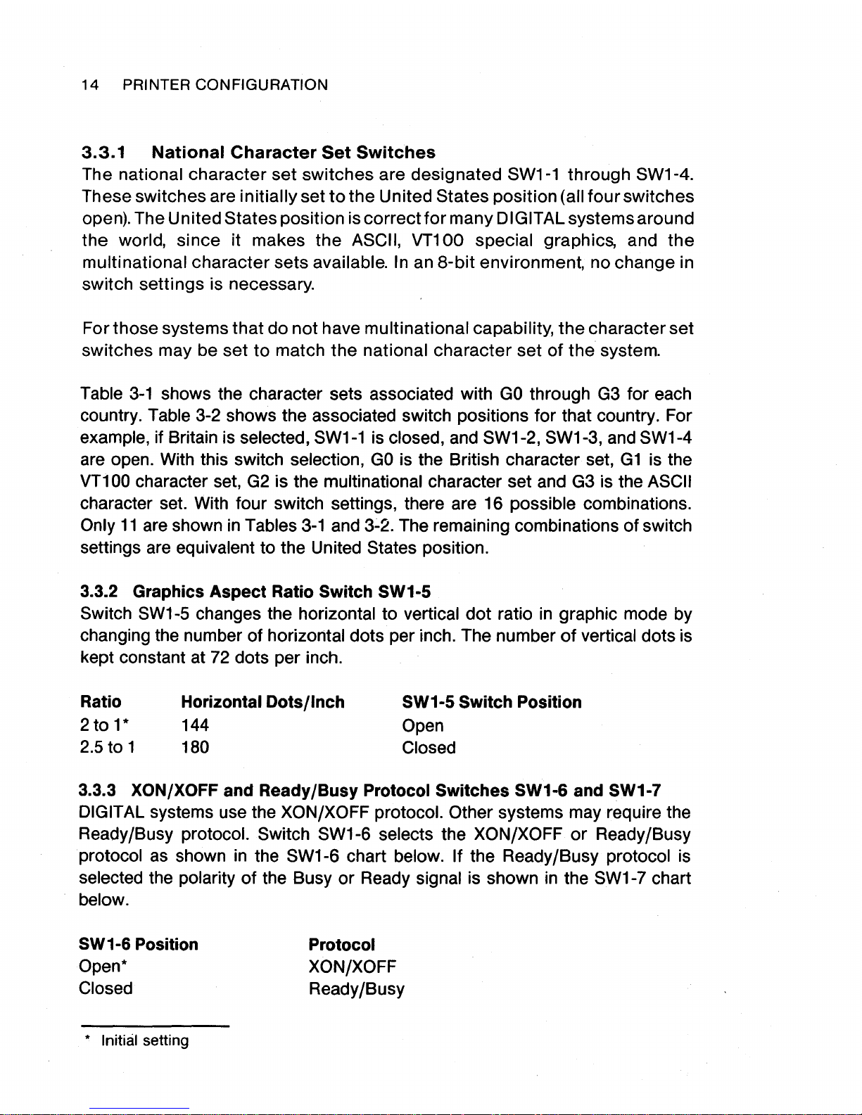
The switch positions
can
be
changed
by
sliding the tab with a ballpoint pen or
equivalent (Figure
3-3).
The rest
of
this chapter describes the switch positions for the system
configurations.
PRINTER CO
NFIGURATION
13
Figure 3-2
LASO
Printer C .
onf1guration Switches
witch Positions Figure 3-3 Changing S .
"""·~"
14
PRINTER CONFIGURATION
3.3.1
National
Character
Set
Switches
The national character
set
switches are des·ignated SW1-1 through SW1-4.
These switches are initially set
to
the
United States position (all
four
switches
open). The United States position is
correct
for
many DIG IT AL systems around
the world, since it makes the ASCII, VT100 special graphics, and
the
multinational character sets available.
In
an
8-bit
environment, no change in
switch settings is necessary.
For those systems that
do
not
have multinational capability,
the
character set
switches may be
set
to
match
the
national character set
of
the system.
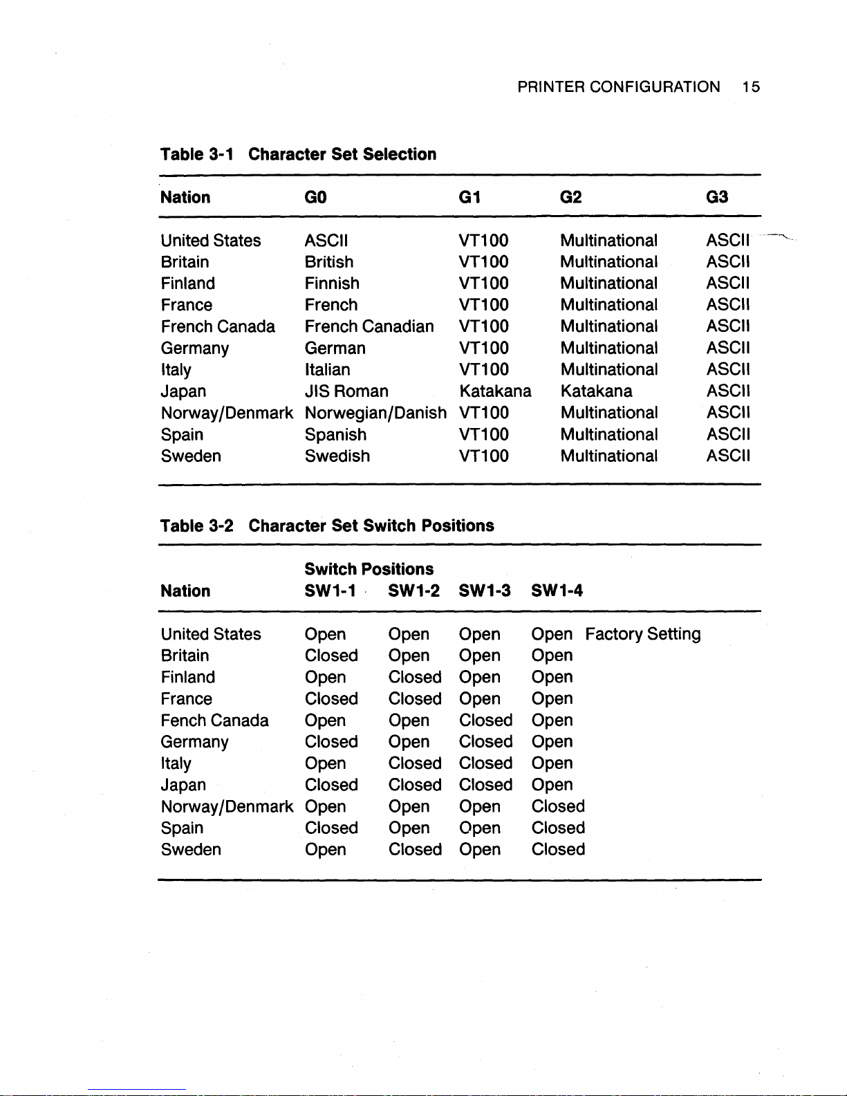
Table
3-1
shows the character sets associated with
GO
through
G3
for each
country. Table 3-2 shows the associated switch positions for that country. For
example, if Britain is selected,
SW1-1
is closed, and SW1-2, SW1-3, and SW1-4
are open. With this switch selection,
GO
is the British character set,
G1
is the
VT100 character set,
G2
is the multinational character set and
G3
is the ASCII
character set. With four switch settings, there are 16 possible combinations.
Only
11
are shown
in
Tables
3-1
and
3.:.2.
The remaining combinations
of
switch
settings are equivalent to the United States position.
3.3.2 Graphics
Aspect
Ratio Switch SW1-5
Switch
SW1
-5
changes the horizontal to vertical
dot
ratio
in
graphic mode by
changing the number of horizontal dots per inch. The number
of
vertical dots is
kept constant at
72
dots per inch.
Ratio
2to1*
2.5to1
Horizontal Dots/Inch
144
SW1-5 Switch Position
Open
180
Closed
3.3.3 XON/XOFF and Ready/Busy Protocol Switches SW1-6 and SW1-7
DIGIT AL systems use the XON/XOFF protocol. Other systems may require the
Ready/Busy protocol. Switch SW1-6 selects the XON/XOFF
or
Ready/Busy
protocol
as
shown
in
the SW1-6 chart below. If the Ready/Busy protocol is
selected the polarity
of
the Busy
or
Ready signal is shown
in
the
SW1
-7 chart
below.
SW1-6 Position
Open*
Closed
* Initial setting
Protocol
XON/XOFF
Ready/Busy
PRINTER CONFIGURATION
15
Table 3-1
Character Set
Selection
Nation
GO
G1
G2 G3
United States ASCII
VT100
Multinational ASCII
..
----...
__
Britain
British
VT100
Multinational ASCII
Finland
Finnish
VT100
Multinational ASCII
France
French
VT100
Multinational
ASCII
French Canada French Canadian
VT100
Multinational
ASCII
Germany German
VT100
Multinational ASCII
Italy Italian
VT100
Multinational ASCII
Japan JIS Roman Katakana Katakana
ASCII
Norway /Denmark
Norwegian/Danish
VT100
Multinational
ASCII
Spain
Spanish
VT100
Multinational ASCII
Sweden
Swedish
VT100
Multinational
ASCII
Table 3-2
Character Set Switch Positions
Switch Positions
Nation
SW1-1
·
SW1-2 SW1-3 SW1-4
United States Open Open
Open
Open
Factory Setting
Britain Closed
Open
Open Open
Finland Open Closed Open Open
France Closed Closed
Open Open
Fench Canada Open Open
Closed Open
Germany Closed
Open
Closed Open
Italy Open Closed Closed
Open
Japan Closed Closed Closed
Open
Norway /Denmark Open Open
Open Closed
Spain Closed Open Open Closed
Sweden Open Closed Open Closed
16
PRINTER CONFIGURATION
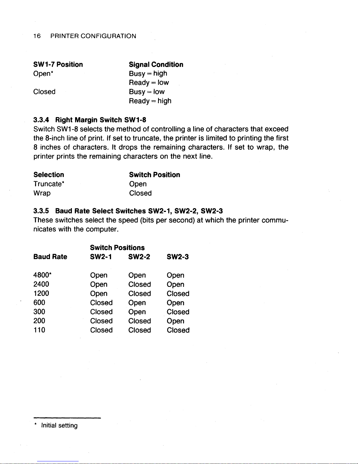
SW1-7 Position
Open*
Closed
Signal Condition
Busy=
high
Ready=low
Busy=low
Ready=high
3.3.4 Right Margin Switch SW1-8
Switch
SW1
-8
selects the method
of
controlling a line
of
characters that exceed
the 8-inch line
of
print. If set to truncate, the printer is limited to printing the first
8 inches
of
characters. It drops the remaining characters. If set to wrap, the
printer prints the remaining characters on the next line.
Selection
Truncate*
Wrap
Switch Position
Open
Closed
3.3.5 Baud Rate Select Switches SW2-1, SW2-2, SW2-3
These switches select the speed (bits per second) at which the printer communicates with the computer.
Switch Positions
Baud Rate
SW2-1
SW2-2 SW2-3
4800*
Open Open
Open
2400
Open Closed
Open
1200
Open
Closed Closed
600
Closed Open
Open
300 Closed Open
Closed
200
Closed
Closed Open
110
Closed Closed
Closed
* Initial setting
 Loading...