

Page 1
EK-OLASO-UG-001
.
Installing
and. Using
the
LASO
Printer
mamaama
.
Page 2

Page 3

EK-0
LASO-UG-001
Installing
and
Using
the
LASO
Printer
Prepared
by
Educational
Services
of
Digital
Equipment
Corporation
Page 4
1st
Edition, August
1982
Copyright©
1982
by Digital Equipment Corporation
All Rights Reserved
The reproduction of this
material, in part
or
whole, is strictly prohibited. For
copy information, contact the
Educational Services Department, Digital
Equipment Corporation, Maynard, Massachusetts
01754.
The information in this document is subject
to
change without notice. Digital
Equipment Corporation assumes no responsibility for any errors that may
appear in this document.
Notice: This equipment generates and uses radio frequency energy.
It
has
been type tested and found
to
comply with
the
limits for a Class B computing
device in accordance with the specifications in
Subpart J
of
Part
15
of FCC
Rules,
which are designed
to
provide reasonable protection against radio and
television interference in a residential installation. However, there is no
guarantee that interference
will not occur in a particular installation. If this
equipment does cause interference to radio or
television reception, the user is
encouraged
to
try
to
correct the interference.
Printed in Japan.
The
following are trademarks of Digital Equipment Corporation, Maynard,
Massachusetts.
DEC
DEC
US
DIGITAL
Digital
Logo
PDP
UNIBUS
VAX
OS/8
DECnet
DECsystem-1
O
DECSYSTEM-20
DECwriter
DIBOL
EduSystem
OMNIBUS
IAS
MASS BUS
PDT
RSTS
RSX
VMS
VT
Page 5
---------------------------iii
CONTENTS
Introduction
Installing Printer . . . . . . . . . . . . . . . . . . . . . . . . . . . . . . . . . . . . . . . . . . . . . . . . . . . . . . . 1
Packing
Removal . . . . . . . . . . . . . . . . . . . . . . . . . . . . . . . . . . . . . . . . . . . . . . . . . 1
Installing Ribbon
Cartridge........................................
2
Installing Power Cable . . . . . . . . . . . . . . . . . . . . . . . . . . . . . . . . . . . . . . . . . . . . 4
Inserting Paper . . . . . . . . . . . . . . . . . . . . . . . . . . . . . . . . . . . . . . . . . . . . . . . . . . . . . . . . 5
Inserting Pinfeed Paper . . . . . . . . . . . . . . . . . . . . . . . . . . . . . . . . . . . . . . . . . . . 5
Inserting Single Sheet Paper
.....................................
1 O
Self-Test Procedure
....................................................
12
Installing System Cable
................................................
14
Front Panel Indicators and Switches . . . . . . . . . . . . . . . . . . . . . . . . . . . . . . . . . . . 1 5
Printer
Controls . . . . . . . . . . . . . . . . . . . . . . . . . . . . . . . . . . . . . . . . . . . . . . . . . . . . . . . . 16
Maintaining Printer . . . . . . . . . . . . . . . . . . . . . . . . . . . . . . . . . . . . . . . . . . . . . . . . . . . . . 17
Troubleshooting Printer
.. ..
. . .
..
.. . ..
. . .
..
.. . .. . ..
. .
.. ..
. .
.. . ..
. .
..
. . . .
18
Operator Checklist . . . . . . . . . . . . . . . . . . . . . . . . . . . . . . . . . . . . . . . . . . . . . . . . 1 8
Replacing Printhead
..............................................
20
Replacing
Fuse
...................................................
24
Printer Configuration
...................................................
26
Configuration Switches
...........................................
26
National Character Set Switches
..
. . . . .
..
. .
..
. .
.. .. ..
.. . .. . ..
. . . . . 28
Graphics Aspect Ratio Switch
.....................................
29
XON/XOFF and Ready/Busy Protocol Switches
...................
29
Right Margin Switch
..............................................
30
Baud Rate Select Switches . . . . . . . . . . . . . . . . . . . . . . . . . . . . . . . . . . . . . . .
30
Data Format Switches . .
.. . ..
. . . . . . .
.. . ..
. . .
.. . .. . .. . ..
. . . . . .
..
.. . 31
Specifications . . . . . . . . . . . . . . . . . . . . . . . . . . . . . . . . . . . . . . . . . . . . . . . . . . . . . . . . . .
32
Field Service Information .
.. . ..
..
. . . .
..
. .
.. . .. ..
. . .
.. . ..
..
. .
..
. . . .
..
. .
..
34
Page 6
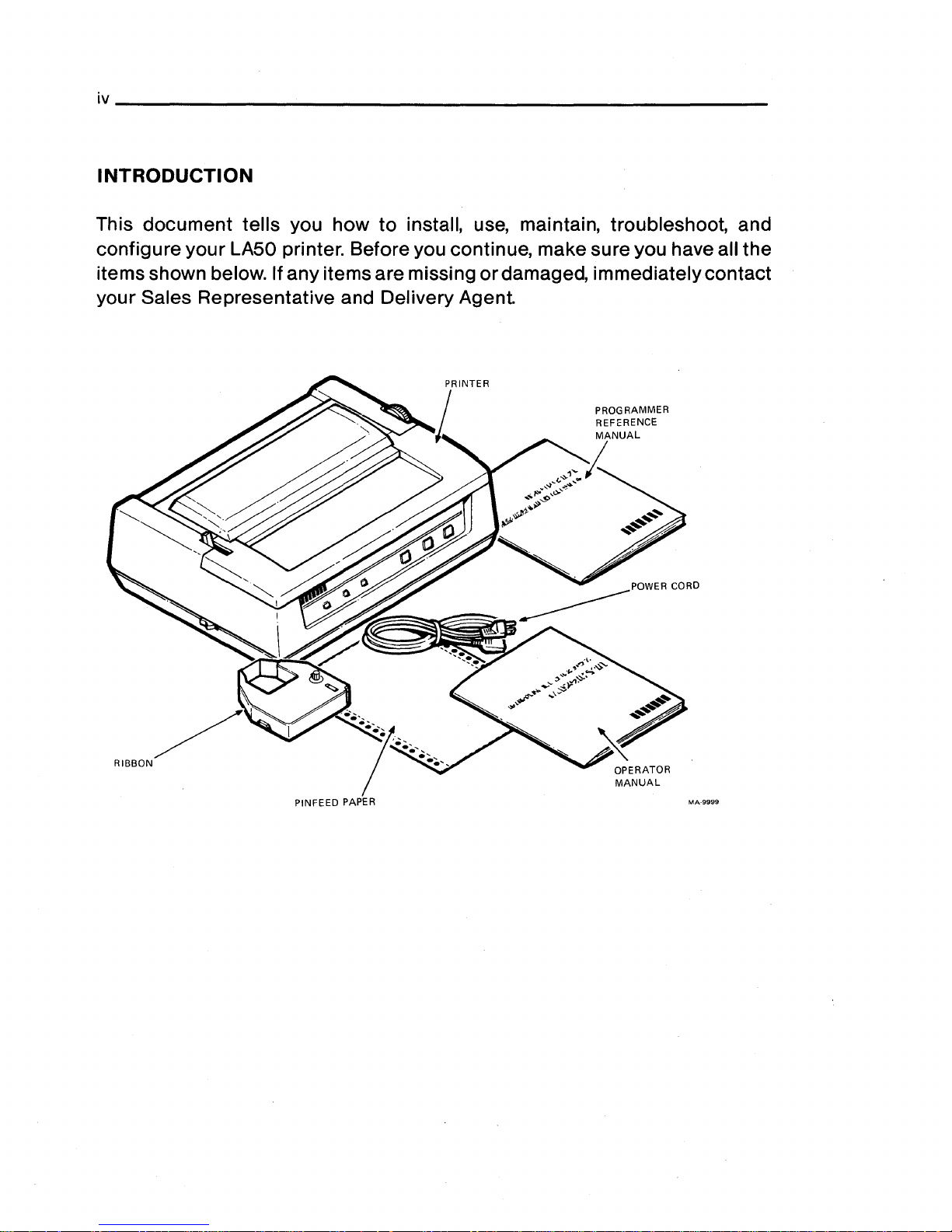
INTRODUCTION
This
document
tells you how
to
install, use, maintain, troubleshoot, and
configure
your
LA50 printer. Before you continue, make sure you have all the
items shown below. If any items are missing
or
damaged, immediately contact
your Sales Representative and Delivery Agent.
OPERATOR
MANUAL
Page 7
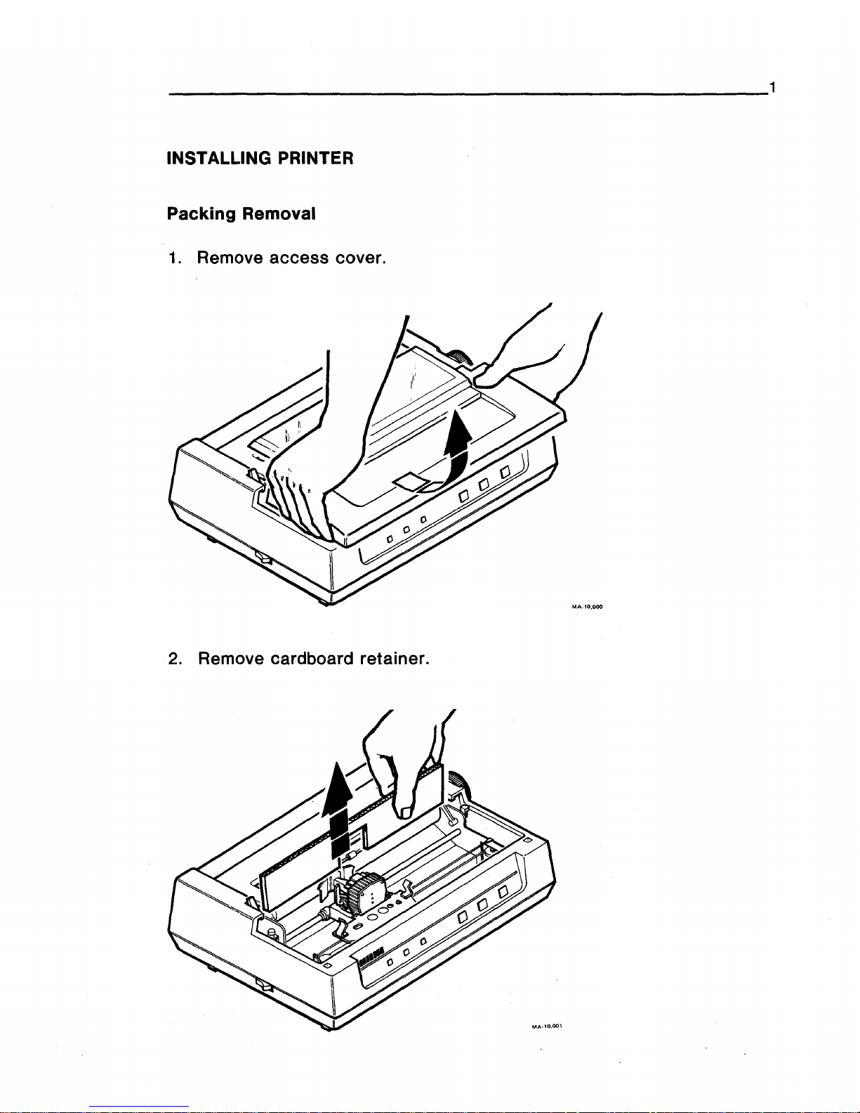
INSTALLING PRINTER
Packing
Removal
1.
Remove
access
cover.
2. Remove c d
ar board ret .
a mer.
Page 8
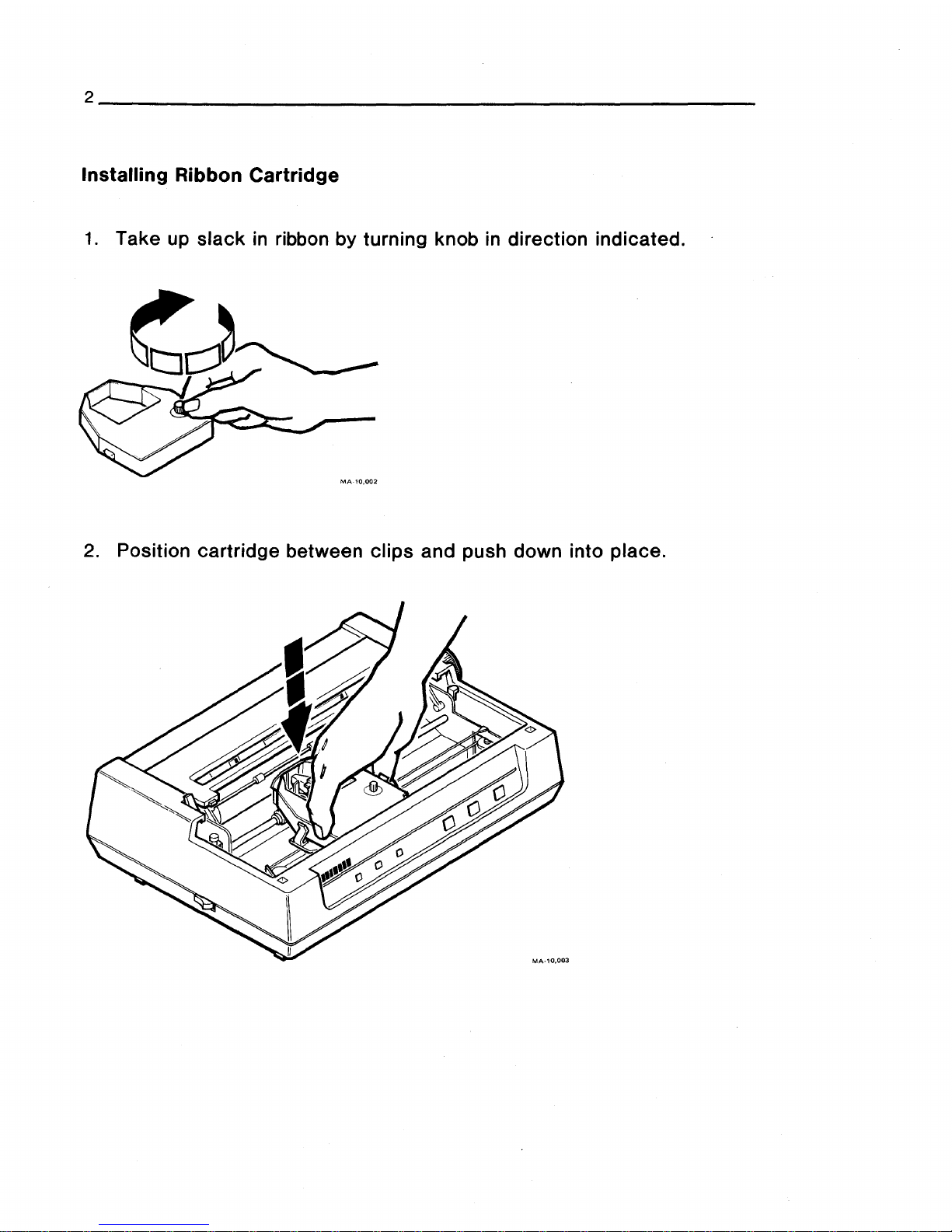
Installing
Ribbon
Cartridge
1.
Take up slack
in
ribbon by turning knob in direction indicated.
2.
Position cartridge between
clips
and push down into place.
Page 9
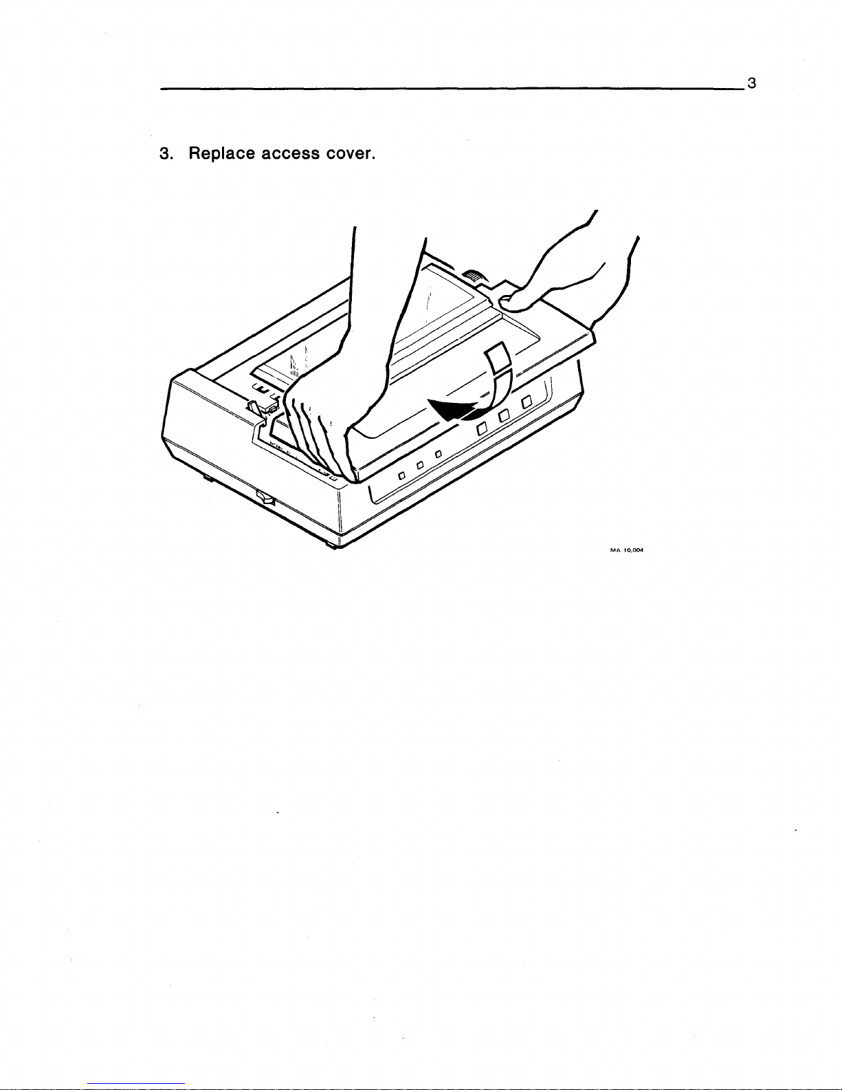
3
3
· Repla
ce access
cover.
Page 10
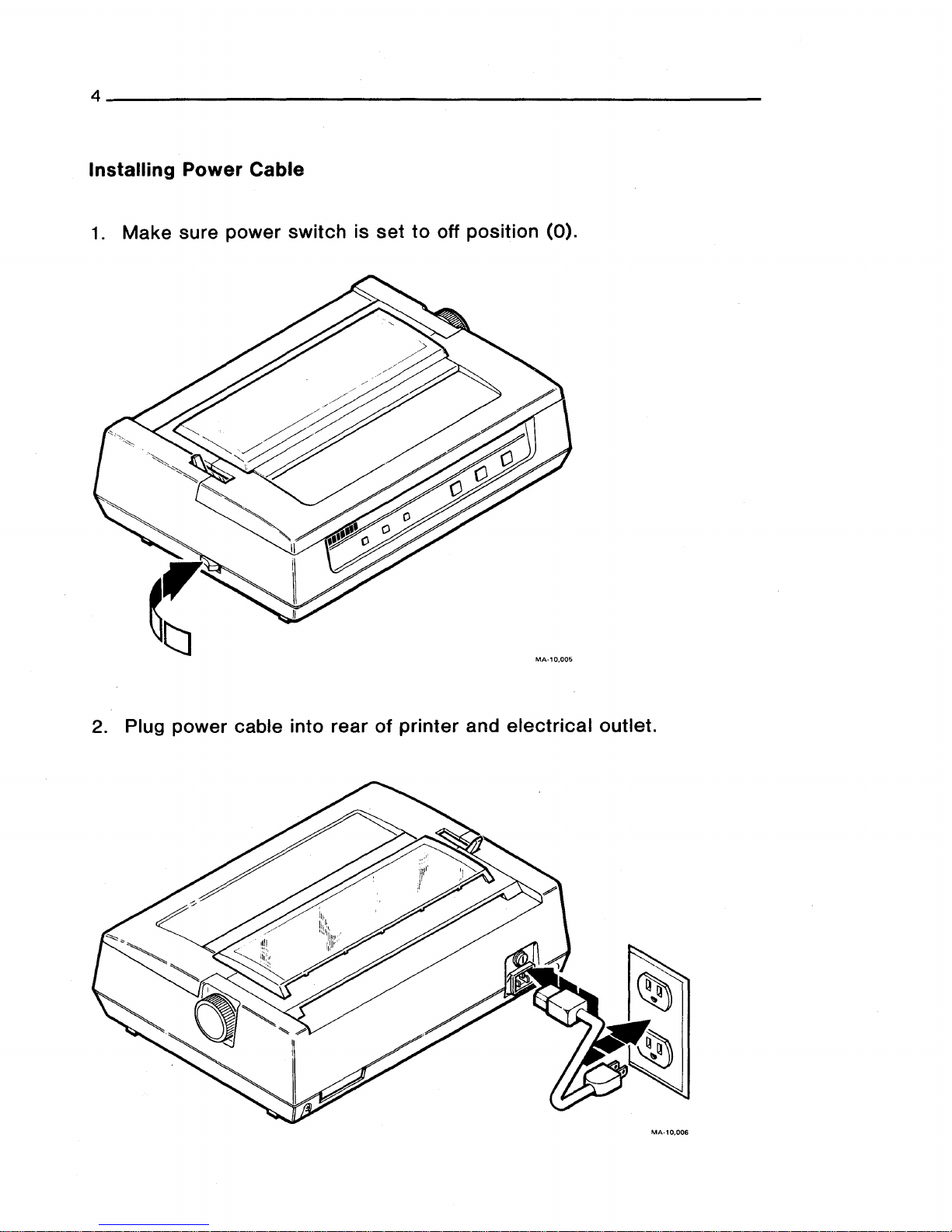
Installing
Power
Cable
1.
Make
sure
power
switch
is
set
to
off
position
(0).
2. Plug
power
cable into
rear
of
printer
and
electrical
outlet.
MA·10,006
Page 11
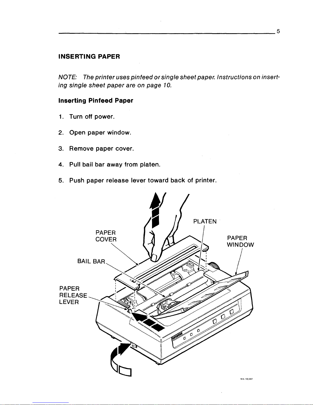
INSERTING
PAPER
NOTE: The
printer
uses
pinfeed
or
single sheet paper. Instructions on insert-
ing single
sheet
paper
are on page
10.
Inserting Pinfeed Paper
1.
Turn off power.
2.
Open
paper
window.
3. Remove
paper
cover.
4. Pull bail bar away from platen.
5. Push
paper
release lever
toward
back
of printer.
MA-10,007
Page 12
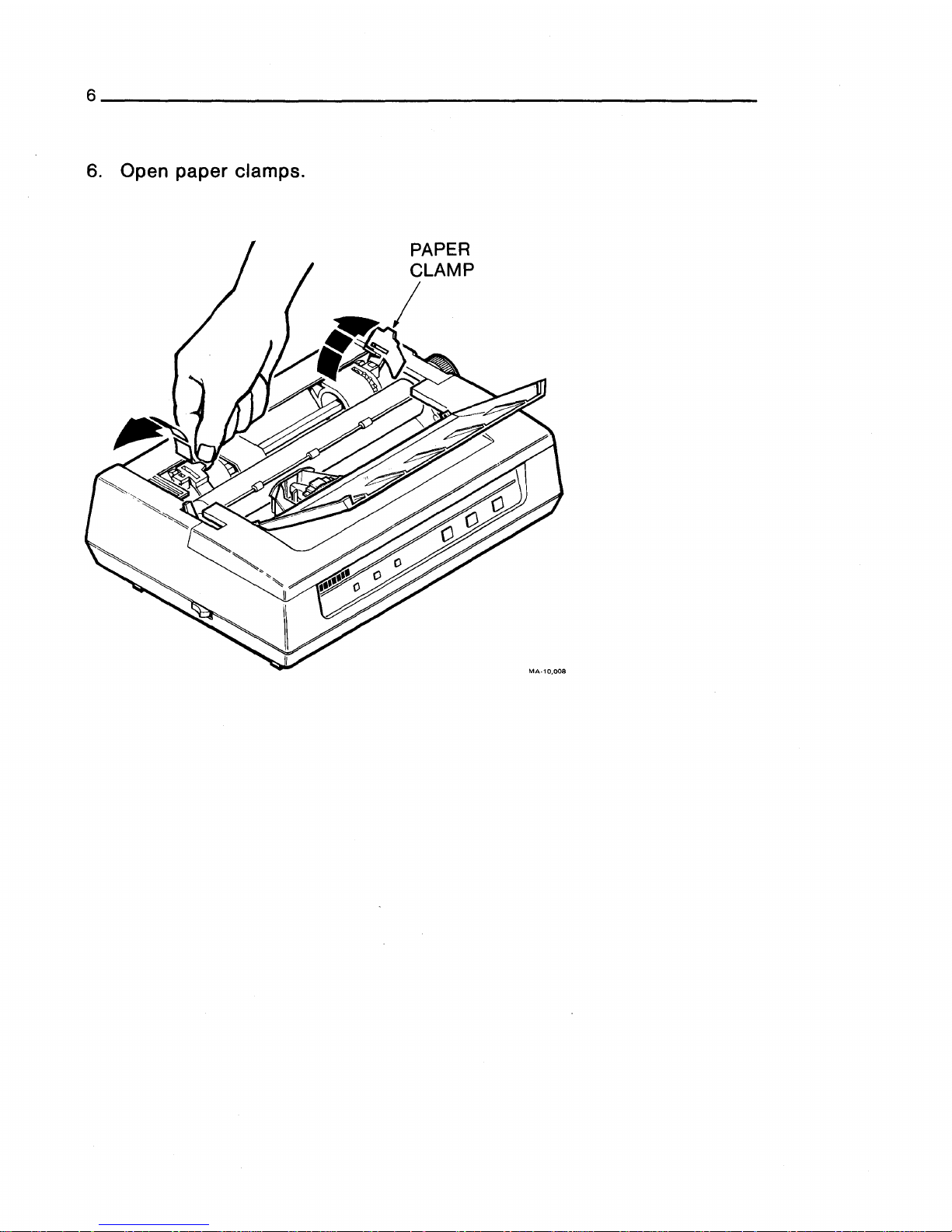
6. Open paper clamps.
Page 13
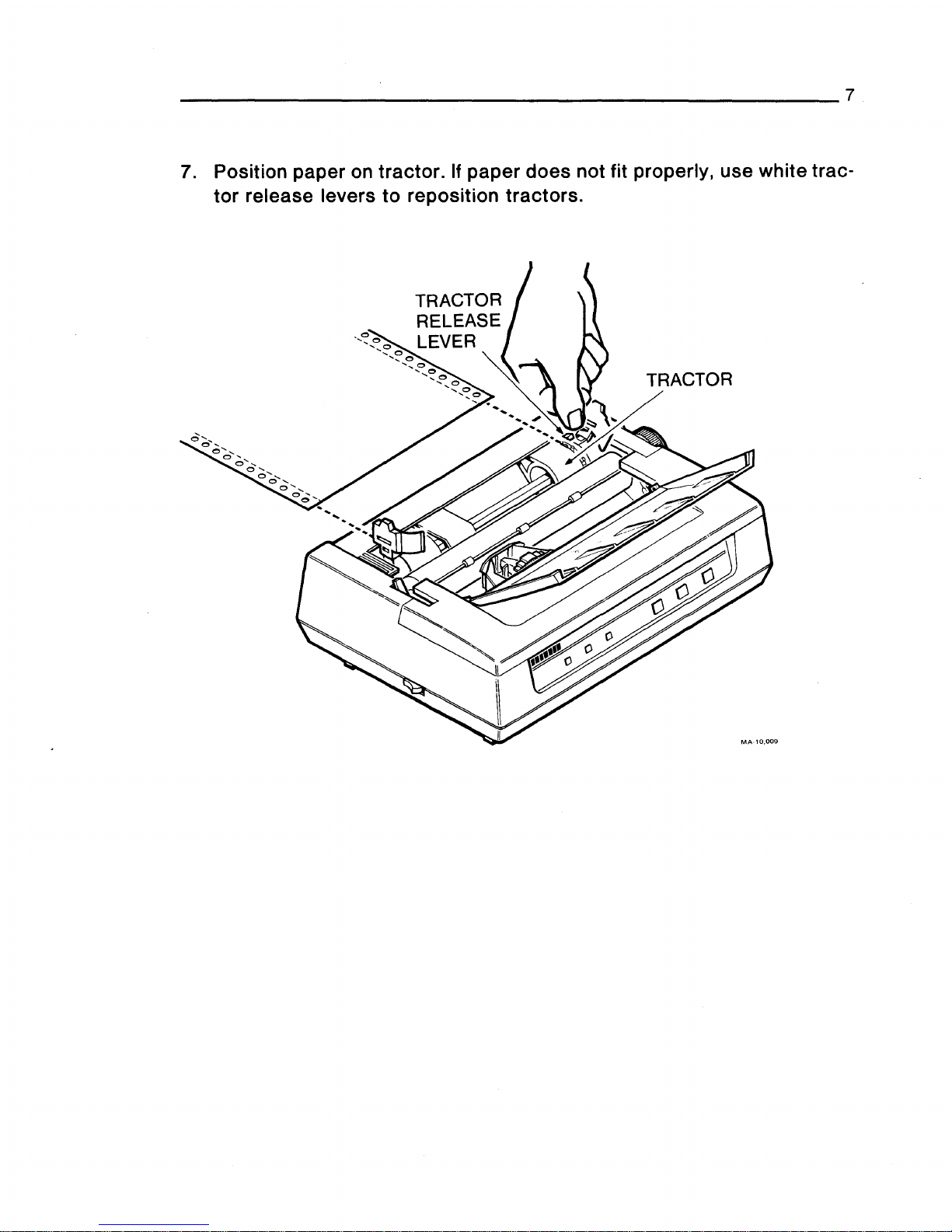
7. Position paper on tractor.
If
paper does not fit properly, use white trac-
tor
release levers
to
reposition tractors.
Page 14

8. Close paper clamps.
9. Turn platen knob and guide
paper
behind platen.
10. Advance paper until
top
of
paper
is
behind bail bar.
BAIL BAR
PLATEN
,KNOB
I
MA·10,010
Page 15

9
11.
Push bail ba .
r
against platen.
12. Close
paper window.
13.
Replace paper cover.
Page 16

Inserting Single Sheet Paper
1.
Turn off power.
2. Open paper window.
3.
Pull bail bar away from platen.
4.
Push
paper
release lever
toward
back
of
printer.
PAPER
WINDOW
\
MA-10,012
Page 17

5. Push
paper
through slot in
paper
cover
and guide it
to
front of platen.
Align paper.
6. Pull
paper
release lever
toward
front of printer.
7. Push bail bar against platen.
8. Close
paper
window.
9. Turn platen knob
to
reposition paper.
SLOT
PLATEN
KNOB
/
Page 18

SELF-TEST PROCEDURE
NOTE: The
cover
must
be
on to run self-test.
1.
Push and hold down FORM FEED button.
2.
Turn the
power
on.
3. Release FORM FEED button.
Page 19

You should get the following printout.
ABCDEFGHI
JKLMNOPQRSTUVWXYZ
[\.J
A_'
abcdefgh
i j K 1
mnopqr·s.tuvwxyz
(:
)~·
!
"tt$X&'
<)
*+,
-
./01
BCDEFGHIJKLMNOPQRSTUVWXYZC\.JA_'abcdefghijKlmnopqrstuvwxyz{:}~
!"tt$X&'<>*+,-./012
CDEFGHI JKLMNOPQRSTUVWXYZ
[\.J
A-'
abcdefgh
i j K 1
mnopqrstuvwxyz
<:
}~·
!
"tt$X&'
( >
*+,
-
./0123
DEFGHI
JKLMNOPQRSTUVWXYZ C\.J
''-'
abcdefgh
i j K 1
mnopqrstuvwxyz
<:
}~
!
"tt$X&'
<)
*+,
-./01234
EFGHI
JKLMNOPQRSTUVWXYZ
[\.J
"_'
abcdefgh i jK 1 mnopqrstuvwxyz
(:
)~
'"
tt$X&'
< >
*+,
-
./012345
FGHI
JKLMNOPQRSTUVWXYZ
['\J
"-'
abcdefgh i jKl
mnopqrstuvwxyz
<:
)~
'"
tt$X&-·
()
*+, -./0123456
GHI
~TKLMNOPQRSTUVWXYZ
[\.J "-'abcdefgh
i
_i
K 1
mnopqrs.tuvwxyz
<:
)~
'"
tt$X&'
<)
*+,
-
./01234567
HIJKLMNOPQRSTUVWXYZC\.l"-'abcdefghijKlmnopqrstuvwxyz{:}~
!"tt$X&'()*+
1
-./012345678
I
JKLMNOPQRSTWWXYZ
['\J
"_'
abtdefgh
i j K 1
mnopqrstuvwxyz
<:
}~·
'"
#$%&·'
()
*+,
-
./0123456789
JKLMNOPQRSTUVWXYZC\.l"-'abcdefghijKlmnopqrstuvwxyz{I}~
!"#$%&'<>*+,-./0123456789:
KLMNOPQRSTUVWXYZ
[\.J
"-'
abcdef
gh
i j K 1
mnopqrstuvwxyz
<:
}~
'"
tt$X&'
<)
*+,
-
./0123456789:;
LMNOPQRSTUVWXYZC\.l"-'abcdefghijKlmnopqrstuvwxyz<:
}~
1
"#$%&'<>*+,-./0123456789:;<
MNOPQRSTWWXYZ
[\.J
"-'
abcdefgh
i j K 1
mnopqrstuvwxyz
{I}~
!
"#$%&'
()
*+, -./0123456789:;
<=
NOPQRSTUVWXYZ
[\.J "-·,
abcdefgh
i j k 1
mnopqrstuvwxyz
<:
}~
'"
#$%&'
<)
*+, -./0123456789:;
<=>
OPQRSTUVWXYZ
[\.J
"-'
abcdefgh
i j K 1
mnopqrstuvwxyz
<I)~·
!
"tt$X&'
<)
*+,
- •
/0123456789:;
<=>?
PQRSTUVWXYZ
[\.]
"-'
abcdefgh
i j K 1
mnopqrstuvwxyz
<:
}~
!
"#$X&'
<)
*+ ,-./0123456789:
; <=>?Gl
MA·l0,016
4. After a few lines print out, turn off power to stop printer.
Followup
If
printer passes self-test, continue to next instruction.
If
printer does not
pass
self-test,
or
FAULT light blinks, refer to Troubleshooting section.
Page 20

INST ALLING SYSTEM CABLE
1.
Plug system cable into
back
of printer, and
tighten
two
retaining
screws by turning them
clockwise.
2. Install other end of cable
as
described in
your
system
installation man-
ual.
~
RETAINING
SCREW
MA-10,015
3. Installation is now complete. Please fill
out
and return
the
enclosed
installation card.
A Customer Identification Number is
located
on
the
rear
of
the top
cover. If
you are capitalizing
this
equipment,
use
this
number in
your
records
as
identification of
the
printer, and
place
your
asset
tag
on
the
top
cover.
Become familiar with
the
information in
the
next
section
before you oper-
ate
the printer with
your
system.
Page 21

FRONT PANEL INDICATORS AND SWITCHES
1111111
READY D FAUL
TD
POWERD
READY
Indicator
The green READY light
indicates
the
printer's
operating state. The light is
on when
the
printer is ready
to
print,
or
is printing. If
the
light is off,
the
printer is not ready and will not start.
FAULT
Indicator
The red FAULT light blinks when the
printer
detects
an
electronic
fault.
The light
stays
on when the printer is out
of
paper.
POWER
Indicator
The green POWER light is on when you
apply
power
to
the
printer.
READY
Switch
The READY switch
controls
the
printer's
operating
state. Pressing
the
switch puts
the
printer
in
either
the
ready
or
not
ready state. Watch
the
READY light
to
determine
the
operating
state.
LINE FEED
Switch
Pressing the LINE FEED
switch
advances
the
paper
one line.
FORM FEED
Switch
Pressing the FORM FEED switch
advances
the
paper
one full sheet.
Page 22

PRINTER CONTROLS
MA-10,018
Paper Bail
The
paper
bail
holds
the
paper
against
the
platen. Red
etch
marks
on
the
bail help you position
paper
on the
platen
and
locate
the horizontal print-
ing position.
Paper Thickness Lever
The
paper
thickness
lever
adjusts
the
printhead
position
to
allow for dif-
ferent printing form thickness. Keep
the
lever
close
to
the
platen
for
nor-
mal printing
..
Move the lever away from
the
platen
for
thicker
sheets
and
multicopy forms.
Paper Release Lever
The
paper
release
lever
controls
paper
holding tension.
In
the
forward po-
sition,
paper
is held
tightly
against
the
platen.
In
the
backward
position,
the paper is free
for
positioning
or
removal.
Platen Knob
The platen knob
allows
manual
control
of
the
platen for
paper
insertion,
and for changing
the
paper's
vertical
position.
Page 23

MAINTAINING PRINTER
The printer does not need preventive maintenance. Clean
its
surfaces
and platen with a damp
cloth
only. Do not use
cleaners
with solvents or
excessive
water.
Office Area
To help maintain proper
operating
temperatures, keep the printer away
from extreme temperature,
such
as
direct
sunlight, room heaters, and air
conditioners.
Keep paper clips, coffee,
matches,
cold drinks, and
other
small objects
and liquids away from
the
printer.
Paper
Select
the right paper for
the
job. Always make sure
to
position
paper
squarely and
set
it
tightly
around the platen. Also make sure
the
paper
thickness
lever is in
correct
position. To remove
paper
from
the
printer,
use the form feed switch,
or
turn
the
platen knob.
Printhead and Ribbon Cartridge
Keep samples of early
printouts
to
help you know when
to
replace
the
printhead and ribbon cartridge. Use only DIGITAL-approved ribbon car-
tridges
in
the printer.
Other
cartridges
may not give
the
same perform-
ance and may damage
your
printer. Store
printheads
and ribbon car-
tridges
in
their
containers, in
the
same environment as
the
printer. (Refer
to
specifications
at the
back
of
this
document.)
Page 24

TROUBLESHOOTING THE PRINTER
Operator
Checklist
Try
to
correct
the trouble
as
listed
below.
CAUTION:
Always
turn
off
the
printer
before
you
attempt
to
correct
a
problem.
If you
cannot
correct
the
trouble:
Turn off the
printer
and
contact
your
dealer
or
the
nearest
DIGITAL
service
technician.
Trouble
Printer does not
start when power
is
turned
on.
No printout. FAULT
light is
on.
Pressing
the READY button
causes printer
to
print one line.
Probable
Cause
Power cord not
connected,
or
broken
Power source
fault
Fuse open
Printer
out
of
paper
No printout. Access cover open
FAULT light is
on.
READY light is out
and pressing the READY
button does not start
printer.
Corrective
Action
Check power cord
connections;
check
power
cord
for
damage.
Check power
at
power
receptacle.
Make sure fuse is in
place. Replace fuse if
blown. Refer
to
Fuse
Replacement.
Reload paper and press
the READY button.
Close cover and press
the READY button.
Page 25

Trouble
Probable Cause
Corrective Action
Light print. Paper thickness
Reset paper thickness
lever set incorrectly
lever
to
a position
closer
to
the
platen.
Ribbon worn
Replace ribbon cartridge.
Carriage moves, but Paper thickness Reset paper thickness
no printout
lever set
incorrectly
lever to a position
closer
to
the platen.
Printhead fault
Replace
the
printhead.
Refer
to
Printhead
Replacement.
Missing dots
in
print; Printhead fault Replace
the
printhead.
always in same row. Refer
to
Printhead
Replacement.
Paper jams. Paper path
obstructed
Clear paper path.
Paper thickness
lever Reset paper thickness
set
incorrectly
lever
to a position away
from
the
platen.
Pinfeed
paper
jams.
Tractors positioned
Release and reposition
incorrectly
for
paper
the
tractors. Avoid
width
pulling
or
compressing
paper.
Page 26

20
Replacing Printhead
1.
Turn off
power.
2. Remove
access
cover.
3. Remove
"bb
n on
cartridge.
Page 27

21
4
·
Push
pr"
mthead ret .
amer
clips away from head.
MA·10,021
5.
Page 28

6.
Plug
in
replacement head.
Make
sure it is fully seated.
7.
Return printhead retainer
clips
to
their
original positions.
Page 29

23
8. Replace
"b
n bon
cart
"d
n ge.
9.
Replace
acces
s cover.
Page 30

Replacing
Fuse
1.
Turn off power.
MA-10,005
2. Unplug
power
cord from
power
outlet.
Page 31

3. Turn fuse retainer
counterclockwise.
FUSE RETAINER
MA-10,026
4.
Remove retainer.
5. Replace fuse with one of equal value.
Page 32

PRINTER CONFIGURATION
Configuration Switches
The configuration
switches
are
set
for printer
use
with DIGITAL
systems
in
the United States. (The illustration
shows
factory
settings.)
The
switches
are under the
access
cover.
CAUTION: Turn
off
power
before
you
reset
the
switches.
N3d0
8L9St>£<:~
N3d0
NOTE
SW2-7, SW2-8 NOT USED
MA-10,027
Page 33

You can change
the
switch
positions
by sliding
the
switch tabs with a ball
point pen
or
equivalent. Never
use
a lead pencil.
MA-10,028
Page 34

The following tables show the switch positions for various system configurations.
National Character
Set
Switches SW1-1 through SW1-4
Switch SW
1-1
through SW 1-4 change
the
characters
for multinational ap-
plications.
Switch Positions
Nation
SW1-1 SW1-2
United
States
Open Open
Britain
Closed Open
Finland Open Closed
France Closed Closed
French Canada Open Open
Germany Closed Open
Italy Open Closed
Japan
Closed Closed
Norway I Denmark Open Open
Spain Closed Open
Sweden Open Closed
CHARACTER
SET
SWITCHES
SW1-1
THROUGH SW1-4
N3d0
8 L 9 S v £ G
~
N3d0
SW1-3
Open
Open
Open
Open
Closed
Closed
Closed
Closed
Open
Open
Open
MA·10,029
SW1-4
Open
(factory
setting)
Open
Open
Open
Open
Open
Open
Open
Closed
Closed
Closed
Page 35

Graphics
Aspect
Ratio
Switch
SW1-5
Switch SW 1-5
changes
the
horizontal
to
vertical
dot
ratio in graphic mode
by changing
the
number of horizontat
dots
per
inch. The number of
vertical
dots
are kept
constant
at
72
dots
per
inch.
Horizontal
Ratio
Dots/Inch
Switch
Position
2
to
1
2.5
to
1
144
Open
(factory
setting)
180
Closed
PROTOCOL SWITCHES
SW1-6,
SW1-7 GRAPHICS
SWITCH
\
/sw1-s
s'T"9'9
17
£ G
~
N3d0
8 L 9 9
17
£ G
~
N3d0
MA-10,030
XON/XOFF and
Ready/Busy
Protocol
Switches
SW1-6
and
SW1-7
DIGITAL systems use XON I XOFF
protocol.
Other
systems
may require
Ready
/Busy
protocol. Switch SW 1-6
selects
the
protocol.
Switch SW 1-7
selects
the ready and busy signal levels.
Protocol
SW 1-6
Position
XON I XOFF Open
(factory
setting)
Ready I Busy Closed
Signal Level SW 1-7
Position
Busy = High Open
(factory
setting)
Ready=
Low
Busy = Low Closed
Ready=
High
Page 36

Right Margin Switch SW1-8
Switch SW 1-8
selects
the method
of
controlling a line of
characters
that
exceed
the eight inch line of print. If
set
to
truncate,
the
printer
prints
only
the first eight inches of
characters
and
drops
the
remaining
characters.
If
set
to
wrap, the printer prints
the
remaining
characters
on
the
next
line.
Selection
Truncate
Wrap
SW1-8 Switch Position
Open
(factory
setting)
Closed
RIGHT MARGIN
SWITCH
SW1-8
\
8 L 9 S v 8 Z
~
OPEN~~~~~~~~~
N3d0
8 L 9 S v 8 Z
~
N3d0~
BAUD
RATE
SWITCHES
SW2-1
THROUGH SW2-3
MA-10,031
Baud Rate Select Switches SW2-1, SW2-2, SW2-3
These
switches
select
the
speed
(bits
per
second)
at
which
the
printer
communicates with
the
computer.
Switch Positions
Baud Rate SW2-1
SW2-2 SW2-3
4800
Open Open Open
(factory
setting)
2400
Open
Closed Open
1200
Open
Closed Closed
600
Closed Open Open
300
Closed Open
Closed
200
Closed
Closed Open
110
Closed Closed Closed
Page 37

Data Format Switches SW2·4, SW2-5, SW2·6
These
switches
select
the
data
format
to
enable communication with the
computer.
9 L 9 S v £ l
~
N3d0
9 L 9 S v £ l
~
N3d0
DATA FORMAT SWITCHES
SW2-4 THROUGH SW2-6
MA-10,032
Switch Position
Data Format
SW2·4
SW2·5
7 bits plus odd
parity
Open Closed
7 bits plus even
parity
Closed Closed
7 bits plus 8th bit mark Open Open
7 bits plus 8th bit
space
Closed Open
8 bits plus odd parity
Open Closed
8 bits plus even
parity
Closed Closed
8 bits, no
parity
Open Open
SW2·6
Closed
Closed
Closed
Closed
Open
Open
Open
(factory
setting)
Page 38

SPECIFICATIONS
Weight
Dimensions
Width
Depth
Height
Environment
Temperature
Relative Humidity
Power requirements
Power consumption
Data interface
Ribbon
Paper
Type
Dimensions
Thickness
Print method
Print density
8.S Kg (18.7 lb)
400
mm
(16 in)
29S mm (11.8 in)
142 mm (S.6 in)
10° C
to
40°
C
so° F to
104° F
10%
to
90%
LASO-RA 100
or
120 Vac,
SO
or
60
Hz
LASO-RB
220
or
240
Vac,
SO
or
60
Hz
Less
than 180 W
Serial RS232-C and RS423 EIA
standard
Disposable
cartridge
Two million
characters
life
expectancy
(average
use)
Single
sheet
or
sprocket
Single sheets: 3
to 9 inches
wide
Sprocket
paper: 4.S
to
10
inches
wide
Sprocket
holes: 4
to
9.S
inches
on
center
O.SO
+I - 0.01 inch
spacing
0.011 inches maximum
Incremental with
bidirectional
lookahead
7 by 9
matrix
(normal)
13 by 9 matrix
(enhanced)
Page 39

Print speed
Character features
Graphic mode
Characters
Character pitch
Compressed font
Double width
Elite pitch
Double width
Pica pitch
Double width
Line spacing
Line feed speed
100 CPS (7 by 9 matrix printing)
44
LPM
(80
characters per line)
Enhanced density
Bold
Underlined
Doublewidth
144
or 180
dots
I inch horizontal
72
dots
I inch vertical
2:
1 or 2.5: 1
aspect
ratio
94
ASCII
81
Multinational
63 JIS Katakana
27
VT
100 Special Graphics
1 error
indicator
16.5 CPI, 132 characters I line
8.25 CPI, 66
characters
I line
12
CPI,
96
characters
I line
6 CPI,
48
characters
I line
10
CPI,
80
characters
I line
5 CPI,
40
characters/line
12, 8, 6, 4, 3 or 2 lines I inch
Partial line up and down,
1I12
inch
100 ms I line
at
6 lines I inch
Page 40

FIELD SERVICE INFORMATION
DIGIT AL SERVICES
DIGIT AL
provides a wide
range
of
maintenance
programs
that
cover
small
systems
and
terminals.
These
include
on-site,
carry-in,
and
mail-in main-
tenance
services.
You
can
use
these
programs
to
select a plan
that
meets
your
service
needs,
from
complete
DIGITAL
support,
to
self-mainte-
nance.
ON-SITE SERVICE
DIGIT AL offers fast,
low
cost,
quality
maintenance
performed
at
your
site
by DIGITAL-trained
Service
Specialists.
Whether
you
take
advantage
of
our
DECservice
or
Basic
Service
Agreements,
or
choose
our
Time
and
Materials
service,
you
can
be
sure
that
your
small
system
or
terminal
is
getting
the
best
possible
maintenance.
CARRY-IN SERVICE
There
are
several
hundred
DIGIT AL
service
centers
in
major
cities
world-
wide,
which
offer
convenient,
fast,
and
dependable
''return-to"
mainte-
nance,
at a savings
over
on-site
service.
DECMAILER
If
you
are
capable
of
self-maintenance,
you
should
use
our
fast
turnaround
module
and
sub-assembly
repair
service
- DECmailer.
For
more information on
any
of.DIGITAL's
Maintenance
Services,
call
the
DIGIT AL
Field
Service
information
number
in
your
area
during
normal
busi-
ness
hours
United
States
(800)
554-3333
Canada
(800)
267-5251
United Kingdom
(0256)
57122
Belgium
(02)
242-6790
West
Germany
(089)
95
91
66
44
Italy
(02)
617-5381
/2
Japan
(03)
989-
7161
Page 41

Printed
in Japan
E1-1668
830210000@
Page 42

Digital
Equipment
Corporation
• Maynard,
MA
01754
 Loading...