

Digital Equipment LA400plus User Manual
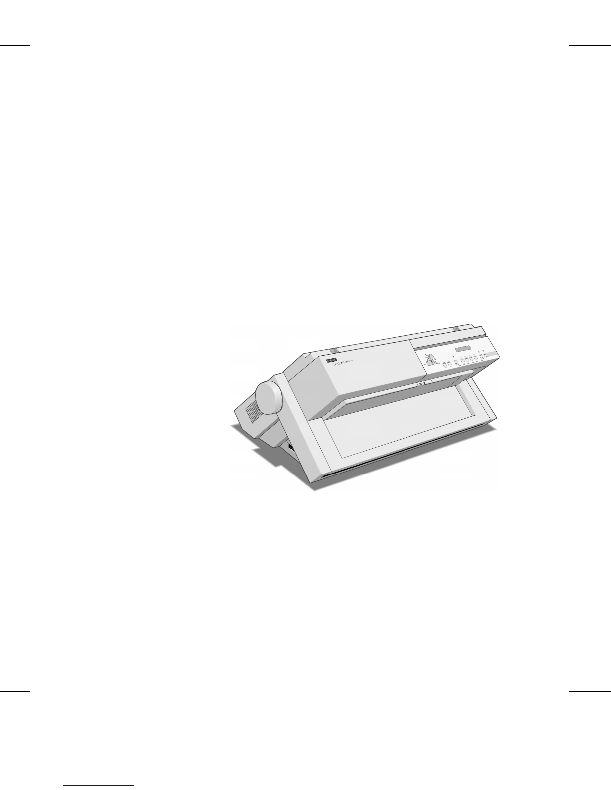
DIGITAL Matrix Printer LA400plus
1
User Guide
Order Number: EK-LA45E-UG-001


Digital Matrix Printer LA400plus
Setting Up Your Printer
Digital Equipment Corporat ion
Maynard, Massachusetts

First Printing, September 1998
The contents of this guide may be revised without prior notice and without obligation to
incorporate changes and improvements into units already shipped.
Every effort has been made to ensure that information included here is complete and
accurate at the time of publication: however, Digital Equipment Corporation cannot be
held responsible fo r errors and omissions.
No part of this guide may be reproduced or translated, stored in a database or retrieval
system, or transmitted, in any form or by any means, electronic, mechanical,
photocopying, recording, or otherwise, without the prior written permission of Digital
Equipment Corporation 1998. All rights reserved.
The following are trademarks of Digital Equipment Corporation: LA400plus MultiPrinter
and the Digital logo.
Centronics is a trademark of Centronics Data Computer Corporation. IBM PC, IBM
Proprinter X24E and IBM Proprinter XL24E are trademarks of International Business
Machines Corporation. ESC/P2 is a trademark of Seiko Epson Corporation. Microsoft is a
registered trademark an d MS-DOS, Windows and Microsoft BASIC are trademarks of
Microsoft Corporation.
Other products names mentione d in this guide may also be trademarks of their resp ective
companies.
As an Energy Star TM Partner. Digital Equipment Corporation has determined that this product
meets the Energy Star TM guidelines for energy efficiency.

Table of Contents
Introduction
System Requirements ...................................................................................................................1
Digital Environment...............................................................................................................1
PC Environment.....................................................................................................................1
Installation Procedure...................................................................................................................2
Step 1 - Unpacking the Printer
Where to Place the Printer....................................................... ...... ...... ...... ...... ...... ...... ...... ...........3
Environment...........................................................................................................................3
W ork Location........................................................................................................................3
Preparing the Printer.....................................................................................................................5
Checking Ca rton Contents ................................ .............................................................. .......5
Locating the Printer Parts.............................................................................................................6
Removing the Shipment Locks ....................................................................................................8
Step 2 - Mounting the Push Tractor Unit
About Paper Feeding and Paper Paths........................................................................................11
Paper Path for Continuous Forms ......................................................................................11
Feeding Cut Sheets and Envelopes .....................................................................................11
Mounting the Push Tractor Unit in Front Position ..............................................................12
Position of the Push Tractor Locking Buttons.....................................................................14
Step 3 - Starting-up the Printer
Connecting the Printer to the Power Outlet................................................................................15
Powering-on the Printer.............................................................................................................. 17
Step 4 - Selecting the Display Language
Entering the Set-Up Mode..........................................................................................................18
Selecting the Language...............................................................................................................18
Step 5 - Installing the Black Ribbon Cartridge
Preparing the Cartridge...............................................................................................................20
Installing the Cartridge...............................................................................................................21
Step 6 - Loading Continuous Form
Loading the Paper.......................................................................................................................25
Step 7 - Printing your Fir st Page
Printing the Printer Self-Test Page .............................................................................................30
iii

Step 8 - Connecting your Printer to the Host System
Connecting your Printer to a Digital Environment.................................................................... 32
Connecting to the Computer, Server or Terminal................................................................ 32
Checking the Connection .................................................................................................... 33
Printing a Test Page from Your Host System...................... .... .... .. .... .... .... .. .... .... .... .. ....33
Connecting your Printer to a PC Environment.......................................................................... 34
Connecting to the PC........................................................................................................... 34
Checking the Protocol ......................................................................................................... 35
What’s a Protocol..........................................................................................................35
Setting the Protocol ....................................................................................................... 35
Installing the Windows Printer Driver................................................................................. 36
Installing the Print e r Driver for Windows 3.x............... ................ .. ................ .. ................ ..36
Installing the Print e r Driver for Windows 95.............. ................ ................ .. ................36
Printing a Test Page............................................................................................................. 36
Printing a Test Page un de r Windows 3.x................. .. .. ................ .. ................ .. ..............36
Printing a Test Page un de r Windows 95.... ................ .. ................ .. ................ .. ..............36
iv

Introduction
This is a short guide to installing and setting up the DIGITAL Matrix Printer LA400plus to work
within a Digital or a PC environment. It also introduces some basic concepts defining the global
hardware and firmware organization of the print e r.
System Requirements
The following information details the requirements for a proper installation and functioning of
your printer.
Digital Environment
There are no specific requirements since your DIGITAL Matrix Printer LA400plus is a Digital
printer, especially designed and manufactured for perfect integration in the Digital environment.
PC Environment
Check the following interface definition and connectors:
Serial Interface Parallel Interface
- Version: DEC423 (RS423 compatible). - The parallel interface cable is not provided.
- Connector: Use a Digital MMJ adaptor. For
a 9 pins connector on your PC, use a
H8571-J Digital adaptor.
Use a Digital parallel cable: BC19M-06
(6 feet) or BC19M-10 (10 feet).
1

Installation Procedure
The installation procedure described in this guide concerns the use of standard continuous form
(simple part or thin multiple parts). We rec ommend that you first follow this step by step
procedure for getting to know your printer:
• Step 1 - Unpacking the Printer
• Step 2 - Mounting the Push Tractor Unit
• Step 3 - Starting-up the Printer
• Step 4 - Selecting the Display Language
• Step 5 - Installing the Black Ribbon Cartridge
• Step 6 - Loading Continuous Form
• Step 7 - Printing Your First Page
• Step 8 - Connecting your Printer to the Host System
Note:
For information about loading different types of paper, see Chapter 3 "Handling
Different Types of Paper" of the User Guide.
2

Unpacking the Printer
Where to Place the Printer
When choosing the location for your printer check the following:
Environment
• Away from any heat source and not exposed to direct sunlight.
• Avoid dusty, dirty or humid environment.
Work Location
• Choose a flat, stable surface near to the host system or PC.
• Avoid obstructing the openings of the casing (located on both side of the casing) for correct
ventilation.
• You need an independent power outlet to which you can connect the printer nearby.
• Avoid interference between cables at the rear of the printer and loaded continuous form.
Step 1
3
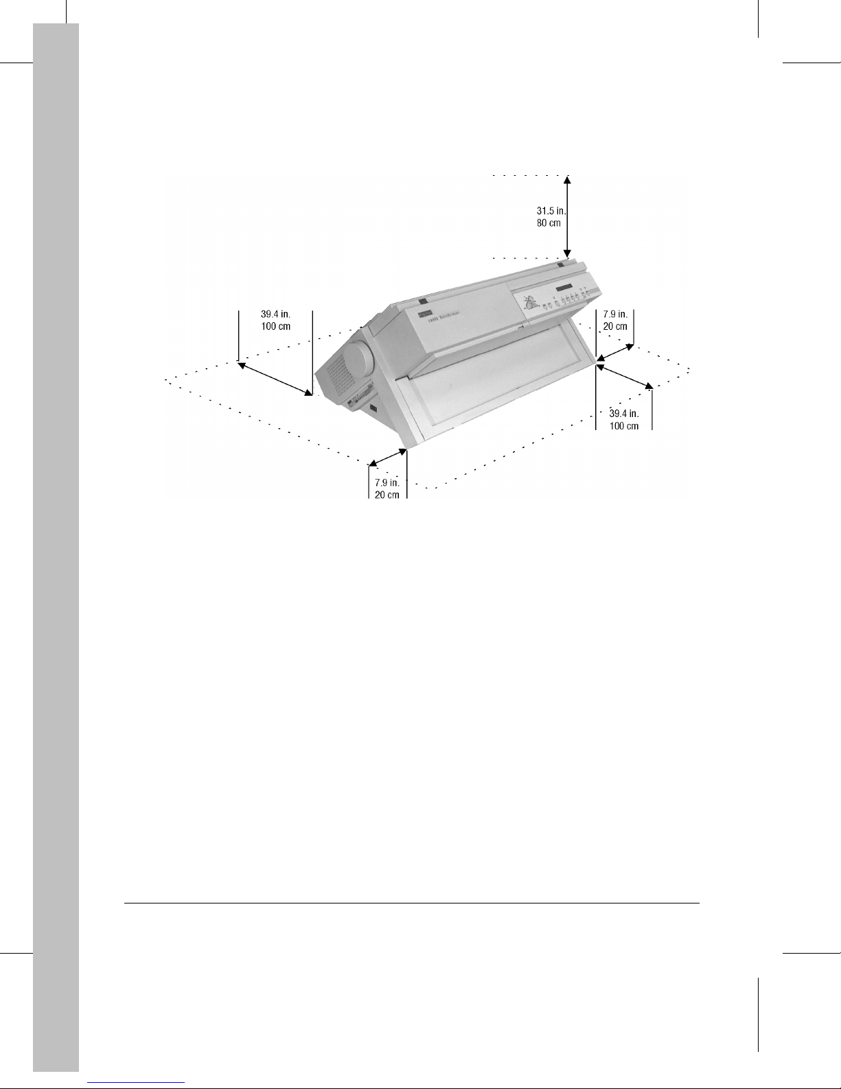
We recommend that you free up some space around the printer as shown in the following picture ,
to allow automatic paper routing for continuous form and easy access:
Free Space Dimensions
4
Preparing the Printer
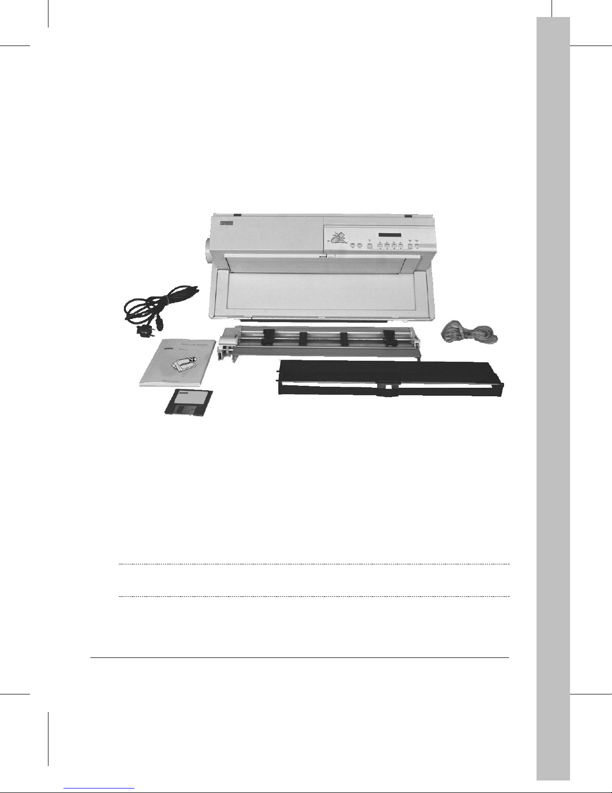
Checking Carton Contents
1. Take out the accessor ies from the foam blocks and remov e the blo ck s fro m the printer.
2. Check if all printer parts are present and undamaged according to the following list.
1
2
7
3
5
4
DIGITAL Matrix Printer LA400plus
1
Power cable
2
"Setting Up Your Printer " + User Guide
3
Printer driver disk (Windows 3.1 and
4
Windows 95)
3. Place the printer at its location.
Note:
Keep the carton and all the packing materials in case you have to transport the printer,
relocate it, or return it to Digital Services for maintenance.
Carton Contents
Push tractor unit
5
Black ribbon cartridge
6
Serial interface cable
7
6
5
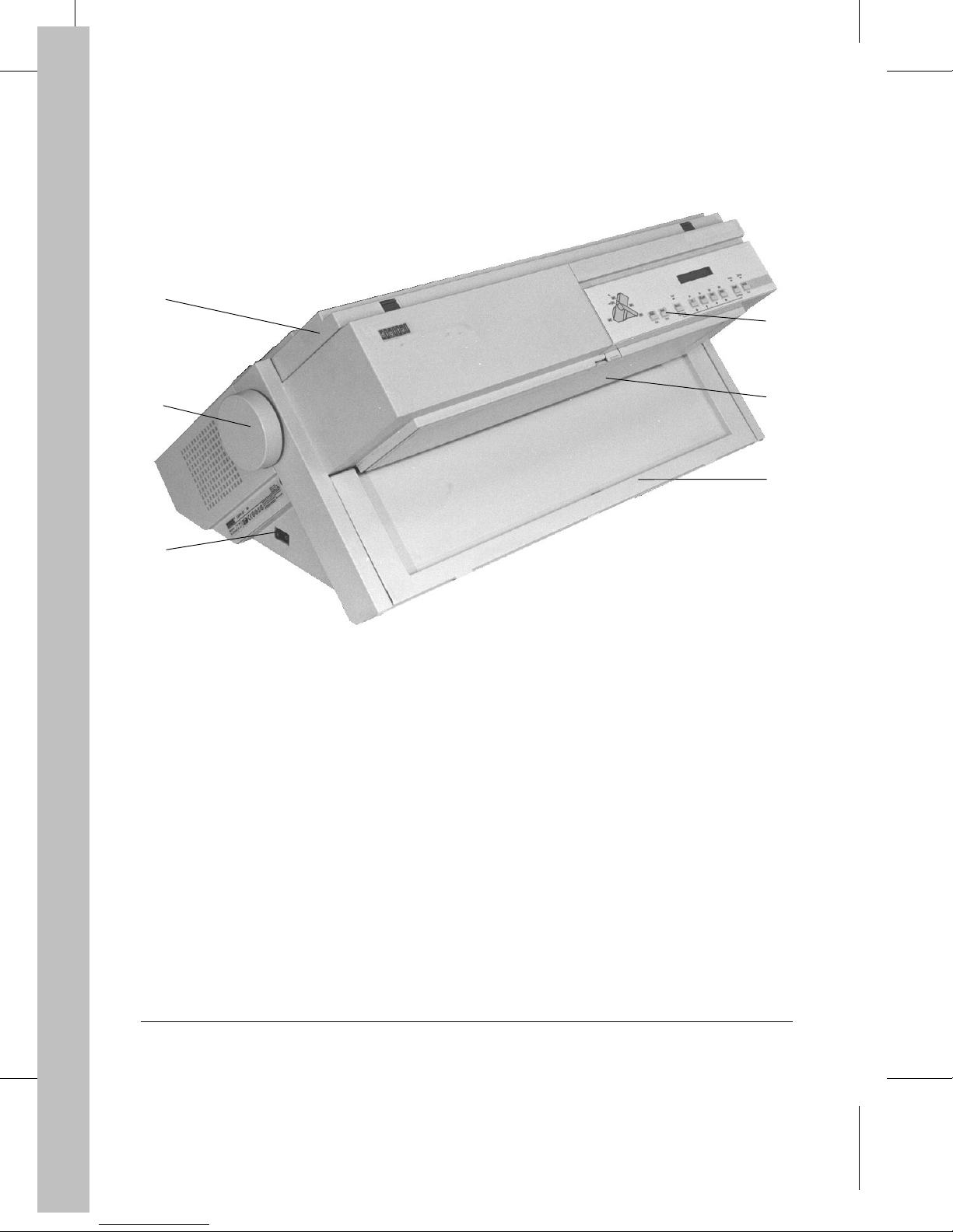
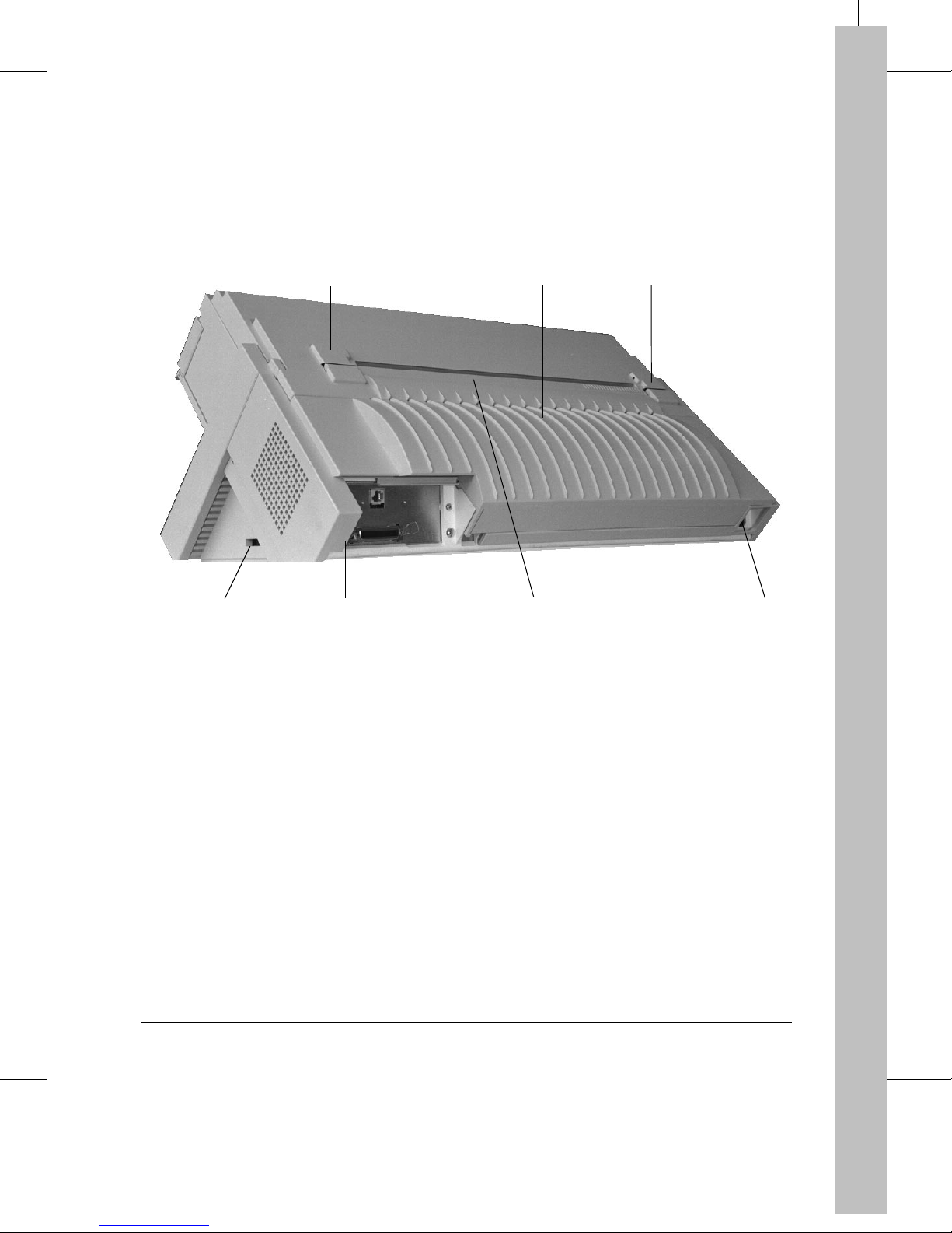
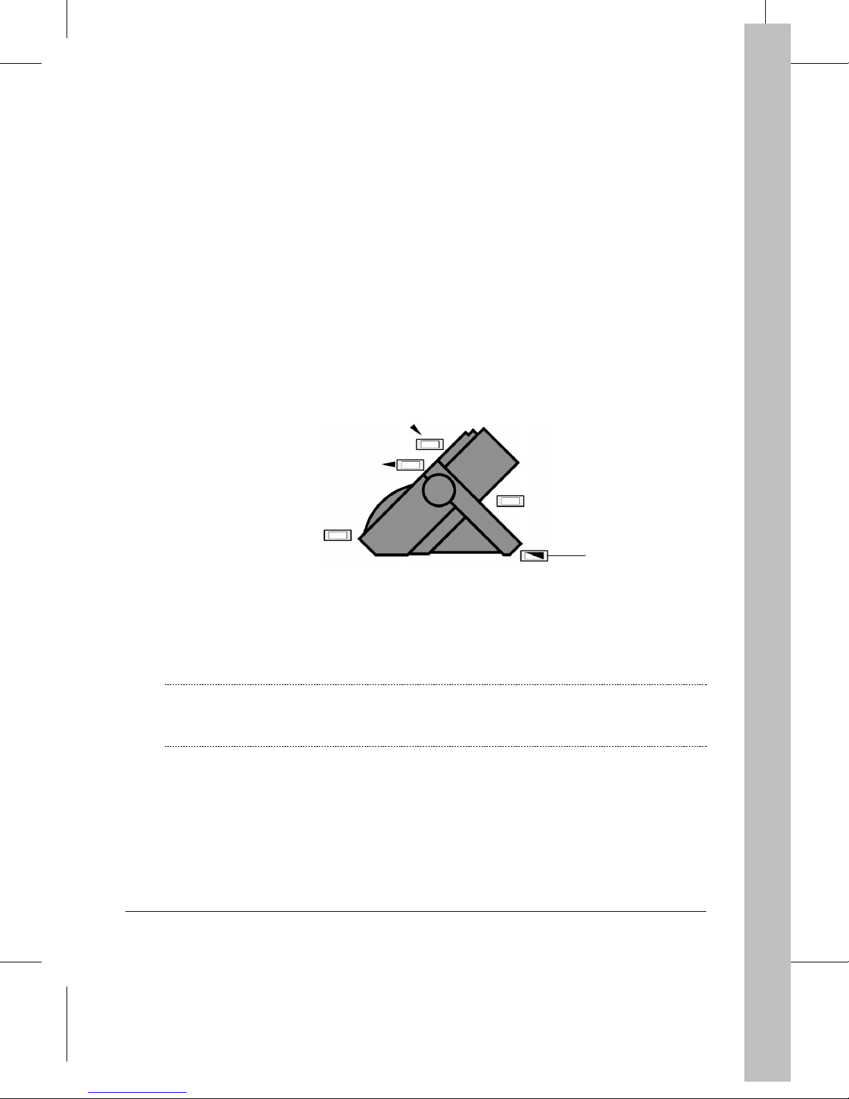
Locating the Printer Parts
3
4
2
1
Power switch
1
Platen knob
2
Top cover
3
Operator panel
4
Cut sheet stand
5
Front slot cover
6
5
6
d400-c02
6
!
!"
0
Rear slot cover
7
Power socket
8
Interface connectors
9
9
7
Slot for optional Set-Up ca rd or font card
0
Pull tractor mechanism covers
!
Large rear cover
"
8
d400-c03
7
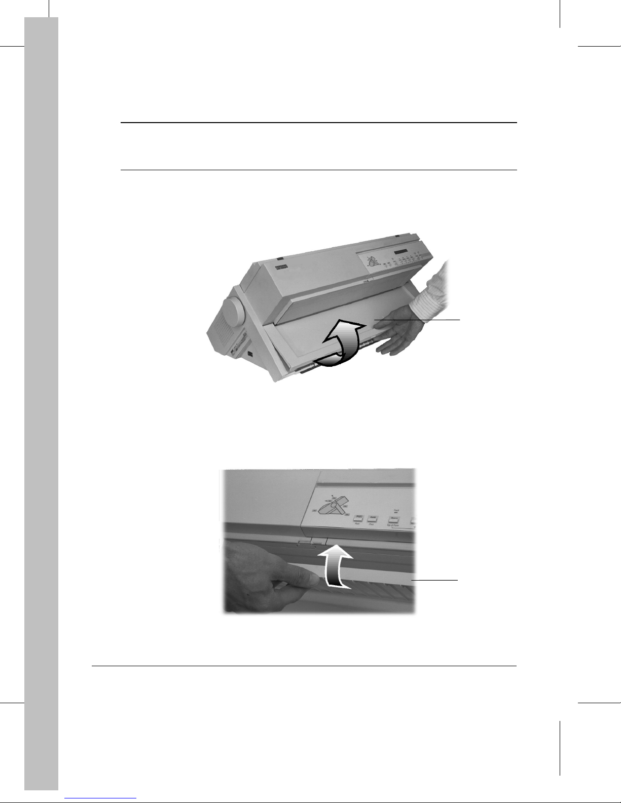
Removing the Shipment Locks
Caution:
1. Open the front slot cover
Before performing any operation, you must remove the four orange shipment locks.
Keep them in order to reuse them in case you have to transport the printer, relocate it
or return it to Digital Services for maintenance.
by pulling it up at the center of the cover.
①
Opening the Front Slot Cover
1
d4001c04
2. Lock the front slot cover
8
to the printer casing by pushing on its center to the top.
①
Locking the Front Slot Cover
1
d4002c05
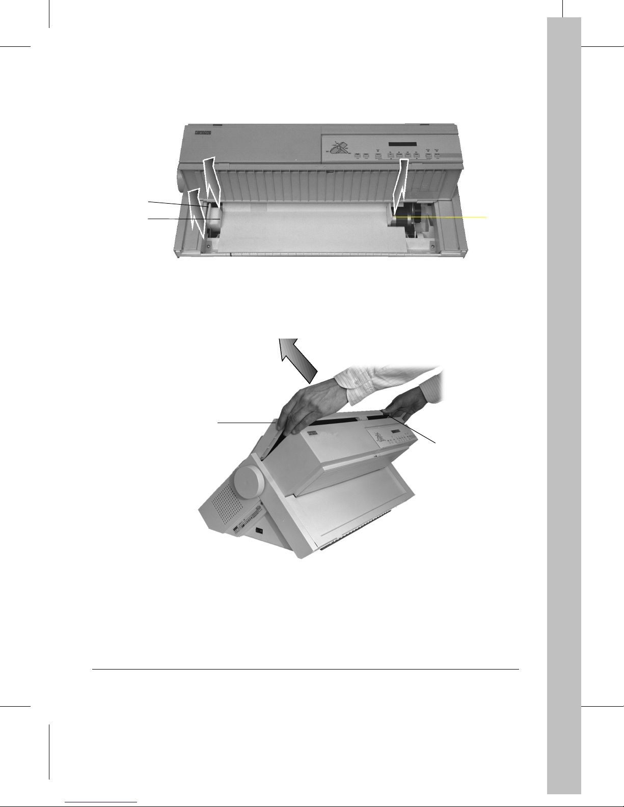
3. Remove the basic assembly shipment locks ②, ③ and ④.
2
3
Removing the Basic Assembly Shipment Locks
4
d4001c06
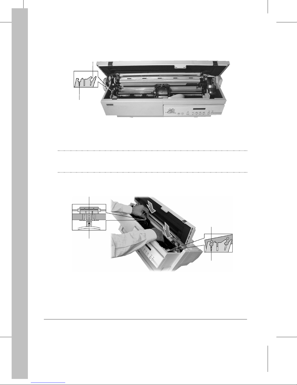
4. Open the top cover
5
by pressing the two gray locking buttons ⑥.
⑤
Opening the Top Cover
6
d4001c07
9
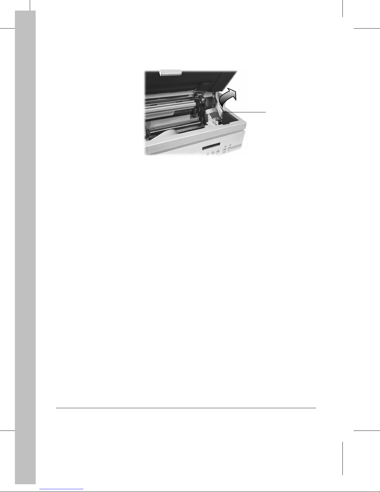
5. Remove the carriage motor shipment lock ⑦.
Removing the Carriage Motor Shipment Lock
7
d4001c08
6. Close the top cover
⑤
.
10

Mounting the Push Tractor Unit
About Paper Feeding and Paper Paths
The DIGITAL Matrix Printer LA400plus is designed for use with a wide range of paper types,
from continuous form (simple part, multipart or adhesive labels) to cut sheets (simple part or
multipart) and envelopes.
Seve ral paper feeding devices are availabl e de pending on the type of pa per you intend to use.
Paper Path for Continuous Forms
A paper path is ma in l y defined by:
– the paper feeding device used
– the position of the paper feeding device on the printer
Two paper feeding devices are available:
– the Push tractor unit (standard)
Step 2
– the Pull tractor unit (option)
You can mount the feeding devices in two positions:
– the Front position (under the front slot cover)
– the Rear position (under the rear slot cover)
The most common paper path uses the Push tractor unit mounted in the Front position and is
compatible with most of the paper types. This paper path, called Push-Front, is factory set in the
printer as the path to be used at first power-on.The following instructions explain how to set up
this paper path.
Feeding Cut Sheets and Envelopes
The Cut sheet stan d of you r DIGI TAL Matrix Printer LA400plus defines the Manual paper path
available for cut sheets and envelopes.
Note:
For more information about feeding different types of paper, see Chapter 3 "Handling
Different Types of Paper" of the User Guide.
11
Mounting the Push T ractor Unit in Front P osition
Warning:
1. Remove the Push tractor unit ① from its plastic packet.
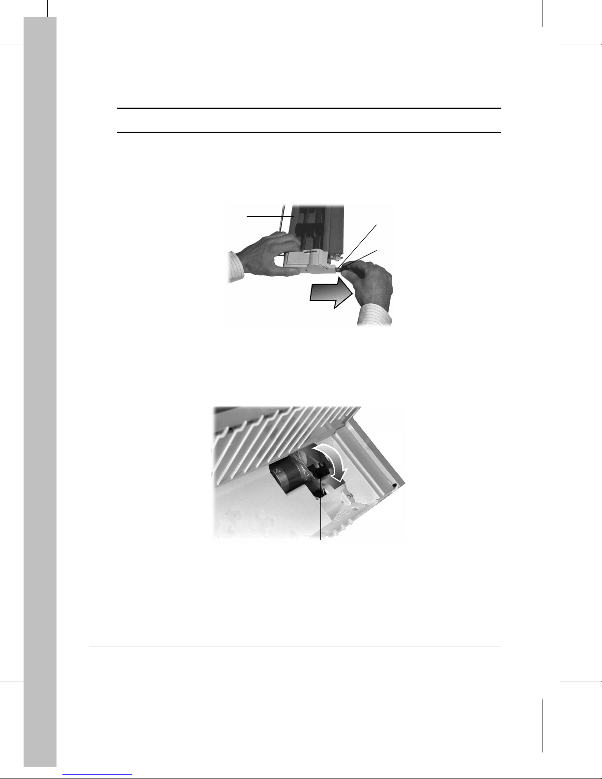
2. Remov e t he bl ack plastic prote ct ion
The printer must be powered-off before you start this procedure.
from the elect rical connect o r ③.
②
1
Removing the Protection from the Electrical Connector
3. Disengage the plastic protection
the picture.
from the feeding motor gear wheel, rotating it as shown in
④
3
2
d4001a02
12
4
Disengaging the Gear Wheel Protection
d4001a04
4. Identify the place ⑤ of the Push tractor unit ① in the printer with the help of this figure. The
electrical connec tor
must be on the right.
③
5
3
1
Identifying the T r actor Unit Place
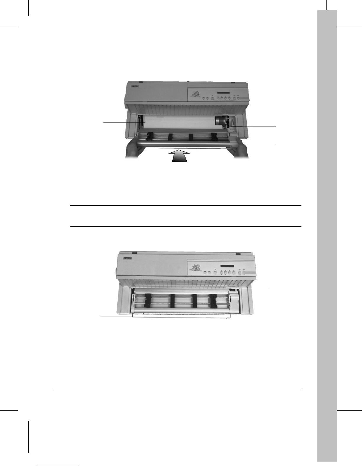
5. Mount the Push tractor unit
printer casing and inserting the electrical connector into the corresponding plug on the printer.
Warning:
Ensure that the paper separ at or ⑥ is correctly retracted into the tractor unit casing.
Otherwise, paper may not be loaded.
in its place ⑤, aligning both its left and bottom sides with the
①
1
d4001a54
6
d400-a58
Mounting and Aligning the Push Tractor Unit in its Place
13
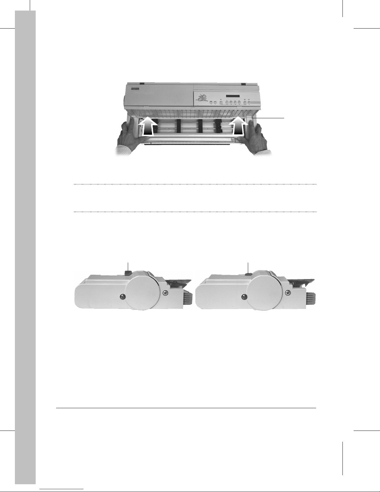
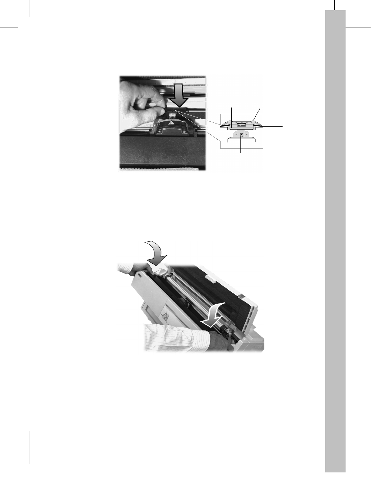
6. Push both the left and right sides of the Push tractor unit ① upward, until it is fully engaged.
1
d4001a07
Engaging the Push Tractor Unit
Note:
7. Check that the paper separator
The Push tractor is en gaged when you feel and he ar th e cli c k of both left and right
locking buttons
shown in the following picture.
. The Push tractor locking buttons must be in the up position as
⑦
seats inside the printer and does not overhang the casing.
⑥
Position of the Push Tractor Locking Buttons
7
d4001a08
Right Position (up)
7
d4001a09
Wrong Position (down)
14
Starting-up the Printer
Connecting the Printer to the Power Outlet
Step 3
Warning:
The manuf a cturer declines all respo ns ib il it y for accidents to pers on s or da mage to the
printer arising from the non-observance of the following procedure.
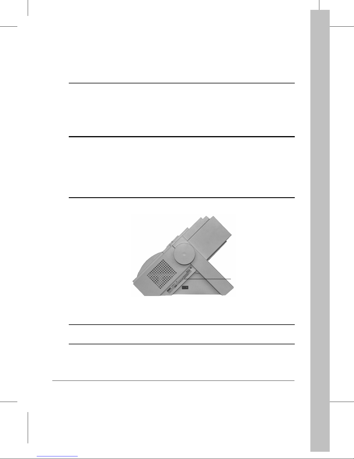
Make sure the power outlet supplies the voltage indicated on the electrical data plate
on the left side of the printer (when facing th e op er ator panel), abov e the po w er
①
switch. If the electrical data plate indicates a different voltage, call your dealer
immediately. DO NOT, UNDER ANY CIRCUMSTANCES, CONNECT OR SWITCH
ON THE PRINTER.
1
Electrical Data Plate
Caution:
BEFORE connecting the printer to the power outlet and / or switching it on, read all
the following points carefully.
15
To connect the printer to the power outlet:
1. Make sure that the plug on the power cable is of the type accepted by the power outlet you
intend to use; if it is not, call your dealer.
Do NOT attempt to change the plug yourself.
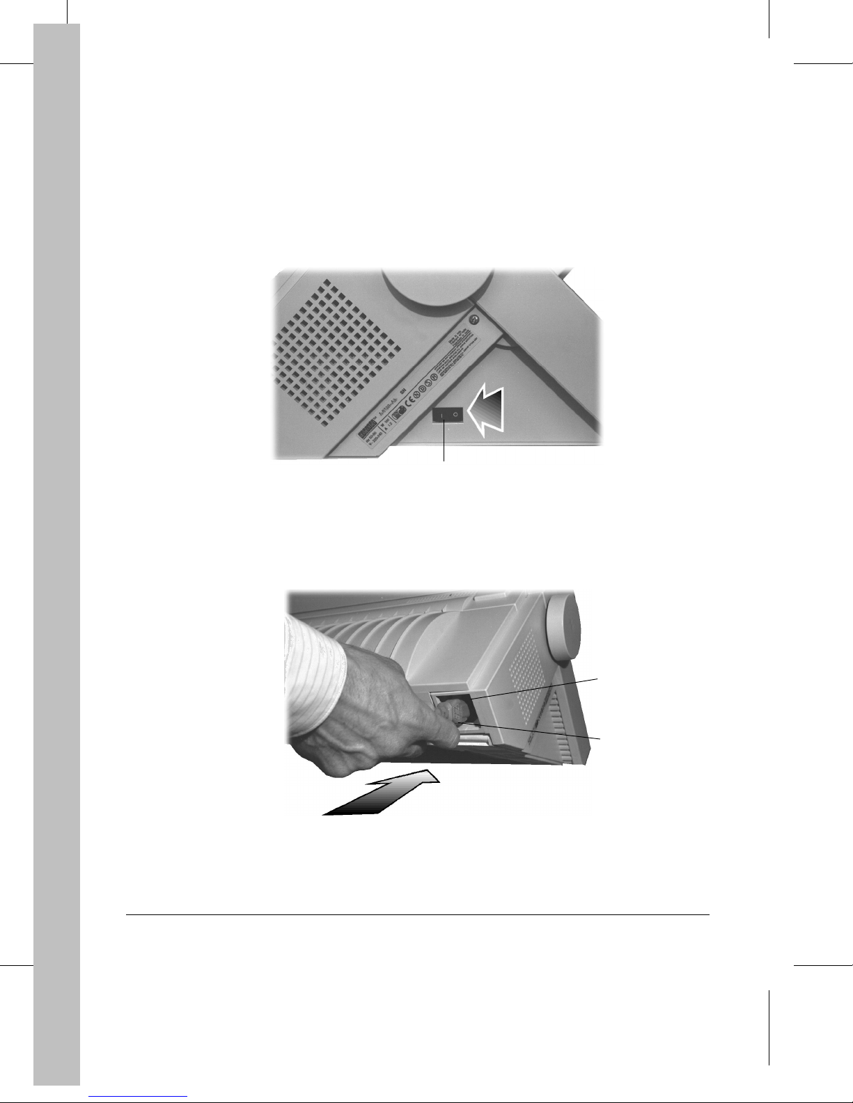
2. Make sure the printer is powered-off. The power switch ② is in the O position.
2
Checking the Printer is Powered-off
3. Plug the power cable
4. Plug the other end of the power cable into the power wall socket.
(into the power socket ④ at the back of the printer).
③
Plugging the Power Cable
d4001c10
4
3
d4001c11
16
Powering-on the Printer
1. Check all the points in the previous step.
2. ONLY if no further intervention is required, power-on the printer by pushing the power
switch to the position I.
When you po wer-on the printer:
• It undergoes a series of internal checks, including all sensors information (paper detection etc.).
• The messages "Starting Up...", "Testing...", then "Ready M1-Aut" appear on
the display.
Ready
• The
• Since no paper is detected by the printer, the printer beeps, the
indicator for t h e Push-Front paper pa th
should be loaded.
indicator is on.
Fault
indicator is on and the
blinks slowly, indicating the paper path where paper
①
1
Push-Front Path Indicator
If any faults are found during the initialization, the
messages "Printer failure" and "Call Service" appear alternately on the display.
Call your dealer or the technical assistance service.
Note:
If you have not properly closed the top cover, the printer beeps and the message
"Top cover open" appears. Initialization starts again after correctly closing the top
cover.
Fault
indicator blin ks ra pi d l y an d t he
17

Step 4
Selecting the Display Language
Entering the Set-Up Mode
Your DIGITAL Matrix Printer LA400plus allows you to choose the language used for the
different messages displayed.
To select the display language, you need to enter Set-Up mode. The following procedure will help
you learn how Set-Up mode works, even if you don’t need to change the display lan guage.
Selecting the Language
To select the language:
1. Press the
The message "MACROS" appears on the display an d the
2. Press the R button.
The message "INSTALLATION" appears.
3. Press the D button.
The message "LANGUAGE" appears.
4. Press the D button.
The message "* English" appears. The * symbol indicates that English is the
current language for displaying the messages.
5. Select your language by using the L or R buttons.
The different available languages app ear on the display, each time yo u pr es s on e of th ese
buttons.
Set-Up
button.
Set-Up
indicator blinks slowly.
18

6. Once the desired language is displayed , confirm your choice by pressing the
The * symbol appears to confirm your choice.
Sel/Save
button.
7. Press the
Exit
button to exit Set-Up mode.
The message "Save config." appears, indicating that you ar e go ing to sa ve your new
configuration.
– To permanently save your choice in the current M1 macro, press the
Sel/Save
button.
The new language selection will still be active at next power-on.
– To temporarily save your choice, press the
Exit
button.
The new language selection will be lost at next power-on. The previous language selection
will be active.
– To cancel your modification and return to the previous configuration, press the R button.
The message "Restore Macro 1" appears. Pr ess the
Sel/Save
button.
19
Installing the Black Ribbon Cartridge
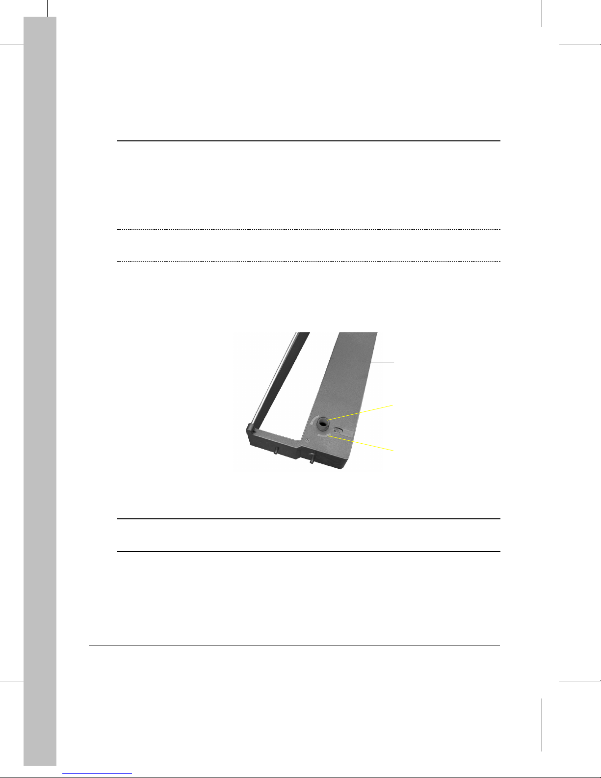
Preparing the Cartridge
Step 5
Note:
1. Remove the black ribbon cartridge
2. Turn the ribbon feed knob
If you have the color mechanism option, see Appendix A "Supplies and Options" to see
how to install the color ribbon cartridge.
in the engraved arrow direction ③ to take up slack in the
②
ribbon.
Taking Up Slack in the Ribbon
from its plastic packet.
①
1
2
3
d4001b43
Caution:
20
To avoid damaging the ribbon, do not turn the ribbon feed knob in the wrong
direction.
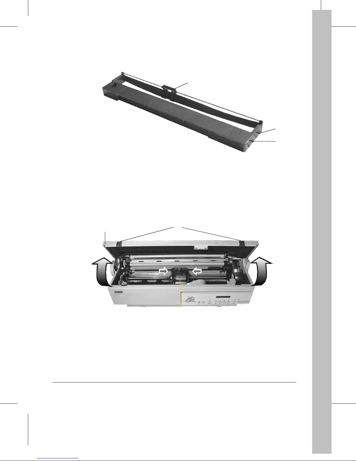
3. Locate the front mounting pins ⑤, the back mounting pins ⑥ and the ribbon guide ⑦.
7
The Ribbon Cartridge
Installing the Cartridge
1. Open the top cover ① by pressing the two gray locking buttons ②.
The print head
moves automatically to the center of the printer.
③
6
5
d400-b43
1
2
3
Print Head Position for Installing the Ribbon Cartridge
d4001b20
21
2. Locate the front ④ and back ⑤ locking grooves of the left and right cartridge supports.
5
4
Aligning the Cartridge Pins with the Cartridge Supports
d4004b20
3. Align the cartridge front mounting pins
Note:
4. Align the center of the ribbon guide
In order to correctly position the left front mounting pin, turn the ribbon feed knob of the
cartridge according to the engraved arrow, until the mounting pin is in contact with the
cartridge support. See the following picture.
⑦
7
8
Positioning Cartridge/Aligning Ribbon Guide with Print Head
on the front locking grooves on both sides.
⑥
with the center of the print head nose ⑧.
66
4
d4002b29
22
5. Slide down the ribbon guide ⑦ on the print head nose ⑧ so that the ribbon ⑨ is inserted
between the print head nose
and the print head guide ⑩.
⑧
7
0
9
8
d4002b15
Inserting the Ribbon Guide
6. Position the back mounting pins on the back locking grooves
7. Push down t he ri bb on cartridge above the mo un t ing pi ns area so that the pins fully en gage the
locking grooves.
of the cartridge supports.
⑤
d4001b41
Locking the Ribbon Cartridge
23
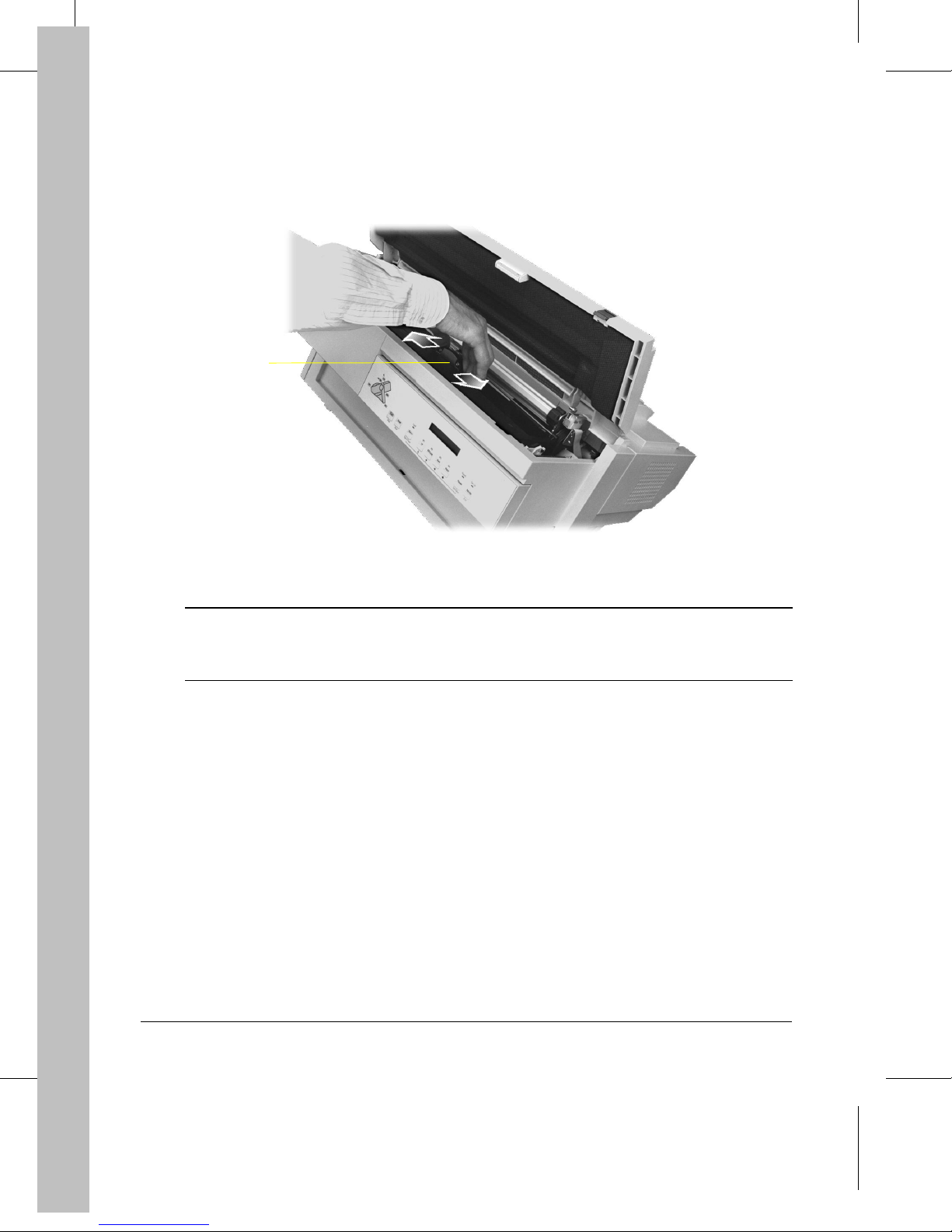
8. Turn the ribbon feed knob again in the direction of the arrow to take up slack in the ribbon.
9. To ensure that the ribbon guide
print head
along the carriage bar.
③
3
Checking the Ribbon Cartridge Installation
runs freely along the ribbon, manually move the
⑦
d4001b38
Caution:
10.Close the top cover
24
This operation can be done only when you are installing the ribbon cartridge for the
first time. If you have been already printing and you are going to replace the ribbon
cartridge, this operation must be done only after the print head has cooled down.
.
①
 Loading...