

Digital Equipment LA 120 User Manual
USER
GUIDE

EK-LA120-UG-003
'
1
st
Edition,
2nd
Edition, January
3rd Edition,
September
1979
June
1979
1978
Copyright © 1978,
Digital
The material in
Equipment
this
purposes and is
manual is
subject
1979
Corporation
for
to
change
notice.
Digital
responsibility
in
this
Equipment
for
manual.
Corporation assumes no
any errors
which
Printed in U.S.A.
This
document
8000
computerized
The
following
ment
Corporation, Maynard, Massachusetts:
DIGITAL
DEC
PDP
UNIBUS
was
set
on DIGITAL's DECset-
typesetting
are trademarks
DECSYSTEM-20
DIBOL
VAX
VMS
of
DECsystem-10 MASSBUS
by
informational
without
may appear
system.
Digital Equip-
OMNIBUS
OS/8
RSTS
RSX
lAS
CONTENTS
INTROD
CHAPTER
PART 1 GENERAL
UCTION
1
Operator's
Lights ................................................................................................................
Numeric
Local Control Keys .......................................................................................... 3
SET-UP Keys ................................................................................................... 4
Control Character Keys .................................................................................. 5
Control Keys .................................................................................................... 6
Other Keys ....................................................................................................... 6
Optional
Power
Cover I nterlock
Paper
Carriage
Tractor
Alarm
Testing and Troubleshooting the LA
Operator's Troubleshooting Table .............................................................
Sample LA
On/Off
Adjust
Adjust
Indicators
OPERATOR
USER
Console ......................................................................................... 1
Display .............................................................................................. 3
Numeric
Adjustment
120
Keypad ............................................................................. 7
Switch
Knob .......................................................................................... 8
Knobs ..................................................................................... 8
..................................................................................... 7
Switch
Lever ........................................................................... 8
............................................................................................. 9
Operators' Card ................................................................ 13
INFORMATION·
INFORMATION
................................................................................... 7
................................................... 1
120
.................................................
3
10
11
PART 2 DESCRIPTION
FORM SET-UP FEATURES .................................................................................
OF
Recommended Sequence
SET-UP
Selecting
Mode
............................................................................................... 18
Lines Per Inch .............................................................................. 19
iii
LA
120
for
Setting
FEATURES
Up a New
........................................
Form ..........................
15
15
15
Setting
Top
Top and
Displaying Line
Setting
Setting
Clearing Vertical
Setting
Form Length ....................................................................................
of
Form
(TO
F)
........................................................................................
Bottom
Top Vertical
Bottom
Single or
Margins and Vertical Tabs ............................................
Number
Vertical
Margins
Multiple
of
Margin
Margin
a Vertical Tab or
.......................................................................
.................................................................
Margin
.............................
............................................................................
Vertical Tabs ...................................................
Clearing a Single Vertical Tab ....................................................................
Clearing all Vertical Tabs .............................................................................
Characters Per Inch (Horizontal Pitch) ......................................................
Horizontal
Displaying Column
Setting Left and Right
Clearing Left and Right
Margins
and Tabs .....................................................................
Number
of
Margins
Margins
a Horizontal Tab
or
Margin
..................
..................................................................
................................................................
Setting Horizontal Tabs ...............................................................................
Clearing a Single Horizontal Tab ...............................................................
Clearing all Horizontal Tabs ........................................................................
OPERATOR COMFORT FEATURES ..................................................................
Auto
Repeat ..................................................................................................
Last Character
Bell
Volume
View
.....................................................................................
...................................................................................................
Key Click ........................................................................................................
COMMUNICATION
FEATURES .........................................................................
Line/Local. .....................................................................................................
Baud Rate (Speed) .......................................................................................
Answerback
Transmitting or Printing
Entering/Deleting
Auto
Answerback
..................................................................................................
the
Answerback
Answerback
Message .................................................
Message ...............................
.........................................................................................
Buffer Control ...............................................................................................
Keyboard and Printer Character
Printer Character
Auto
Disconnect ...........................................................................................
Set
...................................................................................
Set
.........................................................
Local Echo .....................................................................................................
Auto
New
Line at Right
Auto
Line Feed .............................................................................................
Modem
Half
...........................................................................................................
Duplex (HDX) Initial Calling State ....................................................
Margin
.................................................................
Secondary Channel ......................................................................................
Parity and Data
Printer
XON/XO
New
FF
Alternate
Alternate
Selecting
Manually
Manually Deselecting
Break
Action
Bits
.....................................................................................
Line Character .......................................................................
....................................................................................................
Keypad
Character
Alternate
Mode
..............................................................................
Set
..............................................................................
Character Set. ............................................................
Selecting APL. .............................................................................
APL
.........................................................................
.................................................................................................
20
21
22
22
23
23
24
24
25
25
25
27
27
28
28
29
29
29
30
30
31
31
32
32
33
34
36
36
37
37
38
39
39
40
41
41
42
42
.43
43
44
.45
45
46
47
47
47
48
48
iv
STORE, RECALL,
Factory Stored
Store/Reca
Status
AND
STATUS FEATURES ..................................................
Settings
II
..................................................................................................
..............................................................................
.............................................................................................................
Self-Test Feature .......................................................................................... 53
49
50
51
52
PART 3 RIBBONS,
FORMS,
AND
IMPRESSIONS
.................................
I nstalling Ribbon ..........................................................................................
Print I mpression
Adjustment
.....................................................................
Loading Paper/Forms ..................................................................................
Reloading Paper/Forms ..............................................................................
CHAPTER
2
INSTALLATION,
INTERFACE,
AND
SPECIFICATIONS
INSTALLATION
AND
CONFIGURATION .........................................................
Unpacking and Inspection ..........................................................................
Packing Procedures .....................................................................................
Voltage
Selector
Switch
..........................................................................
Checkout Procedure ....................................................................................
Answerback
INTERFACE
Jumper
....................................................................................
INFORMATION
..............................................................................
E IA Interface .................................................................................................
EIA Cables .....................................................................................................
1M
PEDANCE
OF
TERMINATOR ........................................................................
Rise and Fall Times ......................................................................................
Open Circuit Voltages ..................................................................................
LA
120
SPECIFICATIONS ...................................................................................
54
54
54
55
56
59
60
61
61
62
62
63
63
63
65
65
65
66
CHAPTER
3
PROGRAMMER
INFORMATION
GENERAL ...............................................................................................................
ESCAPE SEQUENCE ............................................................................................
Printer Character Sets ...............................................
Opti onal
Active
Linefeed
Cha
racter Sets ..............................................................................
Column and
Newline
Active
Mode
Line ..................................................................
..............................
'"
'"
...............................
.............................................
Horizontal Pitch ............................................................................................
Horizontal
Margins
.......................................................................................
H orizonta I Tabs .............................................................................................
Vertical Pitch .................................................................................................
Form Length ........................................................................
Vertical
Margins
...........................................................................................
'"
.......................
Vertical Tabs .................................................................................................
PRODUCT IDENTIFiCATION ..............................................................................
Alternate
Control Characters ......................
APL
Keypad
Mode
..............................................................................
'"
..............................................................
Character Set .......................................................................................
Sample Form SET-UP Using Escape Sequences ....................................
Synchronization ............................................................................................
71
72
73
74
74
75
75
76
76
77
78
78
78
79
79
80
83
84
84
v
FILL
TIME
Vertical
FORMULAS .......................................................................................
Horizontal
Movement
Movement
..................................................................................
.......................................................................................
Keyboard Operation .....................................................................................
Auto
Repeat ..................................................................................................
Printable Character Keys ............................................................................
Control Character Keys ...............................................................................
Optional
Auxiliary
Keypad ..........................................................................
85
85
86
86
86
86
87
89
CHAPTER
FU
LL DUPLEX (FOX) ............................................................................................
4
COMMUNICATIONS
Full Duplex Connection Requirements .....................................................
Full Duplex Break .........................................................................................
Full Duplex Disconnect Conditions ...........................................................
HALF
Restraint
DUPLEX (HDX) ..........................................................................................
Mode
vs Speed Control
Mode
..................................................
Initial Direction Determination ..................................................................
Reverse Channel. ..........................................................................................
Modem
Request
Delay ...............................................................................................
to
Send Delay ................................................................................
Turnaround Characters ................................................................................
Half Duplex Break ........................................................................................
Loss
of
Data Set Ready ...............................................................................
Half
Duplex Disconnect ..............................................................................
MODEM
SET-UP FEATURE DESCRIPTION ....................................................
GeneraL ..........................................................................................................
Half Duplex ....................................................................................................
EFFECTS OF PAPER OUT ...................................................................................
CHAPTER
5
OPTIONS
93
93
93
93
94
94
94
95
95
95
95
95
96
96
96
96
97
98
20
mA
LA
12X-AL
............................................................................................... 101
Installation .................................................................................................. 1 0 1
Test
After
Installation ................................................................................
LA
12X-DL
CHAPTER
EXPANDED BUFFER ....................................................................
6
SUPPLIES
GENERAL ............................................................................................................
WARRANTY
........................................................................................... Back Cover
AND
ACCESSORIES
103
103
107
vi
~NT~ODUCT~ON
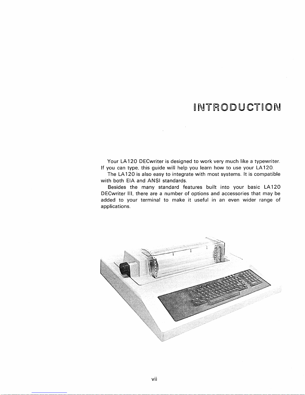
Your LA
If
you can type,
The LA
with
Besides
DECwriter
added
applications.
120
120
both
EIA and
III, there are a
to
your
DECwriter
this
is also easy
ANSI
the
many
terminal
is designed
guide
will
help you learn
to
integrate
standards.
standard features
number
to
of
make
to
work
very
how
with
most
systems.
built
into
options
it
useful in an even
and accessories
much
to
use
your
like a
your
It
is
basic LA
that
wider
typewriter.
LA
120.
compatible
120
may
be
range
of
vii


Operator
~n~ormation

CHAPT[E~
~
OP[E~ATO~
The LA
range
Part 1
familiar
Part 2 is
and provides a
The features have been grouped
feature is used:
120
of
features
of
with
•
Description
•
Description
•
Operator
•
Summary
Card)
for
DECwriter
that
the
operator's chapter is
the
features
Testing and Troubleshooting.
of
the
step-by-step
III
terminal
communicates
of
a terminal.
of
the
operator's
of
alarm and bell signals
LA
120
new
LA
120
procedure
~NFO~MAT~ON
is basically a
with
a computer.
for
the
console
DECwriter
D ECwriter III user.
III features (Operator Reference
for
using
to
help
typewriter
general user
It
explains each feature
the
feature.
the
user understand
with a wide
or
user already
when
a
•
Setting
•
Operator
•
Communication
• Store, Recall. and Status
•
Self
Part 3 describes
impression.
Test.
up a
comfort
how
form
to
load forms, change ribbons, and
adjust
the
print
2 OPERATOR
INFORMATION
PART
OPERATOR'S
1
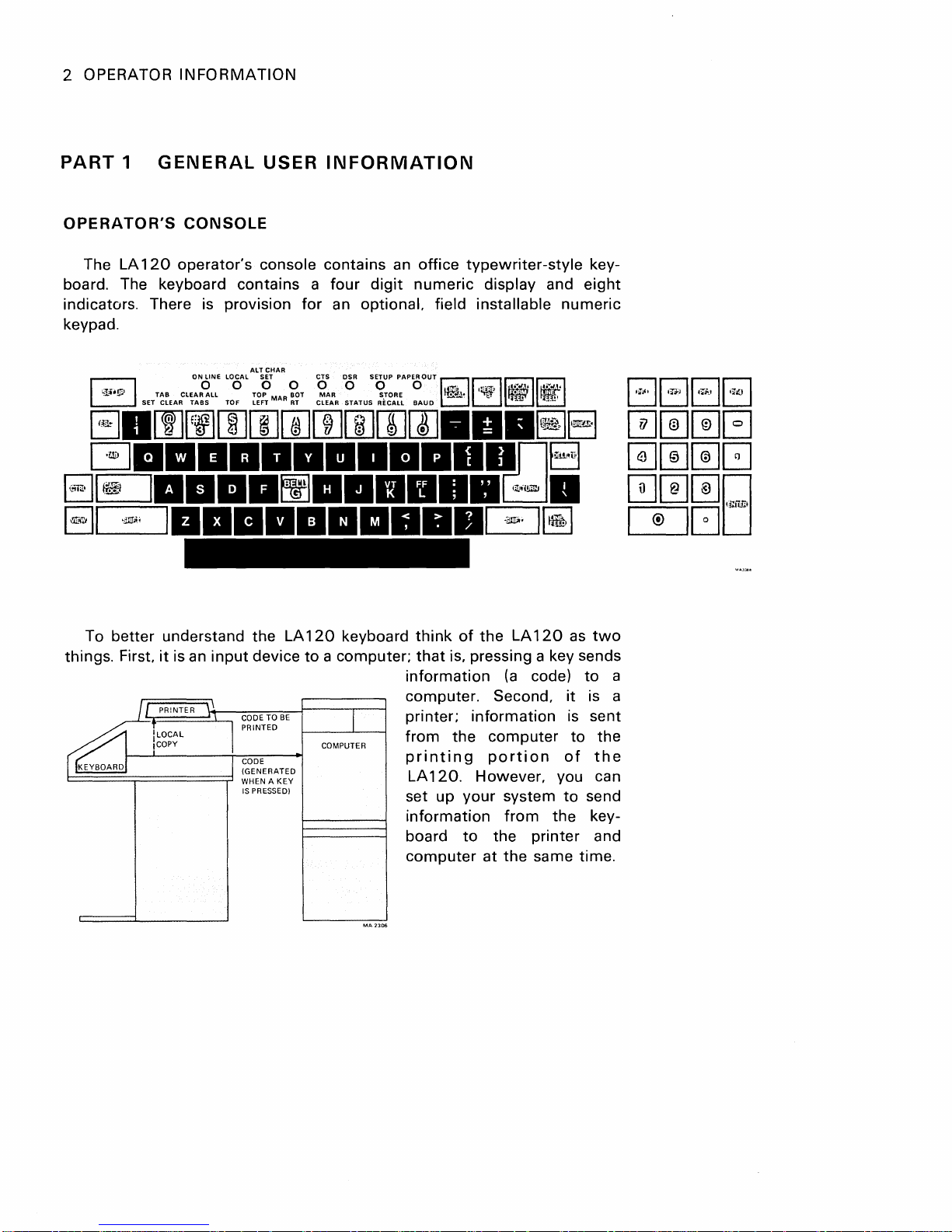
The LA
GENERAL
CONSOLE
120
operator's
USER
console contains an
board. The keyboard contains a
indicators. There is provision
for
keypad.
INFORMATION
office
four
digit
numeric
an optional. field installable
typewriter-style
display and
key-
eight
numeric
better
To
things. First,
/1
ILOCAL
,COpy
i
~
understand
it
is an
input
PRiNTER
11
"\
the
device
CODE
TO
BE
PRINTED
CODE
(GENERATED
WHEN A
KEY
IS
PRESSED)
LA
120
keyboard
to a computer;
I
COMPUTER
think
of
the
LA
120
that
is, pressing a key sends
information
(a
code)
computer. Second,
the
120.
information
computer
portion
However, you can
your
system
from
to
the
printer
at
the
same time.
printer;
from
printing
LA
set up
information
board
computer
as
it
is sent
to
of
to
the
two
to
is a
the
the
send
key-
and
a
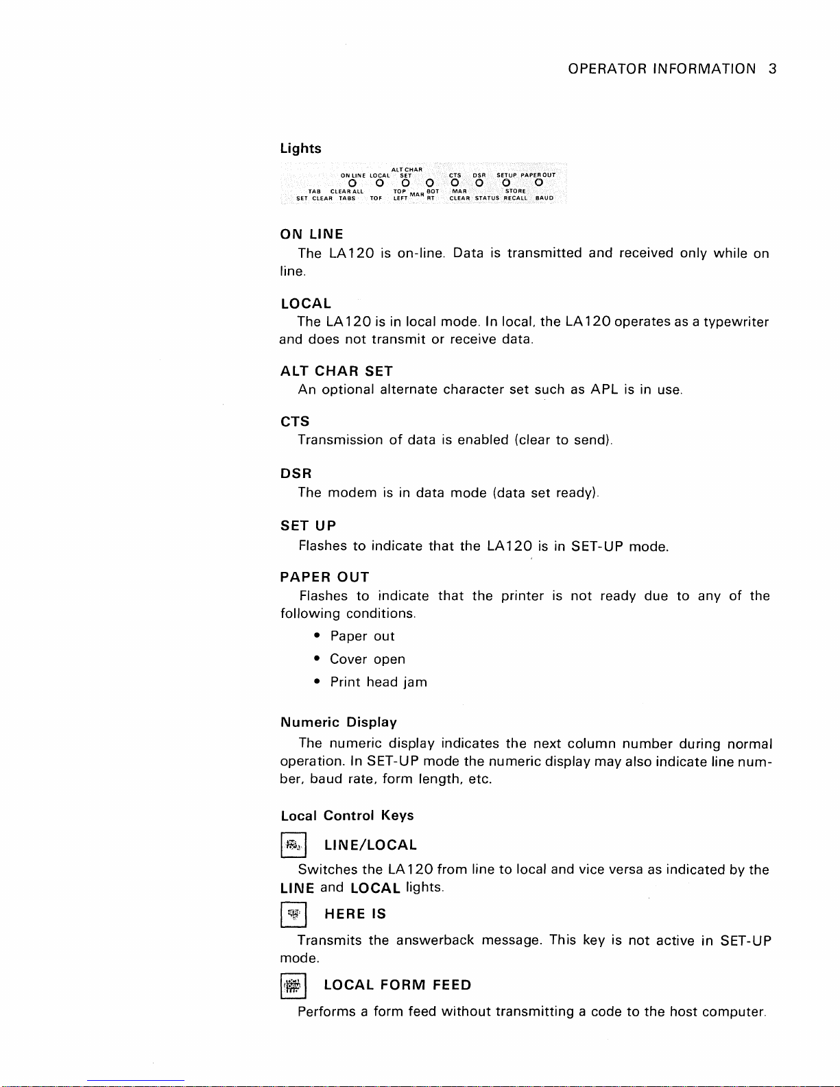
Lights
ON
LINE
LOCAL
SET
ON
The LA
o 0 0 0
T~~EARCL~~::LL
LINE
TOF
120
line.
LOCAL
The LA
and does
ALT
An
120
not
transmit
CHAR
SET
optional alternate character set such
CTS
Transmission
OPERATOR
ALT
CHAR
SET
[~:T
is on-line. Data is
MAR
CTS DSR
o 0 0 0
MAR
~~T
CLEAR
STATUS
SETUP
PAPER
OUT
STORE
RECALL
BAUD
transmitted
is in local mode. In local. the LA
or receive data.
as
of
data is enabled (clear
to
send).
INFORMATION
and received only
120
operates
APL
is in use.
as a typewriter
while
3
on
DSR
The
modem
SET
UP
Flashes
PAPER
Flashes
following
• Paper
OUT
is in data
to
indicate
to
indicate
conditions.
out
mode
that
that
• Cover open
• Print head
Numeric
The
Display
numeric
jam
display indicates
operation. In SET-U P mode
ber, baud rate,
Local
I~"I
Control
LINE/LOCAL
Switches
LINE
and
form
Keys
the
LA
LOCAL
length, etc.
120
from
lights.
(data set ready).
the
LA
120
the
printer
the
the
numeric
line
to
local and vice versa as indicated by the
is in SET-UP mode.
is
not
next
ready due
column
number
to
any
during
display may also indicate line
of
the
normal
num-
I~'
mode.
It~
I
HERE
Transmits the
I
LOCAL
IS
answerback
FORM
Performs a form feed
FEED
without
message. This key is
transmitting
a code
not
active in SET-UP
to
the
host computer.
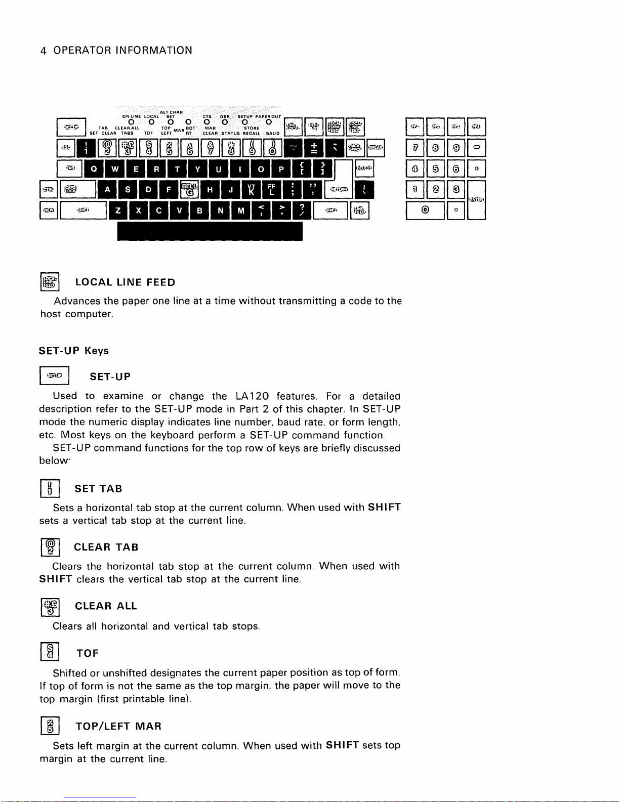
4 OPERATOR
INFORMATION
I~I
host
SET-UP
description refer
mode
etc.
below'
[]J
sets a
[IJ
SH
LOCAL
Advances
computer.
Used
the
Most
SET-UP
Sets a horizontal
vertical
Clears
I FT clears
the
Keys
SET-UP
to
examine or change the LA
numeric
keys on
command
SET
TAB
tab
CLEAR
the
horizontal
the
LINE
FEED
paper one line at a
to
the
SET-UP mode in Part 2
display indicates line number. baud rate.
the
keyboard perform a SET-UP
functions
tab
stop
at
stop
at the current line.
TAB
tab
stop at
vertical
tab
time
for
the
top
the
current column.
the
stop at
the
without
row
current column.
current
transmitting
120
features. For a detailed
of
this chapter. In SET-UP
of
keys are briefly discussed
When
line.
or
command
used
When
a code
form
length.
function.
with
SH
used
to
I FT
with
the
IfJ~1
[]]
If
top
[IJ
margin
CLEAR
Clears all horizontal and vertical
TOF
Shifted
top
of
form
margin (first printable line).
TOP/LEFT
Sets
left
at
ALL
or
unshifted designates
is
not
the
same
MAR
margin at
the
current line.
the
current column.
as
the
the
tab
current
top
stops.
margin.
When
paper
the
used
position
paper
with S HI
as
will
top
of
move
FT sets
form.
to
the
top
OPERATOR
INFORMATION
5
[I]
bottom
[I]
bottom
becomes
or
I
features.
[]]
the current SET -
[I]
split
BOT/RT
Sets
right
margin
MAR
Clears left and
margins. Left
the
form
length.
f:i
I
STATUS
Prints status message
STORE/RECALL
Recalls
Selects receive and
the
BAUD
transmit
MAR
margin at
at
CLEAR
right
maximum
stored SET-UP parameters.
UP parameters.
baud rates.
the
the
current line.
margins.
or
allowable
transmit
current column.
When
top
margin becomes
in the current characters per inch (pitch)
containing
baud rates.
When
used
with
currently selected values
When
When
1.
SH
Right
used
used
used
with
I FT clear.s
or
bottom
with
with S HI
SHIFT
SH
I FT sets
the
top
margin
of
SET-UP
stores
FT selects
and
Control
I~!>
~
SPACE
'_I
14!.L"ffi1
I
~'I
and
in addition
computer
Character
I
ESC
Generates the code
TAB
Generates the code for horizontal tab.
BAR
Generates
Generates
Generates
Generates
line feed sequence (in auto line feed mode).
In
half
the
BACK
the
DELETE
the
RETURN
the
duplex,
to
that
Keys
for
escape (Chapter 3).
code for space.
SPACE
code for backspace.
code
for
delete.
code for carriage return or
the
return key can also generate a turnaround character
its
normal code
it's
the
computer's
or
codes. The turnaround character tells the
turn
the
to
send data.
codes
for
a carriage return
I~I
LINE
Generates
FEED
the
code for line feed.
6 OPERATOR
I
"If·~
I
INFORMATION
ON
LINE LOCAL
SETTACBLEARCLETAARBOSAll
TOiOF
ALT
CHAR
SET
TLEDF?T
MAR?ROTT
CTS
DSR
SETUP
10
10
C~::R
STATUS
PAPER
OUT
0 0
::g:L~
BAUD
I~
~
II
,rriJ,
II~
'!:'f.
II~I
~
IfUlI
6.[I]~rn[IJ[]][I][[][]][]].II.~El
GII.IIII
EJ~
81
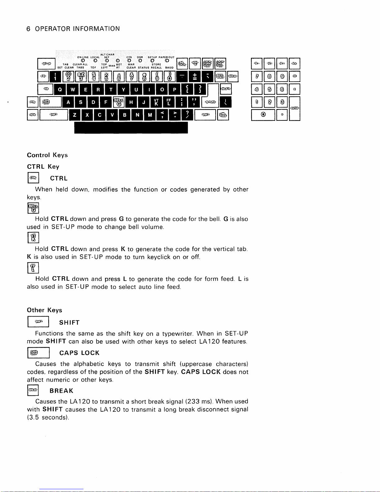
Control
CTRL
I~\
When
keys.
tj]
Hold CTR L
used in SET-U P
00
Hold
K is
also used in SET-UP
00
Hold
also used in SET -UP
••
L~~
I
••••
Keys
Key
CTRL
held
down.
down
mode
CTRL
down
CTR L down
••••
IIIIIIDn8
IIIItj]II.IIII
II
•••••
modifies
and press G
to
and press K
and press L
mode
the
function
to
generate the code
change bell volume.
to
generate
mode
to
turn
keyclick on or off.
to
generate
to
select auto line feed.
••
G:J.
~~
or
codes generated by
for
the bell. G is also
the
code
for
the
the
code
for
form
other
vertical tab.
feed. L is
Other
G
mode
Ie
codes.
affect
\QTiTE.\
with
(3.5 seconds).
Keys
SHIFT
Functions the same as
SH
I FT can also be used
\
CAPS
Causes the
regardless
numeric
B R
EA
Causes the LA
SH
I FT causes
LOCK
alphabetic
of
the
or
other
K
120
to
the
keys.
the
shift
keys
position
transmit
LA
120
with
to
of
a short break signal
to
key on a
other
transmit
the
SH
transmit
typewriter.
keys
to
select LA
shift
(uppercase characters)
I FT key.
a long break
CAPS
When
(233
ms).
disconnect
120
LOCK
When
in SET-U P
features.
does
not
used
signal
OPERATOR
INFORMATION
7
EJ
detail refer
Optional
fashion. Each
generate the same codes
keyboard. The
which
VIEW
Allows
The
numeric
In
the
may
the
operator
to
the
last
Numeric
keypad
number
SH
I FT key does
alternate
have special
to
view
the
character
Keypad
allows
key,
as
numbers
the
minus
the
corresponding
not
keypad mode,
meanings
view
(Chapter 3).
These keys generate escape sequences
ings (see
Immr·1
ENTER
mode E NTE
Programmer's
ENTER
normally
R generates
chapter).
corresponds
an
escape sequence
to
meaning (Chapter 3).
last character printed. For
feature in Part 2
to
be entered in adding
key, and
the
unshifted
affect
the
the
the
numeric
keys generate escape sequences
which
may
RETURN
which
of
this
chapter.
comma
key
keys on
keypad.
have special
key. In alternate keypad
may
have a special
additional
machine
normally
the
main
mean-
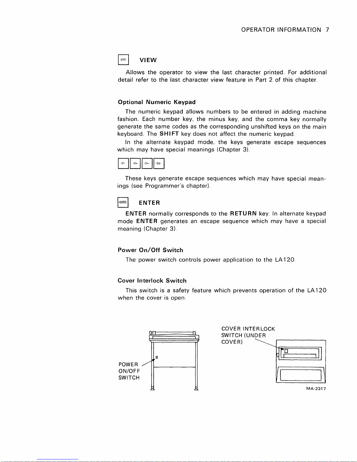
Power
The
Cover
This
when
POWE R
ON/OFF
SWITCH
On/Off
power
switch
Interlock
switch
the
cover is open.
Ul
I
o
/'
~
Switch
controls
power
Switch
is a safety feature
I
1
___
----I
application
which
COVER
SWITCH
COVER)
prevents
INTERLOCK
(UNDER
to
the LA
operation
120.
of
the
LA
120
MA-2317
8 OPERATOR INFORMATION
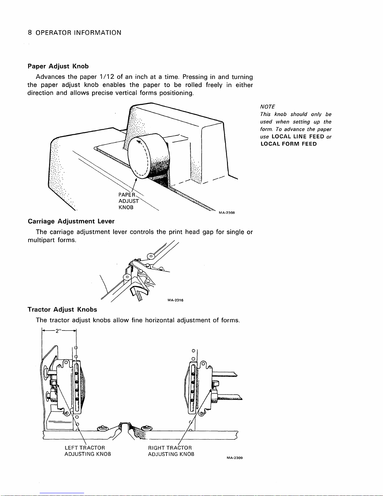
Paper
the paper adjust knob enables the paper
Adjust
Knob
Advances the paper
1/12
of
an
inch
at
a time. Pressing in and turning
to
be rolled freely in either
direction and allows precise vertical forms positioning.
MA-2308
Carriage
Adjustment
Lever
The carriage adjustment lever controls the print head gap for single
multipart
forms.
or
NOTE
This
knob
used
form.
use
LOCAL
LOCAL
should
when
setting
To
advance the
LINE
FORM
only
FEED
FEED
be
up the
paper
or
Tractor
The
Adjust
tractor
adjust knobs
LEFT TRACTOR
ADJUSTING KNOB
Knobs
MA-2316
allow
fine horizontal adjustment
RIGHT TRACTOR
ADJUSTING KNOB
of
forms.
MA-2309
OPERATOR INFORMATION 9
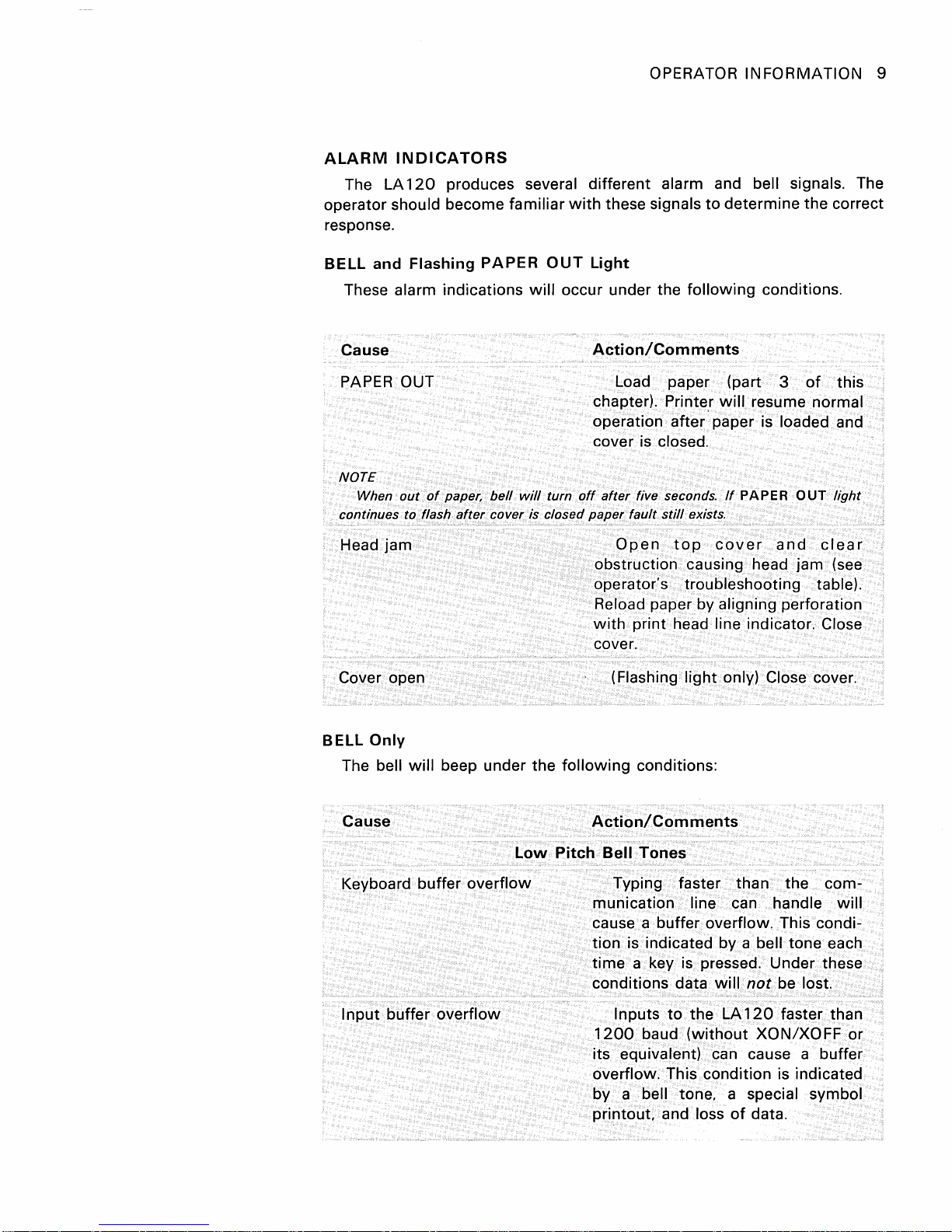
ALARM
The LA
INDICATORS
120
produces several different alarm and bell signals. The
operator should become familiar
response.
BELL
and
Flashing
PAPER
These alarm indications
OUT
will
Cause
PAPER OUT
NOTE
When
out
of
continues to flash
Head
jam
paper,
bell
after
cover is closed
will
turn
with
these signals
to
determine the correct
Light
occur under the
following
conditions.
Action/Comments
Load paper (part 3
chapter). Printer
will
resume normal
operation after paper is loaded and
cover is closed.
off
after
paper
Open
five seconds.
fault
still
top
exists.
cover
If
PAPER
and
obstruction causing head jam (see
operator's troubleshooting table).
Reload paper by aligning perforation
with
print head line indicator. Close
cover.
of
OUT
this
light
clear
Cover open
BELL
Only
The bell
will
Cause
Keyboard buffer
I
nput
buffer
beep under the
Low
overflow
overflow
(Flashing
following
conditions:
light
only) Close cover.
Action/Comments
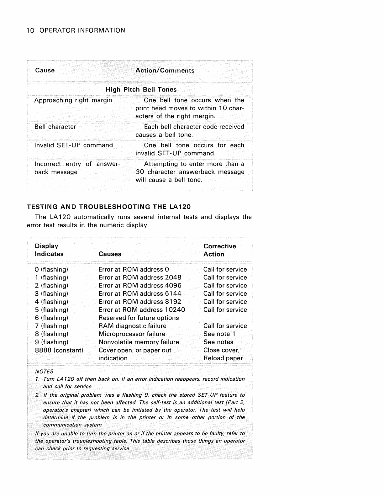
Pitch
Bell
Tones
Typing faster than the communication line can handle
cause a buffer overflow. This condition
is indicated by a bell tone each
time
a key is pressed. Under these
conditions data
Inputs
1200
to
baud
will
the LA
(without
not
be lost.
120
faster than
XON/XOFF
its equivalent) can cause a buffer
overflow. This condition is indicated
by a bell tone. a special symbol
printout. and loss
of
data.
will
or
10
OPERATOR INFORMATION
Cause
High
Approaching right margin ()ne bell
Bell character
Action/Comments
Pitch
Bell
print
head moves
acters
Tones
of
Each'bell cha'racter code received
causes a
tone
occurs
to
within
the right margin.
bell tone.
when
10
Invalid SET-UP command One bell tone occurs for each
invalid SET-UP command.
Incorrect entry
back message
TESTING
The LA
error test
AND
120
results in the numeric display.
Display
Indicates
of
answer-
TROUBLESHOOTING
Attempting
30
character answerback message
will
cause a bell tone.
THE
to
LA120
enter more than a
automatically runs several internal tests and displays the
Corrective
Causes
Action
the
char-
o (flashing)
1 (flashing)
2 (flashing)
3
(flashing)
Error at ROM address 0
Error
at
ROM address
Error at ROM address
Error at ROM address
4 (flashing) Error at ROM address
(flashing)
5
Error at ROM address
2048
4096
6144
8192
10240
for service
Call
Call for service
Call for service
Call for service
Call for service
Call for service
6 (flashing) Reserved for future options
7
(flashing) RAM diagnostic failure Call
for
service
8 (flashing) Microprocessor failure See note 1
(flashing) Nonvolatile
9
8888
(constant)
Coveropen,orpaperout
memory
failure See notes
Close cover,
indication Reload paper
NOTES
1.
Turn LA
and
2.
If
ensure
operator's chapter)
determine
communication system.
If
you are unable to turn the
the operator's troubleshooting table. This table describes those things an operator
can check
120
off
then back
call
for
service.
the original problem was a flashing 9, check the stored SET-UP feature to
that
it
has
not
if
the
problem
prior
to requesting service.
on.
If
an error indication reappears, record indication
been affected. The self-test is an
which
can be
printer
initiated
is in the
on
printer
or
if
by
the operator. The test
or
in some other
the
printer
additional
appears to be faulty, refer to
test
portion
(Part
will
of
2,
help
the
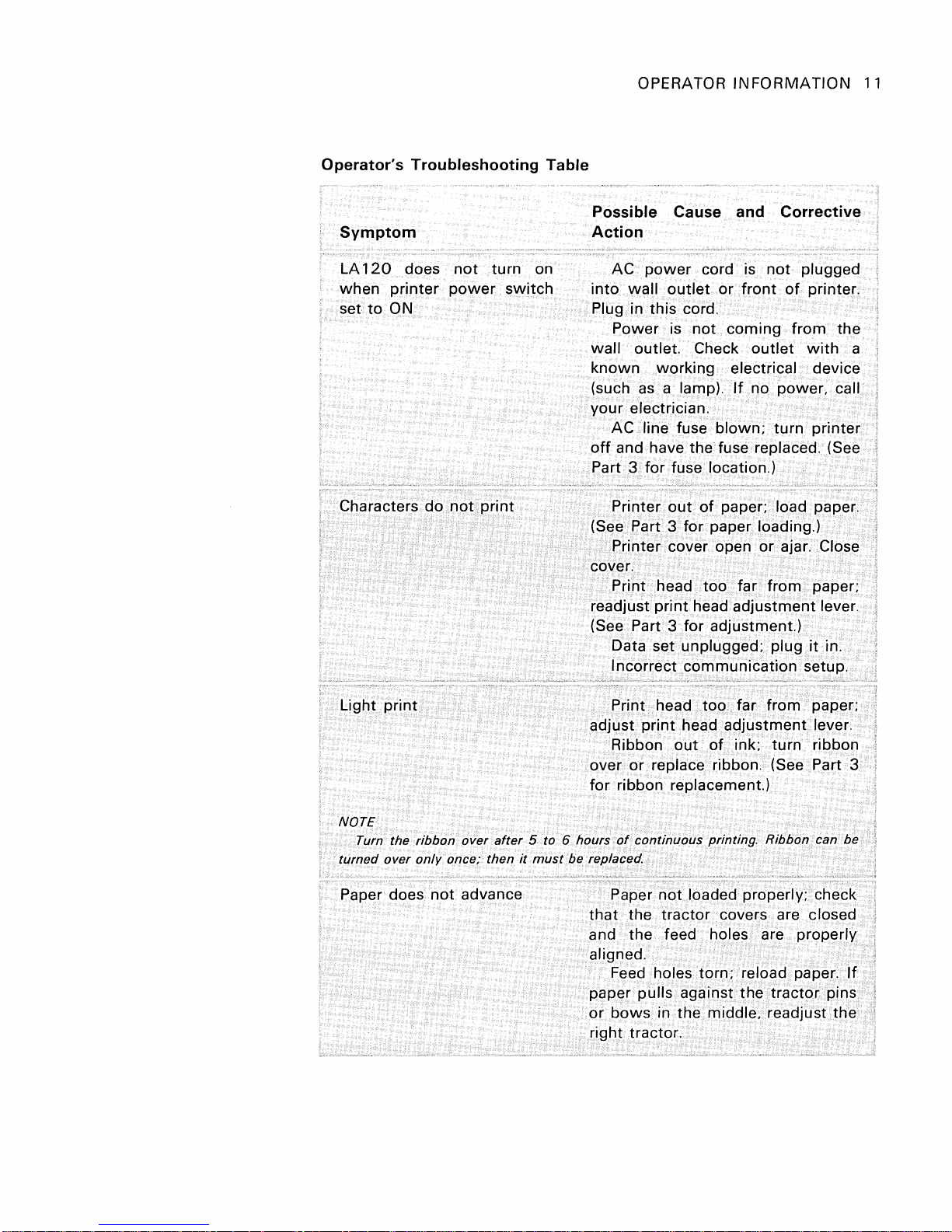
Operator's Troubleshooting Table
Symptom
LA
120
when
set
to
does
printer
ON
not
power
turn on
switch
OPERATOR
INFORMATION
Possible Cause and Corrective
Action
AC
into
power
wall
cord is
outlet
or
not
front
plugged
of
printer.
Plug in this cord.
not
Power is
outlet
wall
known
(such
your
working electrical device
as
a lamp).
electrician.
AC line fuse
off
and have the fuse replaced. (See
coming
Check
If
blown;
from
the
outlet
with
no power, call
turn printer
Part 3 for fuse location.)
11
a
Characters
Light
NOTE
Turn the ribbon over
turned
Paper does
print
over
do
only
not
not
print
after
once; then
advance
5 to 6 hours
it
must
be replaced.
Printer
out
of
paper; load paper.
(See Part 3 for paper loading.)
Printer cover open or ajar.
Close
cover.
Print head
too
far from paper;
readjust print head adjustment lever.
(See Part 3 for
Data set unplugged; plug
adjustment)
it
in.
Incorrect communication setup.
Print head
adjust
Ribbon
or
over
print
replace ribbon. (See Part 3
too
far from paper;
head adjustment lever.
out
of
ink; turn ribbon
for ribbon replacement.)
of
continuous printing. Ribbon can be
Paper
that
the
not
loaded properly: check
tractor
covers are closed
and the feed holes are properly
aligned.
Feed holes torn; reload paper.
paper pulls
or
bows
against
the
tractor
in the middle, readjust the ;
If
pins
right tractor.
1
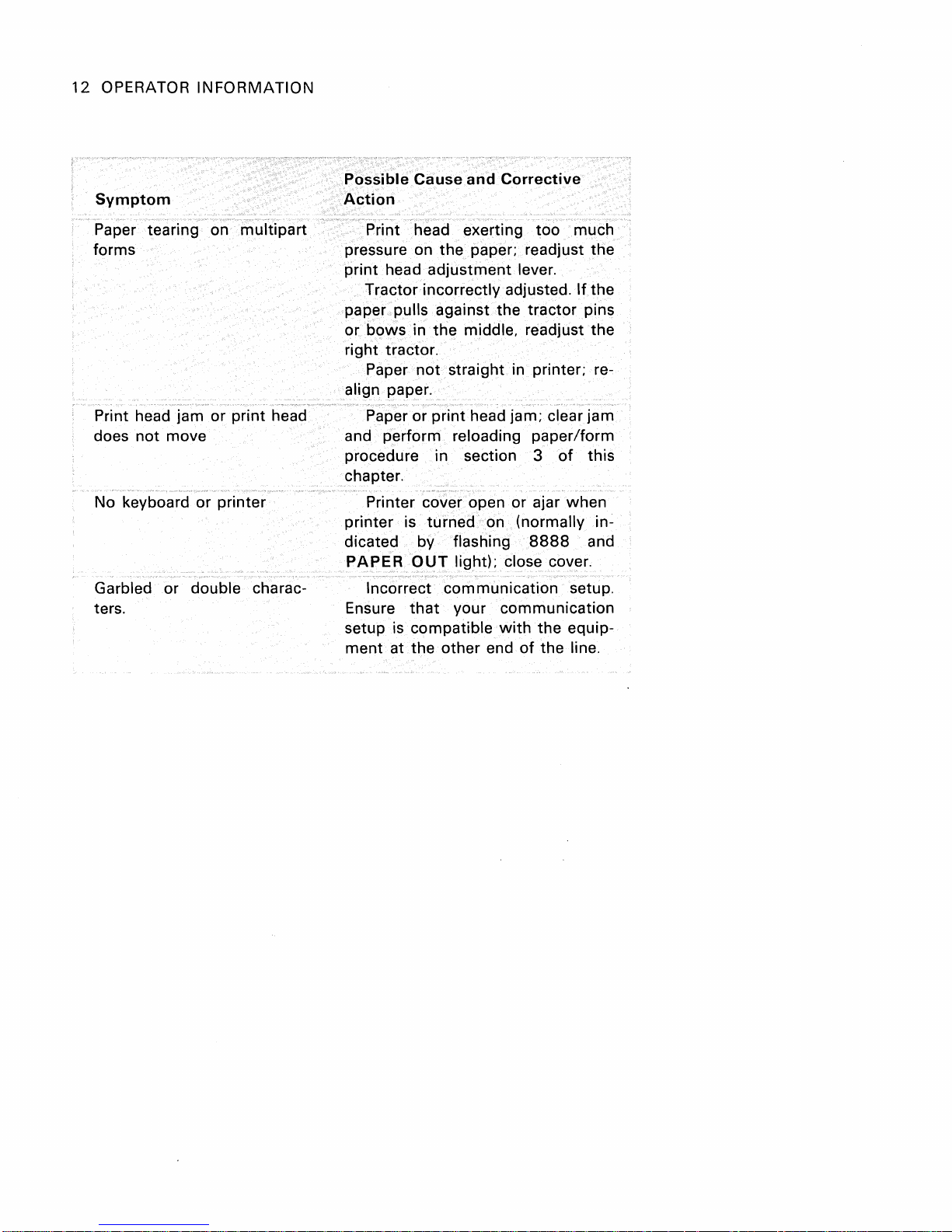
12
OPERATOR
INFORMATION
Symptom
Paper tearing on
forms
Print head jam
or
does not move
No keyboard
Garbled
or
or
double charac-
ters.
multipart
print head
printer
Possible Cause
and
Corrective
Action
Print head exerting
too
much
pressure on the paper; readjust the
print head
Tractor incorrectly adjusted.
adjustment
lever.
If
the
paper pulls against the tractor pins
or
bows
in
the
middle, readjust the
right tractor.
Paper
not
straight in printer; re-
align paper.
Paper or print head jam; clear jam
and perform reloading paper/form
procedure in section 3
of
this
chapter.
Printer cover open or ajar when
printer is turned on (normally indicated by flashing
PAPER
OUT
light); close cover.
8888
and
Incorrect communication setup.
Ensure
setup is compatible
ment
that
your communication
with
at the other end
the equip-
of
the line.

OPERATOR
INFORMATION
13
DECWRITER
LA120
REFERENCE
SET-UP
KEY
I CTRL I and I SET-UP I Locks
NOTES:
1.
LA
120
2.
Do
not
OPERATOR
FUNCTION/COMMENTS
LA
To
exit
Places LA
held
down:
To
exit
must
be
in
set-up
mode
use I SHIFT I unless
CARD
120
in
set-up
set-up
mode
120
in
set-up
SET-UP
set-up
mode
to
set
the
specified.
Sample
LA
120
Operators'
The operators' card is a summary
keys used
operation
mode:
SET-UP
press I SET-UP I
mode
while
light
flashes.
release I SET-UP I
following
features.
light
flashes
I SET-UP I
to
set the features. Once you become
of
the
LA
120,
FORMS
III
IS
KEY
[ill
Card
the card
(CONT)
NOTE: Changing
NOTE:
of
all LA
120
will
be a valuable
FUNCTION/COMMENTS
Horizontal
pitch
(Characters
horizontal
DISPLAY
5
6
7
8
10
12
13
16
Vertical
pitch
Changing
~
12
(Lines per inch)
vertical
2
3
4
6
8
features, plus
familiar
memory
per
CPI
CPI
CPI
CPI
CPI
CPI
CPI
CPI
clears
clears
inch)
left
top
pitch
PITCH
5.00
6.00
6.60
8.25
10.0
12.0
13.2
16.5
pitch
PITCH
2 LPI
3 LPI
4 LPI
6 LPI
8 LPI
12
LPI
and
and
with
right
bottom
the
the
aid.
margins.
margins.
FORMS
KEY
I SHIFT I
[I]
I SHIFT I
m
I SHIFT I
m
I SHIFT I
@]od
[[]
I SHIFT I
[[J
ISHIFTI
ITl
ISHIFTI
II]
and
and m
and
SHIFTI
and
and
and
FUNCTION/COMMENTS
Display
Releasing I
column
Set horizontal tab
Set vertical tab
[I]
Clear horizontal
Clear vertical tab
Clear all horizontal
Clear all vertical tabs
rn
Establish
and
@]
Set
minimum
Set
[[]
@]
ITl
minimum
Set
maximum
Set
maximum
Clear
Clear
Form Length
DISPLAY
th'ru}
168
current
line
SHIFTt-
number
at
at
current
tab
at
top
of
form
column
line
number
column
line
left
and
right
top
and
bottom
NOTE: Changing
bottom
margins
Lines per
number
returns display
current
column
line
at
current
column
current
line
tabs
(TOF)
number
(left margin)
(top
margin)
number
(right margin)
number
(bottom
margins
margins
form
length
and establishes TOF.
form
clears
to
current
margin)
top
and
OPERATOR
KEY
COMFORT
[ill
[]
[EJ
m
COMMUNICATION
KEY
o
FUNCTION/COMMENTS
Bell
volume
o =
Low
Volume
1 = High
Volume
Key click
0=
Off
1 = On
Auto
repeat
0=
Off
1 = On
Last cha racter
o =
1 =
FU
NCTION/COMM
Auto
0=
1 = On
Buffer
view
Manual
Auto
ENTS
answerback
Off
control
o = Small
1 = Large
Printer
character
1 =
2 =
Auto
0=
Off
, = On
Local
0=
, = On
United
United
disconnect
echo
Off
set
States
Kingdom
14
OPERATOR
INFORMATION
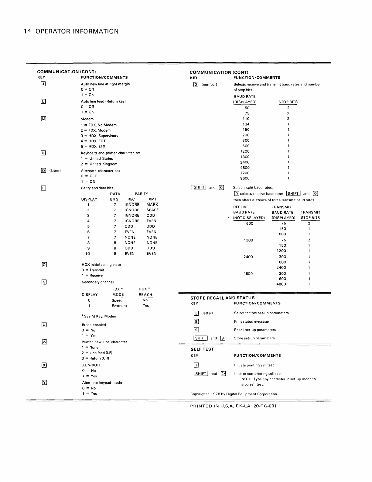
COMMUNICATION
KEY
QJ
[Q]
(letter)
(CO
NT)
FUNCTION/COMMENTS
Auto
new line at right margin
0=
Off
1 = On
Auto
line feed (Return key)
0=
Off
1 = On
Modem
1 = FOX. No
2 = FOX.
3 = HDX. Supervisory
4 = HDX.
5 = HDX.
Keyboard and printer character set
1 = United States
2 = United Kingdom
Alternate character set
o =
1 = ON
Parity
DISPLAY BITS
H
OX
0=
1 = Receive
Secondary channel
DISPLAY
-0--
*
See M Key.
Break enabled
Modem
Modem
EOT
ETX
OFF
and data bits
1 7
2 7
3
4 7
5 7
6 7
7
8 8
9 8
10
initial calling state
Transmit
Modem
DATA
IGNORE
IGNORE SPACE
7
IGNORE ODD
IGNORE
ODD ODD
EVEN
NONE NONE
NONE NONE
ODD
EVEN EVEN
8
FOX
*
MODE
Speed
Restraint
REC
o = No
1 =
Yes
Printer new I ine character
1 = None
= Line feed
2
3 = Return
XON/XOFF
0=
1 =
Alternate keypad mode
0=
= Yes
1
(LF)
(CR)
No
Yes
No
PARITY
HDX *
REV.CH.
---r::ro-
Yes
XMT
MARK
EVEN
EVEN
ODD
COMMUNICATION
KEY
@]
(number)
(CONT)
FUNCTION/COMMENTS
Selects receive and transmit baud rates and number
of
stop bits.
BAUD RATE
(DISPLAYED)
110
134
150
200
300
600
1200
1800
2400
4800
7200
9600
SHIFT I and
I
Selects split baud rates
@]
[QJ
then offers a choice
RECEIVE
BAUD RATE
;
(NOT DISPLAYED)
select s receive baud rate; I
STORERECALLANDSTATUS
KEY
[[]
(letter)
[ID
[[]
ISHIFTI
SELF
TEST
KEY
[!]
I SHIFT I and
Copyright'
and
1978
FUNCTION/COMMENTS
Select factory set-up parameters
Print status message
Recall set-up parameters
Store set-up parameters
[[]
FUNCTION/COMMENTS
Initiate printing self test
Initiate non-printing self test
~
by Digital Equipment Corporation
NOTE: Type any character in set-up mode
stop self test.
STOP BITS
50
----
75 2
of
three transmit baud rates.
TRANSMIT
BAUD
(DISPLAYED) STOP BITS
600
75
150
600
1200
75
150
1200
2400
300
600
2400
4800
300
600
4800
2
2
SH I FT
RATE
I and
@]
TRANSMIT
2
1
2
to
PRINTED
IN
U.S.A.
EK-LA120-RG-001
OPERATOR
INFORMATION
15
Form
settings
matically
LA
120
programmer's
by
loaded
the
can
be
into
computer
chapter).
NOTE
auto-
the
(see
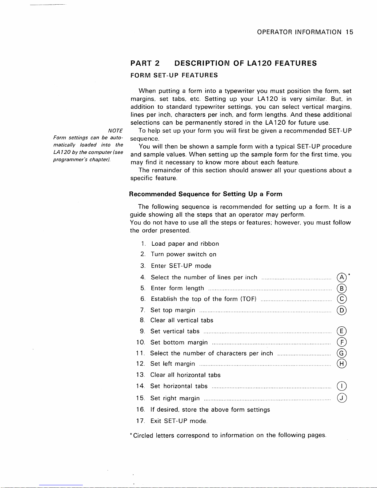
PART
FORM
margins, set tabs, etc.
addition
lines per inch, characters per inch, and
selections
sequence.
and
may
specific feature.
Recommended
guide
You
the order presented.
2
SET-UP
When
help set
To
will
You
sample values.
find
The remainder
The
following
showing
do
not
DESCRIPTION
putting a form
to
standard
can be
up
then be
it
necessary
all
have
OF
FEATURES
into a typewriter
Setting
typewriter
permanently
your
form
shown
When
of
Sequence
sequence is recommended
the
to
use all the steps
a sample form
setting
to
know
this
section should
steps
up
settings, you can select vertical margins,
stored in
you
will
first
up
more
for
Setting
that
an
operator
or
LA120
your
form
the
be given a
with
the
sample
about
answer
Up a
features; however, you
FEATURES
you
must
position
LA
120
is very similar. But. in
lengths.
LA
a typical SET-UP procedure
each feature.
Form
for
may
And
120
for
recommended
form
for
all
your
setting
perform.
the
form, set
these additional
future
questions
up
the
a form.
use.
first
must
SET-UP
time,
about
It
follow
you
a
is a
1.
Load paper and ribbon
2.
Turn
power
3.
Enter SET-UP
4.
Select
5.
Enter
6.
Establish the
7.
Set
top
8.
Clear all vertical tabs
9.
Set vertical tabs ......
10. Set
11.
12.
13.
14. Set horizontal tabs .........................................................................
1
5.
16.
17. Exit
bottom
Select
Set left margin ................................................................................ .
Clear all horizontal tabs
Set
right
If
desired, store
SET-UP mode.
switch
the
number
form
length ........................................................................... .
margin ................................................................................ .
margin ........................................................................ .
the
number
margin
mode
top
the
on
of
lines per inch
of
the
form
(TO
F)
........................................... .
'"
..................................................................... .
of
characters per inch ................................ .
....
....
.........
....
... ...
.....
........
......
......... ....................... 0
above form settings
0*
®
©
@
®
(£)
®
®
CD
* Circled letters correspond
to
information
on
the
following
pages.
16
OPERATOR INFORMATION
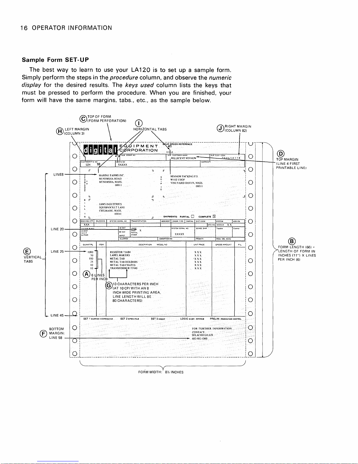
Sample Form
The best
Simply perform the steps
display for the desired results. The keys
SET-UP
way
to learn to
in
use
your LA
120
the procedure column, and observe the
used
must be pressed to perform the procedure.
will have the same margins, tabs., etc.,
form
TOPOFFORM
C
(FORM
®
VERTICAL
TABS
©
®
LEFT
MARGIN
ICOLUM::~~
~~DmDDmnl~su'O'O"NO
O
::~
'reus
LI N
LI NE 20
LINE
o
E8
--i----i---
o
o
o
o
-t--rt-'u.I:'O.ilJEST
o
()
25
--1--'--
o
o
o
o
!r'-OO-"N~G~CTR~'I-S-AL'-S"-AN~I--s"-TE-M-MO-O'-LN-O-r------~~-lr"-'EE-"[-"rO-'O-E'-"-.E~I-·A-AT-'AL~------'------TTA-OO-O-N-':,
::g,';.,
l~a~u.~NT_'~~~_+------------~--~------------~--------_+--------+_---i:"
PERFORATION)
____
i~~~~I~~~brl~~
~~.O
r
---
c
i
~
L
9 r
T
o L J SH'PMENTS, PARTIAL 0 COMPLETE
XXX J
.......
1000'"
100
®';:
\
~
______
~
___
~~~~j:"'''~'''''
NO,O/
"'-----~::.:....-H
50
~5
10
IN'S
PE~ INC~
I
MARINE FARMS INC.
MI·.NFMSIlA ROAD
MFNIMSIIA.
~;~
JAWS
INOLISTRII:S
SQlIlBNOCKET LANI' ! 0
rtllLMARK.
~o~~~
RESISTOR
LABEL
~
METAL TAB IX X X
METALTABIIOLDERS
MI'TAlTABCRATrS
f"":m'T''"w
fG\10
CHARACTERS
~(AT
INCH WIDE
LINE
80
CHARACTERS)
CD
HORIZONTAL
______________
~~;~X
..
~L
If:::
:::.::.:::::.:..;--L_~~_~~~_L
I
ALLOWEO
MAKlRS
10
______
73684 X X X
WITH
AN
PRINTING
WILL
PER
CPI
LENGTH
is
to set up a sample form.
column lists the keys
When
as
you are finished, your
the sample below.
TABS
_______________________
8
BE
INCH
Is""ueuswM'.".,
~~M~IL~L1~CE~N~T~M~IN~NO~W~~;l====~~'~4~1~1~4~'~~
I
r
I
MINNOW PACKIN(;
~:~(;~~~~·IIAVIN.
J
,
--.
__
----L_X_XX_X_X
I EXEMPTtONNO
AREA,
..
__
J""ANTY
CO
MASS.
00011 !
___
+-
___ +-___
X X X
XXX
XXX
m : 0
numeric
that
RIGHT
fJ'
~(COLUMN
MARGIN
82)
--rV--r\
Jsu.eu"e~o~"
(R]
IMFQ
MO MOOULE X X
! 0 @
Ii
' 0
'1
i
! 0
J:,:
0
:
I
0
TEo.m"
!
I--I
__
-4i:
0
()
:i:
0
__
1-
__
-LTOPMARGIN
(LINE
4 FI RST
PRINTABLE
®
FORM
LENGTH
LENGTH OF FORM IN
(11")
INCHES
PER
INCH (6)
LINf:)
(66) =
X LINES
o
o
LINE
45
®
-W-; ___
BOTTOM
MARGIN:
LINE
o
58
-I-;...,-f------------------------_
o : 602-602-1000 i 0
0:
____ L ____________________________________________________________________________________
....l-
__
--L-
_______________________
I I
I I
~~--------------------
SET 2
OPEN
FILE
FORM
SET 3
CIitIOIT
. y
WIDTH:
I--
lOGIC
_______
CUlT.
FOR
CONTACT:
SELArtlll
-'--
INVOICI! PRELIM.
____
'filOOUCTION
FURTHER INFORMATION
GILLIS
--'-
CONTIitOL
__
_
o
::,'
0
10
L
____
I )
I
__
L/
~-------------------)
8Y,
INCHES
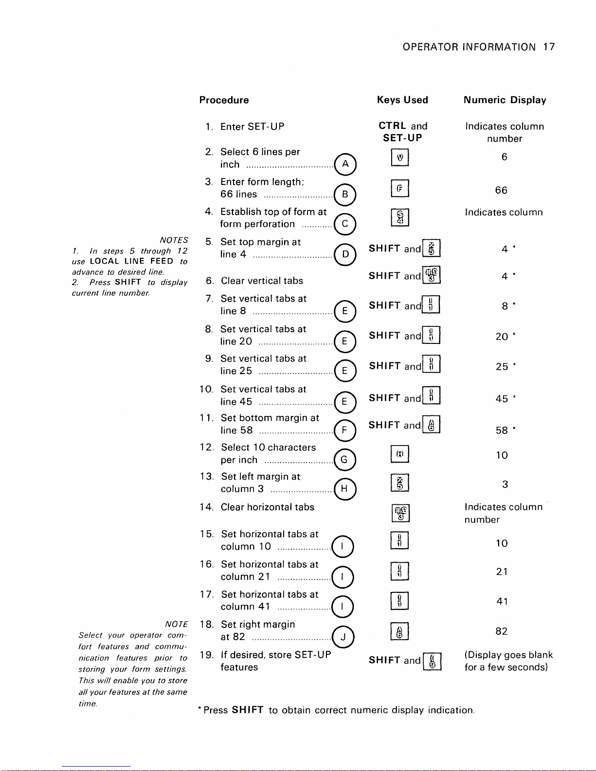
Procedure
Keys
OPERATOR
Used
INFORMATION
Numeric
Display
17
1.
I n
use
LOCAL
advance
2.
Press
current
NOTES
steps 5 through
LI
N E FEE D
to
line
desired
SHIFT
number.
line.
to
display
1.
Enter SET-UP
2. Select 6 lines per
inch .................
3.
Enter
form
66
lines ........................... 0
4. Establish
form perforation ............ 0
5.
Set
top
12
to
line 4 ............................... 0
6.
Clear vertical tabs
7.
Set vertical tabs at
margin
Iine8·······························0
8.
Set vertical tabs
line20
9.
Set vertical tabs at
............................. 0
Iine25·····························0
10. Set vertical tabs at
line45·····························0
11. Set
line
bottom
58
............................. 0
length;
top
margin
of
···
....
form
at
at
···.·
at
.....
at
0
CTRL
SET-UP
[!]
[I]
[]]
SHIFT
SHIFT
SHI
FT
SHIFT
SHIFT
SHIFT
SHIFT
and
andl
~
Indicates
number
66
Indicates
I
andl~l
and[]]
and[]]
andOJ
andOJ
and[]]
20
45
58
column
6
column
4 *
4 *
8 *
25
*
*
*
*
Select
fort
features
nication
storing
This
will
all
your
time.
your
operator
features
your
form
enable
features
and
you
at
NOTE
com-
commuprior
settings.
to
store
the
same
12. Select
10
characters
per inch ........................... 0
13. Set
left
margin
column 3 ........................ 0
14. Clear horizontal tabs
Set horizontal tabs at
15.
column
16.
Set horizontal tabs at
column
17.
Set horizontal tabs at
column
18.
Set
right
10
21
41
margin
at82·······························0
If
to
19.
* Press
desired, store SET-UP
features
SH
I FT
to
at
....................
(~)
..................... 0
..................... 0
obtain correct
~
[]J
Indicates
~
OJ
number
rn
OJ
[]]
SHIFTandl~1
numeric
display indication.
(Display goes blank
for a
10
3
10
21
41
82
few
column
seconds)
18
OPERATOR
INFORMATION
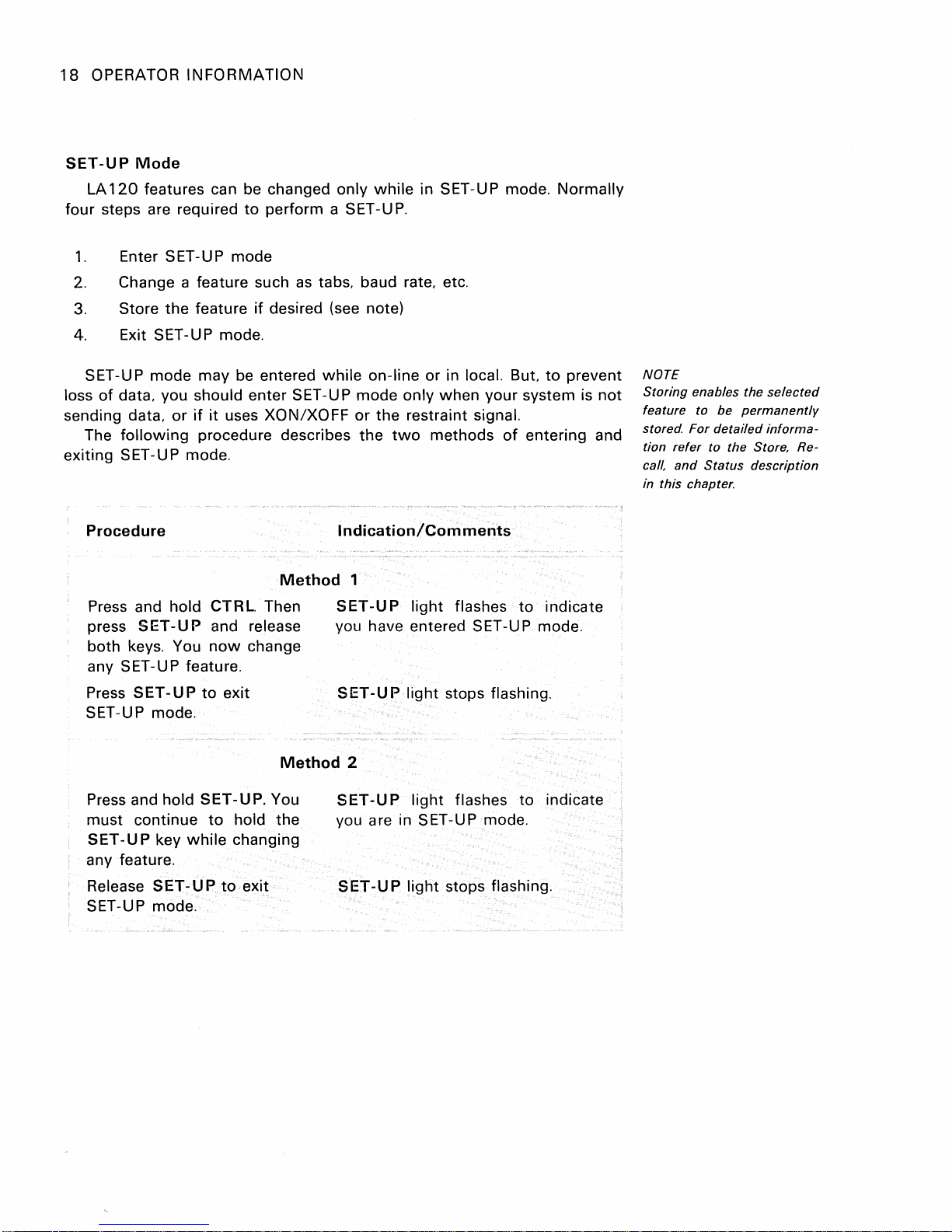
SET-UP
LA
Mode
120
features can be changed only
four steps are required
1.
Enter SET-UP mode
2.
Change a feature such
3.
Store
the
feature
4. Exit
SET
loss
of
sending data.
The
exiting
SET-UP mode.
-UP mode may be entered
data. you should enter
or
if
it
uses XON/XOFF
following
procedure describes
SET-UP mode.
Procedure
Press and hold CTRL. Then
press
SET-UP
both keys. You
any SET-U
Press
SET-UP
and release you have entered SET-UP mode.
now
P feature.
to
exit
SET-UP mode.
to
perform a SET-U
as
tabs. baud rate. etc.
if
desired (see note)
while
SET
-U P mode only when your system is
Indication/Comments
Method
SET
change
SET-UP
while
in SET-UP mode. Normally
P.
on-line or in local. But.
or
the restraint signal.
the
two
methods
1
-U P
light
flashes
light stops flashing.
to
of
entering and
to
indicate
prevent
not
NOTE
Storing
feature
stored.
tion
call,
in this chapter.
enables the
to
be
For
detailed
refer
to the Store. Re-
and
Status
selected
permanently
informa-
description
Method
Press and hold SET-UP. You
must continue
SET-UP
key
to
while
hold the
changing
any feature.
Release
SET-UP
to
exit
SET-UP mode.
2
SET
-U P
you are in
SET
-U P
light
flashes to indicate
SET-UP mode.
light
stops flashing.
OPERATOR
INFORMATION
19
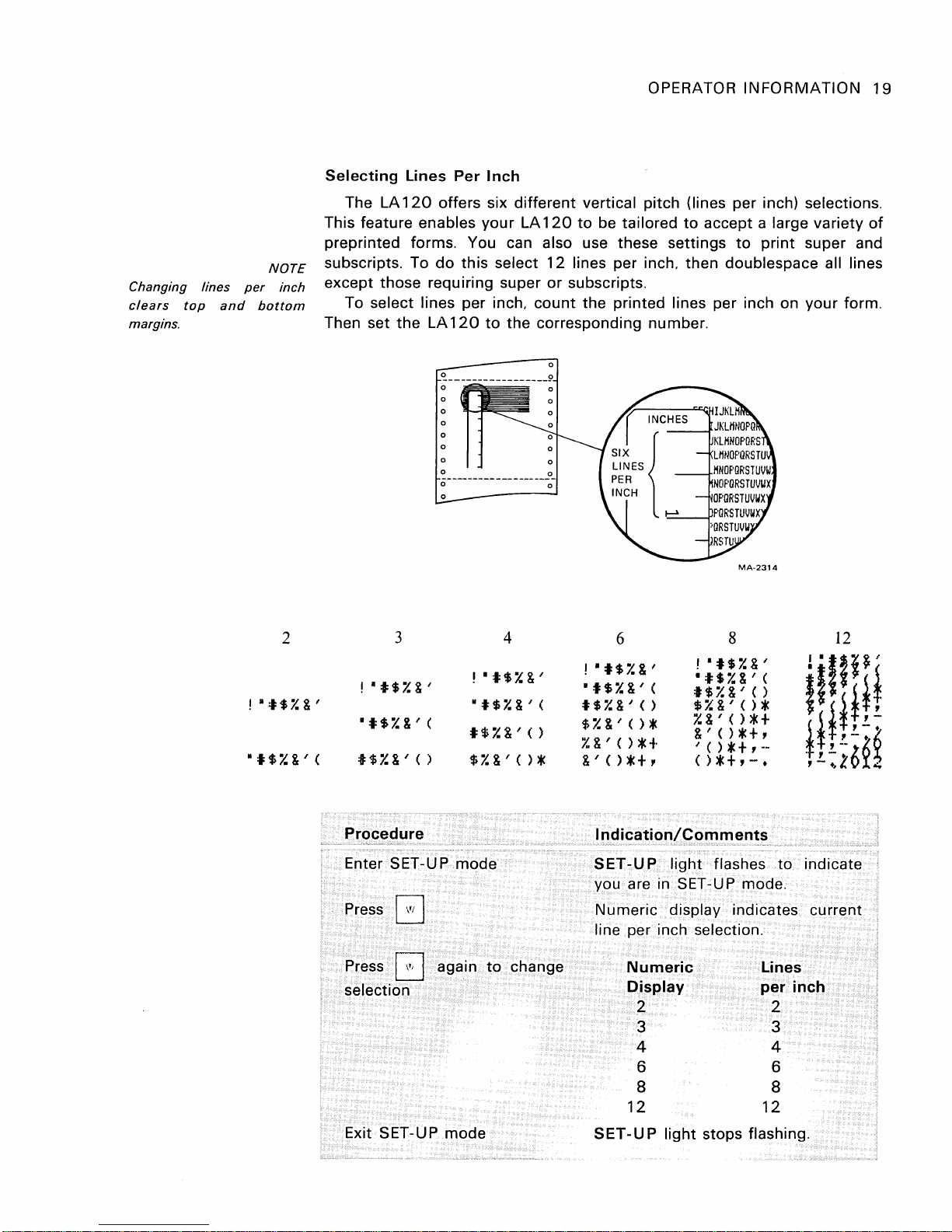
Changing
clears
margins.
top
lines
and
per
bottom
NOTE
inch
Selecting
The LA
This feature enables
preprinted forms. You can also use these settings
subscripts. To
except those requiring super
To
Then set
Lines
120
select lines per inch,
the
Per
offers six
do
this
LA
120
Inch
your
select
to
the
different
vertical pitch (lines per inch) selections.
LA
120
to
be tailored
12
lines per inch, then doublespace all lines
or
subscripts.
count
the
printed lines per inch on
corresponding number.
to
accept a large variety
to
MA-2314
print
of
super and
your
form.
2
!
11:1:$7.&'
1:1:$7.&'(
3
(
, 1:1:$7.&'
It$7.&"(
I$i.:&'()
$y'&'()*
mode
!
11:1:$7.&'
11$1.&'
t$i.:&'()
Procedure
Enter SET-UP
Press G
Press 0 again
selection
Exit SET-UP mode
4
to
change
6
!
11$7.&'
1:1:$7.&'(
t$7.&"()
$i.:&"()*
%&'()*+
&'()*+,
Indication/Comments
SET-UP
you are in SET-UP mode.
Numeric
line per inch selection.
light
display indicates current
Numeric
Display
2
8
'11$7.&'
1:1:$7.&' (
t$7.&"()
$y'&"()*
I.&'()*+
&'()*+,
"()*+,--
()*+,-.
flashes
3
4
6
8
12
SET-UP
light
stops flashing.
12
!
'liP'
I'{!!H
*i!:6£~
,
.. 1 .:..
to
indicate
Lines
per
inch
2
3
4
6
8
12
 Loading...