

Digital Equipment InfoServer 150 Installation And Owner's Manual

InfoServer150
InstallationandOwner’sGuide
Order Number: EK–INFSV–OM–001
This manual describes how to install, test, operate, and maintain the
InfoServer 150 system.
Digital Equipment Corporation
Maynard, Massachussets

October 1991
The information in this document is subject to change without notice and should not be
construed as a commitment by Digital Equipment Corporation. Digital Equipment Corporation
assumes no responsibility for any errors that may appear in this document.
The software described in this document is furnished under a license and may be used or copied
only in accordance with the terms of such license.
No responsibility is assumed for the use or reliability of software on equipment that is not
supplied by Digital Equipment Corporation or its affiliated companies.
© Digital Equipment Corporation 1991.
All Rights Reserved.
The following are trademarks of Digital Equipment Corporation: DEC, DECnet, DECconnect,
DIGITAL, ULTRIX, VAX, VAXserver, VAXstation, VMS, VT, and the Digital logo.
The following are third-party trademarks:
Intel is a registered trademark of Intel Corporation.
MS–DOS is a registered trademark of Microsoft Corporation.
PostScript is a registered trademark of Adobe Systems Incorporated.
Xerox is a registered trademark of Xerox Corporation.
ZK5900
This document is available on CDROM.
This document was prepared using VAX DOCUMENT, Version 2.0.

Contents
Preface ..................................................... vii
1 InfoServer 150 System Overview
1.1 System Highlights . ................................... 1–2
1.2 Storage Devices . . . ................................... 1–3
1.2.1 Internal RZ Hard Disk . . . ........................... 1–3
1.2.2 RRD42 Compact Disc Drive .......................... 1–3
1.3 Console Terminal . . ................................... 1–4
2 Installing Your System
2.1 Choosing the Right Location for the System ................ 2–1
2.2 Unpacking and Inspecting System Components .............. 2–2
2.3 Connecting System Components ......................... 2–4
2.3.1 Identify the System Unit Ports and Connectors . .......... 2–4
2.3.2 Install the SCSI Terminators ......................... 2–5
2.3.3 Install the Connector Covers ......................... 2–5
2.3.4 Attach the Ethernet Terminators . . . ................... 2–6
2.3.5 Connect the System Unit Power Cord .................. 2–9
2.3.6 Connect a Console Terminal.......................... 2–10
2.3.7 Connect External Expansion Boxes . ................... 2–11
2.4 Starting the System ................................... 2–11
2.5 Loading a Compact Disc................................ 2–12
2.6 Unoading a Compact Disc . . . ........................... 2–16
2.7 Connecting the System to a Network . . . ................... 2–17
2.8 Turning Off the System ................................ 2–18
2.9 Bootstrapping the System . . . ........................... 2–18
2.9.1 Bootstrapping the System Automatically Without a
Console ......................................... 2–18
2.9.2 Starting the System with a Console, Only If Necessary . . . . . 2–18
2.9.3 Recovering from Bootstrap Failures . ................... 2–19
iii

3 Expanding Your System
3.1 Guidelines for Connecting Expansion Boxes ................ 3–1
3.2 Preparing Your System for an Expansion Box ............... 3–2
3.3 Unpacking an Expansion Box . . . ........................ 3–3
3.4 Connecting One Expansion Box . . ........................ 3–3
3.5 Connecting Two Expansion Boxes ........................ 3–5
3.6 RRD42 Compact Disc Expansion Box...................... 3–6
3.6.1 Verifying the SCSI ID Number on the RRD42 Expansion
Box............................................. 3–7
3.6.2 Resetting the SCSI ID on the Second RRD42 Expansion
Box............................................. 3–7
3.7 Preventive Maintenance ................................ 3–8
4 Connecting to a Network
4.1 Connecting to a ThinWire Ethernet Network ................ 4–1
4.1.1 Check the Network Select Button ..................... 4–1
4.1.2 Verify Your ThinWire Ethernet Network Installation....... 4–2
4.1.3 Connect Your System to ThinWire Ethernet Cable . ....... 4–3
4.2 Creating a ThinWire Ethernet Work Group . ................ 4–4
4.2.1 Connecting Your System to a DECconnect Faceplate ....... 4–5
4.2.2 Troubleshooting the ThinWire Segment . ................ 4–6
4.3 Connecting to a Standard Ethernet Network ................ 4–9
4.3.1 Check the Network Select Button ..................... 4–9
4.3.2 Verify Your Standard Ethernet Network Installation ....... 4–9
4.3.3 Connect a Transceiver Cable to Your System ............. 4–10
4.3.4 Troubleshooting the Standard Ethernet Connection. ....... 4–10
5 Solving Problems
5.1 Checking Cable Connections ............................ 5–1
5.2 Using the Troubleshooting Table . ........................ 5–2
5.3 Interpreting Power-Up Error Messages .................... 5–5
5.4 Running Self-Tests .................................... 5–7
5.5 Displaying System Configuration Information ............... 5–8
5.6 Displaying Device Information . . . ........................ 5–9
5.7 Using the System Exerciser ............................. 5–10
5.8 Running Test Utilities for Expansion Boxes . ................ 5–12
5.9 Restarting the System after Running Tests . ................ 5–12
5.10 Reestablishing Console Parameters ....................... 5–12
5.11 Service Information . . . ................................ 5–13
5.12 Command Summary . . ................................ 5–13
iv

A SCSI ID Numbers
A.1 SCSI ID Default Settings ............................... A–1
A.2 Determining SCSI ID Numbers .......................... A–2
A.3 Setting RRD42 ID Numbers. . ........................... A–3
B System Specifications
Glossary
Index
Figures
1–1 InfoServer 150 System Enclosure. . . ................... 1–1
1–2 Front Panel of Embedded RRD42 Drive................. 1–2
2–1 InfoServer 150 System Components. ................... 2–3
2–2 Ports and Connectors ............................... 2–4
2–3 Rear Panel with SCSI Terminators Installed . . . .......... 2–5
2–4 Connector Covers .................................. 2–6
2–5 Attaching T-connectors. . . ........................... 2–7
2–6 Connecting the Power Cord .......................... 2–9
2–7 Connecting the Console Terminal Cable ................. 2–10
2–8 Opening the Caddy ................................ 2–13
2–9 Loading the Disc .................................. 2–14
2–10 Loading the Caddy in the Drive ....................... 2–15
2–11 Ejecting the Caddy from the Drive. . ................... 2–16
2–12 Front Panel of RRD42 Drive ......................... 2–17
3–1 Removing SCSI Terminator .......................... 3–2
3–2 Connecting One RRD42 Expansion Box ................. 3–4
3–3 Connecting Two RRD42 Expansion Boxes ............... 3–6
3–4 RRD42 Real Panel ................................. 3–7
4–1 Position of Network Select Button and Ethernet Lights . . . . 4–2
4–2 Position of Halt Button . . ........................... 4–3
4–3 Attaching T-Connector with Cable Segment to BNC
Connector ........................................ 4–4
4–4 Connecting to DECconnect Faceplate................... 4–6
4–5 Disconnecting T-connector ........................... 4–8
v

4–6 Securing Standard Ethernet Connector . ................ 4–10
Tables
1 Related Documents ................................ viii
3–1 SCSI Devices Self-Test Status Codes . . . ................ 3–8
5–1 Troubleshooting Basic System Problems ................ 5–3
5–2 Power-Up and Self-Test Display Identifiers .............. 5–6
5–3 Definition of Mnemonics ............................ 5–9
5–4 SET Command Summary............................ 5–13
5–5 TEST Command Summary . . ........................ 5–14
5–6 SHOW Command Summary. . ........................ 5–15
A–1 SCSI ID numbers for InfoServer 150 System ............. A–2
vi

Document Purpose
This document describes how to install, test, operate, and maintain the
InfoServer 150 system. This system is a general-purpose disk storage server
that quickly and efficiently transfers data between disks connected to the
server and remote network client systems.
For information on session management and software commands, see the
InfoServer System Operations Guide.
Intended Audience
This document addresses persons responsible for installing, operating, or
maintaining the InfoServer 150 system.
Document Structure
This document is organized as follows:
• Chapter 1 provides an overview of the InfoServer 150 system.
• Chapter 2 provides instructions for installing new InfoServer 150 systems.
• Chapter 3 provides information on installing and using add-on storage
devices and software-loading devices such as compact disc drives.
Preface
• Chapter 4 explains how to connect your system to a ThinWire Ethernet
or standard Ethernet network. The chapter also explains how to connect
systems into a simple ThinWire work group.
• Chapter 5 provides troubleshooting information.
Appendixes provide information on the following topics:
• Setting SCSI ID numbers on drives for custom configurations
• System specifications
The glossary explains technical terms used in the document.
vii

Related Documents
Consult your Digital sales representative for information on obtaining the
documents listed in Table 1.
Table 1 Related Documents
Titles Order Number
InfoServer Documentation
InfoServer System Operations Guide AA–PJXJA–TE
InfoServer 100 Installation and Owner’s Guide EK–DIS1K–IN
Client Documentation
VMS LAD Control Program Manual AA–PD1LB–TE
SCSI Device Documentation
RRD40 Disc Drive Owner’s Manual EK–RRD40–OM
RRD42 Disc Drive Owner’s Manual EK–RRD42–OM
TK50Z User’s Guide EK–OTK50–UG
DECconnect System Documentation
DECconnect System General Description EK–DECSY–GD
DECconnect System Requirements Evaluation Workbook EK–DECSY–EG
DECconnect System Installation and Verification Guide EK–DECSY–VG
DECconnect System Standalone ThinWire Networks:
Planning and Installation Guide
DECconnect System Planning and Configuration Guide EK–DECSY–CG
viii
EK–DECSY–TG

Conventions
The following conventions are used in this document:
Return
lO
red ink Red ink indicates information that you must enter from the
boldface text Boldface text represents the introduction of a new term
italic text Italic text represents information that can vary. (for
UPPERCASE TEXT Uppercase letters indicate that you must enter a command
numbers Unless otherwise noted, all numbers in the text are assumed
A key name is shown enclosed to indicate that you press a
key on the keyboard.
The on/off power switch on equipment. You press | to turn
power on, or O to turn power off.
keyboard or a screen object that you must choose or click on.
For online versions of the book, user input is shown in bold.
defined the glossary or a phrase that is emphasized in text.
Boldface text is also used to show user input in online
versions of the book.
example, device).
(for example, enter TEST 50).
to be decimal. Nondecimal radixes—binary, octal, or
hexadecimal—are explicitly indicated.
ix

1
InfoServer 150 System Overview
The InfoServer 150 system is a general-purpose disk storage server that
quickly and efficiently transfers data between disks connected to the server
and remote network client systems. It provides users with a low-cost data
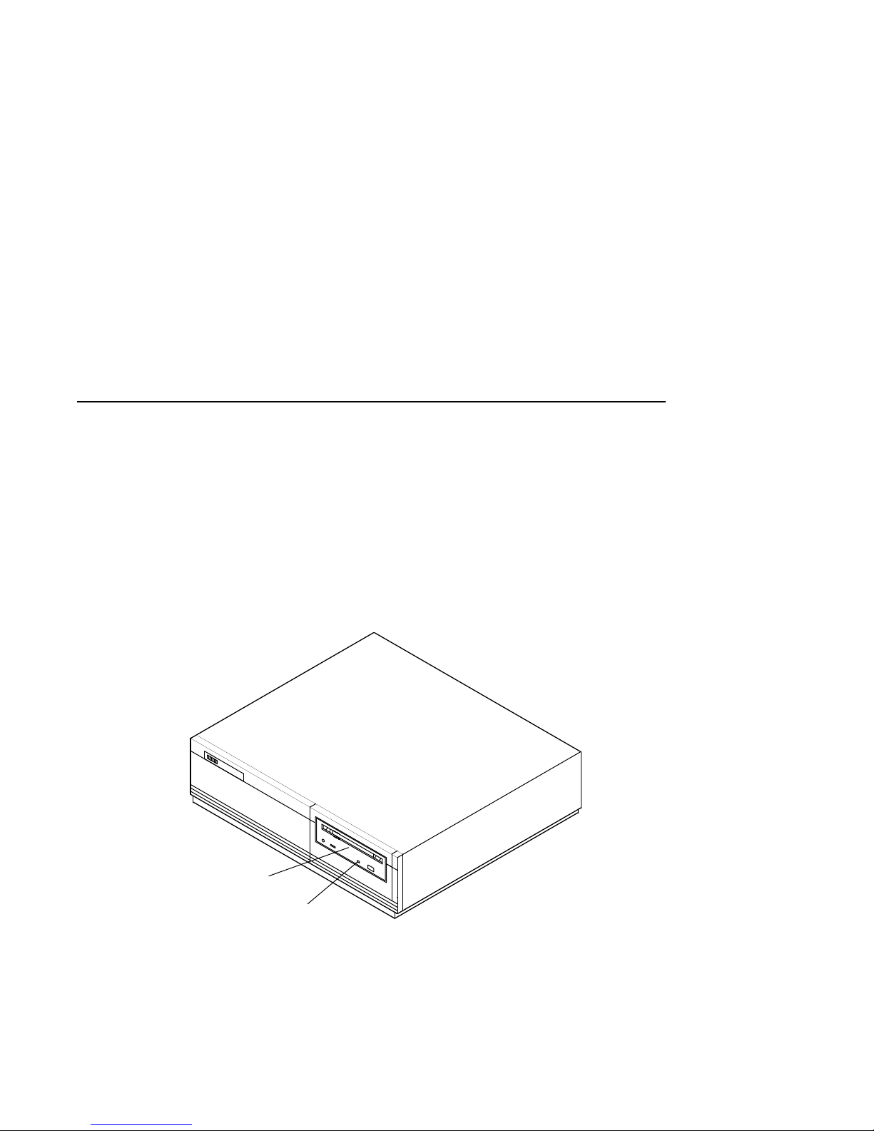
sharing capability that is flexible and easy to manage. Figure 1–1 shows the
InfoServer 150 system enclosure.
Figure 1–1 InfoServer 150 System Enclosure
Compact
Disc Drive
Drive Labels
The InfoServer system can support many diverse applications. For
example, VMS and other client systems can share software distribution and
documentation on compact discs connected to the server. Some VAX systems
can use the server to load their bootstrap program and then to perform a
VMS operating system installation from a compact disc in the server.
MKV-X3105-91
1–1
InfoServer 150 System Overview
1.1 System Highlights
1.1 System Highlights
Your InfoServer 150 system has many special features:
• Memory
The system comes with 4 MB of internal random access memory (RAM).
• ThinWire and standard Ethernet connectability
You can connect the InfoServer system to standard Ethernet or ThinWire
Ethernet work groups and networks but not to both types at the same
time.
• RRD42 compact disc drive
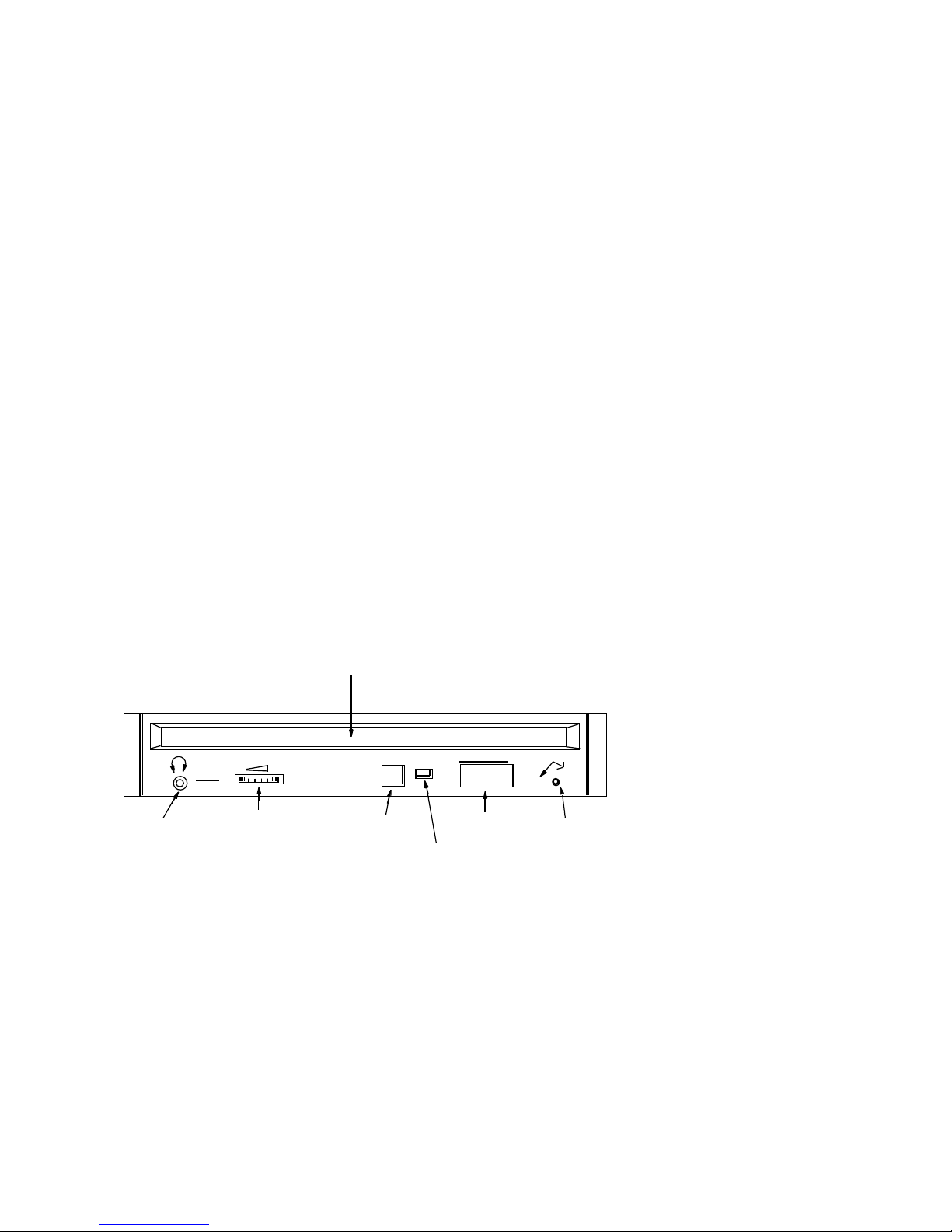
One RRD42 compact disc drive is mounted at the front on the server.
Figure 1–2 shows the drive’s front panel.
Figure 1–2 Front Panel of Embedded RRD42 Drive
CADDY INSERTION
SLOT
HEADPHONE
JACK
HEADPHONE
LEVEL
CONTROL
• Internal hard disk drive
The InfoServer 150 system includes one internal disk drive. This drive
stores server configuration information. The drive can also be served to
client nodes as writable storage. The InfoServer 150 system configuration
comes with an RZ23L drive; the InfoServer 150VXT system configuration
comes with an RZ24 drive.
• Self-sensing power supply
The system power supply accepts power inputs in the ranges of 100 Vac to
120 Vac and 200 Vac to 240 Vac, at 50 or 60 Hertz. A selection switch is
not needed.
1–2
DIMPLE FOR
ID NUMBER
LABEL
BUSY
INDICATOR
EJECT
BUTTON
EMERGENCY
EJECT
HOLE
SHR−XR0062−90

• Communication ports
A single DEC-423 asynchronous port (with MMJ connector for VT series
terminals) is provided as standard. You can use this port to connect a
terminal to the server to establish a local server management session.
(See Section 2.3.6 and the InfoServer System Operations Guide for more
information). This port is preset to run at 9600 baud, so any terminal
connected to this port must be set at 9600 baud.
• SCSI connectability
The small computer systems interconnect (SCSI) is an industry standard
for connecting mass storage devices.
• Add-on storage devices
You can purchase external expansion boxes to provide added storage
capability. These external boxes must be qualified by Digital in order to
meet the system requirements. You can connect up to 12 external drives to
the server, provided you observe SCSI bus length guidelines.
1.2 Storage Devices
The InfoServer 150 system uses the following internal storage devices:
• RZ23L hard disk (InfoServer 150 system configuration)
InfoServer 150 System Overview
1.1 System Highlights
• RZ24 hard disk (InfoServer 150VXT system configuration)
• RRD42 compact disc drive
Figure 1–1 shows the location of the RRD42 compact disk drive in the system
enclosure.
1.2.1 Internal RZ Hard Disk
The server has one internal RZ drive. After the initial system bootstrap, the
server uses this drive as its primary bootstrap device. For the initial bootstrap,
the server uses the software compact disc supplied with the system.
The server also uses the RZ drive to save server characteristics and network
configuration information for use at subsequent server bootstraps.
1.2.2 RRD42 Compact Disc Drive
A compact disc is an optical, read-only storage media. The InfoServer 150
system comes with one RRD42 compact disc drive. The system can bootstrap
from compact disc, although the internal RZ hard disk drive is the primary
bootstrap device.
You can use the RRD42 drive for many purposes, such as software installation
and database storage.
1–3

InfoServer 150 System Overview
1.2 Storage Devices
You can increase the number of compact disc drives on your server by using
RRD42 expansion boxes. See Chapter 3 for information about these add-on
devices.
1.3 Console Terminal
The InfoServer 150 system is designed to require a minimum amount of system
management. You normally issue server commands by using a LAT terminal
session created to the InfoServer 150 system from a terminal server. In the
rare event that your server has problems communicating with client systems,
you can connect a terminal to MMJ port 1 on the back of the system unit (see
Section 2.3.6) and follow instructions in Chapter 5 to troubleshoot the problem.
The recommended console terminal is a VT300 series terminal.
1–4

Installing Your System
Setting up your InfoServer 150 system is easy. This chapter provides
step-by-step instructions on how to perform the following operations:
• Choose the right location for the system
• Unpack and inspect system components
• Connect system components
• Start the system
• Load and unload compact discs
• Connect the system to the network
• Turn off the system
• Bootstrap the system
• Recover from bootstrap failures
2.1 Choosing the Right Location for the System
2
Use the following checklist to keep your system operating at its best:
• Carefully read all installation instructions before you turn on the power.
• Keep the air well circulated to prevent excess heat and dust from
accumulating.
• Keep your equipment away from heaters, photocopiers, direct sunlight, and
abrasive particles.
• Before you set up your system, select a surface that is large enough to hold
the system unit. Your desk or work table is a good choice.
• Keep the area clean. Do not place food or liquid on or near your equipment,
and do not place your system unit directly on the floor. Dust and dirt will
damage the system components.
2–1

Installing Your System
2.1 Choosing the Right Location for the System
• Keep air vents clear on each side of the system unit for proper ventilation.
Do not place the system unit on its side. Blocking the air vents can cause
the system unit to overheat.
• Connect your system to a dedicated grounded circuit.
If you have several pieces of equipment that need to be plugged into a
power outlet, use a grounded power strip. Many power strips come with an
on/off switch and a surge protector.
Do not exceed the current capacity of the circuit.
• To avoid damaging equipment that has been moved inside from a cold
environment, let the equipment warm to room temperature before you turn
it on.
2.2 Unpacking and Inspecting System Components
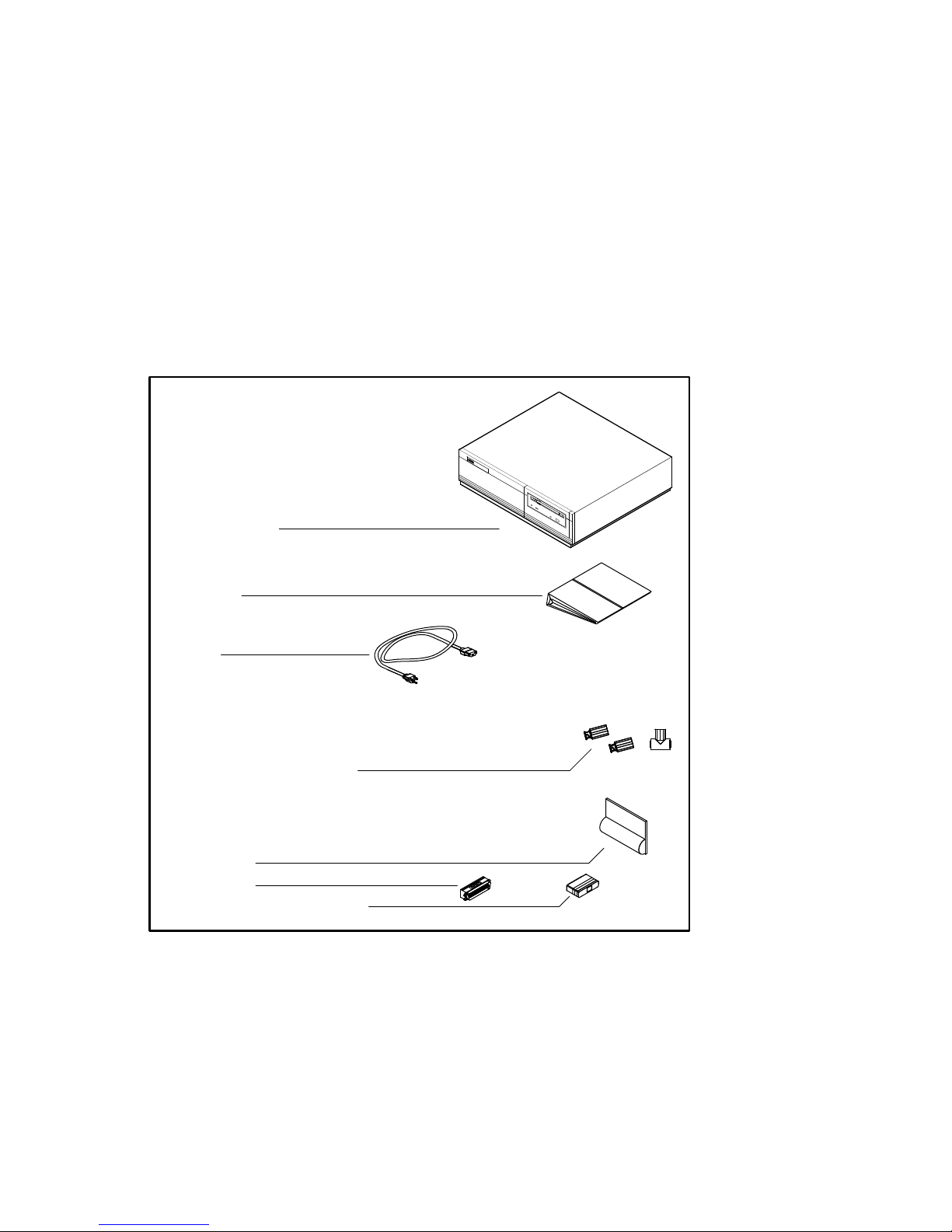
The InfoServer 150 system is shipped in two boxes, one for hardware and
one for software. The larger box contains the InfoServer 150 hardware with
accessories and documentation. The smaller box, packed inside the larger box,
contains the software compact discs with licenses and instructions.
Figure 2–1 shows the components shipped for the InfoServer system. Check
the contents of the cartons against the shipping list provided. Expansion
devices are packed in separate cartons (Section 3.3), Chapter 3).
Depending on how you set up your system, you might not use all the
components supplied with your system. Store any unused parts safely
for future use.
If You Move the System . . .
Always repack the system unit in its original packing material when moving
or relocating your system. This precaution will protect the hardware from
damage.
2–2
Note
2.2 Unpacking and Inspecting System Components
Figure 2–1 InfoServer 150 System Components
Server System Unit
Documentation
Power Cord
ACCESSORIES:
Installing Your System
Two Terminators and
One T-Connector (ThinWire Ethernet)
Connector Covers
SCSI Terminator
Loopback Connector (Standard Ethernet)
MKV-X3126-91
2–3
Installing Your System
2.3 Connecting System Components
2.3 Connecting System Components
After unpacking, follow the instructions in Sections 2.3.1 through 2.3.7 to
connect system components.
2.3.1 Identify the System Unit Ports and Connectors
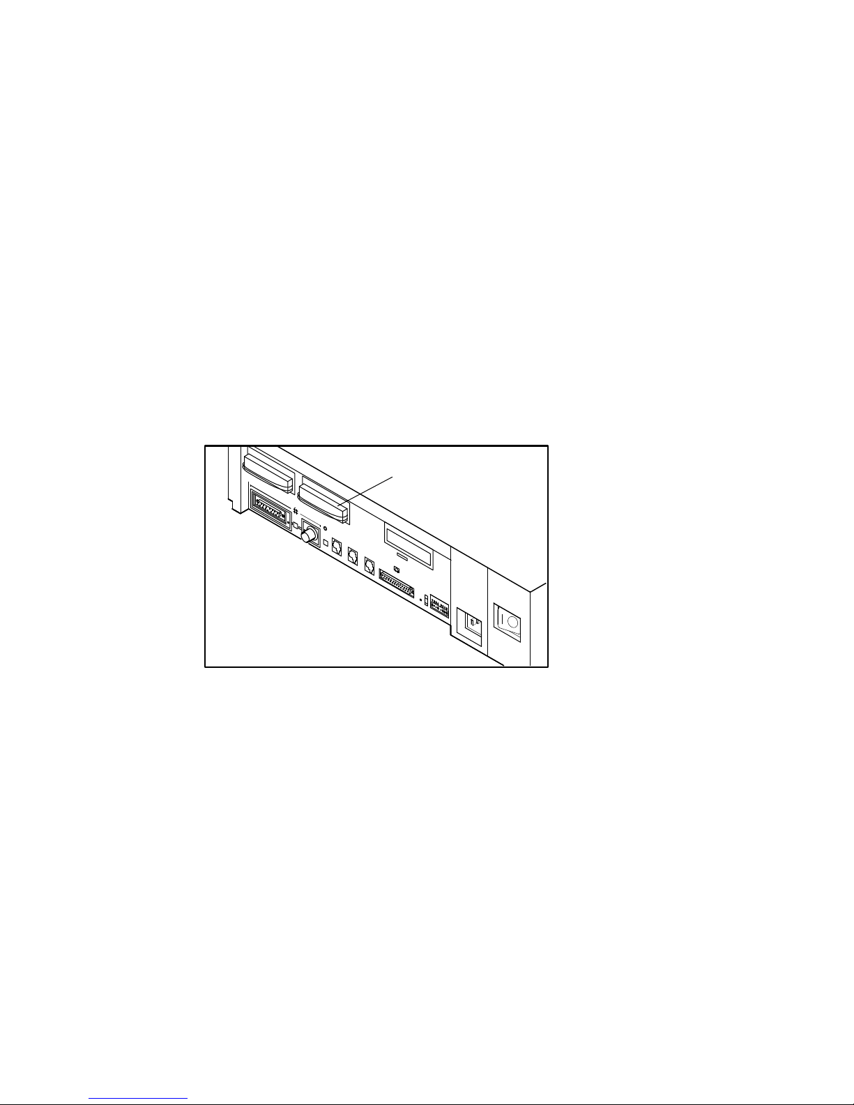
Figure 2–2 shows all the ports and connectors on the rear of an InfoServer
150 system. Take some time to become familiar with the ports and connectors.
Symbols (called icons) identify each port and connector you will use when
installing your system. Note that there are two SCSI ports. SCSI port A is at
the upper left and SCSI port B is next to it.
Figure 2–2 Ports and Connectors
SCSI Port
Standard Ethernet
Connector
Standard Ethernet Light
Network Select Button
ThinWire Ethernet Light
ThinWire Ethernet
Connector
Halt Button
1
MMJ Port
MMJ Ports
(Not Used)
Break Enable Switch
(For Field Service Use Only)
Diagnostic LEDs
Not all of the connectors shown are usable. In particular, MMJ ports 2
and 3 and the modem port (to the left of MMJ port 1) are not supported
by the server.
2–4
System AC Power
On/Off Switch
MKV-X3127-91
Note
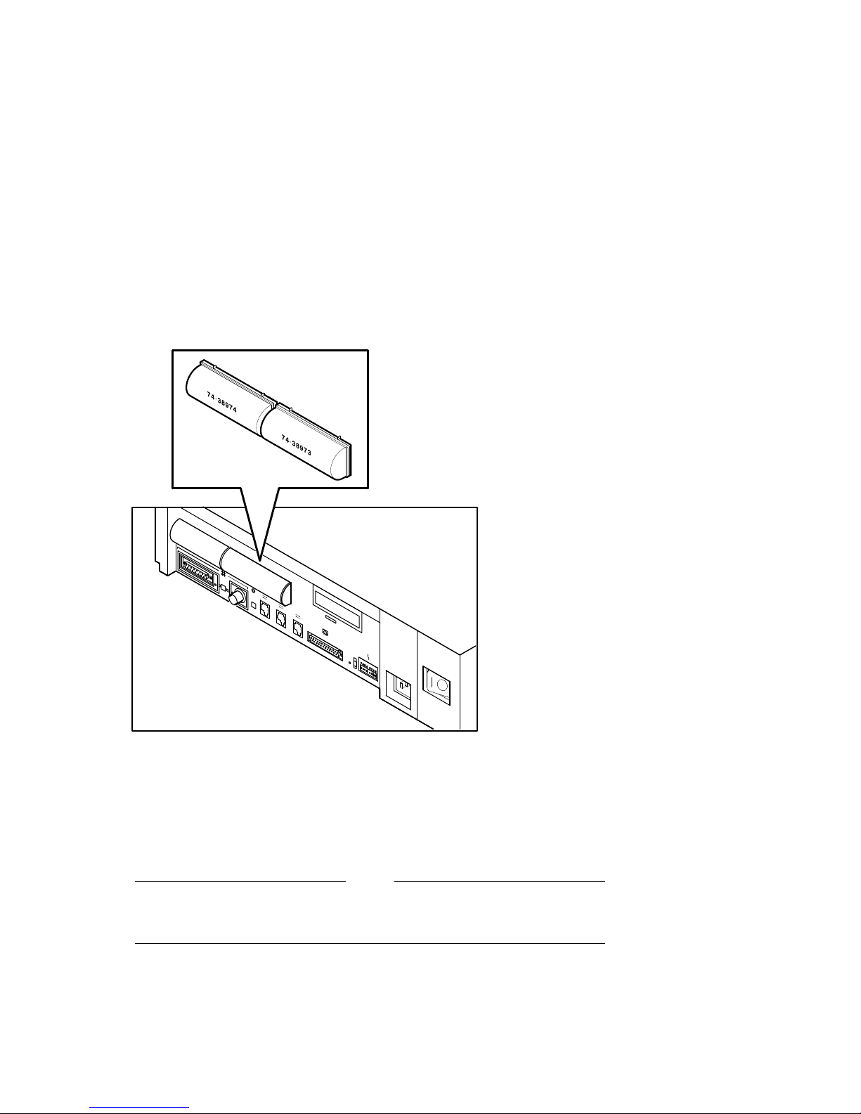
2.3.2 Install the SCSI Terminators
If you do not intend to connect additional drives to your system, be sure that
the SCSI terminators are installed on the SCSI ports at the rear of the system
unit, as shown in Figure 2–3.
Figure 2–3 Rear Panel with SCSI Terminators Installed
Installing Your System
2.3 Connecting System Components
SCSI Terminator
2.3.3 Install the Connector Covers
You system comes with two connector covers to protect the unused connectors
on the rear panel of the system unit, as shown in Figure 2–4
MKV-X3107-91
2–5
Installing Your System
2.3 Connecting System Components
Figure 2–4 Connector Covers
2
1
2.3.4 Attach the Ethernet Terminators
You must connect the T-connector, two Ethernet terminators, and the loopback
connector (Figure 2–1) to the system unit, so that you can run diagnostic tests
to verify the Ethernet circuits.
The system does not boot if the power-up self-test detects an Ethernet
error.
2–6
MKV-X3109-91
Note
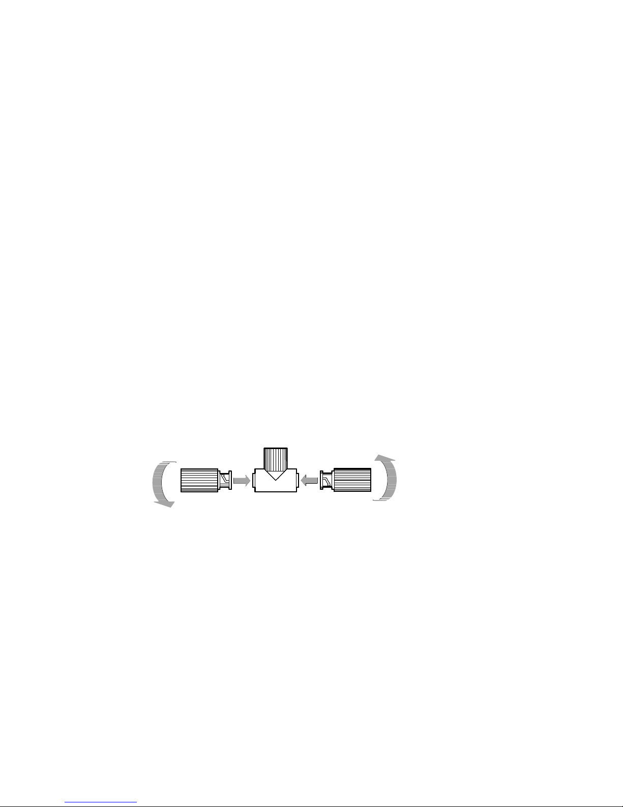
Installing Your System
2.3 Connecting System Components
For diagnostic purposes, note the following:
• The T-connector and two terminators complete the ThinWire Ethernet
circuit. Later, when you decide to connect to a network, you exchange
ThinWire cable sections for one or both terminators, depending on your
network setup.
• The loopback connector completes the standard Ethernet circuit.
To connect the T-connector and loopback connector, follow these steps:
1. Push one terminator into one side of the T-connector, then turn the
terminator clockwise until it locks in place.
2. Push the second terminator into the other side of the T-connector, then turn
the terminator clockwise until it locks in place, as shown in Figure 2–5.
Figure 2–5 Attaching T-connectors
T-Connector
Terminator
Terminator
MKV-X3110-91
3. Connect the T-connector to the ThinWire Ethernet connector on the rear
of the system unit by turning the T-connector clockwise until it locks into
place.
2–7
Installing Your System
2.3 Connecting System Components
T-Connector
4. Connect the loopback connector to the standard Ethernet port on the back
of the system unit. If needed, rotate the T-connector slightly to make room
for the loopback connector.
MKV-X3111-91
Ethernet
Loopback Connector
2–8
MKV-X3112-91

2.3 Connecting System Components
2.3.5 Connect the System Unit Power Cord
Note
Installing Your System
Make sure the
lO
power switch on the rear panel of the system unit
is off (O).
The system accepts power inputs in the ranges of 100 Vac to 120 Vac and 200
Vac to 240 Vac, at 50 or 60 Hertz. Within these limits the power supply is
self-sensing, so the system unit does not need a voltage selection switch.
Connect the supplied power cord to the power socket on the rear panel of the
system unit as shown in Figure 2–6. Connect the other end of the power cord
to a grounded power outlet.
Figure 2–6 Connecting the Power Cord
System Power Cord
MKV-X3113-91
2–9
Installing Your System
2.3 Connecting System Components
2.3.6 Connect a Console Terminal
You do not need a locally connected terminal for normal InfoServer operation.
However, Digital advises that you connect a local terminal as part of this
installation procedure, to ensure that the InfoServer system is operating
properly.
The recommended console terminal is a VT300 series terminal. When you
connect the terminal cable to one of the MMJ ports on the rear of the VT300
series terminal, the port must be set for DEC-423 operation. See your terminal
documentation for details.
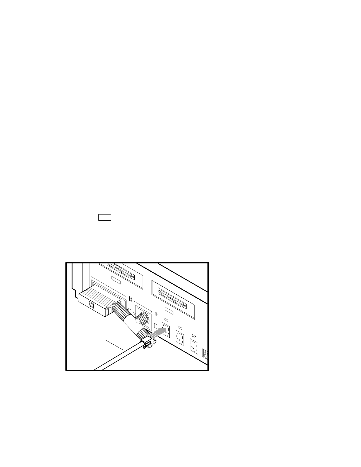
To connect a terminal to the server, follow these steps:
1. Make sure the
lO
power switch on the terminal is off (O).
2. Connect the terminal cable supplied with the system to MMJ port 1 on the
rear panel of the system unit.
Figure 2–7 Connecting the Console Terminal Cable
Local Terminal
Cable
MKV-X3114-91
3. Connect the other end of the console cable to the communications port on
the terminal.
4. The terminal must be set at 9600 baud, with 8 bits, and no parity. See
your terminal documentation if you need information on setting up your
terminal.
2–10

2.3 Connecting System Components
During normal operation, you can control the server through a LAT terminal
server session, if terminal servers are available on your network. If terminal
server access is not available, or if client systems have trouble accessing server
services, then a locally connected terminal is needed to manage the server or
diagnose server problems. See the InfoServer System Operations Guide.
2.3.7 Connect External Expansion Boxes
If you received expansion boxes with your system, you should connect them to
your system unit now. See Chapter 3 for information on connecting external
expansion boxes.
2.4 Starting the System
To start your system, follow these steps:
1. Turn on any expansion boxes connected to your system.
2. Turn on the console terminal connected to MMJ port 1. See your terminal
documentation. Note that a console terminal is required when the server is
first installed, to ensure proper startup and cabling.
Note
Installing Your System
To view the system power-up self-test display, you must allow time for
the console terminal to complete its power-up sequence.
3. Turn on the system unit by setting the
the system unit to the on ( | ) position.
The initial power-up display appears on the console terminal in about 1.5
minutes. If you see a display similar to the following, your system has
passed all power-up tests, and the terminal’s keyboard language has been
set:
KA41-2 V1.0
F_..E...D...C...B...A...9_..8...7...6...5...4_..3_..2_..1...
? E 0040 0000.0005
? C 0080 0000.4001
83 BOOT SYS
_DKA100
lO
power switch on the rear of
2–11

Installing Your System
2.4 Starting the System
The system now boots the internal RZ disc drive. If the boot is successful,
the console screen displays a message like the following:
DEC InfoServer 150 V2.0
Copyright (c) 1990, 1991 Digital Equipment Corp.
%ESS-I-INITDISK, Disk initialization complete, 14 devices found
4. Enter the system password (ESS) when the system displays the
Password:
If you do not see the power-up display or the server fails to bootstrap, turn
off the system unit and review each installation step. Repeat the power-up
procedure. If the problem continues, see Section 2.9.3.
Check the position of the break enable switch on the rear of the system
unit (Section 2.3.1). It should be in the down position.
prompt.
2.5 Loading a Compact Disc
The InfoServer 150 system (Figure 1–1) has one RRD42 compact disc drive on
the front of the system unit.
When you load a disc into the compact disc drive, insert the entire disc caddy
into the disc door on the drive. Do not remove the disc from the caddy.
To load compact discs that you want to serve to the network, follow these steps:
1. Examine the disc caddy. Make sure it is not cracked or damaged. Never
load a damaged caddy into a compact disc drive.
2. If a protective film is on the lid of the caddy, remove the film before using
the caddy (Figure 2–8).
Enter
Note
3. To open the lid of the caddy, press the tabs on both sides and lift the lid
(Figure 2–8).
2–12
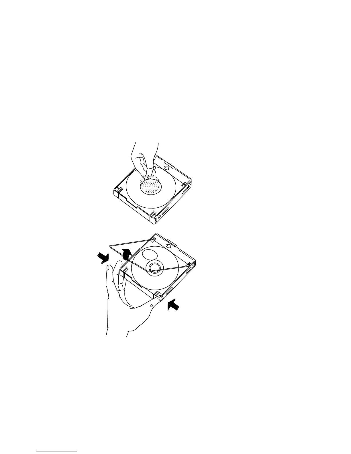
Figure 2–8 Opening the Caddy
Installing Your System
2.5 Loading a Compact Disc
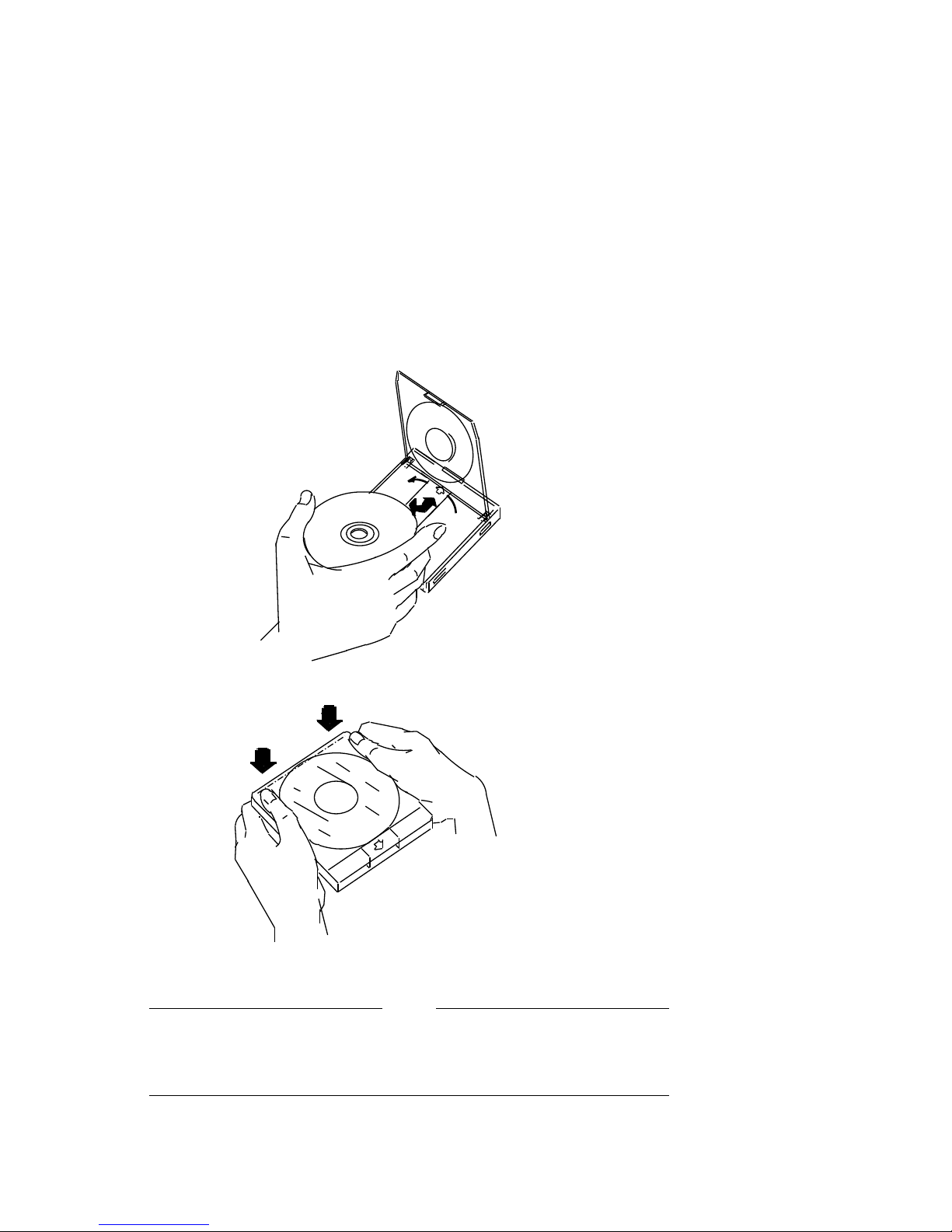
4. To load an empty caddy with a disc, hold the disc by the edges and place
the disc (with disc label up) into the caddy (Figure 2–9). Do not touch the
surface of the disc. Be sure to place the disc beneath the edge of the caddy.
5. Press both corners firmly to close the lid (Figure 2–9).
SHR−XR0070−90
2–13
Installing Your System
2.5 Loading a Compact Disc
Figure 2–9 Loading the Disc
The loading procedure for the RRD42 tabletop and embedded drives is
the same with one exception: the tabletop drive requires setting the
POWER switch to on. Figure 2–10 shows the tabletop drive.
2–14
SHR−XR0073−90
Note
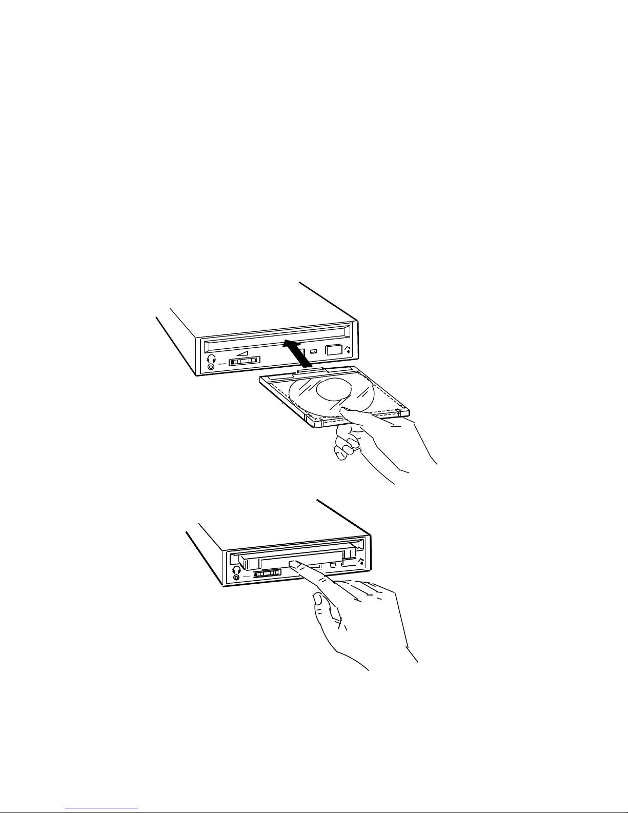
6. Insert the caddy into the drive (Figure 2–10).
Figure 2–10 Loading the Caddy in the Drive
Installing Your System
2.5 Loading a Compact Disc
SHR−XR0074−90A
SHR−XR0074−90
2–15
 Loading...