

Digital Equipment HSZ40 Reference Manual

DIGITAL StorageWorks
HSZ40 Array Controller
HSOF 3.1
CLI Reference Manual
Part Number: EK–CLI40–RM. B01
March 1997
Software Version:
Digital Equipment Corporation
Maynard, Massachusetts
HSOF Version 3.1

March 1997
While Digital Equipment Corporation believes the information included in this manual is correct as of the date of publication, it
is subject to change without notice. DIGITAL makes no representations that the interconnection of its products in the manner
described in this document will not infringe existing or future patent rights, nor do the descriptions contained in this document
imply the granting of licenses to make, use, or sell equipment or software in accordance with the description. No responsibility is
assumed for the use or reliability of firmware on equipment not supplied by DIGITAL or its affiliated companies. Possession,
use, or copying of the software or firmware described in this documentation is authorized only pursuant to a valid written license
from DIGITAL, an authorized sublicensor, or the identified licensor.
Commercial Computer Software, Computer Software Documentation and Technical Data for Commercial Items are licensed to
the U.S. Government with DIGITAL’S standard commercial license and, when applicable, the rights in DFAR 252.227-7015,
“Technical Data—Commercial Items.”
© Digital Equipment Corporation, 1997.
Printed in U.S.A.
All rights reserved.
CI, DIGITAL, HSC, HSJ, HSD, HSZ, OpenVMS, StorageWorks, VAX, VAXcluster, VMS, VMScluster, and the DIGITAL logo
are trademarks of Digital Equipment Corporation. All other trademarks and registered trademarks are the property of their
respective holders.
UNIX is a registered trademark in the United States and other countries licensed exclusively through X/Open Company LTD.
SUN is a registered trademark of Sun Microsystems Corp.
IBM is a registered trademark of International Business Machines Corp.
Windows NT is a registered trademark of Microsoft Corporation.
This equipment has been tested and found to comply with the limits for a Class A digital device, pursuant to Part 15 of the FCC
Rules. These limits are designed to provide reasonable protection against harmful interference when the equipment is operated
in a commercial environment. This equipment generates, uses and can radiate radio frequency energy and, if not installed and
used in accordance with the instruction manual, may cause harmful interference to radio communications. Operation of this
equipment in a residential area is likely to cause harmful interference in which case the user will be required to correct the
interference at his own expense. Restrictions apply to the use of the local-connection port on this series of controllers; failure to
observe these restrictions may result in harmful interference. Always disconnect this port as soon as possible after completing
the setup operation. Any changes or modifications made to this equipment may void the user's authority to operate the
equipment.
Warning!
This is a Class A product. In a domestic environment this product may cause radio interference in which case the user may be
required to take adequate measures.
Achtung!
Dieses ist ein Gerät der Funkstörgrenzwertklasse A. In Wohnbereichen können bei Betrieb dieses Gerätes Rundfunkstörungen
auftreten, in welchen Fällen der Benutzer für entsprechende Gegenmaßnahmen verantwortlich ist.
Avertissement!
Cet appareil est un appareil de Classe A. Dans un environnement résidentiel cet appareil peut provoquer des brouillages
radioélectriques. Dans ce cas, il peut être demandé à l’ utilisateur de prendre les mesures appropriées.

Table of Contents
1 Introduction to the CLI .............................................................1–1
CLI Overview.........................................................................................................1–2
Accessing and Exiting the CLI................................................................................1–3
Capturing Your CLI Session ...................................................................................1–4
Entering CLI Commands.........................................................................................1–4
Specifying the Device PTL .....................................................................................1–5
Syntax..............................................................................................................1–6
iii
2 CLI Commands..........................................................................2–1
ADD CDROM ........................................................................................................2–2
ADD DISK ............................................................................................................. 2–3
ADD MIRRORSET ................................................................................................ 2–5
ADD PASSTHROUGH...........................................................................................2–8
ADD RAIDSET....................................................................................................2–10
ADD SPARESET..................................................................................................2–13
ADD STRIPESET.................................................................................................2–14
ADD UNIT...........................................................................................................2–16
CLEAR_ERRORS CLI.........................................................................................2–22
CLEAR_ERRORS INVALID_CACHE.................................................................2–23
CLEAR_ERRORS LOST_DATA.........................................................................2–25
CLEAR_ERRORS UNKNOWN...........................................................................2–26
CLEAR_ERRORS UNWRITEABLE_DATA....................................................... 2–27
CREATE_PARTITION.........................................................................................2–28
DELETE container-name......................................................................................2–30
DELETE device-name ..........................................................................................2–31
DELETE FAILEDSET..........................................................................................2–32
HSZ40 Array Controller CLI Reference Manual

iv
DELETE SPARESET........................................................................................... 2–33
DELETE unit-number...........................................................................................2–34
DESTROY_PARTITION...................................................................................... 2–35
DIRECTORY .......................................................................................................2–36
EXIT.....................................................................................................................2–37
HELP.................................................................................................................... 2–38
INITIALIZE......................................................................................................... 2–39
LOCATE.............................................................................................................. 2–42
MIRROR .............................................................................................................. 2–44
REDUCE.............................................................................................................. 2–47
RENAME............................................................................................................. 2–49
RESTART THIS_CONTROLLER and RESTART OTHER_CONTROLLER......2–50
RETRY_ERRORS UNWRITEABLE_DATA....................................................... 2–52
RUN..................................................................................................................... 2–53
SELFTEST OTHER_CONTROLLER and SELFTEST THIS_CONTROLLER.... 2–54
SET device-name.................................................................................................. 2–56
SET FAILEDSET................................................................................................. 2–58
SET FAILOVER................................................................................................... 2–59
SET mirrorset-name..............................................................................................2–61
SET MULTIBUS_FAILOVER ............................................................................. 2–65
SET NOFAILOVER (SET NOMULTIBUS_FAILOVER).................................... 2–68
SET THIS_CONTROLLER and SET OTHER_CONTROLLER...........................2–70
SET RAIDset-name............................................................................................... 2–75
SET unit-number...................................................................................................2–77
SHOW.................................................................................................................. 2–82
SHUTDOWN THIS_CONTROLLER and SHUTDOWN OTHER_CONTROLLER2–86
UNMIRROR.........................................................................................................2–88
Glossary
Index
Figures
Figure 1–1 Identifying T
HIS_CONTROLLER
Figure 2–1 Controller Connections in Multiple Bus Failover Configuration....... 2–66
CLI Reference Manual HSZ40 Array Controller
THER_CONTROLLER
, O
..........................1–2

Related Documents
y
The following table lists some of the documents related to the use of this product.
Document title Part number
DECevent Installation Guide AA–Q73JA–TE
StorageWorks BA350–MA Controller Shelf User's
Guide
StorageWorks Configuration Manager for DEC
OSF/1 Installation Guide
StorageWorks Configuration Manager for DEC
OSF/1 System Manager's Guide for HSZterm
StorageWorks Solutions Configuration Guide EK–BA350–CG
StorageWorks Solutions Shelf and SBB User's
Guide
StorageWorks Solutions SW300-Series RAID
Enclosure Installation and User's Guide
StorageWorks SW500-Series Cabinet Installation
and User's Guide
StorageWorks SW800-Series Data Center Cabinet
Installation and User's Guide
The RAIDBOOK—A Source for RAID
Technology
Polycenter Console Manager User's Guide Computer Associates
VAXcluster Systems Guidelines for VAXcluster
System Configurations
16-Bit SBB User’s Guide EK-SBB16-UG
7-Bit SBB Shelf (BA356 Series) User’s Guide EK-BA356-UG
SBB User’s Guide EK-SBB35-UG
v
EK–350MA–UG
AA–QC38A–TE
AA–QC39A–TE
EK–BA350–UG
EK–SW300–UG
EK–SW500–UG
EK–SW800–UG
RAID Advisor
Board
EK–VAXCS–CG
HSZ40 Array Controller CLI Reference Manual


1
Introduction to the CLI
CLI Overview
How to Access and Exit the CLI
Entering CLI Commands
HSZ40 Array Controller CLI Reference Manual
1–2 Introduction to the CLI
CLI Overview
The command line interpreter (CLI) is one of the user interfaces to the StorageWorks™
array controllers in your subsystem. The CLI commands allow you to manage the
subsystem by viewing and modifying the configuration of the controllers and the devices
attached to them. You also use the CLI to start controller diagnostic and utility programs.
CLI commands for configuring and viewing the controllers use the relative terms
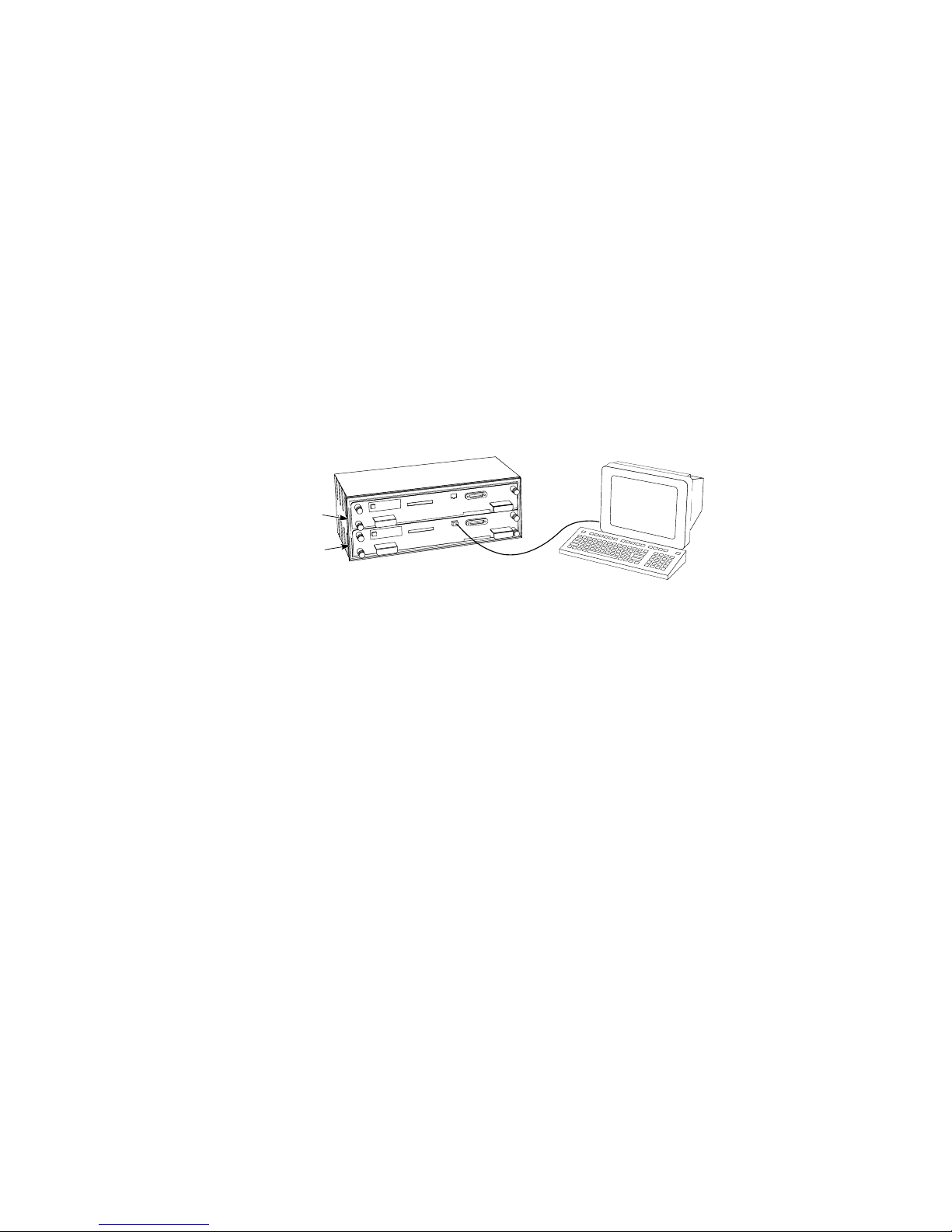
THIS_CONTROLLER and OTHER_CONTROLLER. T
the controller that is running the current CLI session. You may have a maintenance
terminal or PC directly connected to the terminal port on the front of the controller, or you
may be using a virtual terminal connection through the host bus. In either case,
HIS_CONTROLLER
T
is the one that you are interacting with directly. This is shown in Figure
1–1.
HIS_CONTROLLER
always refers to
Figure 1–1 Identifying T
OTHER_CONTROLLER
THIS_CONTROLLER
THER_CONTROLLER
O
always refers to the controller that is not running the current CLI
HIS_CONTROLLER
THER_CONTROLLER
, O
CXO-5193A-MC
sessionthe one that is not connected to a terminal or terminal session.
CLI Reference Manual HSZ40 Array Controller

Introduction to the CLI 1–3
Accessing and Exiting the CLI
__________________________ Note _____________________________
The maintenance terminal port on the controller is meant to be used only for
initial configuration and required maintenance functions. Operation of this port
may cause harmful radio frequency interference. Always disconnect the terminal
and cable when you have finished working with the controller.
____________________________________________________________
You can access the CLI from a maintenance terminal connected to the front bezel of the
controller (local connection) or through the host operating system using a VAXcluster™
system console (VCS), a diagnostic and utility protocol (DUP), or an HSZterm (remote
connection). You must use a local connection to perform initial controller configuration,
such as setting the controller ID. Once you have completed initial configuration and the
controller is visible on the host bus, you can perform all other configuration through a
remote connection.
In a dual-redundant controller configuration, you can view and set the configurations of
both controllers with one local or remote connection. Use T
change the configuration on the controller that is running the CLI session. Use
THER_CONTROLLER
O
commands to view or change the configuration on the partner
controller.
HIS_CONTROLLER
commands to
If you are using a remote DUP connection to the CLI, enter the
EXIT
command at the CLI
prompt to close the connection. You do not need to exit from a local connection.
HSZ40 Array Controller CLI Reference Manual

1–4 Introduction to the CLI
p
g
g
g
p
y
Capturing Your CLI Session
If you are using a remote terminal connection via DUP on an OpenVMS™ system and you
specify the /LOG switch on your command line, a log file of your CLI session is created.
You must use the
EXIT
command to exit the CLI in order to close and print the log file.
Entering CLI Commands
Use the following tips and techniques when entering CLI commands:
• Commands are not case sensitive.
• With few exceptions, you only need to enter enough of each command to make the
command unique (usually three characters). For example,
SHO
is equivalent to
• While the controller is processing a command, you can enter succeeding commands
without waiting for the CLI prompt. The controller will process each command when
it has completed the previous command. (A unit that is experiencing heavy I/O load
may be slow to respond to CLI commands.)
SHOW
.
• You can enter only one switch (or “qualifier”) with each
multiple switches for the same device or unit, you must use multiple
SET
command. To enter
SET
commands.
You can recall and edit the last five commands. This feature can save time and help
prevent mistakes when you need to enter similar commands during configuration. Use the
following keys to recall and edit commands:
Key Function
Up Arrow or Ctrl/B,
Down Arrow or
Ctrl/N
Left arrow or Ctrl/D,
Ri
ht arrow or
Ctrl/F
Ctrl/E Moves the cursor to the end of the line.
Ctrl/H or Backspace Moves the cursor to the beginning of the line.
Ctrl/J or Linefeed Deletes the word to the left of the cursor.
Ctrl/U Deletes characters from the beginning of the line to the cursor.
Ctrl/A Toggles between insert mode and overstrike mode. The default
Ctrl/R Recalls the contents of the command line. This is especiall
Ste
s backward and forward through the five most recent CLI
commands.
Moves the cursor left or right in a command line.
settin
is insert mode, which allows you to insert characters at the
cursor location, movin
Overstrike mode re
CLI returns to insert mode at the beginning of each line.
helpful if the system issues a message that interrupts your typing.
the existing characters to the right.
laces existing characters when you type. The
CLI Reference Manual HSZ40 Array Controller

Introduction to the CLI 1–5
Specifying the Device PTL
Units accessed by the controller are commonly called logical units (LUN). Each logical
unit has a number that is device addressable through a target. Often, a command requires
that a device’s port-target-LUN (PTL) address be entered. The PTL address is a five-digit
address by which the controller identifies the location of the device.
• P—Designates the controller’s SCSI port number (1 through 6 for 6-port controllers).
• T—Designates the target identification (ID) number of the device. Valid target ID
numbers for a single-controller configuration are 0 through 6. Valid target ID numbers
for a dual-redundant-controller configuration are 0 through 5.
• L—Designates the LUN of the device (must be 0).
Place one space between the port number, target number, and the two-digit LUN number
when entering the PTL address. An example of a PTL address follows:
1 02 00
__________________________ Note _____________________________
DIGITAL UNIX
®
requires passthrough units to be at LUN 0. OpenVMS accepts
LUN numbers 0 through 7.
____________________________________________________________
HSZ40 Array Controller CLI Reference Manual

1–6 Introduction to the CLI
Syntax
Commands to the controller must match the following command structure:
COMMAND PARAMETER SWITCHES
Q
Command—Instructs the controller to do something. For example, the SET
command instructs the controller to set something.
Q
Parameter—The object that receives the command and is assigned the task
of processing the command.
Q
Switches—Reserved words that have a special function. For example, the
member switch indicates that the term after it is the name or number of the
storage member.
CLI Reference Manual HSZ40 Array Controller

2
CLI Commands
Descriptions of all CLI Commands
Required Parameters
Optional Switches
Examples

2–2 ADD CDROM
ADD CDROM
Adds a CD–ROM drive to the controller configuration and names the drive.
Format
ADD CDROM
Parameters
CDROM-name
Specifies a name for the CD−ROM drive. You use this name with the
to identify the CD−ROM drive as a host-addressable unit.
The name must start with a letter (A–Z) and can then consist of up to eight more
characters made up of letters A-Z, numbers 0-9, periods (.), dashes (-), or underscores (_),
for a total of nine characters.
SCSI-location
The SCSI-Location parameter assigns a PTL address to the CD-ROM that is used by the
controller. See page 1–5, Specifying the Device PTL, for an explanation of the PTL
numbering system.
Examples
To add a CD−ROM drive at port 1, target 0, LUN 0, named CD_PLAYER:
CDROM-name SCSI-location
ADD UNIT
command
See also
CLI> ADD CDROM CD_PLAYER 1 0 0
ADD UNIT
DELETE
SHOW CDROM

ADD DISK 2–3
ADD DISK
Adds a disk drive to the controller configuration and names the drive.
Format
ADD DISK
Parameters
disk-name
Specifies a name for the disk drive. You use this name when adding the disk drive to a
storageset or with the
The name must start with a letter (A–Z) and can then consist of up to eight more
characters made up of letters A-Z, numbers 0-9, periods (.), dashes (-), or underscores (_),
for a total of nine characters.
SCSI-location
The SCSI-location parameter assigns a PTL address to the disk drive. See page 1–5,
Specifying the Device PTL, for an explanation of the PTL numbering system.
Switches
disk-name SCSI-location
ADD UNIT
command to create a single-disk host-addressable unit.
TRANSPORTABLE
NOTRANSPORTABLE (Default)
Specify the
TRANSPORTABLE
switch for any disk drive that you want to move to and from
StorageWorks environments with the data intact.
__________________________ Note _____________________________
Use the
TRANSPORTABLE
switch only for disk drives that must be moved to
StorageWorks environments with data intact.
____________________________________________________________
TRANSPORTABLE
A
disk drive does not contain any special information space and can be
moved to a non-StorageWorks environment with its data intact. You cannot use a
TRANSPORTABLE
Specify
NOTRANSPORTABLE
mirrorsets. Also use the
disk drive in any type of storageset, such as a stripeset or RAIDset.
for all disk drives that will be used in RAIDsets, stripesets, and
NOTRANSPORTABLE
switch for all single-disk units that will be
used exclusively in a StorageWorks or HSC™ controller.
The controller makes a small portion of nontransportable
disk drives inaccessible to the
host and uses the space to store information (metadata) that improves data reliability, error
detection, and recovery. Because of this metadata, only StorageWorks controllers can
retrieve user data from nontransportable disk drives.
HSZ40 Array Controller CLI Reference Manual

2–4 ADD DISK
Examples
To add nontransportable DISK100 at port 1, target 0, LUN 0:
CLI> ADD DISK DISK100 1 0 0
To add transportable disk DISK230 at port 2, target 3, LUN 0:
CLI> ADD DISK DISK230 2 3 0 TRANSPORTABLE
See also
DELETE
LOCATE
SHOW DISKS
SET disk-name

ADD MIRRORSET 2–5
ADD MIRRORSET
Adds a mirrorset to the controller configuration and names the mirrorset. The number of
members is set to the number of devices specified in the command.
Format
ADD MIRRORSET
Parameters
mirrorset-name
Specifies a name for the mirrorset. You use this name with the
identify the mirrorset as a host-addressable unit.
The name must start with a letter (A–Z) and can then consist of up to eight more
characters made up of letters A-Z, numbers 0-9, periods (.), dashes (-), or underscores (_),
for a total of nine characters.
disk-name1 disk-nameN
The names of the disk drives that make up the mirrorset. A mirrorset contains 1 to 6 disk
drives.
Switches
mirrorset-name disk-name1 [disk-nameN]
ADD UNIT
command to
COPY=NORMAL (Default)
COPY=FAST
__________________________ Note _____________________________
A normal mirrorset member is one whose entire contents are the same as all
other normal members.
____________________________________________________________
COPY
The
switch allows you to set the speed at which the controller copies data from
normal mirrorset members to new members.
NORMAL
Select
to prioritize other controller operations over the copy operation. The
controller uses relatively few resources to perform the copy, and there is little impact on
performance.
FAST
Select
when the copy operation must take precedence over other controller
operations. The controller uses more resources and the copy takes less time, but overall
controller performance is reduced during the copy.
HSZ40 Array Controller CLI Reference Manual

2–6 ADD MIRRORSET
POLICY=BEST_FIT
POLICY=BEST_PERFORMANCE (Default)
NOPOLICY
POLICY
The
switch allows you to set the criteria the controller uses to choose a replacement
member from the spareset when a mirrorset member fails.
BEST_FIT
Select
to choose a replacement device from the spareset that most closely
matches the capacities of the remaining members. If more than one device in the spareset
is the correct size, the controller selects the device that gives the best performance.
BEST_PERFORMANCE
Select
to choose a replacement device from the spareset that results in
the best performance (the device should be on a different port than existing members). If
more than one device in the spareset has the best performance, the controller selects the
device that most closely matches the size of the remaining members.
READ_SOURCE=ROUND_ROBIN
READ_SOURCE=LEAST_BUSY (Default)
READ_SOURCE=disk-name
READ_SOURCE
The
switch allows you to control which mirrorset member is used by the
controller to satisfy a read request.
Select
mirrorset member in sequential membership order. No preference is given to any
member.
Select
member with the least busy work queue.
Select the disk-name of a specific member to cause the controller to direct all read requests
to that member. If that member fails out of the mirrorset, the controller reverts to the
LEAST_BUSY
Examples
To add DISK100, DISK210, and DISK320 as a mirrorset with the name MIRR1:
CLI> ADD DISK DISK100 1 0 0
CLI> ADD DISK DISK210 2 1 0
CLI> ADD DISK DISK320 3 2 0
CLI> ADD MIRRORSET MIRR1 DISK100 DISK210 DISK320
CLI> INITIALIZE MIRR1
CLI> ADD UNIT D305 MIRR1
ROUND_ROBIN
LEAST_BUSY
to cause the controller to direct read requests to each
to cause the controller to direct read requests to the
method for mirrorset read requests.
NORMAL
NORMAL
NORMAL
mirrorset

ADD MIRRORSET 2–7
See also
ADD DISK
DELETE
INITIALIZE
MIRROR
REDUCE
SHOW MIRRORSETS
UNMIRROR
HSZ40 Array Controller CLI Reference Manual

2–8 ADD PASSTHROUGH
ADD PASSTHROUGH
Creates a passthrough container (command disk) to allow direct access to a device. HSZ
controllers use passthrough containers to communicate with tape drives and tape loaders.
Format
For tape drives and loaders attached to HSZ controllers:
ADD PASSTHROUGH
Parameters
passthrough-name
Specifies a name for the passthrough container. You use this name with the
command to identify the passthrough container as a host-addressable unit. You may want
to use a name that indicates the type of device served by the passthrough container, such as
“TAPE” or “LOADER.”
The name must start with a letter (A–Z) and can then consist of up to eight more
characters made up of letters A-Z, numbers 0-9, periods (.), dashes (-), or underscores (_),
for a total of nine characters.
SCSI-location
The SCSI-location parameter assigns a PTL address to the drive or loader. See page 1–5,
Specifying the Device PTL, for an explanation of the PTL numbering system.
passthrough-name SCSI-location
ADD UNIT

ADD PASSTHROUGH 2–9
Examples
__________________________ Note _____________________________
DIGITAL UNIX requires HSZ passthrough units to be at LUN 0 (the third digit
in the unit number). OpenVMS accepts LUN numbers 0-7.
____________________________________________________________
To add tape drive TAPE230 at port 2, target 3, LUN 0:
CLI> ADD PASSTHROUGH TAPE230 2 3 0
CLI> ADD UNIT P100 TAPE230
See also
ADD UNIT
DELETE
SHOW PASSTHROUGH
HSZ40 Array Controller CLI Reference Manual

2–10 ADD RAIDSET
ADD RAIDSET
Creates a RAIDset from 3 to 14 disks.
Format
ADD RAIDSET
Parameters
RAIDset-name
Specifies a name for the RAIDset. You use this name with the
identify the RAIDset as a host-addressable unit.
The name must start with a letter (A–Z) and can then consist of up to eight more
characters made up of letters A-Z, numbers 0-9, periods (.), dashes (-), or underscores (_),
for a total of nine characters.
disk-name1 disk-name2 disk-nameN
The disks that will make up the RAIDset. A RAIDset can contain 3 to 14 member disks.
Switches
POLICY=BEST_FIT
POLICY=BEST_PERFORMANCE (Default)
NOPOLICY
The
member from the spareset when a RAIDset member fails.
POLICY
RAIDset-name disk-name1 disk-name2 [disk-nameN]
ADD UNIT
command to
switch allows you to set the criteria the controller uses to choose a replacement
BEST_FIT
Select
to choose a replacement device from the spareset that most closely
matches the capacities of the remaining members. If more than one device in the spareset
is the correct size, the controller selects the device that gives the best performance.
BEST_PERFORMANCE
Select
to choose a replacement device from the spareset that results in
the best performance (the device should be on a different port than existing members). If
more than one device in the spareset has the best performance, the controller selects the
device that most closely matches the size of the remaining members.
NOPOLICY
Select
the RAIDset to run in a reduced state until a
selected, or a member is manually replaced in the RAIDset (see
to prevent the controller from replacing a failed disk drive. This causes
BEST_FIT
BEST_PERFORMANCE
or
SET
RAIDset-name).
policy is
RECONSTRUCT=NORMAL (Default)
RECONSTRUCT=FAST
RECONSTRUCT
The
switch allows you to set the speed at which the controller reconstructs
the data on a new RAIDset member that has replaced a failed member.

ADD RAIDSET 2–11
NORMAL
Select
to balance other controller operations against the reconstruct operation.
The controller uses relatively few resources to perform the reconstruct, and there is little
impact on performance.
FAST
Select
when the reconstruct operation must take precedence over other controller
operations. The controller uses more resources and the reconstruct takes less time, but
overall controller performance is reduced during the reconstruct.
REDUCED
NOREDUCED (Default)
REDUCED
The
need to use the
NOREDUCED
The
switch allows you to add a RAIDset that is missing one member. You only
REDUCED
switch if you are re-adding a reduced RAIDset to the subsystem.
setting is the default and indicates that all RAIDset members that make
up the RAIDset are being specified, such as when creating a new RAIDset.
Examples
To create RAIDset RAID9 with disks DISK100, DISK210, and DISK320:
CLI> ADD DISK DISK100 1 0 0
CLI> ADD DISK DISK210 2 1 0
CLI> ADD DISK DISK320 3 2 0
CLI> ADD RAIDSET RAID9 DISK100 DISK210 DISK320
CLI> INITIALIZE RAID9
CLI> ADD UNIT D204 RAID9
To create RAIDset RAID8 with disks DISK100, DISK210, and DISK320, and use the
BEST_FIT
CLI> ADD DISK DISK100 1 0 0
CLI> ADD DISK DISK210 2 1 0
CLI> ADD DISK DISK320 3 2 0
CLI> ADD RAIDSET RAID8 DISK100 DISK210 DISK320 POLICY=BEST_FIT
CLI> INITIALIZE RAID8
CLI> ADD UNIT D205 RAID8
replacement policy:
This example shows creating a three-member RAIDset from the members of a fourmember RAIDset that was already reduced. Note that you must not initialize the RAIDset,
because it was initialized in its previous location.
CLI> ADD DISK DISK100 1 3 0
CLI> ADD DISK DISK210 2 4 0
CLI> ADD DISK DISK320 3 5 0
CLI> ADD RAIDSET RAID6 DISK130 DISK240 DISK350 REDUCED
CLI> ADD UNIT D205 RAID6
HSZ40 Array Controller CLI Reference Manual

2–12 ADD RAIDSET
See also
ADD UNIT
DELETE
SET RAIDSET
SHOW RAIDSET
INITIALIZE

ADD SPARESET 2–13
ADD SPARESET
Adds a disk drive to the spareset and initializes the metadata on the drive. The spareset is a
pool of disk drives available to the controller to replace failing members of RAIDsets and
mirrorsets.
Format
ADD SPARESET
Parameters
disk-name
The name of the disk drive to add to the spareset. You can add only one drive to the
spareset with each command.
Examples
To add DISK220 and DISK330 to the spareset:
CLI> ADD DISK DISK220 2 2 0
CLI> ADD DISK DISK330 3 3 0
CLI> ADD SPARESET DISK220
CLI> ADD SPARESET DISK330
disk-name
See also
DELETE SPARESET
SET FAILEDSET
SHOW SPARESET
HSZ40 Array Controller CLI Reference Manual

2–14 ADD STRIPESET
ADD STRIPESET
Creates a stripeset out of 2 to 14 disks or mirrorsets.
Format
ADD STRIPESET
Parameters
stripeset-name
Specifies a name for the stripeset. You use this name with the
identify the stripeset as a host-addressable unit.
The name must start with a letter (A–Z) and can then consist of up to eight more
characters made up of letters A-Z, numbers 0-9, periods (.), dashes (-), or underscores (_),
for a total of nine characters.
container-name1 container-nameN
The names of the disk drives or mirrorsets that make up the stripeset. A stripeset can be
made up of from 2 to 14 containers.
Examples
To create stripeset STRIPE1 with three disks: DISK100, DISK210, and DISK320:
stripeset-name container-name1 [container-nameN]
ADD UNIT
command to
CLI> ADD DISK DISK100 1 0 0
CLI> ADD DISK DISK210 2 1 0
CLI> ADD DISK DISK320 3 2 0
CLI> ADD STRIPESET STRIPE1 DISK100 DISK210 DISK320
CLI> INITIALIZE STRIPE1
CLI> ADD UNIT D403 STRIPE1
The next example shows creating a two-member striped mirrorset (a stripeset whose
members are mirrorsets). Note that you only need to initialize the stripeset; you do not
need to initialize the mirrorsets individually.
CLI> ADD DISK DISK100 1 0 0
CLI> ADD DISK DISK210 2 1 0
CLI> ADD DISK DISK320 3 2 0
CLI> ADD DISK DISK430 4 3 0
CLI> ADD MIRRORSET MR1 DISK100 DISK210
CLI> ADD MIRRORSET MR2 DISK320 DISK430
CLI> ADD STRIPESET STRIPE1 MR1 MR2
CLI> INITIALIZE STRIPE1
CLI> ADD UNIT D304 STRIPE1

ADD STRIPESET 2–15
See also
ADD UNIT
ADD MIRRORSET
DELETE
INITIALIZE
SHOW STRIPESET
HSZ40 Array Controller CLI Reference Manual
2–16 ADD UNIT
ADD UNIT
Identifies a device, container, or partition as a host-addressable logical unit. The controller
maps all requests from the host to the logical unit number as requests to the container
specified in the ADD UNIT command.
You must initialize the disk drive or container before you can add it as a unit.
Format
ADD UNIT
Parameters
unit-number
A number such as D104, where D represents a device-type letter, 1 is one of the controller
target IDs, and the 4 is a logical unit number (the middle number is always 0).
The device type letter is either “D” for disk containers (including CD–ROMs) or “P” for
passthrough containers created from tape drives and loaders.
The controller target ID must be in the range 0 to 7, and must be one of the IDs set with
SET THIS_CONTROLLER ID
the
out the target ID if it is 0, and only use the logical unit number.
unit-number container-name
SET OTHER_CONTROLLER ID
and
commands. You must leave
The logical unit number must be in the range 0 to 7. You can assign up to eight logical
units for each controller target ID.
Table 2–1 breaks out the components in HSZ unit numbering.
Table 2–1 HSZ Unit Numbering
Unit number Device type Target ID LUN
D401 Disk 4 1
P100 Passthrough 1 0
D5 Disk 0 5
On a partitioned container, all of the partitions must be addressed through a single
controller. Thus, the unit numbers for all partitions on a container must have the same
controller target ID.
container-name
The name of the container that is used to create the unit.
ADD UNIT 2–17
Switches
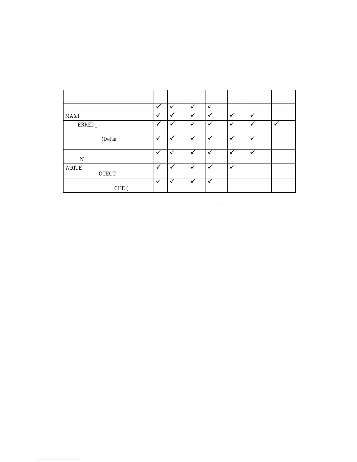
Table 2–2 lists all switches for the
used with each type of device and storageset. Descriptions of the switches follow the table.
Table 2–2 Switches for the ADD UNIT Command
ADD UNIT
command and shows which switches can be
Switch RAID
PARTITION=partition_number
MAXIMUM_CACHED_TRANSFER
PREFERRED_PATH
NOPREFERRED_PATH (Default)
READ_CACHE (Default)
NOREAD_CACHE
RUN (Default)
NORUN
WRITE_PROTECT
NOWRITE_PROTECT (Default)
WRITEBACK_CACHE
NOWRITEBACK_CACHE (Default)
- set
99 9 9
99 9 9 9 9
99 9 9 9 9 9
99 9 9 9 9
99 9 9 9 9
99 9 9 9
99 9 9
__________________________ Note _____________________________
The RUN/NORUN switch cannot be specified for partitioned units.
____________________________________________________________
PARTITION=partition_number
PARTITION
The
single-disk unit. Use the
switch allows you to set the unit number for a partition on a storageset or
partition-number
adding the host-addressable unit number. (Use the
numbers for a storageset or single-disk unit.)
Stripeset
Mirrorset
NoTrans
Disk
Trans
Disk
CD–ROM Pass-
through
to identify the partition for which you are
SHOW
command to find partition
MAXIMUM_CACHED_TRANSFER=n
MAXIMUM_CACHED_TRANSFER=32 (Default)
MAXIMUM_CACHED_TRANSFER
The
switch allows you to set the largest transfer (in blocks)
to be cached by the controller. The controller will not cache any transfers over this size.
Valid values are 1–1024.
HSZ40 Array Controller CLI Reference Manual

2–18 ADD UNIT
PREFERRED_PATH=THIS_CONTROLLER
PREFERRED_PATH=OTHER_CONTROLLER
NOPREFERRED_PATH (Default)
___________________________Note ____________________________
All partitions on a container must be addressed through the same controller. If
you set
PREFERRED_PATH
for one partition, all partitions on that container will
inherit the same path.
____________________________________________________________
PREFERRED_PATH
The
through which the unit will be accessed. If you set
switch allows you to balance I/O load by specifying the controller
NOPREFERRED_PATH
for a unit, it can be
accessed through either controller.
The controllers only use the
PREFERRED_PATH
setting if they are in a dual-redundant
configuration. If one controller fails, all the devices are accessed through the remaining
controller, ignoring the
PREFERRED_PATH
setting.
___________________________Note ____________________________
PREFERRED_PATH
The
NOPREFERRED_PATH
and
switches are valid only for HSZ
controllers in dual-redundant multiple bus-failover configurations. The preferred
path for units on dual-redundant HSZ controllers is determined by the first digit
in the unit number (the controller target ID) specified in the
ADD UNIT
command.
____________________________________________________________
When the failed controller is restarted, the drives automatically return to the controller
specified by the
You can specify the
PREFERRED_PATH
PREFERRED_PATH
switch.
switch on a single controller; however, the switch
will not take effect until you add a second controller and configure the two controllers for
dual-redundancy.
READ_CACHE (Default)
NOREAD_CACHE
READ_CACHE
The
switch allows you to enable or disable the use of read cache with a unit.
Read caching improves performance in almost all situations, so it is generally good to
leave it enabled. However, under certain workloads, like a backup, there may be a low
probability for a cache hit and it may be beneficial to turn read caching off to remove the
overhead of caching.
RUN (Default)
NORUN
RUN
The
switch allows you to enable and disable a unit's availability to the host.
 Loading...