

Digital Equipment HA3000 Installation Manual

HA300020-80kVA
UninterruptiblePowerSystem
InstallationManual
Order Number EK-HA32X-IN-002
Digital Equipment Corporation

November 1991
The information in this document is subject to change without notice and should not be construed as a
commitment by Digital Equipment Corporation. Digital Equipment Corporation assumes no responsibility for
any errors that may appear in this document.
Possession, use, duplication, or dissemination of the software described in this documentation is authorized
only pursuant to a valid written license from Digital or the third-party owner of the software copyright.
No responsibility is assumed for the use or reliability of software on equipment that is not supplied by
Digital Equipment Corporation.
Copyright © Digital Equipment Corporation 1991
All Rights Reserved.
Printed in U.S.A.
The postpaid Reader’s Comment Card included in this document requests the user’s critical evaluation to
assist in preparing future documentation.
FCC NOTICE: The equipment described in this manual generates, uses, and may emit radio frequency
energy. The equipment has been type tested and found to comply with the limits for a Class A computing
device pursuant to Subpart J of Part 15 of FCC Rules, which are designed to provide reasonable protection
against such radio frequency interference when operated in a commercial environment. Operation of this
equipment in a residential area may cause interference, in which case the user at his own expense may be
required to take measures to correct the interference.
The Digital logo is a trademark of Digital Equipment Corporation.
This document was prepared and published by Educational Services Development and Publishing, Digital
Equipment Corporation.

Contents
About This Manual ix
1 INSTALLATION REFERENCE CHECKLISTS
1.1 CUSTOMER RESPONSIBILITIES . . . . . . . . . . . . . . . . . . . . . . . . . . . . 1–1
1.1.1 Site Preparation . . . . . . . . . . . . . . . . . . . . . . . . . . . . . . . . . . . . . . . . 1–1
1.1.2 Delivery/Handling . . . . . . . . . . . . . . . . . . . . . . . . . . . . . . . . . . . . . . . 1–2
1.2 TRUCKER/MOVER/RIGGER RESPONSIBILITIES . . . . . . . . . . . . . . . 1–3
1.3 ELECTRICIAN RESPONSIBILITIES . . . . . . . . . . . . . . . . . . . . . . . . . . 1–3
1.3.1 HA32A UPS Cabinet . . . . . . . . . . . . . . . . . . . . . . . . . . . . . . . . . . . . . 1–3
1.3.2 HA32B UPS Battery Cabinet . . . . . . . . . . . . . . . . . . . . . . . . . . . . . . 1–4
1.3.3 HA32C/D/E UPS Auxiliary Cabinet . . . . . . . . . . . . . . . . . . . . . . . . . 1–5
1.3.4 HA33D/F UPS CSA Cabinet . . . . . . . . . . . . . . . . . . . . . . . . . . . . . . . 1–6
1.3.5 HA32J/K UPS Distribution Cabinet . . . . . . . . . . . . . . . . . . . . . . . . . 1–7
1.3.6 HA320-A3 Remote Alarm Panel . . . . . . . . . . . . . . . . . . . . . . . . . . . . 1–8
1.4 DIGITAL SERVICES RESPONSIBILITIES . . . . . . . . . . . . . . . . . . . . . 1–9
1.4.1 Site Preparation . . . . . . . . . . . . . . . . . . . . . . . . . . . . . . . . . . . . . . . . 1–9
1.4.2 Delivery/Handling . . . . . . . . . . . . . . . . . . . . . . . . . . . . . . . . . . . . . . . 1–10
1.4.3 Initial Startup . . . . . . . . . . . . . . . . . . . . . . . . . . . . . . . . . . . . . . . . . . 1–10
2 SITE PREPARATION
2.1 GENERAL . . . . . . . . . . . . . . . . . . . . . . . . . . . . . . . . . . . . . . . . . . . . . . 2–1
2.2 STORAGE . . . . . . . . . . . . . . . . . . . . . . . . . . . . . . . . . . . . . . . . . . . . . . . 2–1
2.3 HA32A UPS CABINET . . . . . . . . . . . . . . . . . . . . . . . . . . . . . . . . . . . . . 2–2
2.4 HA32B UPS BATTERY CABINET . . . . . . . . . . . . . . . . . . . . . . . . . . . . 2–6
2.4.1 Environmental Considerations . . . . . . . . . . . . . . . . . . . . . . . . . . . . . 2–6
2.4.2 Mechanical Considerations . . . . . . . . . . . . . . . . . . . . . . . . . . . . . . . . 2–6
2.5 HA32C/D/E UPS AUXILIARY CABINET . . . . . . . . . . . . . . . . . . . . . . . 2–8
2.6 HA33D/F UPS CSA CABINET . . . . . . . . . . . . . . . . . . . . . . . . . . . . . . . 2–10
2.7 HA32J/K UPS DISTRIBUTION CABINET . . . . . . . . . . . . . . . . . . . . . . 2–12
iii

iv Contents
3 HA3000 UPS RECEIVING AND HANDLING
3.1 GENERAL . . . . . . . . . . . . . . . . . . . . . . . . . . . . . . . . . . . . . . . . . . . . . . 3–1
3.2 RECEIVING . . . . . . . . . . . . . . . . . . . . . . . . . . . . . . . . . . . . . . . . . . . . . 3–1
3.3 HANDLING . . . . . . . . . . . . . . . . . . . . . . . . . . . . . . . . . . . . . . . . . . . . . 3–2
3.3.1 Removing Unit from Truck . . . . . . . . . . . . . . . . . . . . . . . . . . . . . . . . 3–3
3.3.2 Removing Shipping Carton . . . . . . . . . . . . . . . . . . . . . . . . . . . . . . . . 3–3
3.3.3 Removing Unit from Pallet . . . . . . . . . . . . . . . . . . . . . . . . . . . . . . . . 3–3
3.3.4 Recommended Layout . . . . . . . . . . . . . . . . . . . . . . . . . . . . . . . . . . . . 3–4
3.3.5 Moving Unit to Final Position . . . . . . . . . . . . . . . . . . . . . . . . . . . . . . 3–5
3.3.6 Caster Removal . . . . . . . . . . . . . . . . . . . . . . . . . . . . . . . . . . . . . . . . . 3–5
4 INSTALLATION
4.1 GENERAL . . . . . . . . . . . . . . . . . . . . . . . . . . . . . . . . . . . . . . . . . . . . . . 4–1
4.2 HA32A UPS Cabinet . . . . . . . . . . . . . . . . . . . . . . . . . . . . . . . . . . . . . . . 4–1
4.2.1 Main AC Input (MAINS1) Connection . . . . . . . . . . . . . . . . . . . . . . . 4–2
4.2.2 Bypass AC Input (MAINS2) Connection . . . . . . . . . . . . . . . . . . . . . . 4–4
4.2.3 UPS Output Load Connection . . . . . . . . . . . . . . . . . . . . . . . . . . . . . . 4–4
4.2.4 Battery Connection . . . . . . . . . . . . . . . . . . . . . . . . . . . . . . . . . . . . . . 4–4
4.2.5 UPS Battery Cabinet Control Wire Connections (TB1) . . . . . . . . . . . 4–5
4.2.5.1 Battery Cabinet Circuit Breaker (QF1) Control Wiring . . . . . . . . . 4–6
4.2.5.2 DC Ground Fault Detector Control Wiring . . . . . . . . . . . . . . . . . . 4–6
4.2.5.3 Smoke Detector Control Wiring . . . . . . . . . . . . . . . . . . . . . . . . . . 4–6
4.2.6 Contact Closure Control Wire Connections (TB2) . . . . . . . . . . . . . . . 4–7
4.2.7 Remote Status Panel and Remote Alarm Panel Control Wire
Connections (TB3) . . . . . . . . . . . . . . . . . . . . . . . . . . . . . . . . . . . . . . 4–7
4.2.7.1 Remote Status Panel Control and Power Wire Connections . . . . . 4–7
4.2.7.2 Remote Alarm Panel Control and Power Wire Connections . . . . . 4–8
4.2.8 Checks After Installation . . . . . . . . . . . . . . . . . . . . . . . . . . . . . . . . . 4–8
4.3 HA32B UPS BATTERY CABINET . . . . . . . . . . . . . . . . . . . . . . . . . . . . 4–9
4.3.1 General Installation . . . . . . . . . . . . . . . . . . . . . . . . . . . . . . . . . . . . . 4–9
4.3.2 Single UPS Battery Cabinet/HA32A UPS Installation . . . . . . . . . . . 4–10
4.3.3 Two UPS Battery Cabinets/HA32A UPS Installation . . . . . . . . . . . . 4–11
4.3.4 Power Cable Connections . . . . . . . . . . . . . . . . . . . . . . . . . . . . . . . . . 4–11
4.3.5 Control Wire Connections . . . . . . . . . . . . . . . . . . . . . . . . . . . . . . . . . 4–12
4.3.6 Interbattery Link Connection . . . . . . . . . . . . . . . . . . . . . . . . . . . . . . 4–12
4.3.7 Checks After Installation . . . . . . . . . . . . . . . . . . . . . . . . . . . . . . . . . 4–12
4.3.8 Reassembling the UPS Battery Cabinet . . . . . . . . . . . . . . . . . . . . . . 4–13
4.4 HA32C/D/E UPS AUXILIARY CABINET . . . . . . . . . . . . . . . . . . . . . . . 4–14
4.4.1 Power Cable Connections . . . . . . . . . . . . . . . . . . . . . . . . . . . . . . . . . 4–16
4.4.1.1 AC Input Connection for Input Isolation Transformer Option . . . . 4–16
4.4.1.2 Connecting the Isolation Transformer for Both the UPS Main AC
Input (MAINS1) and Bypass AC Input (MAINS2) . . . . . . . . . . . . 4–19
4.4.1.3 Connecting the Isolation Transformer for the UPS Bypass AC
Input (MAINS2) Only . . . . . . . . . . . . . . . . . . . . . . . . . . . . . . . . . 4–20

Contents v
4.4.1.4 Connecting the Isolation Transformer for the UPS Main AC Input
(MAINS1) Only . . . . . . . . . . . . . . . . . . . . . . . . . . . . . . . . . . . . . . 4–21
4.4.1.5 Connecting the Input Harmonic Current Filter . . . . . . . . . . . . . . 4–21
4.4.2 Control/Interface Wiring . . . . . . . . . . . . . . . . . . . . . . . . . . . . . . . . . . 4–23
4.4.3 Checks After Installation . . . . . . . . . . . . . . . . . . . . . . . . . . . . . . . . . 4–23
4.5 HA33D/F UPS CSA CABINET . . . . . . . . . . . . . . . . . . . . . . . . . . . . . . . 4–24
4.5.1 Power Cable Connections . . . . . . . . . . . . . . . . . . . . . . . . . . . . . . . . . 4–26
4.5.1.1 Connecting the HA33D with Input Isolation/Step-Down
Transformer and CSA Assembly . . . . . . . . . . . . . . . . . . . . . . . . . 4–26
4.5.1.2 Connecting the HA33F with CSA Assembly Only . . . . . . . . . . . . . 4–27
4.5.2 Control/Interface Wiring . . . . . . . . . . . . . . . . . . . . . . . . . . . . . . . . . . 4–29
4.5.3 Checks After Installation . . . . . . . . . . . . . . . . . . . . . . . . . . . . . . . . . 4–29
4.6 HA32J/K UPS DISTRIBUTION CABINET . . . . . . . . . . . . . . . . . . . . . . 4–30
4.6.1 Power Cable Connections . . . . . . . . . . . . . . . . . . . . . . . . . . . . . . . . . 4–31
4.6.1.1 AC Input Connection Without Isolation/Step-Down Transformer . 4–31
4.6.1.2 AC Input Connection With Isolation/Step-Down Transformer . . . . 4–31
4.6.2 Control/Interface Wiring . . . . . . . . . . . . . . . . . . . . . . . . . . . . . . . . . . 4–32
4.6.3 Installation and Connection of Optional Digital Output Cables . . . . 4–32
4.6.3.1 Output Circuit Breaker Installation . . . . . . . . . . . . . . . . . . . . . . . 4–32
4.6.3.2 Output Cable Installation . . . . . . . . . . . . . . . . . . . . . . . . . . . . . . . 4–35
4.6.4 Non-Digital Output Cables . . . . . . . . . . . . . . . . . . . . . . . . . . . . . . . . 4–35
4.6.5 Checks After Installation . . . . . . . . . . . . . . . . . . . . . . . . . . . . . . . . . 4–36
4.7 HA320-AA/AB REMOTE STATUS PANEL . . . . . . . . . . . . . . . . . . . . . . 4–37
4.8 HA320-A3 REMOTE ALARM PANEL. . . . . . . . . . . . . . . . . . . . . . . . . . 4–38
4.9 HA320-C2 DC GROUND FAULT DETECTOR . . . . . . . . . . . . . . . . . . . 4–39
4.10 HA320-B1 SMOKE DETECTOR . . . . . . . . . . . . . . . . . . . . . . . . . . . . . . 4–40
A ELECTRICAL CONSIDERATIONS
A.1 GENERAL . . . . . . . . . . . . . . . . . . . . . . . . . . . . . . . . . . . . . . . . . . . . . . A–1
A.2 TERMS AND DEFINITIONS . . . . . . . . . . . . . . . . . . . . . . . . . . . . . . . . A–1
B SPECIFICATIONS
Index
Figures
2–1 Right-Side Cable Access for the UPS Cabinet . . . . . . . . . . . . . . . . . . . . 2–2
2–2 Bottom View, 20 and 40 kVA Models . . . . . . . . . . . . . . . . . . . . . . . . . . . 2–3
2–3 Bottom View, 60 and 80 kVA Models . . . . . . . . . . . . . . . . . . . . . . . . . . . 2–4
2–4 Floor Tile Cutout . . . . . . . . . . . . . . . . . . . . . . . . . . . . . . . . . . . . . . . . . . 2–6
2–5 UPS Auxiliary Cabinet Placement . . . . . . . . . . . . . . . . . . . . . . . . . . . . 2–8
2–6 UPS CSA Cabinet Placement . . . . . . . . . . . . . . . . . . . . . . . . . . . . . . . . 2–10
2–7 UPS Cabinet and UPS Distribution Cabinet Placement . . . . . . . . . . . . 2–12

vi Contents
2–8 UPS Cabinet, UPS Auxiliary Cabinet or UPS CSA Cabinet, and UPS
Distribution Cabinet Placement . . . . . . . . . . . . . . . . . . . . . . . . . . . . . . 2–13
3–1 Handling the HA3000 Series Cabinets . . . . . . . . . . . . . . . . . . . . . . . . . 3–2
3–2 HA3000 Series UPS Layout . . . . . . . . . . . . . . . . . . . . . . . . . . . . . . . . . 3–4
4–1 UPS Cabinet Power Wiring Connections . . . . . . . . . . . . . . . . . . . . . . . . 4–2
4–2 Yellow Jumper Tag . . . . . . . . . . . . . . . . . . . . . . . . . . . . . . . . . . . . . . . . 4–4
4–3 UPS Cabinet Control Wiring Connections . . . . . . . . . . . . . . . . . . . . . . . 4–5
4–4 UPS Battery Cabinet Power and Control Wiring Connections . . . . . . . 4–11
4–5 UPS Auxiliary Cabinet Mounting Holes . . . . . . . . . . . . . . . . . . . . . . . . 4–14
4–6 Right Side Cable Entry Area . . . . . . . . . . . . . . . . . . . . . . . . . . . . . . . . 4–15
4–7 UPS Auxiliary Cabinet Cable Trays . . . . . . . . . . . . . . . . . . . . . . . . . . . 4–16
4–8 Connecting the Isolation Transformer . . . . . . . . . . . . . . . . . . . . . . . . . . 4–19
4–9 UPS Input and Bypass Input Isolation Transformer Configuration . . . 4–20
4–10 UPS Bypass Input Isolation Transformer Configuration . . . . . . . . . . . . 4–20
4–11 Alternate UPS Bypass Input Isolation Transformer Configuration . . . . 4–21
4–12 UPS Input Isolation Transformer Configuration . . . . . . . . . . . . . . . . . . 4–21
4–13 UPS Cabinet Without Input Harmonic Current Filter Installed . . . . . . 4–22
4–14 UPS Cabinet with Input Harmonic Current Filter Installed . . . . . . . . . 4–23
4–15 UPS CSA Cabinet Mounting Holes . . . . . . . . . . . . . . . . . . . . . . . . . . . . 4–24
4–16 Right Side Cable Entry Area . . . . . . . . . . . . . . . . . . . . . . . . . . . . . . . . 4–25
4–17 HA33D UPS CSA Cabinet Wiring Diagram . . . . . . . . . . . . . . . . . . . . . 4–27
4–18 HA33F UPS CSA Cabinet Wiring Diagram . . . . . . . . . . . . . . . . . . . . . . 4–28
4–19 UPS Distribution Cabinet Mounting Holes . . . . . . . . . . . . . . . . . . . . . . 4–30
4–20 Square-D Distribution Panelboard . . . . . . . . . . . . . . . . . . . . . . . . . . . . 4–33
4–21 Bryant Distribution Panelboard . . . . . . . . . . . . . . . . . . . . . . . . . . . . . . 4–34
Tables
2–1 Standard HA32A UPS Models . . . . . . . . . . . . . . . . . . . . . . . . . . . . . . . 2–5
2–2 UPS Battery Cabinet Model Numbers . . . . . . . . . . . . . . . . . . . . . . . . . 2–7
2–3 UPS Auxiliary Cabinet Weights and Dimensions . . . . . . . . . . . . . . . . . 2–9
2–4 UPS CSA Cabinet Weights and Dimensions . . . . . . . . . . . . . . . . . . . . . 2–11
2–5 UPS Distribution Cabinet Specifications . . . . . . . . . . . . . . . . . . . . . . . . 2–14
4–1 HA32A Currents . . . . . . . . . . . . . . . . . . . . . . . . . . . . . . . . . . . . . . . . . . 4–3
4–2 Maximum DC Current Requirements . . . . . . . . . . . . . . . . . . . . . . . . . . 4–9
4–3 Interbattery Link Torque Values . . . . . . . . . . . . . . . . . . . . . . . . . . . . . . 4–12
4–4 HA32C/D/E UPS Auxiliary Cabinet Electrical Specifications . . . . . . . . 4–17
4–9 HA33D/F UPS CSA Cabinet Electrical Specifications . . . . . . . . . . . . . . 4–26
B–1 Standard HA32A UPS Models . . . . . . . . . . . . . . . . . . . . . . . . . . . . . . . B–4
B–2 HA32A Currents . . . . . . . . . . . . . . . . . . . . . . . . . . . . . . . . . . . . . . . . . . B–5
B–3 UPS Battery Cabinet Model Numbers . . . . . . . . . . . . . . . . . . . . . . . . . B–6
B–4 Maximum DC Current Requirements . . . . . . . . . . . . . . . . . . . . . . . . . . B–6
B–5 Interbattery Link Torque Values . . . . . . . . . . . . . . . . . . . . . . . . . . . . . . B–7
B–6 UPS Auxiliary Cabinet Weights and Dimensions . . . . . . . . . . . . . . . . . B–7
B–7 HA32C/D/E UPS Auxiliary Cabinet Electrical Specifications . . . . . . . . B–8
B–8 UPS CSA Cabinet Weights and Dimensions . . . . . . . . . . . . . . . . . . . . . B–10
B–9 HA33D/F UPS CSA Cabinet Electrical Specifications . . . . . . . . . . . . . . B–10

Contents vii
B–10 UPS Distribution Cabinet Specifications . . . . . . . . . . . . . . . . . . . . . . . . B–11


AboutThisManual
OVERVIEW
This manual is intended for use by the customer for site preparation, by the customer’s
electrician to install the HA3000 20-80 kVA series Uninterruptible Power System (UPS),
and by the Digital Services Engineer to ensure proper installation before performing
the startup procedures. It provides site preparation information and instructions for
receiving, handling, storing, and installing the UPS for the customer and the customer’s
electrician. The installation must be completed before calling Digital Services to
perform the startup procedures. Incomplete installation will result in startup
delays.
WARNING
The HA32B UPS Battery Cabinet contains batteries that are wired together to
produce a high voltage. Even with no external connections, hazardous voltage
exists inside the UPS Battery Cabinet that can cause severe burns or death
upon contact.
The manual covers the following topics:
• Chapter 1 contains a checklist of the responsibilities of the customer, customer’s
electrician, trucker/mover/rigger, and Digital Services during site preparation,
delivery/handling, installation, and startup of the HA3000 series UPS.
• Chapter 2 contains site preparation information for the HA32A UPS cabinet, the
HA32B UPS Battery Cabinet, the HA32C/D/E UPS Auxiliary Cabinet, the HA33D/F
UPS CSA Cabinet, and the HA32J/K UPS Distribution Cabinet.
• Chapter 3 contains information for receiving and handling the HA3000 series
equipment cabinets.
• Chapter 4 contains the installation procedures for the HA32A UPS cabinet, the
HA32B UPS Battery Cabinet, the HA32C/D/E UPS Auxiliary Cabinet, the HA33D/F
UPS CSA Cabinet, the HA32J/K UPS Distribution Cabinet, the HA320-AA/AB
Remote Status Panel, the HA320-A3 Remote Alarm Panel, the HA320-B1 Smoke
Detector, and the HA320-C2 DC Ground Fault Detector.
• Appendix A contains electrical considerations for the HA32A UPS cabinet.
• Appendix B contains specification tables for the HA3000 series components.
ix

x About This Manual
RELATED DOCUMENTS
Title Part Number
HA3000 20-80 kVA Uninterruptible Power System User Guide EK-HA32X-UG
HA3000 20-80 kVA Uninterruptible Power System Installation Drawings EK-HA32X-ID
HA3000 Uninterruptible Power System Handling Instructions EK-HA32X-HI
HA3000 Uninterruptible Power System Technical Manual EK-HA32X-TM

INSTALLATIONREFERENCECHECKLISTS
1.1 CUSTOMER RESPONSIBILITIES
The following sections contain checklists of the responsibilities of the customer during
site preparation and delivery/handling of the HA3000 series UPS.
1.1.1 Site Preparation
The customer’s responsibilities during site preparation are listed below.
Check Off Function Task
1
Electrical
Connections
Site Selection Select the area where the HA3000 series UPS will be
Physical Size and
Weight
Physical Placement Determine the exact physical placement of the
Floor Loading Ensure that the floor can support the total
Obtain an electrician to perform the electrical
connections that are described in Chapter 4.
installed. Where it is located will have a bearing on
the electrical installation cost and installation time.
NOTE: It is highly recommended that the HA3000
series UPS be installed in a computer room
environment with a raised floor.
Obtain the size and weight information on the HA3000
series cabinets that are to be installed. Refer to the
HA3000 20-80 kVA Uninterruptible Power System
Installation Drawings (EK-HA32X-ID) or to Chapter 2
in this manual.
cabinets. The cabinet dimensions and service
clearances must be taken into consideration. The
following is a list of the minimum service clearances
required.
Rear - 60.96 cm (24 in)
Front - 121.92 cm (48 in)
Side - 60.96 cm (24 in) on each end of the cabinet
configuration
Top - 91.44 cm (36 in)
NOTE: Local codes may require more clearance.
configuration weight. If there is any question in this
regard, a structural engineer should be consulted.
1–1

1–2 INSTALLATION REFERENCE CHECKLISTS
Check Off Function Task
Configuration Layout Plan the configuration layout using the following
Floor Marking Mark the outside dimensions of the cabinet
Floor Cutouts On a raised floor, ensure that floor tile cutouts are
Inside Delivery
Route
placement order (left to right): UPS Battery Cabinet(s),
UPS cabinet, UPS Auxiliary Cabinet, UPS CSA
Cabinet, and UPS Distribution Cabinet.
configuration and the floor cutouts on the floor with
tape so that placement and any floor cutouts will be in
the correct place.
provided for cool air supply and cabling. Refer to the
HA3000 20-80 kVA Uninterruptible Power System
Installation Drawings (EK-HA32X-ID) for the cable
entry areas on the UPS cabinet, the UPS Battery
Cabinet, and the UPS Distribution Cabinet.
CAUTION: If perforated tiles are used for cooling,
ensure that air restricting baffles are not installed
beneath them.
Ensure that there is an unobstructed inside delivery
path to the final installation position. Ensure that
elevators, ramps, and flooring along this path can
handle the equipment weights and dimensions.
1.1.2 Delivery/Handling
The customer’s responsibilities during delivery/handling are listed below.
Check Off Function Task
Site Delivery
Coordination
Configuration
Assembly
Final Assembly Assist Digital Services in replacing all exterior skins.
Assist Digital Services in assuring proper delivery and
placement of the HA3000 series cabinets.
Assist Digital Services in removing the appropriate
side skins and cover plates before the cabinets are in
their final position.
Check to ensure that all cabinets are complete.

INSTALLATION REFERENCE CHECKLISTS 1–3
1.2 TRUCKER/MOVER/RIGGER RESPONSIBILITIES
The trucker/mover/rigger’s responsibilities during delivery/handling are listed below.
Check Off Function Task
Inside Delivery and
Handling
Caster Assembly
Removal
Deliver the HA3000 series cabinets from the padded
van to the final resting place at the customer’s site.
Follow the handling instructions in Chapter 3.
Remove the yellow caster assemblies beneath each
cabinet after the cabinets have been moved to their
final resting place.
1.3 ELECTRICIAN RESPONSIBILITIES
The following sections contain the responsibilities of the electrician during the
installation of the HA3000 series UPS. The electrician should refer to the HA3000
20-80 kVA Uninterruptible Power System Installation Drawings (EK-HA32X-ID) and to
the procedures in Chapter 4 when performing the actual installation. All electrical site
wiring must comply with the National Electrical Code (ANSI/NFPA 70) and with local
codes as applicable.
1.3.1 HA32A UPS Cabinet
The electrician’s responsibilities during the installation of the HA32A-xx UPS cabinet are
listed below.
Check Off Function Task
Cable Entry/Exit Perform the cable knockouts and provide the fittings
Input Conductor
Sizing
MAINS1 Input
Conductors (supplied
by the electrician)
MAINS2 Input
Conductors (supplied
by the electrician)
and conduits for this cabinet. Bottom or right-side
cable entry is possible. Refer to Figure 2–1, Figure 2–2,
and Figure 2–3.
Determine the input conductor sizing for the UPS. The
circuit rating needs to be matched to the input circuit
breaker for the unit being installed. Refer to Table 2–1
for the input circuit breaker ratings for the different
UPS models.
Provide four wires for the MAINS1 input; three phase
conductors and a ground. If only one power source
is to be used for the MAINS1 and MAINS2 inputs,
the MAINS1 and MAINS2 busbars must be jumpered
together using the correct gauge wire.
Provide five wires for the MAINS2 input; three phase
conductors, a neutral1(all four of equal ampacity), and
a ground. If only one power source is to be used for
the MAINS1 and MAINS2 inputs, the MAINS1 and
MAINS2 busbars must be jumpered together using the
correct gauge wire. If no neutral1is available from
the building distribution system (for example, DELTA
only service entrance), a UPS Auxiliary Cabinet with
an input isolation transformer may be used to derive a
neutral for the UPS cabinet.
1
If an HA32A-Cx cabinet is being installed, a neutral conductor is not required.

1–4 INSTALLATION REFERENCE CHECKLISTS
1.3.2 HA32B UPS Battery Cabinet
The electrician’s responsibilities during the installation of the HA32B-xx UPS Battery
Cabinet are listed below.
Check Off Function Task
Cable Entry/Exit Perform the cable knockouts and provide the fittings
Power and Ground
Connections
(supplied by the
electrician)
Cable Connections Connect the cables from the dc output busbars in the
Control Wire
Connections
(supplied by the
electrician)
Control Wire
Connections
(supplied by the
electrician)
Option Dependent
Control Wire
Connections
(supplied by the
electrician)
Option Dependent
Control Wire
Connections
(supplied by the
electrician)
and conduits for this cabinet. Refer to the HA3000
20-80 kVA Uninterruptible Power System Installation
Drawings (EK-HA32X-ID) for cable entry/exit location.
Provide three power cables and crimp terminals;
positive, negative, and ground. The battery wiring
should be sized to keep the total cable voltage drop to
less than 0.5 Vdc at the current shown in Table 4–2.
UPS Battery Cabinet (Figure 4–4) to the dc input
busbars in the UPS cabinet (Figure 4–1). Correct
dc polarity must be observed when making these
connections.
Provide two control wires (600 V rated) for the QF1
24 Vdc UV Release, and connect them from TB1-1
and TB1-2 in the UPS Battery Cabinet (Figure 4–4) to
TB1-1 and TB1-2 in the UPS cabinet (Figure 4–3).
Provide two control wires (600 V rated) for the QF1
Auxiliary Contacts, and connect them from TB1-4 and
TB1-5 in the UPS Battery Cabinet (Figure 4–4) to
TB1-4 and TB1-5 in the UPS cabinet (Figure 4–3).
Provide two control wires (600 V rated) if the DC
Ground Fault Detector is installed in the UPS Battery
Cabinet, and connect them from TB1-7 and TB1-8 in
the UPS Battery Cabinet (Figure 4–4) to TB1-7 and
TB1-8 in the UPS cabinet (Figure 4–3).
Provide four control wires (600 V rated) if the Smoke
Detector is installed in the UPS Battery Cabinet,
and connect them from TB1-9, TB1-10, TB1-11, and
TB1-12 in the UPS Battery Cabinet (Figure 4–4) to
TB1-9, TB1-10, TB1-11, and TB1-12 in the UPS cabinet
(Figure 4–3).

INSTALLATION REFERENCE CHECKLISTS 1–5
1.3.3 HA32C/D/E UPS Auxiliary Cabinet
The electrician’s responsibilities during the installation of the HA32C/D/E UPS Auxiliary
Cabinet are listed below.
Check Off Function Task
Cable Entry/Exit Perform the cable knockouts and provide the fittings
Input Conductors
(supplied by the
electrician)
Output Conductors Connect the four output cables that are factory
Harmonic Filter
Connections
Control Wire
Connections
and conduits for this cabinet. Right-side cable entry is
possible (Figure 4–6). Refer to the HA3000 20-80 kVA
Uninterruptible Power System Installation Drawings
(EK-HA32X-ID).
Provide four power cables; three phase conductors
and a ground conductor (all of equal ampacity) if the
UPS Auxiliary Cabinet contains an input isolation
transformer. Refer to Table 4–4 for current ratings.
Refer to the UPS Auxiliary Cabinet installation
instructions in Chapter 4 when making the ac input
cable connections.
If no neutral1is available from the building
distribution system (for example, DELTA only service
entrance), a UPS Auxiliary Cabinet with an input
isolation transformer may be used to derive a neutral
for the UPS cabinet.
installed in the UPS Auxiliary Cabinet, if the
UPS Auxiliary Cabinet contains an input isolation
transformer, to the main ac input (MAINS1) or
bypass ac input (MAINS2) and neutral busbars in
the UPS cabinet. Refer to the UPS Auxiliary Cabinet
installation instructions in Chapter 4 when making the
output cable connections.
Connect the six cables from the UPS Auxiliary Cabinet
to the UPS cabinet if the UPS Auxiliary Cabinet
contains an input harmonic current filter. Refer
to Figure 4–13 and Figure 4–14 when making the
connections.
Connect the two factory installed control wires in the
UPS Auxiliary Cabinet to TB2-11 and TB2-12 in the
UPS cabinet (Figure 4–3).
1
If an HA32A-Cx cabinet is being installed, a neutral conductor is not required.

1–6 INSTALLATION REFERENCE CHECKLISTS
1.3.4 HA33D/F UPS CSA Cabinet
The electrician’s responsibilities during the installation of the HA33D/F UPS CSA
Cabinet are listed below.
Check Off Function Task
Cable Entry/Exit Perform the cable knockouts and provide the fittings
Input Conductors
(supplied by the
electrician)
Output Conductors Connect the output cables that are factory installed in
Control Wire
Connections
and conduits for this cabinet. Right-side cable entry is
possible (Figure 4–16). Refer to the HA3000 20-80 kVA
Uninterruptible Power System Installation Drawings
(EK-HA32X-ID).
Provide five power cables; three phase conductors, a
ground conductor, and neutral (all of equal ampacity)
if the UPS CSA Cabinet contains a CSA assembly
only. Refer to the UPS CSA Cabinet installation
instructions in Chapter 4 when making the ac input
cable connections.
Provide four power cables; three phase conductors and
a ground conductor (all of equal ampacity) if the UPS
CSA Cabinet contains an input isolation/step-down
transformer and a CSA assembly. Refer to Table B–9
for current ratings. Refer to the UPS CSA Cabinet
installation instructions in Chapter 4 when making the
ac input cable connections.
the UPS CSA Cabinet to the main ac input (MAINS1)
and bypass ac input (MAINS2) busbars in the UPS
cabinet. Refer to the UPS CSA Cabinet installation
instructions in Chapter 4 when making the output
cable connections.
Connect the two factory installed control wires in the
UPS CSA Cabinet to TB2-11 and TB2-12 in the UPS
cabinet (Figure 4–3).

INSTALLATION REFERENCE CHECKLISTS 1–7
1.3.5 HA32J/K UPS Distribution Cabinet
The electrician’s responsibilities during the installation of the HA32J/K UPS Distribution
Cabinet are listed below.
Check Off Function Task
Cable Entry/Exit Use the factory installed distribution cable knockout
Input Power
Cables (without
isolation/step-down
transformer)
Input Power Cables
(with isolation/stepdown transformer)
Control Wire
Connections (with
isolation/step-down
transformer)
Output Distribution
Cables
Distribution Circuit
Breakers
Panelboard Labeling Identify on the panelboard labels what each circuit has
panels located behind the dead-front panels. Input
power to this cabinet is routed through the left-side
cable feed area (Figure 4–19).
Route the three phase conductors, the neutral
conductor, and the ground conductor that are factory
attached in cabinets without an isolation/step-down
transformer, from the UPS Distribution Cabinet to the
three phase, neutral, and ground busbars (Figure 4–1)
in the UPS cabinet and attach.
NOTE: If the site has a UPS Auxiliary Cabinet or a
UPS CSA Cabinet, the cables will run through cable
trays in these cabinets on their way to the UPS cabinet
(Figure 4–7).
Route the three phase conductors and the ground
conductor that are factory attached in cabinets with
an isolation/step-down transformer, from the UPS
Distribution Cabinet to the three phase and ground
busbars (Figure 4–1) in the UPS cabinet and attach.
NOTE: If the site has a UPS Auxiliary Cabinet or a
UPS CSA Cabinet, the cables will run through cable
trays in these cabinets on their way to the UPS cabinet
(Figure 4–7).
Connect the two factory installed control wires in the
UPS Distribution Cabinet with an isolation/step-down
transformer to TB2-11 and TB2-12 in the UPS cabinet
(Figure 4–3).
Use the knockout panels located directly below the
panelboards behind the dead-front panel for routing
distribution cables.
Provide any required distribution circuit breakers and
cables.
NOTE: Distribution cables may be purchased from
Digital or made by the electrician. If the distribution
cables are made by the electrician, Digital recommends
that the receptacles be of the isolated ground type (see
Section 4.6.4).
for receptacles.

1–8 INSTALLATION REFERENCE CHECKLISTS
1.3.6 HA320-A3 Remote Alarm Panel
The electrician’s responsibilities during the installation of the HA320-A3 Remote Alarm
Panel are listed below.
Check Off Function Task
Mounting Mount the Remote Alarm Panel in the selected
Control Wiring
Connections
(supplied by the
electrician)
Power Connections
(supplied by the
electrician)
location.
Provide six control wires, 600 V rated, and connect
them from TB3 in the Remote Alarm Panel to TB2 and
TB3 in the UPS cabinet (refer to Section 4.2.7.2).
Provide two power wires and connect them from a 120
Vac source to TB3-14 and TB3-15 in the Remote Alarm
Panel.

INSTALLATION REFERENCE CHECKLISTS 1–9
1.4 DIGITAL SERVICES RESPONSIBILITIES
The following sections contain the responsibilities of Digital Services during site
preparation, delivery/handling, and initial startup of the HA3000 series UPS.
1.4.1 Site Preparation
Digital Services responsibilities during site preparation are listed below.
Check Off Function Task
Physical Size and
Weight
Electrical
Requirements
Physical Placement Aid the customer in determining the exact physical
Configuration Layout Aid the customer in planning the configuration layout
Inside Delivery
Route
Aid the customer in obtaining the size and weight
information on the HA3000 series cabinets that
are to be installed. Refer to the HA3000 20-80 kVA
Uninterruptible Power System Installation Drawings
(EK-HA32X-ID) or to Chapter 2 in this manual.
Aid the customer in ensuring that the customer’s
electrician has the documentation and electrical
requirements necessary for performing the installation.
placement of the cabinets. The cabinet dimensions and
service clearances must be taken into consideration.
The following is a list of the minimum service
clearances required.
Rear - 60.96 cm (24 in)
Front - 121.92 cm (48 in)
Side - 60.96 cm (24 in) on each end of the cabinet
configuration
Top - 91.44 cm (36 in)
NOTE: Local codes may require more clearance.
using the following placement order (left to right):
UPS Battery Cabinet(s), UPS cabinet, UPS Auxiliary
Cabinet, UPS CSA Cabinet, and UPS Distribution
Cabinet.
Aid the customer in ensuring that there is an
unobstructed inside delivery path to the final
installation position. Aid the customer in ensuring
that elevators, ramps, and flooring along this path can
handle the equipment weights and dimensions.

1–10 INSTALLATION REFERENCE CHECKLISTS
1.4.2 Delivery/Handling
Digital Services responsibilities during delivery/handling are listed below.
Check Off Function Task
Site Delivery
Coordination
Configuration
Assembly
Final Assembly Assist the customer in replacing all exterior skins.
Assist the customer in assuring proper delivery and
placement of the HA3000 series cabinets.
Assist the customer in removing the appropriate side
skins and cover plates before the cabinets are in their
final position.
Check to be sure that all cabinets are complete.
1.4.3 Initial Startup
Digital Services responsibilities during initial startup of the HA3000 series cabinets are
listed below.
Check Off Function Task
Prestartup Checks Perform the checks before startup by referring to
Option Checks If the Remote Alarm Panel, the Smoke Detector, or the
Initial Startup Perform the initial startup procedure by referring to
Initial Startup Tests Perform the initial startup tests by referring to
Option Verification If the Remote Alarm Panel, the Smoke Detector, or the
Operator Training Demonstrate the operating modes and controls for the
Customer
Registration
Chapter 3 in the HA3000 20-80 kVA Uninterruptible
Power System Technical Manual (EK-HA32X-TM).
DC Ground Fault Detector options are installed, verify
the wiring connections.
Chapter 3 in the HA3000 20-80 kVA Uninterruptible
Power System Technical Manual (EK-HA32X-TM).
Chapter 3 in the HA3000 20-80 kVA Uninterruptible
Power System Technical Manual (EK-HA32X-TM).
DC Ground Fault Detector options are installed, verify
them for proper operation.
customer’s operator.
Register the customer and give them the 1-800-525-
7104 number to call if a problem occurs.

2
SITEPREPARATION
2.1 GENERAL
This chapter contains site preparation information for the HA32A UPS cabinet, the
HA32B UPS Battery Cabinet, the HA32C/D/E UPS Auxiliary Cabinet, the HA33D/F UPS
CSA Cabinet, and the HA32J/K UPS Distribution Cabinet.
2.2 STORAGE
If the equipment is to be stored prior to installation, it should be stored in a cool, dry,
well-ventilated location that is protected against rain, splashing water, chemical agents,
and so forth. The equipment should be covered with a tarpaulin or plastic wrapper to
protect it against dirt, paint, or other foreign materials.
The UPS Battery Cabinet should be placed into service within 30 days from the date of
shipment, provided that the UPS Battery Cabinet is not stored in a location where it has
been exposed to temperature exceeding 25°C (77°F). Storage at higher temperatures will
reduce storage life, and may reduce battery life.
CAUTION
Never store batteries in a discharged condition. Always recharge batteries for
at least 24 hours before storage.
2–1
2–2 SITE PREPARATION
2.3 HA32A UPS CABINET
The HA3000 series of UPS equipment is intended for use in a computer room
environment (controlled temperature and humidity) and should be installed on a raised
computer room floor. Wiring for power and control cables can be accommodated through
the bottom of the equipment, or through the right side of each enclosure. Right-side wire
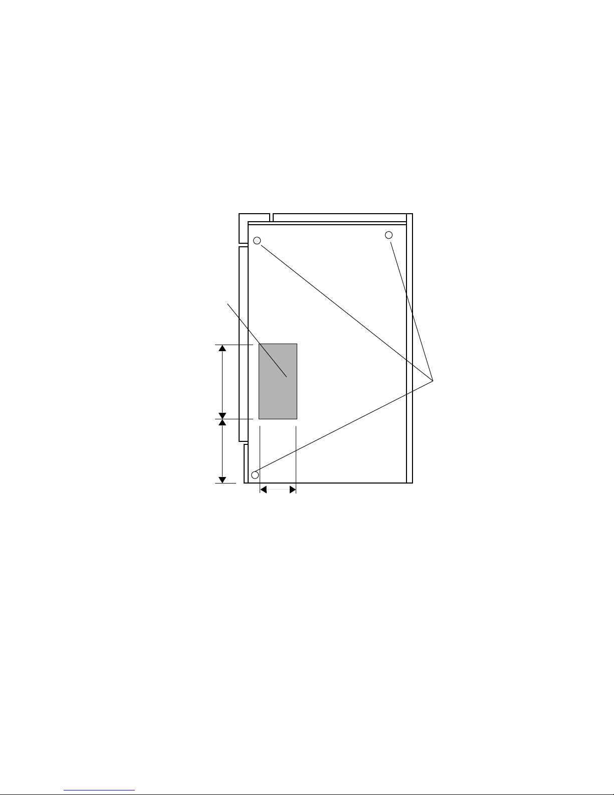
entry for the UPS cabinet can be accommodated through the right-side panel (Figure 2–1)
or by use of the UPS Auxiliary Cabinet or the UPS CSA Cabinet.
TOP
FRONT
BACK
REMOVABLE COVER PLATE
SIDE CABLE ENTRY AREA
419 mm
(16.50 in)
191 mm
(7.5 in)
229 mm
(9.00 in)
RIGHT-SIDE VIEW OF UPS
Figure 2–1 Right-Side Cable Access for the UPS Cabinet
MOUNTING HOLES
(3 PLACES)
MKV-A2200-91
SITE PREPARATION 2–3
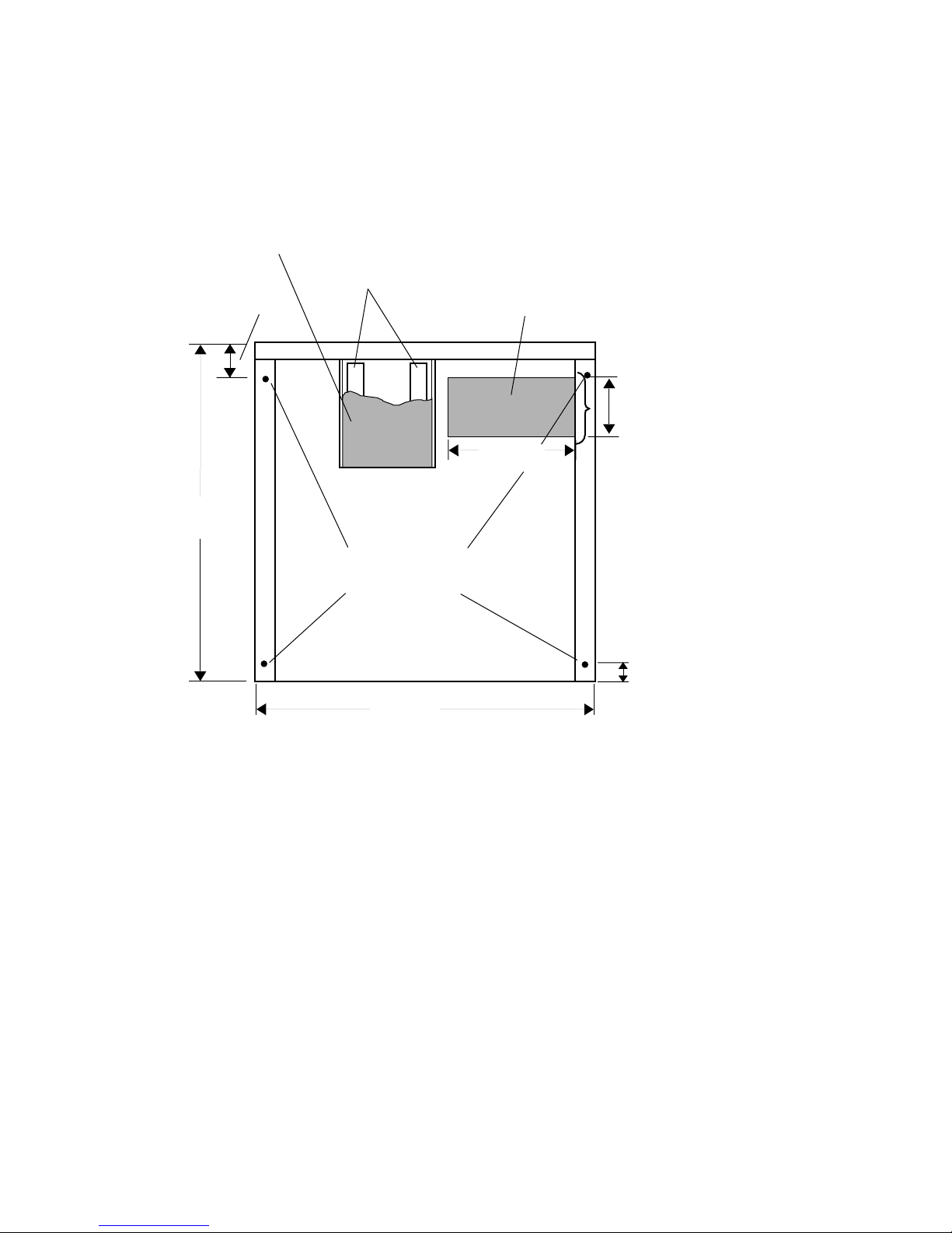
The designated bottom cable entry area for the UPS cabinet is shown in Figure 2–2 for
models rated 20 and 40 kVA, and in Figure 2–3 for models rated 60 and 80 kVA.
FRONT
DRAW-OUT AIR FILTER
(REMOVE DURING SHIPPING)
817 mm
(32.18 in)
86.4 mm
(3.40 in)
AIR INTAKE
REMOVABLE COVER PLATE
BOTTOM CABLE ENTRY AREA
200 mm
(7.88 in)
220 mm
(8.66 in)
MOUNTING HOLES
9 mm DIAMETER (0.375 in)
4 PLACES
50.8 mm
(2.00 in)
800 mm
(31.5 in)
BACK
BOTTOM VIEW LOOKING UP
Figure 2–2 Bottom View, 20 and 40 kVA Models
MKV-A2201-91
2–4 SITE PREPARATION
DRAW-OUT AIR FILTER
(REMOVE DURING SHIPPING)
86.4 mm
(3.40 in)
FRONT
AIR INTAKE
REMOVABLE COVER PLATE
BOTTOM CABLE ENTRY AREA
200 mm
(7.88 in)
356 mm
(14 in)
817 mm
(32.18 in)
MOUNTING HOLES
9 mm DIAMETER (0.375 in)
4 PLACES
50.8 mm
(2.00 in)
800 mm
(31.5 in)
BACK
BOTTOM VIEW LOOKING UP
MKV-A2202-91
Figure 2–3 Bottom View, 60 and 80 kVA Models
For UPS equipment installed on a raised computer room floor, two floor through-holes
should be provided beneath the enclosure. One is for cabling and the other serves as an
air inlet for the cooling air required by the UPS. See Figure 2–2 or Figure 2–3 for the
location of these holes for your UPS.
NOTES
For nonraised floor installations, the area under the draw-out air filter must be
kept clear of obstructions for filter installation and servicing.
The UPS dissipates heat and exhausts warm air through the top portion of the enclosure.
Refer to Table 2–1 for heat dissipated (Btu/Hr). Air exhaust for models rated 20 and 40
kVA is 1200 cubic feet per minute (CFM). Air exhaust for models rated 60 and 80 kVA is
1600 CFM.

SITE PREPARATION 2–5
Table 2–1 also lists the weight and dimensions of the HA32A UPS cabinets.
Table 2–1 Standard HA32A UPS Models
Nominal
Model
Number
HA32A-AH 20/16 208 80 208Y/120 800/31.5 488/1,075 8,189
HA32A-DH 20/16 220 80 220Y/127 800/31.5 488/1,075 8,189
HA32A-BH 20/16 480 40 208Y/120 800/31.5 488/1,075 8,189
HA32A-CH 20/16 480 40 480Y/277 800/31.5 488/1,075 8,189
HA32A-AK 40/32 208 175 208Y/120 800/31.5 628/1,385 15,013
HA32A-DK 40/32 220 175 220Y/127 800/31.5 628/1,385 15,013
HA32A-BK 40/32 480 80 208Y/120 800/31.5 628/1,385 15,013
HA32A-CK 40/32 480 80 480Y/277 800/31.5 628/1,385 15,013
HA32A-AM 60/48 208 250 208Y/120 1,143/45.0 783/1,725 20,130
HA32A-DM 60/48 220 250 220Y/127 1,143/45.0 783/1,725 20,130
HA32A-BM 60/48 480 100 208Y/120 1,143/45.0 783/1,725 20,130
HA32A-CM 60/48 480 100 480Y/277 1,143/45.0 783/1,725 20,130
Rating
kVA/kW
Output
Input
Voltage
(Volts)
3
Input
CB
Rating
(Amps)
Output
Voltage
(Volts)
3
Width
mm/in
Approx.
Weight
kg/lbs
Loss
(Full
Load)
Btu/Hr
Heat
HA32A-AN 80/64 208 350 208Y/120 1,143/45.0 1,023/2,250 26,954
HA32A-DN 80/64 220 350 220Y/127 1,143/45.0 1,023/2,250 26,954
HA32A-BN 80/64 480 150 208Y/120 1,143/45.0 1,023/2,250 26,954
HA32A-CN 80/64 480 150 480Y/277 1,143/45.0 1,023/2,250 26,954
Height of all models: 1,402 mm/55.18 in.
Depth of all models: 817 mm/32.18 in.
The HA32A UPS cabinet is a standalone enclosure. The HA32B UPS Battery Cabinet is
a standalone enclosure. The HA32C/D/E UPS Auxiliary Cabinet, when used, attaches to
the right side of the HA32A UPS cabinet. The HA33D/F UPS CSA Cabinet, when used,
attaches to the right side of the HA32A UPS cabinet or the right side of the HA32C/D/E
UPS Auxiliary Cabinet. The HA32J/K UPS Distribution Cabinet, when used, attaches
to the right side of the HA32A UPS cabinet, the right side of the HA32C/D/E UPS
Auxiliary Cabinet, or the right side of the HA33D/F UPS CSA Cabinet. Refer to the
HA32B, HA32C/D/E, HA33D/F, and HA32J/K installation information before performing
the HA32A UPS cabinet installation.
2–6 SITE PREPARATION
2.4 HA32B UPS BATTERY CABINET
Before installation of the UPS Battery Cabinet, consideration must be given to the
environmental and the structural integrity of its intended location. The electrical wiring
must meet both local and national electrical codes.
2.4.1 Environmental Considerations
• Air Temperature: The recommended operating temperature is 25°C (77°F).
The UPS Battery Cabinet adds an insignificant amount of heat to the environment
when fully charged, and normally is not calculated when sizing the capacity of an air
conditioner.
• Air Quality: The UPS Battery Cabinet should be provided with air free of
contaminants such as excessive moisture, vapor, flammable gases, chemical fumes,
salt, or excessive dirt and dust.
• Ventilation: The UPS Battery Cabinet is designed for operation on a raised
computer room floor or a concrete floor. Cooling air for the UPS Battery Cabinet
is typically provided through a perforated floor tile on a computer room floor. Cutouts
are necessary for bottom access cables only.
• Humidity: 10 to 90%, noncondensing.
• Altitude: Sea level to 2,134 meters (7,000 feet).
2.4.2 Mechanical Considerations
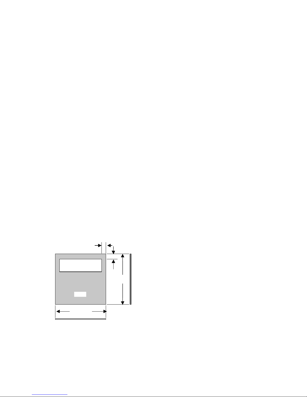
• Floor Tile Cutout: A floor tile cutout is required to provide bottom cable entry to
the UPS Battery Cabinet. When the UPS Battery Cabinet is installed on a raised
computer floor, its weight should be evenly distributed. Locate the corners of the UPS
Battery Cabinet as close as possible to the corners of the tiles. Figure 2–4 gives the
nominal dimensions and location for this cutout.
2 INCH (TYPICAL)
2.5 INCH
6 INCH BY 20 INCH
CUT OUT
24 INCH
(REF)
TILE
TILE FRONT
24 INCH
(REF)
Figure 2–4 Floor Tile Cutout
MKV-A2203-91

SITE PREPARATION 2–7
• Floor Loading: The weight of the UPS Battery Cabinet must be considered when
planning the equipment or computer room layout. The floor must be capable
of supporting the weight of the UPS Battery Cabinet, as well as all associated
equipment (UPS, air conditioning system, furniture, and so forth.) as oriented on
your equipment or computer room layout. Particular attention to weight must be
given when the equipment is installed on a floor raised above ground level. The
approximate weight and dimensions of the UPS Battery Cabinets are listed in
Table 2–2.
• Service Area: The UPS Battery Cabinet requires rear, top, and front access for
servicing. At least 610 mm (24 in.) at the rear of the unit should be allowed for
service. At least 914 mm (36 in.) of clearance above the unit should be allowed for
normal ventilation. At least 1,219 mm (48 in.) in front of the unit should be allowed
for service. This will provide sufficient area to allow the pull-out rack assembly to be
removed from the unit.
Table 2–2 UPS Battery Cabinet Model Numbers
Circuit
Model
Number
kVA
Rating
Nominal
Protection
in Minutes
Breaker
(QF1)
Rating in
Amperes
Width of
Battery
Cabinet
(mm/in)
Approx.
Installed
Weight
(kg/lbs)
HA32B-AH 20 5 90 800/31.5 530/1,169
HA32B-CH 20 15 90 800/31.5 530/1,169
HA32B-FH 20 30 90 1,143/45.0 905/1,995
HA32B-AK 40 5 125 800/31.5 530/1,169
HA32B-CK 40 14 125 1,143/45.0 905/1,995
HA32B-FK
1
40 30 125 2 x 1,143/45.0 2 x 826/1,820
HA32B-AM 60 5 175 1,143/45.0 905/1,995
HA32B-CM
HA32B-FM
1
60 10 175 2 x 1,143/45.0 2 x 826/1,820
1
60 30 175 2 x 1,143/45.0 2 x 826/1,820
HA32B-AN 80 5 225 1,143/45.0 905/1,995
HA32B-CN
HA32B-FN
1
Consists of two battery cabinets with same dimensions and weight.
1
80 14 225 2 x 1,143/45.0 2 x 826/1,820
1
80 22 225 2 x 1,143/45.0 2 x 905/1,995
Height of all models: 1,402 mm/55.18 in.
Depth of all models: 817 mm/32.18 in.
2–8 SITE PREPARATION
2.5 HA32C/D/E UPS AUXILIARY CABINET
The HA32C/D/E UPS Auxiliary Cabinet is designed to attach to the right side of the
HA32A UPS cabinet (Figure 2–5). The weight and dimensions of the UPS Auxiliary
Cabinets are listed in Table 2–3.
NOTE
The side panels are not provided with the UPS Auxiliary Cabinet. The right
side panel of the UPS cabinet must be removed and attached to the right side of
the UPS Auxiliary Cabinet after installation.
UNINTERRUPTIBLE
HA32A
POWER
SYSTEM
HA32C/D/E
UPS
AUXILIARY
CABINET
MKV-A2204-91
Figure 2–5 UPS Auxiliary Cabinet Placement

Table 2–3 UPS Auxiliary Cabinet Weights and Dimensions
HA32D-XX
Output
Rating
(kVA)
Isolation
Transformer
Only
(kg/lbs)
HA32E-PX
Input Current
Filter Only
(kg/lbs)
20 204/450 154/341 268/591
40 249/550 169/374 328/724
60 327/720 214/473 450/993
80 386/850 260/573 556/1,255
Height of all models: 1,402 mm/55.18 in.
Width of all models: 477 mm/18.78 in.
Depth of all models: 817 mm/32.18 in.
HA32C-XX
Isolation Transformer
and Input Current Filter
(kg/lbs)
SITE PREPARATION 2–9
 Loading...