

Digital Equipment DIGITAL Server 7100 1200, FR-932WW-CX, FR-932WW-CA, FR-932WW-CB Service Maintenance Manual

DIGITAL Server 3100/3200
DIGITAL
Serve
r7100
DIGITAL Server 7100 Series
Service Maintenance Manual
Part Number: ER-932WW-SM. A01
Digital Equipment Corporation

January 1998
The information in this document is subject to change without notice and should not
be construed as a commitment by Digital Equipment Corporation.
Digital Equipment Corporation assumes no responsibility for any errors that might
appear in this document.
The software, if any, described in this document is furnished under a license and may
be used or copied only in accordance with the terms of such license. No responsibility
is assumed for the use or reliability of software or equipment that is not supplied by
Digital Equipment Corporation or its affiliated companies.
Restricted Rights: Use, duplication, or disclosure by the U.S. Government is subject
to restrictions as set forth in subparagraph (c) (1) (ii) of the Rights in Technical Data
and Computer Software clause at DFARS 252.227-7013.
DIGITAL Se r ve r 7100 Series Service Maintenance Manual
1998 Digital Equipment Corporation.
All Rights Reserved.
AMI is a registered trademark of American Megatrends, Inc.
DEC, D IGITAL , S e rv e rWOR KS , and the DIGITAL logo are trademarks of Digital
Equipment Corporation.
Intel and Pentium are registered trademarks of Intel Corporation.
Micros o ft, Windows NT, and Windows 95 are registered trademarks of Microsoft
Corporation.
Novell and NetWare are U.S. registered trademarks of Novell Inc.
OS/2 and PS/2 are registered trademarks of International Business Machines
Corporation.
SCO is a trademark of The Santa Cruz Operation, Inc.
SCSI
Select
is a registered trademark of Adaptec Corporation.
UNIX is a registered trademark of X/Open Company, Ltd.
All other trademarks and registered trademarks are the property of their respective
holders.

DIGITAL Server 3100/3200
DIGITAL
Serve
r7100
FCC ID: 9 3 X WW1
The FCC wa nt s y ou to k now...
This equipment has been tested and found to comply with the limits for a Class B
digital device, pursuant to Part 15 of the FCC rules. These limits are designed to
provide reasonable protection against harmful interference in a residential installation.
Any changes or modifications made to this equipment may void the user's authority
to operate this equipment.
This equipment generates, uses, and can radiate radio frequency energy and, if not
installed and used in accordance with the instructions, may cause harmful
interference to radio communications. However, there is no guarantee that
interference will not occur in a particular installation. If this equipment does cause
harmful interference to radio or television reception, which can be determined by
turning the equipment off and on, the user is encouraged to try to correct the
interference by one or more of the following measures:
• Reorient or relocate the receiving antenna
• Increase the separation between the equipment and receiver
• Connect the equipment into an outlet on a circuit different from that to which
the receiver is connected
• Consult the dealer or an experienced radio/TV technician for help
All external cables connecting to this basic unit need to be shielded. For cables
connecting to option cards, see the option manual or installation instructions.
This digital apparatus does not exceed the Class B limits for radio noise emissions
set out in the radio interference regulations of the Canadian Department of
Communications.

This equipment is in the 2nd Class category (information equipment to be used in a
residential area or an adjacent area thereto) and conforms to the standards set by
the Voluntary Control Council For Interference by Data Processing Equipment and
Electronic Office Machines aimed at preventing radio interference in such residential
area.
When used near a radio or TV receiver, it may become the cause of radio
interference.
Read the instructions for correct handling.
This equipment meets or exceeds requirements for safety in the U.S. (UL 1950),
Canada (CSA C22.2 No. 950), and Europe (EN 60950/IEC 950) with Nordic
requirements.
This equipment meets or exceeds the ergonomic requirements of ZH1/618 and is
certified to bear the GS mark by TUV Rheinland of Germany.
This equipment has been tested for radio frequency emissions and has been verified
to meet VDE 0871 Class B.

i
DIGITAL Server 3100/3200
DIGITAL
Serve
r7100
Contents
Preface.............................................................................................................. vii
1
Product Description
System Introduction......................................................................................... 1-1
Reliability/Availability........................................................................................ 1-2
Server Expansion............................................................................................ 1-3
Server Management and Security.................................................................... 1-4
Server Configurations...................................................................................... 1-5
Server Naming Guidelines........................................................................ 1-5
Product Model Numbering Convention...................................................... 1-6
Related Material.............................................................................................. 1-8
Latest Product Information and Updates.......................................................... 1-10
Enterprise Server Product Information...................................................... 1-10
Updates.................................................................................................... 1-10
2
Server Software and Utilities
Introduction..................................................................................................... 2-1
ServerWORKS Quick Launch.......................................................................... 2-2
Creating Diskettes and Viewing On-line Documentation............................ 2-2
System Configuration Utility (SCU) .................................................................. 2-2
When to Run the SCU.............................................................................. 2-3
Configuring Expansion Boards.................................................................. 2-3
Starting the SCU ...................................................................................... 2-4
Using the SCU.......................................................................................... 2-6
SCU Keyboard Function Keys................................................................... 2-7
Configure Computer................................................................................. 2-7
Setting the Date and Time........................................................................ 2-8
Maintain System Configuration Diskette.................................................... 2-8

Contents
ii
RAID Configuration Utility................................................................................ 2-9
BIOS Upgrade Utility ....................................................................................... 2-9
SCSI
Select
Utility............................................................................................ 2-10
Diagnostics ..................................................................................................... 2-11
3
SCU Features
Introduction..................................................................................................... 3-1
System - DIGITAL Server 7100 ................................................................ 3-2
System Management Group..................................................................... 3-3
Diskette Drive Group................................................................................ 3-4
Boot Options Group.................................................................................. 3-5
Integrated Peripherals Group.................................................................... 3-6
Keyboard Features Group ........................................................................ 3-7
Shadow Options Group ............................................................................ 3-8
Security Options Group ............................................................................ 3-9
Cache Options Group............................................................................... 3-10
Advanced Control Group .......................................................................... 3-10
EISA or PCI Devices Group...................................................................... 3-12
4
Troubleshooting
Introduction..................................................................................................... 4-1
Initial Troubleshooting...................................................................................... 4-2
Diagnostics ..................................................................................................... 4-3
Running the Diagnostics........................................................................... 4-4
Running Quick Tests or Groups of Tests................................................... 4-4
Running DIGITAL Vendor Extended Tests................................................ 4-5
Running Diagnostics Tests from the Hard Disk Drive................................. 4-5
Obtaining Information about the Server ........................................................... 4-6
Obtaining Information Using the SCU........................................................ 4-8
Obtaining Information Using Server Management Software....................... 4-8
Displaying Server Status Using the Hardware........................................... 4-9
Server Status Messages ................................................................................. 4-10
POST OCP Messages..................................................................................... 4-12
POST Codes............................................................................................ 4-12
Boot Codes .............................................................................................. 4-13
OCP Messages............................................................................................... 4-14
OCP Status and Error Messages.............................................................. 4-15

Contents
iii
DIGITAL Server 3100/3200
DIGITAL
Serve
r7100
Server Processor Voltage and Temperature Ranges ....................................... 4-17
Processor Voltage Range......................................................................... 4-17
VRM Voltage Range................................................................................. 4-18
Processor Temperature Warning Levels ................................................... 4-18
Advanced Troubleshooting.............................................................................. 4-19
Server Troubleshooting ................................................................................... 4-20
Disk Drive Troubleshooting.............................................................................. 4-24
SBB Troubleshooting....................................................................................... 4-27
Tape Drive Troubleshooting............................................................................. 4-27
Monitor Troubleshooting.................................................................................. 4-28
CD-ROM Troubleshooting ............................................................................... 4-29
Diskette Drive Troubleshooting........................................................................ 4-30
RAID Troubleshooting ..................................................................................... 4-31
Wide Ultra SCSI Bus Repeater Module Troubleshooting.................................. 4-32
5
FRU Replacement
Introduction..................................................................................................... 5-1
Server Front View............................................................................................ 5-2
Server Left-Side View...................................................................................... 5-4
Server Right-Side/Rear View........................................................................... 5-6
Miscellaneous ................................................................................................. 5-8
Labels and Nameplates................................................................................... 5-8
Service Procedures......................................................................................... 5-9
Recommended Tools ...................................................................................... 5-9
Special Tools Required.................................................................................... 5-9
Other Materials Needed .................................................................................. 5-10
Remedial Diagnostic Test Software ................................................................. 5-10
Virus Software Information .............................................................................. 5-10
BIOS Version Information................................................................................ 5-10
Disconnecting External Devices and Power ..................................................... 5-11
Removing and Installing the Side Panels ......................................................... 5-12
Server Front View............................................................................................ 5-15
Server Left Side View...................................................................................... 5-17
Server Right Side View.................................................................................... 5-19
Server Rear View............................................................................................ 5-21
Main Logic Board Connectors.......................................................................... 5-23
Main Logic Board Components........................................................................ 5-25
Processor Module Components and Connectors ............................................. 5-27
Wide Ultra SCSI Bus Repeater Module Layout ................................................ 5-29
Main Logic Board Switch Settings.................................................................... 5-31

Contents
iv
Processor Module Switch Settings............................................................ 5-34
Installing Additional Memory............................................................................ 5-36
Supported DIMM Upgrade Kits................................................................. 5-37
Memory Configuration Guidelines............................................................. 5-37
Memory Troubleshooting.......................................................................... 5-41
Removing and Replacing the Power Supply..................................................... 5-42
Removing and Replacing the Diskette Drive..................................................... 5-44
Removing and Replacing the CD-ROM Drive................................................... 5-46
Removing and Replacing a Cooling Fan .......................................................... 5-48
Removing and Replacing the Secondary Cooling Fan 2.................................. 5-50
Removing and Replacing the Speaker............................................................. 5-52
Removing the Main Logic Board...................................................................... 5-54
Replacing the Main Logic Board ...................................................................... 5-56
Removing the Storage Backplane.................................................................... 5-56
Replacing the Storage Backplane.................................................................... 5-58
Removing and Replacing a Caster................................................................... 5-58
6
Processor Module Upgrades
Introduction..................................................................................................... 6-1
Configuration Guidelines.................................................................................. 6-2
Create Diskettes from the Quick Launch CD-ROM........................................... 6-2
Installing a Second Processor Module ............................................................. 6-3
Processor Compatibility in a Multiprocessor Environment................................. 6-7
Installing a Processor on a Processor Module.................................................. 6-7
Removing the Processor Module.............................................................. 6-8
Installing a Processor and Voltage Regulator Module (VRM)..................... 6-9
Run the System Configuration Utility (SCU) .............................................. 6-15
Update the BIOS............................................................................................. 6-16
Troubleshooting............................................................................................... 6-16
Using the Crisis Recovery Diskette if Necessary....................................... 6-16

Contents
v
DIGITAL Server 3100/3200
DIGITAL
Serve
r7100
7
Device Mapping
Introduction..................................................................................................... 7-1
Processor Memory Address Map.............................................................. 7-2
Processor I/O Address Map...................................................................... 7-2
I/O Address Map...................................................................................... 7-3
Server Interrupt Levels............................................................................. 7-3
DMA Channel Assignment........................................................................ 7-4
PCI Configuration Space Address Map..................................................... 7-4
A
Service Notes................................................................................................ A-1
Figures
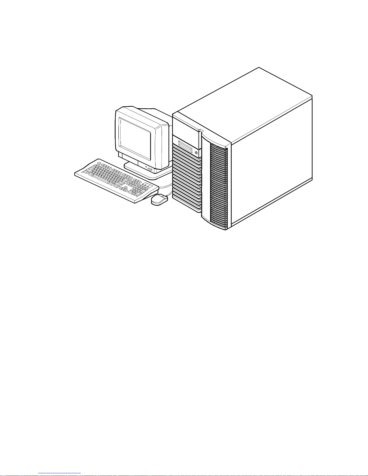
Typi ca l DIGITA L S e rv e r 7100............................................................................................ viii
2-1. SCU Main Menu Options........................................................................................... 2-5
4-1. DIGIT A L S e rv e r C o mponent Information.................................................................... 4-7
5-1. Se rv e r F ro n t V iew ...................................................................................................... 5-3
5-2. Se rv e r L e ft-S ide V i e w................................................................................................ 5-5
5-3. Se rv e r R ight-Side/R e a r V iew ..................................................................................... 5-7
5-4. Se rv e r B ra k e..............................................................................................................5-11
5-5. Unlocking and Removing the Side Panels................................................................. 5-13
5-6. Insta lling Sid e Covers................................................................................................. 5-14
5-7. Se rv e r F ro n t V iew ...................................................................................................... 5-16
5-8. Se rv e r L e ft S ide V i e w................................................................................................. 5 -18
5-9. Se rv e r R ight Side V i e w.............................................................................................. 5-20
5-10. S e rv e r R e a r V i e w..................................................................................................... 5-22
5-11. Main Logic Board Connectors.................................................................................. 5-24
5-12. Main Logic Board Components................................................................................ 5-26
5-13. Processor Module Components and Connectors ..................................................... 5-28
5-14. Wide Ultra SCSI Repeater Module Component Locations ...................................... 5-30
5-15. Main Logic Board Switch Location............................................................................ 5-33
5-16. Processor Module Switch Location.......................................................................... 5-35
5-17. D IMM Bank L o ca tions.............................................................................................. 5-38
5-18. Removing and Replacing the Power Supply............................................................ 5-43
5-19. Removing and Replacing the Diskette Drive............................................................ 5-45
5-20. Removing and Replacing the CD-ROM Drive.......................................................... 5-47
5-21. Removing and Replacing a Cooling Fan.................................................................. 5-49
5-22. Removing and Replacing the Secondary Cooling Fan 2........................................... 5-51

Contents
vi
5-23. Removing and Replacing the Speaker...................................................................... 5-53
5-24. Removing and Replacing the Main Logic Board....................................................... 5-55
5-25. Removing and Replacing the Storage Backplane..................................................... 5-57
5-26. Removing and Replacing a Caster ........................................................................... 5-59
6-1. Re mo v i n g th e Termin a to r C a rd.................................................................................. 6-4
6-2. Installing a Processor Module.................................................................................... 6-6
6-3. Removing the Processor Module............................................................................... 6-8
6-4. Removing the Retaining Clip...................................................................................... 6-9
6-5. Re mo v i n g th e Proces s o r/H e a t S ink Assembl y ........................................................... 6 -1 0
6-6. Insta lling the N e w Proce s s o r...................................................................................... 6-11
6-7. Installing the Retaining Clip........................................................................................ 6-12
6-8. Insta lling a VR M......................................................................................................... 6-13
6-9. Installing the Processor Module................................................................................. 6-14

vii
DIGITAL Server 3100/3200
DIGITAL
Serve
r7100
Preface
P
This
Service Maintenance Manual
is a troubleshooting guide that can be used for
reference when servicing DIGITAL Serve rs .
DIGITAL re s e rve s th e r ight to make changes to this
Service Maintenance Manual
without notice. Accordingly, the illustrations and procedures in this document might
not apply to all DIGITAL Servers to b e s e rv i ce d s i n ce m a n y o f th e diagnostic tests
are designed to test more than one product.
CAUTION:
DIGITAL recomm ends t hat only A+/DIGITAL
Server certified engineers at t em pt to repair this equipment.
All troubleshooting and repair procedures are det ailed to
support subassembly/module level exchange. Because of the
complexity of the individual boards and subassemblies, no
one should attempt t o m ake r epairs at the component level or
make modifications to any printed circuit boar d. Improper
repairs can create a safet y hazar d. Any indications of
component replacement or cir cuit board modifications might
void any warranty or exchange allowances.
Preface
viii
DEC00421
Typical D IGITA L S erver 7100

1-1
DIGITAL Server 3100/3200
DIGITAL
Serve
r7100
1
Product Description
1
System Introduction
The DIGITA L Se r ve r 7100 is a high-performance, highly-scaleable network and
enterprise server featuring the latest in modular processor and storage technology.
The DIGITA L Se r ve r p r o v ides support for the following features:
Reliabilit y /A v a ila bilit y
Pentium Pro Processor
Module
Up to four SMP Pentium Pro processors, each with an
integrated 512 KB, four way set-associative, write-back
cache.
Error Correction Code
(ECC) Memory
Maximum expandability with up to 4 GB of ECC protected
DIMM memory.
Dual-Channel Storage
Backplane
Redundant disk subsystems using dual-channel wide Ultra
SCSI or wide Ultra RAID adapters.
Power Supplies
The DIGITA L Se r ve r 7100 ships with two 450 W power
supplies for normal operation. In some configurations, the
second power supply can be used for redundant
operation.
Variable Fan Speed
Automatically adjusts fan speed according to ambient
temperature.
Internal Sensors
Monitors internal server temperatures, fan operation, and
power supply temperatures and voltages.

Product Description
1-2
Server Ex pansion
Flexible Memory
Architecture
Two memory modules provide a 4-way interleaved
memory system, with 128 MB (4 x 32 MB) of minimum
supported memory and 4 GB (16 x 256 MB) of maximum
supported memory.
12 I/O Expansion Slots
Seven PCI expansion slots, four EISA slots, and one
shared EISA/PCI slot. Dual peer PCI bus design with
peak bandwidth of 264 MB/sec PCI-to-EISA bridge.
Integrated SVGA Video
Controller
Supports management and configuration applications
locally (on the main logic board) without use of an
expansion slot.
Adaptec 3940UW Wide
Ultra
SCSI or RAID
Adapter
Support for narrow and internal wide Ultra SCSI devices.
Capacity for 10 internal
SCSI Storage Devices
Accommodates seven 3½-inch half-height drives in
Storage Building Blocks (SBBs), two 5¼-inch, half-height
drives (hard drives or tape drives), and one CD-ROM
drive.
External I/O Ports
Two serial ports and one parallel port to support external
options such as a printer, modem, or local terminal.
Wide Ultra SCSI Storage
Backplane
Supports high-performance drives for single or dual
channel wide Ultra SCSI and wide Ultra RAID
configurations.
Disk Hot Swap Capability
Allows replacement of SBB disk drives while the server is
operating.
Clusters
Supports DIGITAL Clusters for Windows NT and Microsoft
Cluster Server (part of Microsoft Windows NT Server,
Enterprise Edition) for database and file services failover.

Product Description
1-3
DIGITAL Server 3100/3200
DIGITAL
Serve
r7100
Server Management and Security
Server Diagnostics
Allows local and remote diagnosis of server problems.
Hardware Configuration
Allows local and remote server configuration.
Unique Asset
Management
Unique server identifier in non-volatile memory provides
easy asset management.
Firmware Upgrade Utility
Upgrades firmware versions.
Operator Control Panel
(OCP)
Back-lit, 16-character display for diagnostic and error
messages.
Hard Drive Indicator
Lights
Provides immediate status information on SBB hard drive
activity or failure.
Key Lock
Limits access to server components.
Interlock Sensor
Switches
Automatically turns off server power if either side panel is
removed when the server power is on.

Product Description
1-4
Server Configurations
The following rules apply when
Product Fa m ily Names
and
Product Mode l Names
are assigned to DIGITAL Server p r oducts. These rules apply to all products
developed in the NT Server Business Unit (NTSBU).
Server Naming Guidelines
•
All products in a family carry the same name on the nameplate. (i.e. all
products in the Entry space will carry the name DIGITAL SERV ER 1000)
Family Name Segment
DIGITAL SER V ER 500
SUB ENTRY
DIGITAL SER V ER 1000
ENTRY
DIGITAL SER V ER 3000
DEPARTMENT
DIGITAL SER V ER 5000
APPLICATION
DIGITAL SER V ER 7000
ENTERPRISE
DIGITAL SER V ER 9000
SUPER ENTERPRISE
•
Products in a rackmount chassis will have an R after the Family Name
(DIGITAL S e rve r 3000R).
•
Product models within a family will be differentiated by the Product Model
Name. The Product Model Name will appear on a label on the rear of the
product. Specific configurations within a model will carry the same Product
Model Name and will be differentiated by the part number.

Product Description
1-5
DIGITAL Server 3100/3200
DIGITAL
Serve
r7100
Product Model Numbering Convention
The following example describes the product model numbering convention:
DIGITAL SER V ER 1234 5678A R
1 = PRODUCT FAMILY NAME (first character of family number)
2 = MAJOR PROCESSOR TECHNOLOGY DIFFERENTIATOR WITH IN TH E
FAMILY
This number will be assigned to each new platform based on the following matrix.
Open numbers will be assigned as new processor technology is introduced. THIS
FIELD IS NOT USED FOR SUB ENTRY PRODUCTS.
100 = Pentium Pro
200 = Pentium II – Slot 1
300 = EV5
400 = Pentium II – Slot 2
500 = EV6
600 = OPEN
700 = OPEN
800 = OPEN
900 = OPEN
3,4 = USED TO D IFFERE N TIATE MODE LS BASED UP ON DIFFER EN T
PROCESSORS WITHIN A PROCESSOR TECHNOLOGY (I.E. CLOCK SPEED,
CACHE SIZE) START AT 00 FOR FIRST MODEL AND INCREMENT BY 05 FOR
EACH A D D ITION AL M OD EL .

Product Description
1-6
5 = CPU TYPE
BLANK = PENTIUM
1= PENTIUM PRO
2 = PENTIU M II/SL OT 1
3 = PENTIU M II/SL OT 2
4 = Open/Available for future processors
5 = Open/Available for future processors
6 = ALPHA EV56
7 = ALPHA PCA57
8 = ALPHA EV6
9 = ALPHA EV67
6, 7, 8,9 = CPU CLOCK SPEED IN MHZ

Product Description
1-7
DIGITAL Server 3100/3200
DIGITAL
Serve
r7100
Related Material
The following related material is available:
Document or Software Title Order Number Description
Service Quick Reference ER-932WW-SR (English only) Provides troubleshooting
information that can be used when
servicing DIGITAL servers. This
manual is a condensed version of
the Service Maintenance Manual
and is provided in a pocket-size
format (4 x 8-inches).
Installation Guide ER-932WW-IM (Multilanguage)*
ER-932WW-IJ (Japanese)
Provides information on connecting
hardware cables and booting the
server. This guide also explains
how to use DIGITAL
ServerWORKS Quick Launch to
install an operating system, create
driver and utility diskettes, and
view on-line help and support
documentation.
System Reference ER-932WW-UA (English)
ER-932WW-UJ (Japanese)
Provides information on using the
server’s configuration utilities,
installing peripherals and options,
security, and troubleshooting. The
System Reference is available on
the Quick Launch CD-ROM in
English, Spanish, German, Italian,
and French.
Quick Reference labels 36-47812-03 (left side panel)
36-47812-04 (right side panel)
Provides an overview of major server
components, configuration guidelines,
and SCSI cabling information. These
labels are located on the inside of the
server’s side panels.
Warranty and Service Information ER-PCWAR-CM
(Multilanguage)*
Provides warranty information and
a listing of phone numbers for
technical support.
* Multilanguage includes: English, French, Italian, German, and Spanish
continued

Product Description
1-8
Document or Software Title Order Number Description
DIGITAL ServerWORKS software QB-4WY9A-SA
(Multilanguage)*
Contains ServerWORKS Quick
Launch and ServerWORKS
Manager software and
documentation.
Quick Launch consists of a bootable
CD-ROM disc and Getting Started
guide. This program steps the user
through the initial server setup and
operating system installa tion.
ServerWORKS Manager consists of
two CD-ROMs and an Overview and
Installation Guide and supporting
documentation.
Product README and Revision
History Information - Quick
Launch CD-ROM
Refer to the Quick Launch
CDROM in the DIGITAL
ServerWORKS software kit.
Provides additional product
information and product change
history.
Option documentation - Quick
Launch CD-ROM
Refer to the Quick Launch
CDROM in the DIGITAL
ServerWORKS software kit.
Provides postscript files that can be
viewed and printed using Adobe
Acrobat Reader software. These
files are provided in PDF format on
the Quick Launch CD-ROM
Diagnostic Software - Quick
Launch CD-ROM
Refer to the Quick Launch
CDROM in the DIGITAL
ServerWORKS software kit.
Contains an advanced set of
diagnostic utilities for identifying and
correcting problems on the server.
The diagnostic software can be used
to verify proper hardware installation
and isolate intermittent problems that
are not detected by the Power On
Self Test (POST). Refer to chapter
2 for information on using the
diagnostic utilities.
PC Product Support Information
Kit
QA-5RJAA-G8 (English only) Provides all the latest product
documentation for all NTSBU mobile,
desktop, and server products.
* Multilanguage includes: English, French, Italian, German, and Spanish
NOTE:
Refer to Chapter 2 f or pr ocedur es on how t o cr eat e
diskettes and view docum entation from the Quick Launc h CDRO M .

Product Description
1-9
DIGITAL Server 3100/3200
DIGITAL
Serve
r7100
Latest Product Information and Updates
Listed below is the current product information and update source locations.
Enterprise Server Product Information
Family Name Model Name Part Number Description Prioris Family
Name
DIGITAL Server
7000
DIGITAL Server
7100 1200
FR-932WW-CX 6200/512 (PP) -
KERNAL
N/A
DIGITAL Server
7000
DIGITAL Server
7100 1200
FR-932WW-CA 6200/512 (PP) -
MODEL 1
N/A
DIGITAL Server
7000
DIGITAL Server
7100 1200
FR-932WW-CB 6200/512 (PP) -
RAID
N/A
PowerGrade Chip
Upgrade
DIGITAL Server
7000 PowerGrade
Kit
FR-PC93U-AD 6200/512 (PP)
PowerGrade Chip
Upgrade
Prioris ZX 6000
Series
PowerGrade
PowerGrade Board
Upgrade with
2 processors
DIGITAL Server
7000 PowerGrade
Kit
FR-PC93U-AB 6200/512 (PP)
PowerGrade
Board Upgrade
Prioris ZX 6000
Series
PowerGrade
Updates
Current server utilities and technical support information is available on the Quick
Launch CD-ROM disc and the Internet.
For product information, use the address:
http://www.windows.digital.com
For technical support, use the address:
http://www.windows.digital.com/support/support.asp
For access directly to the software library for BIOS and driver updates, use the
address:
http://www.windows.digital.com/~ftp/00-index.stm

2-1
DIGITAL Server 3100/3200
DIGITAL
Serve
r7100
2
Server Software and Utilities
2
Introduction
This chapter describes the utilities supplied with the server. Server utilities include:
•
ServerWORKS Quick Launch This software is used to install a network
operating system onto the server. The CD-ROM also contains various
drivers and on-line documentation.
•
System Configuration Utility (SCU) This utility is available to configure the
server when relocating, adding, or removing EISA/ISA/PCI expansion
boards and when changing the server’s factory-defined settings. The SCU is
available on the Quick Launch CD-ROM.
•
RAID Configuration Utility This utility is available for RAID-ready servers
only. This utility is available to configure the RAID array. The RAID
configuration utility is available on the Quick Launch CD-ROM.
•
BIOS Upgrade Utility This utility is available to update or restore the
server’s BIOS. The BIOS Upgrade Utility is available on the Internet.
•
SCSI
Select
Utility This utility allows you to configure and view settings of
the onboard SCSI controller and SCSI devices. The SCSI
Select
Utility is
available each time you boot your server.
•
Diagnostics This utility is used to verify server operation. The diagnostics
utility is available on the Quick Launch CD-ROM.

Server Software and Utilities
2-2
ServerWORKS Quick Launch
ServerWORKS Quick Launch is used to install the server’s Network Operating
System (NOS). In addition to providing quick and seamless NOS installation, Quick
Launch also provides drivers, documentation, and the ability to make diskettes of
utilities such as diagnostics. For more information, refer to the
ServerWORKS Quick
Launch Getting Started
guide.
Creating Diskettes and Viewing On-line Documentation
Use the following procedure to create diskettes using the Quick Launch CD-ROM
and to view on-line product documentation.
1. Power on your server and boot the ServerWORKS Quick Launch CD-ROM.
2. Select the “User Documentation” button to view on-line product
documentation.
3. From the Quick Launch Main Screen, select the “Installations & Utilities”
button and then the Utility tab to create driver and utility diskettes.
4. Insert a DOS-formatted diskette into drive A, and choose the utility or driver
you wish to copy and select Continue.
5. Repeat this procedure for all the utilities and drivers you wish to copy.
System Configuration Utility (SCU)
The server was pre-configured at the factory using the System Configuration Utility
(SCU). This means that the server’s hardware (processor modules, memory, cache,
mass storage devices, expansion boards, etc.) has been identified and configured for
optimum performance. If you need to make changes to this configuration, DIGITAL
recommends that you use the SCU along with the information provided in this
section.
Refer to “Starting the SCU” described later in this chapter.
Refer to Appendix C, “SCU Features,” for more details about the SCU.
Refer to the ServerWORKS Quick Launch Getting Started guide and the README.TXT
file, which is located on the Quick Launch CD-ROM, for additional information.

Server Software and Utilities
2-3
DIGITAL Server 3100/3200
DIGITAL
Serve
r7100
When to Run the SCU
Always run the SCU each time you add, remove, or relocate ISA, PCI and/or EISA
expansion boards to reconfigure server resources (IRQs). You should also run the
SCU if the main logic board changed, after adding a processor module, or after
adding memory modules.
If the main logic board changes or a processor module is added, run the SCU (select
the option “Configure Computer”) to update the serial numbers of the components.
For more information on how to change the serial numbers, refer to Chapter 4,
“Obtaining Information About The Server.”
Typically, the server displays a message such as
Run SCU Utility.....Press
F1 to Continue
. Select how you want to access and run the SCU by following
the instructions displayed on the SCU screens.
Configuring Expansion Boards
Each time you add, remove, or relocate any EISA/ISA/PCI expansion board, you
need to run the SCU to identify their operating characteristics, server resource
requirements, and slot locations. Based on this information, the SCU will then
automatically assign the proper server resources to EISA expansion boards, enable
PCI boards, and inform you as to what jumper or switch settings need to be manually
set on ISA expansion boards to avoid resource conflicts.
The SCU identifies an expansion board’s operating characteristics and resource
requirements through Configuration (.CFG) files. These files contain main logic
board, EISA, PCI, and ISA expansion board vital characteristics and the server
resources they require for proper operation. Before you can configure the server,
you must copy the CFG files (and overlays if applicable) supplied with the additional
EISA expansion boards you installed to either the SCU directory on your hard disk
drive or the SCU diskette that you created earlier.
As an added feature, the SCU creates and stores all setup changes in a System
Configuration (.SCI) file. This file is automatically generated when you run the SCU.
Afterwards, this SCI file can be used on any DIGITAL Serv e r th a t i s identically
configured and can serve as a backup to the EISA configuration stored in NVRAM
memory.

Server Software and Utilities
2-4
Starting the SCU
The SCU is located on the ServerWORKS Quick Launch CD-ROM disk. The SCU
options are shown in Figure 2-1. If this is your first time using the SCU, it is
recommended that you select “Learn About Configuring your Computer” for detailed
information on using the SCU. If this is a subsequent session, refer to the
appropriate sections in this chapter to change the server’s configuration.
You can start the SCU in one of three ways:
1. During the Quick Launch boot process, if a DOS partition was created, the
SCU was copied to the partition on the hard disk drive. This allows you to
run the SCU anytime from the DOS partition.
At the MS-DOS prompt change to the SCU directory and type:
SCU.BAT
2. Creating a bootable SCU diskette by using the Quick Launch CD-ROM and
selecting the
Installations & Utilities
button and then the
Utilities
page. On
the
Utilities
page, select the appropriate BIOS level for the server that the
SCU is being created for (if this is being done on the server, the default
BIOS that is highlighted is the BIOS of that server)
.
Afterwards, you can run the SCU anytime by booting the diskette you
created.
3. You can also run the SCU by inserting the Quick Launch CD-ROM disk,
rebooting the server, and pressing and holding the right [ALT] key during the
boot process to display the SCU.
NOTE:
If EISA (in some cases, PCI) car ds have been added t o
the server , the SCU will be invoked automatically when you boot
from the Q uick Launch CD-ROM disc. The . SCI f ile is not saved
when you use this method to run t he SCU.
Server Software and Utilities
2-5
DIGITAL Server 3100/3200
DIGITAL
Serve
r7100
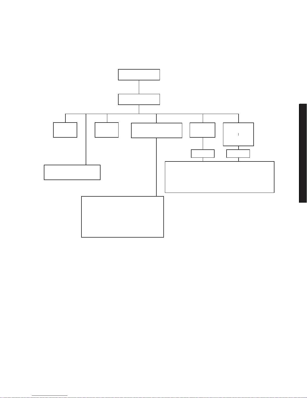
Welcome Screen
Main Menu
Set Date Set Time
Maintain System
Configuration Diskette
Configure
Computer
Configure
Computer
With System
Default
Learn About Configuring
Your Computer
See Note
See Note
Step 1: Important EISA Configuration Information
Step 2: Add or Remove Boards
Step 3: View or Edit Details
Step 4: Examine Switches or Print Report
Step 5: Save and Exit
Create a Backup SCI File
Load a Backup SCI File
Copy/Update CFG Files
Copy/Update SCI Files
Delete CFG Files
Delete SCI Files
Return to the Main Menu
DEC0045
6
Note:
If new boards are found, the following
message displays: The following changes have
automatically been made: [ Action: ]
Figure 2- 1 . SC U Ma in M e nu Options

Server Software and Utilities
2-6
Using the SCU
To use the SCU:
1. Turn on the server and allow the Power-On Self Test (POST) to complete.
If POST detects an error, take the appropriate steps to correct the problem.
After the problem has been resolved, restart the server.
2. Start the SCU using one of the three methods described previously.
3. Press [Enter] to display the SCU introductory screen.
NOTE:
The SCU contains help pop-up screens for any selected
menu item. Press [F1] at anyt im e t o display a help screen. Press
[Esc] to remove a help screen.
4. If no configuration errors appear, the Welcome screen displays.
Press [Enter] to display the Main menu.
If a configuration error appears, the Welcome screen displays information
about the error and tells you to reconfigure the server.
5. Step through the menu items to familiarize yourself with the SCU.

Server Software and Utilities
2-7
DIGITAL Server 3100/3200
DIGITAL
Serve
r7100
SCU Keyboard Function Keys
The following table lists the keyboard function keys used to scroll through the menu
screens, and select specific menu items in the SCU.
Keyboa r d K e y Function
[↓] Moves the cursor down one menu item.
[↑] Moves the cursor up one menu item.
[
→
] Moves the cursor one character to the right.
[
←
] Moves the cursor one character to the left.
[Enter] Displays the available user-selectable settings for the highlighted option or
selects the highlighted menu item.
[F6] View, change, or lock available resources for the highlighted option.
[F10] Press [F10] to complete a step.
[F1] Displays the selected menu item’s help screen.
[Esc] Returns the monitor screen to the previously selected menu item.
Configure Computer
This option provides step-by-step instructions on how to configure the server when
adding, removing, or relocating expansion boards and when changing operating
parameters.
Select one of the following menu options:
•
“Configure Computer with System Default” Loads the SCU default
settings.
•
“Configure Computer” Instructions are displayed. Complete the
instructions if you are performing an initial configuration on the server. If this
is a subsequent configuration, refer to the appropriate menu item to update
the server’s configuration.

Server Software and Utilities
2-8
Setting the Date and Time
Use these two SCU options to reset the date and time maintained by the server’s
battery.
To access this menu item:
1. Start the SCU using one of the three methods described in “Starting the
SCU.”
2. Press [Enter] to display the SCU main menu.
3. Configure the server for the current date and time by selecting the
Set Date
and
Set Time
options.
Maintain System Configuration Diskette
Select this option to maintain Configuration (CFG) files and System Configuration
Information (SCI) files.
To access this menu item:
1. Start the SCU using one of the three methods described in “Starting the
SCU.”
2. Press [Enter] to display the SCU main menu.
3. Select the
Maintain System Configuration Diskette
option, and
then press [Enter].
4. Select a menu item and complete the displayed instructions for that item.
Afterwards, the following menu options are available:
•
Create a backup SCI file
•
Load a backup SCI file
•
Copy/update CFG files
•
Copy/update SCI files
•
Delete CFG files
•
Delete SCI files
•
Return to the Main Menu

Server Software and Utilities
2-9
DIGITAL Server 3100/3200
DIGITAL
Serve
r7100
RAID Conf iguration U tility
RAID-ready DIGITAL Servers i n clude a RAID adapter and RAID configuration utility.
The RAID configuration utility appears when you boot the server with the
ServerWORKS Quick Launch CD-ROM disc. Use this utility to configure your RAID
array.
NOTE:
If you are configuring t he ser ver for Ultra SCSI, use the
DACCF utility f or the Mylex cont roller to enable Ultra SCSI dat a
transfers.
Refer to the RAID User’s Manual on the Quick Launch CD-ROM. Select the “User
Documentation” button.
BIOS Upgra de Ut ility
All servers have BIOS software in a flash (ROM) chip located on the main logic
board. This BIOS initializes hardware and boots the operating system when the
server is turned on. The BIOS also provides access to other services such as
keyboard and disk drives.
You can upgrade the server's BIOS to future releases by executing the BIOS
upgrade utility (PHLASH.EXE) located in the BIOS upgrade kit. The “BIOS upgrade”
switch (J35-SW1) on the main logic board must be set to ON before you can
upgrade the system BIOS.
BIOS upgrades are available on the Internet.
For technical support, use the address:
http://www.windows.digital.com/support/support.asp
For access directly to the software library for BIOS and driver upgrades, use the
address:
http://www.windows.digital.com/~ftp/00-index.stm
CAUTION:
A crisis recovery diskette should be created before
upgrading the server BIOS.
When upgrading the BIOS, you must remove any video expansion boards and
enable the onboard VGA. In the rare event that you may need to use the crisis
recovery diskette, the server will require that the onboard VGA be used in this mode.
 Loading...