

Page 1

FP-2500/FP-2600 Series
User Manual
Digital Electronics Corporation
Page 2

1FP-2500/FP-2600 Series User Manual 1
1) It is forbidden to copy the contents of this manual, in whole or in part, except for the
user's personal use, without the express permission of Digital Electronics Corporation of Japan.
2) The information provided in this manual is subject to change without notice.
3) This manual has been written with care and attention to detail; however, should you
find any errors or omissions, please contact Digital Electronics and inform them of
your findings.
4) Regardless of the above clause, Digital Electronics Corporation shall not be held
responsible for any damages or third-party claims for damages or losses resulting
from the use of this product.
All Company/Manufacturer names used in this manual are the registered trademarks of
their respective companies.
© 2004, Digital Electronics Corporation
Thank you for purchasing Digital’s TFT type color display panel, the FP-2500/FP2600 Series unit (hereafter referred to as the FP unit or FP Series).
Please read this manual completely to ensure the correct use and complete understanding of the FP unit's functions.
Preface
<Note>
Page 3
2 FP-2500/FP-2600 Series User Manual
Essential Safety Precautions
This manual describes safety instructions for correct use of the FP unit. Please keep this
manual close at hand and refer to it when necessary .
The following symbols are used throughout this manual to ensure the safe use of the FP
unit. Please be sure to follow all instructions given since they explain important safety
points.
Indicates situations where sever bodily injury , death or
major equipment damage will occur.
Indicates situations where bodily injury or machine
damage can occur .
Warning
Caution
• Prior to connecting the FP-2500/FP-2600 Series (hereafter referred to as the “FP”or FP unit) unit’s power cord
terminals to the Terminal Block, be sure to check that
the FP unit’s power supply is completely turned OFF, via
a breaker, or similar unit.
• Do not use voltage levels that exceed the FP unit’s specified voltage range. Doing so may cause a fire or an electric shock.
• Since the FP unit contains high voltage parts, an electric
shock can occur when opening the unit. Therefore, be
sure to unplug the power cord before opening it.
• Do not modify or remodel the FP unit. Doing so may lead
to a fire or electric shock.
• Do not use FP unit touch panel switches in human-safetyrelated or important disaster prevention situations. For
safety-related switches, such as an emergency stop
switch, be sure to use a separately installed mechanical
switch.
• Do not use the FP unit as a warning device for critical
alarms that can cause serious operator injury, machine
damage or production stoppage. Critical alarm indicators and their control/activator units must be designed
using stand-alone hardware and/or mechanical interlocks.
Essential Safety Precautions
WARNINGS
Page 4

FP-2500/FP-2600 Series User Manual 3
Essential Safety Precautions
• After the FP unit’s backlight burns out, unlike the FP unit’s
“Standby Mode”, the touch panel is still active. If the operator fails to notice that the backlight is burned out and
touches the panel, a potentially dangerous machine operation error can occur. Therefore, do not use FP touch
switches for the control of any equipment safety mechanisms, such as Emergency Stop switches, etc. that protect humans and equipment from injury and damage.
If your FP unit's backlight suddenly turns OFF, use the
following steps to determine if the backlight is actually
burned out.
1) If your current FP application is not set to turn the backlight OFF, and the screen has gone blank, your backlight is burned out.
2) If your current FP application is set to turn the backlight OFF, and if touching the screen does not cause
the display to reappear, your backlight is burned out.
• If substantial amounts of metallic dust, water or liquids
enter the FP unit, turn OFF the power supply immediately, unplug the power cord, and contact your local FP
distributor.
• When installing the FP unit, be sure to follow the instructions given in “Chapter 3 Installation and Wiring".
• Do not use the FP in an environment where flammable
gases are present, since operating the FP may cause an
explosion.
• Do not use the FP with aircraft control devices, aerospace
equipment, central trunk data transmission (communication) devices, nuclear power control devices, or medical
life support equipment, due to these devices’ inherent
requirements of extremely high levels of safety and reliability.
• When using the FP with transportation vehicles (trains,
cars and ships), disaster and crime prevention devices,
various types of safety equipment, non-life support related medical devices and others, be sure to use redundant and/or failsafe system designs to ensure the appropriate degree of system reliability and safety.
• To prevent operator injury or machine damage, be sure
to design your machine operation system so that the
machine will not malfunction due to a communication fault
between the FP unit and its PC host controller.
WARNINGS
Page 5

4 FP-2500/FP-2600 Series User Manual
Essential Safety Precautions
• Do not strike the FP unit’s touch p anel with a hard or heavy
object, or press on the touch panel with too much force,
since it may damage the display.
• When the surface of the display screen becomes dirty or
smudged, clean the display with a cloth soaked in a neutral detergent. Do not use paint thinner or organic solvent.
• Do not press on the touch panel's face with sharp objects, such as a mechanical pencil or screwdriver, since
it might damage the LCD panel.
• Do not use or store the FP in direct sunlight, excessively
dusty or dirty environments, or where chemicals or their
vapors are present in the air.
• Do not restrict the FP unit's natural ventilation, or store or
use the FP in an environment that will increase the FP's
internal temperature.
• Do not use the FP in areas where sudden, large changes
in temperature may occur. These changes can cause condensation to form inside the unit, possibly leading to a
malfunction.
• When the product is disposed of, it should be done so
according to your country's regulations for similar types
of industrial waste.
Notes on the FP unit's Liquid Crystal Display (LCD)
• The FP unit's LCD contains a strong irritant. If the panel
is damaged and the LCD unit's liquid contacts your skin,
be sure to wash it with running water for at least 15 minutes. If any of this liquid should enter your eye, be sure
to flush the eye with running water for more than 15 minutes, and see a doctor immediately.
• The brightness of the LCD screen will depend on the
screen's current display and the LCD unit's contrast adjustment. Any brightness variations that result are normal for LCD displays.
• There are minute grid-points on the LCD surface. These
points are not defects.
CAUTIONS
Page 6
FP-2500/FP-2600 Series User Manual 5
Documentation Conventions
• The displayed color will look different when viewed from
an angle outside the specified view angle. This is also
normal.
• Displaying a single screen image for long periods of time
can cause an afterimage to remain. To correct this, turn
the unit OFF for 5 or 10 minutes, then turn it ON again.
This phenomenon is a common attribute of the LCD unit's
and not a defect. To prevent this effect, you can:
- use the Display OFF feature, if the same image is to be
displayed for a long period of time.
- change the screen display periodically to prevent the displaying of a single image for a long period of time.
Documentation Conventions
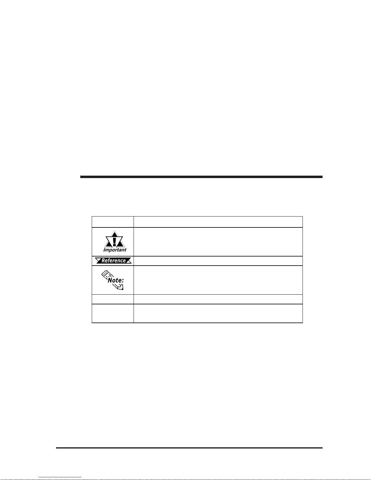
Symbol Meaning
Indicates import ant infor mation or pr ocedures that must be followed f or
correct and risk- f ree s of t ware/ device operation.
Refer s t o us eful or import ant s u pplemental inf o rmat ion.
Provides usef ul or import ant s u pplemental inf o rmat ion.
*1
Indicates us ef ul or importan t s upplemental inf or mation .
1) , 2)
Indicates s t eps in a pr ocedure. B e s ur e t o per f or m thes e steps in t he
order given.
The list below describes the documentation conventions used in this
manual.
Page 7
FP-2500/FP-2600 Series Models/ Features
6 FP-2500/FP-2600 Series User Manual
High Quality TFT Color LCD Display
The FP-2500 Series units are equipped with a 10.4 inch TFT type color LCD and the
FP-2600 Series units are equipped with a 12.1 inch TFT type color LCD. Both have
superb brightness and wide viewing angles, not found in ordinary laptop-type TFT
LCDs.
The FP-2500 Series units screen's maximum resolution is 640(H) X 480(W) pixels and
the FP-2600 Series units are 800(H) X 600(W) pixels. Bothe can display 260,000
colors.
Easy Installation In User Cabinets and Panels
The FP unit's slim and compact design makes installation a snap. These panels are
designed specifically for IA (Industrial Automation) or OA (Office Automation) monitor. The flat front panel provides protection equivalent to IP65f. Even without its
optional protective cover the front panel is highly resistant to both water and dust.
Panel can be used as a Display
Since the FP is equipped with an analog RGB interface and a DVI-D Interface, it can
be connected to a PC and other similar devices easily . (The PC's dot clock frequency ,
however, must be within the standard range.)
Easy-to-use Built-In Touch Panel
The FP unit's built-in touch panel is standard equipment, allowing touch panel data to be
output to a host PC via input/output commands and an RS-232C or USB cable. This is
ideal for systems requiring both touch panel operation and data monitoring.
FP-2500/FP-2600 Series Features
FP-2500/FP-2600 Series Models
The FP-2500/FP-2600 Series refers to the following FP model numbers:
Series
Model
Name
Model Type
Power Input
Type
Standards
FP2500-T12 AC
FP2500-T42-24V DC
UL/c-UL/CSA Approved,
CE Marked
FP2600-T12 AC
FP2600-T42-24V DC
UL/cUL Approved,
CE Marked
FP-2500 F P-2500T
FP-2600 F P-2600T
Page 8

Connecting the FP to a PC/What is IP65f?
FP-2500/FP-2600 Series User Manual 7
• When a signal timing value not compatible with the FP
unit is entered, or if the entered timing value is larger than
can be displayed by the dot clock, an "OUT OF RANGE"
message is displayed. If this occurs, consult your
computer's manual and enter a value that is compatible
with this device.
• If no signal (synchronized signal) is entered, a "NO SIGNAL" message is displayed.
The FP-2500 Series units are designed for standard VGA mode display and the FP2600 Series units are designed as a standard SVGA display .
Be aware that some types of VGA/SVGA equipment may not be within the ranges
specified in this document, and, therefore, cannot be connected to the FP .
Also, if you change your PC's VGA/SVGA board, there is the possiblity that the new
board may not be able to be connected to the FP.
2.3 Interface Specifications
Connecting the FP to a PC
This code indicates the degree of ingress protection provided from the front face of the
FP , and assumes that the FP is securely mounted into a metal panel.
This unit's protection rating of IP65f is actually a composite code, consisting of the
internationally recognized British "Ingress Protection" standard (BS EN 60529:1992) "IP65", and the standard developed by the Japanese Electronics Manufacturer's Association (JEM) - "f". This code is used in this manual to identify this product's degree of
structural resistance to a variety of environmental elements and thus, prevent problems
or accidents related to the inappropriate product use.
The individual meaning of each character of this code is explained below .
(1) Designates the type of protection provided.
(2) Indicates the degree of protection provided to the human body by the unit, and the
degree of protection provided by the unit's front face from particles/dust intrusion
into the interior of the unit.
Here, "6" indicates that the unit is completely protected from dust intrusion.
(3) Indicates the degree of protection provided by the unit's front face from water
intrusion into the interior of the unit.
Here, "5" indicates that the unit is protected from water intrusion from a direct water
jet.
(4) Indicates the degree of protection provided by the unit's front face from oil particle
intrusion into the interior of the unit.
Here, "f" indicates that the unit is completely protected from oil intrusion via either oil
particles or oil splashes from any direction (to the front panel).
IP 6 5 f
(1) (2) (3) (4)
What is IP65f?
Page 9
8 FP-2500/FP-2600 Series User Manual
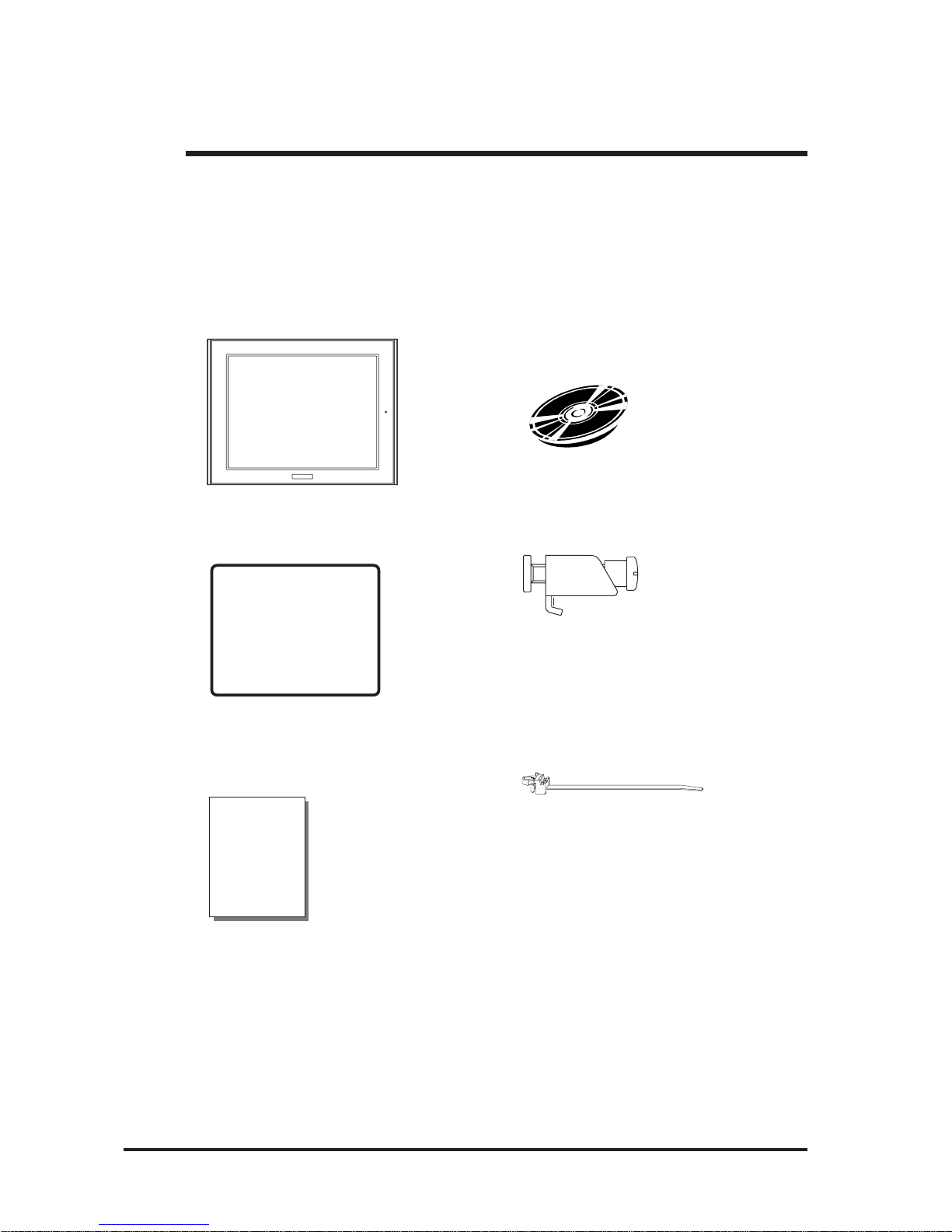
Package Contents
The FP unit's packing box contains the items listed below . Please check to be sure each
item is included and is not damaged.
FP unit (1) CD-ROM (1)
(FP2500-T12/FP2600-T12/ (F P-2500/FP-2600 Series User Manual &
FP2500-T42-24V/FP2600-T42-24V) Touch Panel Communication Programs
For MS-DOS®)
Installation Gasket (1) Installation Fasteners (4)
(Attached to the FP unit)
Installation Guide (1) USB Cable Strap (1)
(Japanese/English)
These items have all been carefully packed with special attention to product quality . However,
should you find anything damaged or missing, please contact your local FP distributor immediately for prompt service.
Package Contents
Installation
Guide
Page 10

UL/c-UL/CSA Application Notes/CE Marking Notes
FP-2500/FP-2600 Series User Manual 9
UL/c-UL/CSA Application Notes
The FP2500-T42-24V/FP2600-T42-24V units are UL/c-UL listed products (UL File No.
E182139).
The FP conforms as a component to the following standards:
UL508 Industrial Control Equipment
UL1604 Electrical Equipment for use in Class 1 & 2 - Division 2, and Class III
Hazardous (classified) locations.
CAN/CSA-C22.2, No.1010-1 Measuement and Control Equipment Safety require-
ments for electrical equipment for measurement and
laboratory use.
FP2500-T42-24V (UL Registration Model No.:3280033-02)
FP2600-T42-24V (UL Registration Model No.:3280033-04)
<Cautions>
Be aware of the following items when building the FP into an end-use product:
• The FP unit's rear face is not approved as an enclosure. When building the FP unit into an enduse product, be sure to use an enclosure that satisfies standards as the end-use product's overall
enclosure.
• The FP unit must be used indoors only .
• This unit should be installed in the front face of a metal panel.
• If the FP unit is installed so as to cool itself naturally , be sure to mount it in a vertical panel. Also,
be sure that the FP unit is installed at least 100 mm away from any adjacent structures or
machine parts. If these conditions are not met, the heat generated by the FP unit's internal
components may cause the unit to fail to meet UL standards.
UL1604 Conditions of Acceptability and Handling Cautions:
1. Power, input and output (I/O) wiring must be in accordance with Class I, Division 2 wiring
methods - Article 501- 4(b) of the National Electrical Code, NFP A 70 within the United
States, and in accordance with Section 18-152 of the Canadian Electrical Code for units
installed within Canada.
2. Suitable for use in Class I, Division 2, Groups A, B, C and D, Hazardous Locations.
3. W ARNING: Explosion hazard - substitution of components may impair suitability for Class I,
Division 2.
4. W ARNING: Explosion hazard - when in hazardous locations, turn power OFF before replac-
ing or wiring modules.
5. W ARNING: Explosion hazard - do not disconnect equipment unless power has been switched
OFF , or the area is known to be non-hazardous.
6. W ARNING: Explosion hazard - do not connect/disconnect equipment unless area is known to
be nonhazardous.
The FP2500-T42-24V/FP2600-T42-24V are CE marked products that conform to EMC directives EN55011 Class A and EN61000-6-2.
For detailed CE marking information, please contact your local FP distributor.
CE Marking Notes
Page 11
10 FP-2500/FP-2600 Series User Manual
CD-ROM Data
CD-ROM Data
The following data and programs are contained in the FP-2500/FP-2600 Series unit's
CD-ROM.
FP2000-MMCD-02
[Manual] User Manual
[Eng] fp2000e.pdf
[Jpn] fp2000j.pdf
[Reader] Acrobat® Reader
[Eng] ar505enu.exe
[Jpn] ar505jpn.exe
[Utility] Utility Setup <Supported OS>
[Touch] Touch Panel Communication Program *1 MS-DOS
®
FPATPH.CAL
FPATPH.EXE
FPCALIB.EXE
*1 These programs are only for MS-DOS® and FP-2500 series unit. When using
Windows®95, WindowsNT®4.0, Windows®98, Windows®2000 and Windows®XP,
the Mouse Emulator V2 (PL-TD000) is required.
1.2 Optional Equipment
The revision version can be determined by the identification label or revision stickers
that are placed on the main unit of the FP . The characters and numerals in the "REV"
area that are replaced with asterisks (*), or marked with a marker indicate the revision
version.
In the example below , the asterisks "*" are placed at positions "D", "1", and "2", which
indicates the revision version as "D, 1, 2".
Identification Label
Revision V ersion
Page 12

Table of Contents
FP-2500/FP-2600 Series User Manual 11
Table of Contents
Preface..................................................................................................................... 1
Essential Safety Precautions.................................................................................2
Documentation Conventions.................................................................................5
FP-2500/FP-2600 Series Models ............................................................................6
FP-2500/FP-2600 Series Features .........................................................................6
Connecting the FP to a PC..................................................................................... 7
What is IP65f? .........................................................................................................7
Package Contents ..................................................................................................8
UL/c-UL/CSA Application Notes ............................................................................9
CE Marking Notes ...................................................................................................9
Revision Version...................................................................................................10
CD-ROM Data ........................................................................................................10
Chapter 1 Introduction
1. 1 System Design ............................................................................ 1-1
1.2 Optional Equipment................................................................... 1-2
Chapter 2 Specifications
2. 1 General Specifications .............................................................. 2-1
2.1.1 Electrical ........................................................................................2-1
2.1.2 Environmental.................................................................................2-2
2.1.3 Structural .......................................................................................2-2
2. 2 Functional Specifications .......................................................... 2-3
2.2.1 Performance...................................................................................2-3
2.2.2 Display...........................................................................................2-3
2. 3 Interface Specifications............................................................. 2-4
2.3.1 Analog RGB Interface ....................................................................2-4
2.3.2 DVI-D Interface.............................................................................2-7
2.3.3 RS-232C Interface.........................................................................2-9
2.3.4 USB Interface ..............................................................................2-10
Page 13

Table of Contents
12 FP-2500/FP-2600 Series User Manual
2. 4 Cable Diagrams ....................................................................... 2-11
2.4.1 Analog RGB Interface Pin Connections (Optional cable)................ 2-11
2.4.2 DVI-D Interface Pin Connections (Optional cable) ........................2-12
2.4.3 RS-232C Interface Pin Connections (Optional cable) ....................2-13
2.4.4 USB Interface Cable Pin Connections (Option cable) ....................2-13
2. 5 Names and Functions of FP Parts ......................................... 2-14
2. 6 FP Dimensions .......................................................................... 2-15
2.6.1 External Dimensions ....................................................................2-15
2.6.2 External Dimensions (with Installation Fasteners) ...........................2-16
2.6.3 Installation Fasteners ....................................................................2-17
2.6.4 FP Panel Cut Dimensions .............................................................2-17
Chapter 3 Installation and Wiring
3.1 Installation...................................................................... 3-1
3.1.1 Installation Procedures....................................................................3-1
3.2 Wiring Cautions ......................................................................... 3-6
3.2.1 Connecting the Power Cord ...........................................................3-6
3.2.2 Connecting the USB Cable Strap Attachment .................................3-8
3.2.3 Connecting the Power Supply ........................................................3-9
3.2.4 Precautions: Grounding ................................................................3-10
3.2.5 Precautions: Input/Output Signal Lines .........................................3-10
Chapter 4 Setting up and Adjusting the FP unit
4. 1 Operation Mode Setup .............................................................. 4-1
4.1.1 Dip Switch Preset Settings and Adjustments ...................................4-1
4.1.2 Status of Front LED in Operation Modes........................................4-2
4.2 Screen Display Adjustment....................................................... 4-2
4.2.1 Calibration of OSD Display Position ...............................................4-2
4.2.2 OSD Setting Icons .........................................................................4-3
4.2.3 OSD Setting Item Details................................................................4-4
Page 14

Table of Contents
FP-2500/FP-2600 Series User Manual 13
Chapter 5 Touch Panel Data
5. 1 Touch Interface Data................................................................. 5-1
5. 2 Touch Panel Communication Programs For MS-DOS® .... 5-4
5.2.1 FPATPH.EXE (T ouch Panel Handler) ............................................5-4
5.2.2 FPCALIB.EXE (T ouch Panel Data FPCalibration) ........................5-8
Chapter 6 Troubleshooting
6.1 Troubleshooting ......................................................................... 6-1
6.1.1 Possible Device Problems...............................................................6-1
6.1.2 No Display ....................................................................................6-2
6.1.3 T ouch Panel Does Not Respond ...................................................6-4
6.2 Error Message ........................................................................... 6-5
6.2.1 Error Message List .......................................................................6-5
Chapter 7 Maintenance
7.1 Regular Cleaning ...................................................................... 7-1
7.1.1 Cleaning the Display .......................................................................7-1
7.1.2 Installation Gasket Replacement......................................................7-2
7.2 Periodic Check Points ............................................................. 7-3
7.3 Backlight Replacement............................................................ 7-4
7.3.1 Replacing GP577R T-BL00-MS .....................................................7-6
7.3.2 Replacing PS600-BU00 .................................................................7-8
7.3.3 Replacing CA3-BLU12-01 ..........................................................7-10
Page 15

14 FP-2500/FP-2600 Series User Manual14
Memo
Page 16
1.1 System Design
1-1FP-2500/FP-2600 Series User Manual
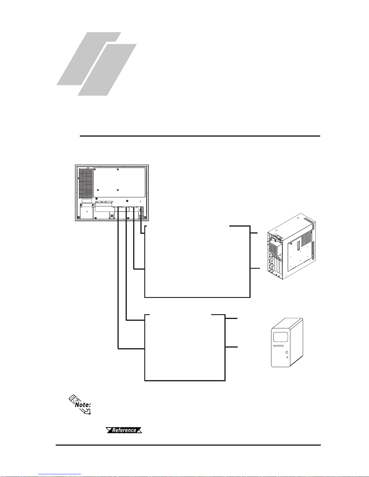
The FP unit’s dip switches set the type of communication method used for sending
touch data and commands (USB or RS-232C), and also for outputing image signals
(DVI-D or Analog RGB).
4.1.1 Dip switch setting
USB Interface Cable
FP-US00 <5m>
A-B type Cable
For Touch data and Command transmission
RS-232C Interface Cable
FP61V-IS00-O <5 m>
Straight Cable : Dsub 9-pin female
For Touch data and Command transmission
DVI-D Cable
FP-DV01-50 <5 m>
For image signal output
Analog RGB Interface Cable
FP-CV00 <2.5m>, FP-CV01 <5m>
FP-CV02-45<4.5m>
For image signal output
Chapter 1
Introduction
1. System Design
2. Optional Equipment
1.1 System Design
PS-2000B
or
Windows
®
compatible PC
FP unit
The FP can be connected to Pro-face's PS-2000B or to a Windows® compatible PC.
Image Signal Output
Touch Panel Communication
Page 17
1.2 Optional Equipment
1-2 FP-2500/FP-2600 Series User Manual
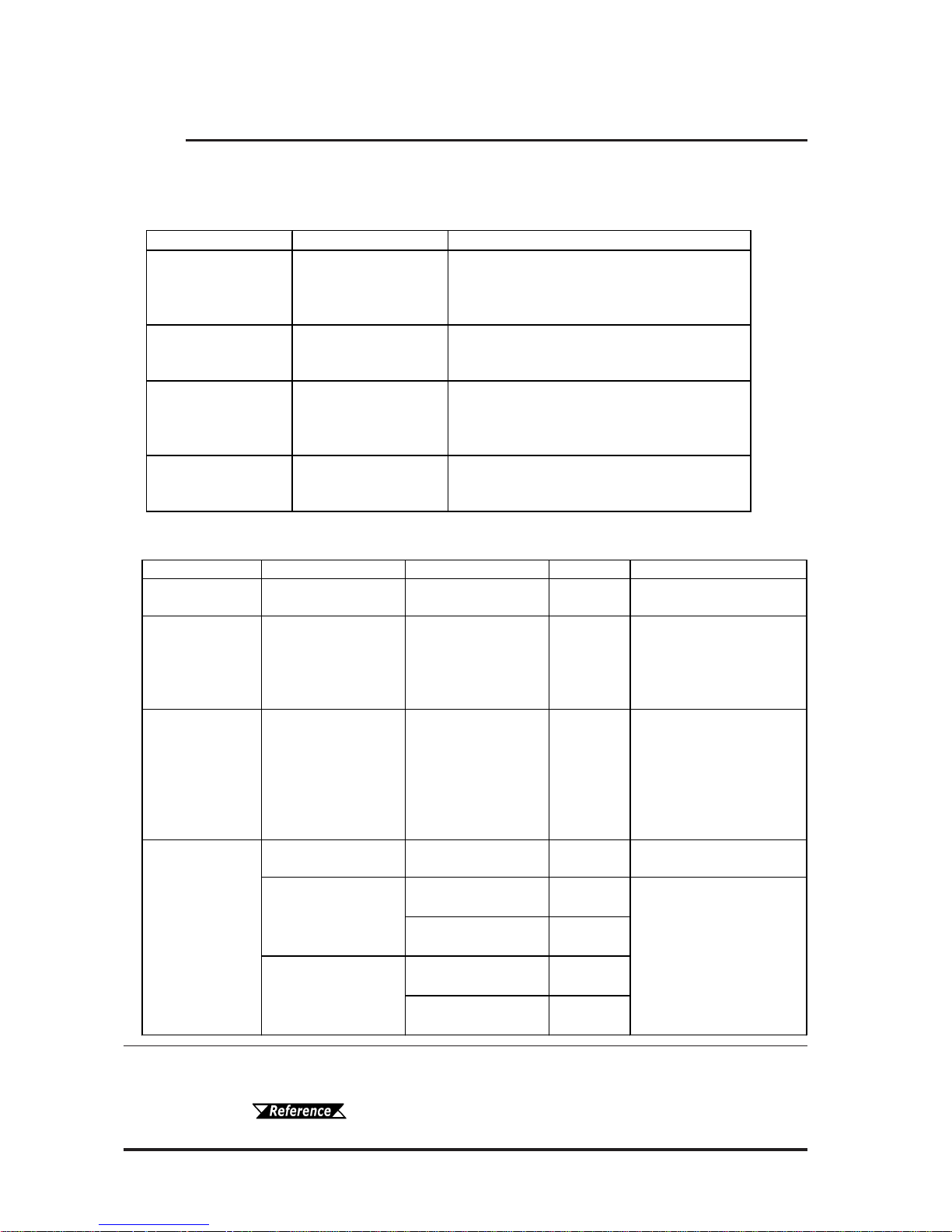
1.2 Optional Equipment
All optional items listed below are Digital Electronics Corporation products.
Item Model Number Description
RS-232 C Cabl e FP 61V-IS00-O (5 m )
Seri al in t erfac e cable used for touc h panel data
transmissi on between the host and t he F P or
command transmission to the FP. This is a
straight Dsub 9-pin femal e cable.
Analog RGB Cable
FP -CV00 (2.5m)
FP -CV01 (5m)
FP -CV02-45 (4. 5m )
Analog RGB i nt erface c abl e used when image
signals are output to the FP from the host.
(Dsub 15-p i n m al e ).
USB Cable FP-US00 (5m)
USB i nterface c abl e used for touc h panel data
trans fer between the hos t and the FP or
command transmission to the FP. A-B type
cable.
DVI-D Cable F P-DV01-50 (5 m )
Digital V i sual Interface cabl e us ed to send the
image signal from the host to the FP. XGA
spec i fic ation DVI-D 24-pin male.
Cables
Maintenance Parts
Item Model Number Corresponding FP Rev. Description
Installation
Fasteners
GP070-AT01
FP-250 0 S eri es
FP-260 0 S eri es
-
Metal installation
fasteners.
Rubber Gasket GP570-WP10-MS
FP-250 0 S eri es
FP-260 0 S eri es
-
Replac em ent rubber
gask et, us ed when
installing the FP. Same as
the FP uni t 's origi nal
gasket.
Sc reen P rot ec tion
Sheet
PSL-DF00
FP-250 0 S eri es
FP-260 0 S eri es
-
Dis posable, di rt resis t an t
sheet for the FP unit's
screen. The FP unit's
touch panel c an be used
with this cover
sheet attached.
(5 sheets/set)
GP577RT-BL00-MS F P -2500 S eries -
Replac em ent backlight for
FP-250 0 S eri es unit s.
FP2600-T12
Rev.1 is not
marked.
*1
FP2600-T42-24V
Rev.1 is not
marked.
*1
FP2600-T12
Rev.1 is
marked.
*1
FP2600-T42-24V
Rev.1 is
marked.
*1
Replac em ent backlight for
FP-260 0 S eri es unit s.
Backlight
PS600-BU00
CA3-BLU12-01
*1 The corresponding backlight unit differs depending on FP-2600 Series unit's
marked Revision.
For more information on how to determine the revision version,
see "Revision Version" (Page 10).
Page 18

1.2 Optional Equipment
1-3FP-2500/FP-2600 Series User Manual
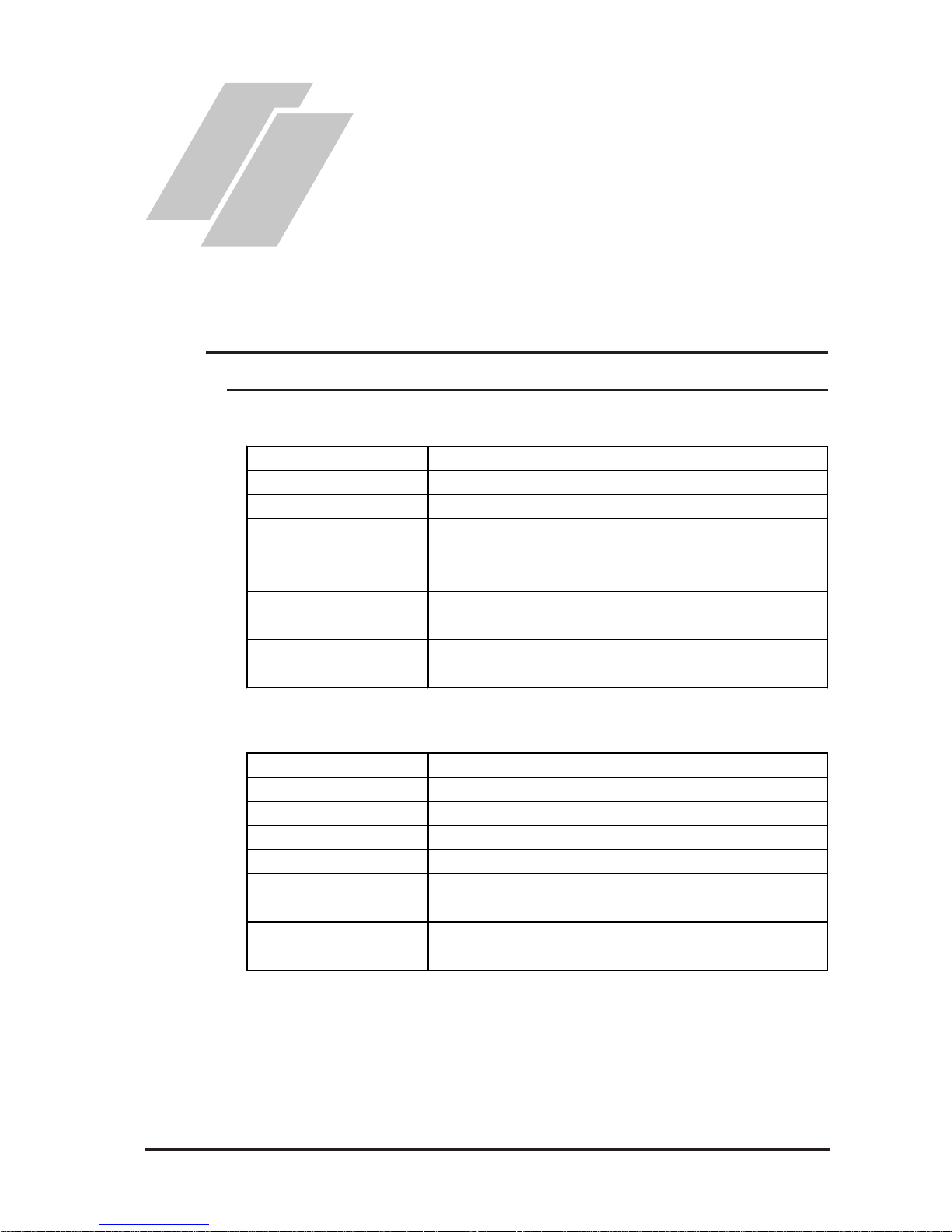
Item Model Number Description
Mous e E m ul at or V 2
*1
PL-TD000 Mouse emulation s o ft ware for t he F P.
Available Software
*1 OS can be Windows®95, WindowsNT®4.0, Windows®98, Windows®2000 or
Windows
®
XP .
Page 19

1.2 Optional Equipment
1-4 FP-2500/FP-2600 Series User Manual
Memo
Page 20
FP-2500/FP-2600 Series User Manual
2-1
2.1.1 Electrical
1. General Specifications
2. Functional Specifications
3. Interface Specifications
4. Cable Diagrams
5. Names and Functions of FP
Parts
6. FP Dimensions
Chapter 2
Specifications
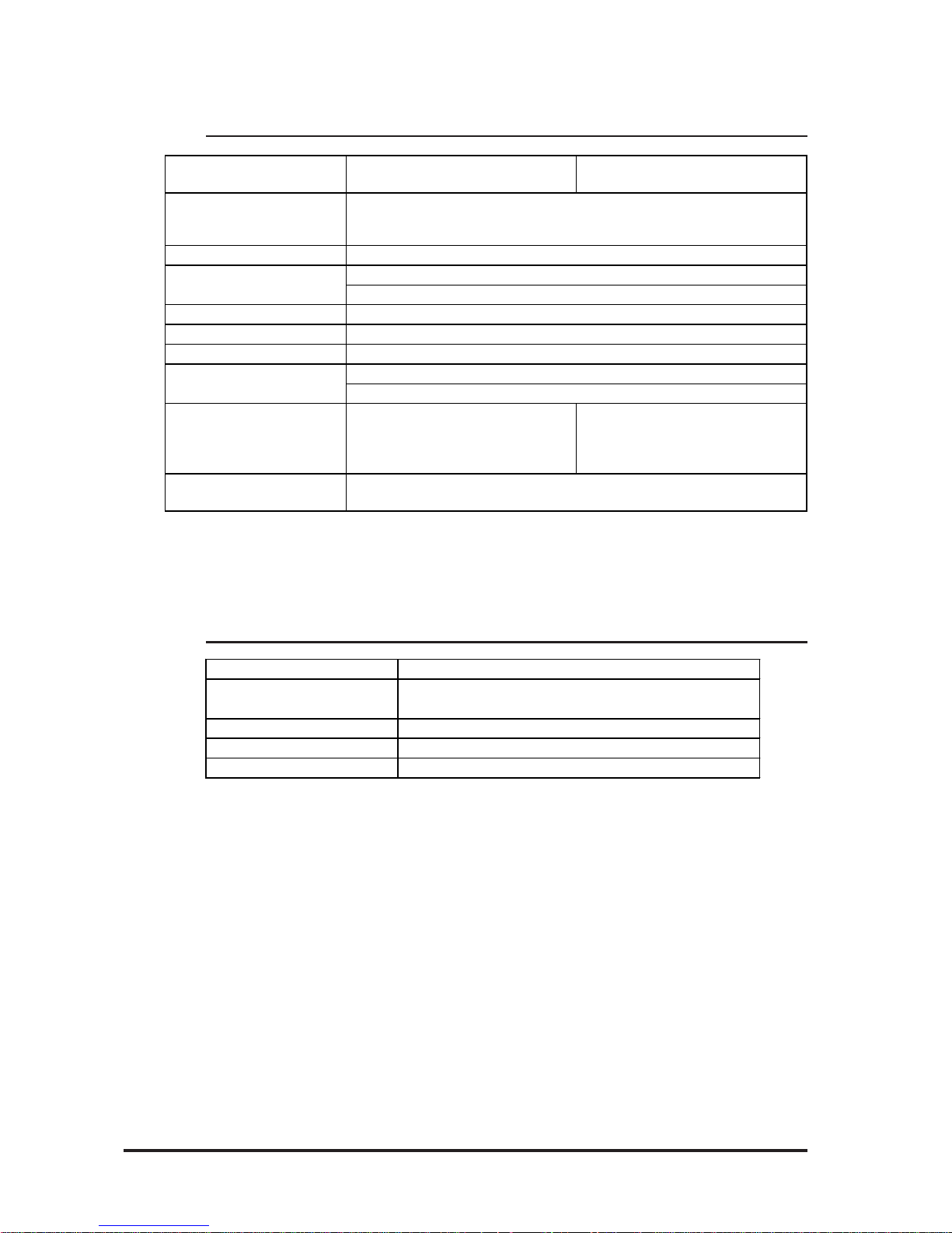
2.1 General Specifications
Ra ted V o lta g e
A C 100V to AC 240V
Rated Vol ta ge Range
A C 85V to AC 264V
Rated Fre quency
50/60 Hz
Rated Fre quency Range
47 Hz to 63 Hz
Allowable Voltage Drop
20ms or less
Pow er Consumption
50VA (ACIN 100V)/ 85VA ( ACIN 240V)
Voltage Endurance
A C 1500V 20mA for 1 minute
(between charging and FG terminals)
In sula tion Resistanc e
10MΩ or higher at DC500V
(between charging and FG terminals)
FP2500-T12/FP2600-T12
FP2500-T42-24V/FP2600-T42-24V
Ra ted V o lta g e
DC24V
Rated Vol ta ge Range
DC19.2 to DC28.8V
Allowable Voltage Drop
10ms or less
In-rush Current
30A or less
Pow er Consumption
50W or les s
Voltage Endurance
A C 1000V 20mA for 1 minute
(between charging and FG terminals)
In sula tion Resistanc e
10MΩ or higher at DC500V
(between charging and FG terminals)
Page 21
FP-2500/FP-2600 Series User Manual
2.1 General Specifications
2-2
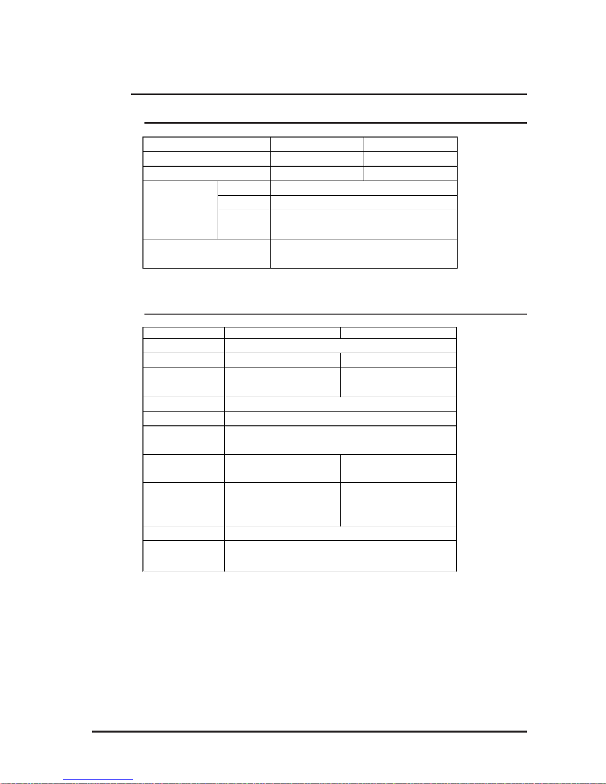
2.1.3 Structural
* 1 The front face of the FP unit, installed in a solid panel, has been tested using condi-
tions equivalent to the standard shown in the specification . Even though the FP unit’s
level of resistance is equivalent to the standard, oils that should have no effect on the
FP can possibly harm the unit. This can occur in areas where either vaporized oils are
present, or where low viscosity cutting oils are allowed to adhere to the unit for long
periods of time. If the FP’s front face protection sheet peels off, these conditions can
lead to the ingress of oil into the FP and separate protection measures are suggested.
Also, if non-approved oils are present, it may cause deformation or corrosion of the
front panel’s plastic cover. Therefore, prior to installing the FP be sure to confirm the
type of conditions that will be present in the FP’s operating environment.
If the installation gasket is used for a long period of time, or if the unit and its gasket
are removed from the panel, the original level of the protection cannot be guaranteed.
To maintain the original protection level, be sure to replace the installation gasket
regularly.
Grounding
External Dim ensions
Weight
Cooling Me thod
Ratings
*1
(
For front panel of installed unit
)
Natural air circulation
100Ω or less , or your country's applicable st an dar d
W317mm [12.48 in] x H243mm [9.57 in] x D58mm [ 2. 28 in]
3.5kg
(
7.7lb) or less
Equivalent to I P 65f ( J E M 1030)
2.1.2 Environmental
FP2500-T12
FP2600-T12
FP2500-T42-24V
FP2600-T42-24V
Ambient Operating
Temperature
Storage Temperature
Air P u r ity (Dust)
Pollution De gre e
Corro sive Gasses
Noise Immunity
(via noise em ul ator)
Noise Voltage: 1,500Vp-p
Pulse Durat ion: 1ms, 500ns, 50ns
Rise Time: 1ns
Noise Voltage: 1,000Vp-p
Pulse Durat ion: 1ms, 500ns, 50ns
Rise Time: 1ns
Electrostatic Discharge
Immunity
10Hz to 25Hz 19.6m/s
2
X, Y, Z directions (30min.)
4kV (complies wit h E N 6100 0- 4- 2)
Vibra tion Re sista nce
0oC to +50oC
*1
(the panel f ace should not incline more than 30oC)
-10
o
C to +60oC
30%RH to 90%RH
(Non condensing, wet bulb temperature: 39
o
C or less)
Free of dus t
Pollution Degree 2
Free of corrosiv e gasses
Ambie nt Humidity
* 1 When using a FP-2600 Series unit in an environment where the temperature reaches or
exceeds 40
o
C for an extended period of time, the screen contrast level may decrease
from its original level.
Page 22
FP-2500/FP-2600 Series User Manual
2.2 Functional Specifications
2-3
*1 Setting up OSD. For details, refer to 4.2 Screen Display Ajustment
*2 For details, refer to 2.3 Interface Specifications
*3 50% decreased brightness indicates the backlight needs to be replaced. This value
is only for reference and not a guaranteed value.
2.2.1 Performance
2.2.2 Display
FP-2500 Series FP-2600 Series
V GA (640 X 480) SVGA (800 X 600)
10.4 inch TFT VGA 12.1 inch TFT SVGA
Type
Resolution
Interface
A nalog RGB Interface
DV I-D I nt erface
Resist ive Film (Analog)
1024 X 1024
Serial Interface (RS- 232C)
USB Interface
Vide o I / F
Touch Pane l I / F
Graphics
Displ ay Uni t
FP-2500 Series FP -2600 S eri es
Type
Resolution
640 (H) X 480 ( V) pixels 800 (H) X 600 ( V) pixels
Dot P i t ch
0.330mm [ 0.01in.] (H) X
0.330mm [0.01in. ] ( V)
0.3075mm [0.01in.] (H) X
0.3075mm [0.01in.] (V)
Displa y co l o r s
Brightness Control
Contrast Control
Display area
*1
211.2mm [8.31in. ] ( W) X
158.4mm [6.24 in.] (H)
246.0mm [9.69in. ] ( W) X
184.5mm [7.26in. ] ( H)
Display Modes
*2
640X350, 640X 400,
640X480, 720X 350,
720X400
640X350, 640X 400,
640X480, 720X 350,
720X400, 800X 600
Backlight
Backlight Lifetime
CCFL (Replaceable)
Backlight can be replaced by t he user .
50,000 hours at an ambient temperature of 25
oC*3
TFT Activ e Matrix Color LCD
260,000 colors (R/G/ B six bits each)
Available
A vailable (Analog RGB only)
(when using analog RGB connect ion)
2.2 Functional Specifications
Page 23
FP-2500/FP-2600 Series User Manual
2.3 Interface Specifications
2-4
2.3.1 Analog RGB Interface
2.3 Interface Specifications
Input s ignal t ype A n alog RGB
Input signal charact eris t ic Image signal: analog RGB
Synchronous signal: TTL level, negative tr ue or po sitive tr ue
Scanning type: non-int erlaced
Setting v ia OSD
(On Screen Display)
CONTRAST
BRIGHTNESS
H-POS
V-POS
H-SIZE
PHASE
BA CKLIGHT
DEFAULT (ALL CLEA R)
The number of dots (pixels) displayed are as follows:
Resolution
H Sync.
(kHz)
V Sync
(Hz)
Dot Clock
(MHz)
Screen
Resolution
Expansion
(H : Horizontal)
(V : Vert ical)
Display
Resolution
640×350
*1
31.469 70.000 25.175 640×420
640×400 31.469 70.000 25.175 640×480
640×400 24.827 56.420 21.053 640×480
640×480 31.469 59.992 25.175 ×1.0 640×480
720×350 *
1,2,3
31.469 70.000 28.320 640×420
720×400
*2,3
31.469 70.000 28.320 640×480
×1.0(H)
×1.2(V)
×1.0(H)
×1.2(V)
FP-2500 Series
* 1 When the 350 pixel (vertical) signal setting is selected, 400 pixels, including 50 pixels
at the top and at the bottom of the screen, will be enlarged and displayed at 480 pixels
(1.2times).
* 2Select "720 x 400 Display Resolution 720 x 400 DSP" in the OSD (On Screen Display)
"System Setting" screen.
* 3 When the 720 pixel (horizontal) signal setting is selected,
- When "720 x 400 DSP" is ON; only 640 pixels are displayed (80 pixels are not
displayed.)
- When "720 x 400 DSP" is OFF; all pixels are displayed but images may be partially
cut off.
Page 24

FP-2500/FP-2600 Series User Manual
2.3 Interface Specifications
2-5
FP-2600 Series
Resolution
H Sync.
(kHz)
V Sync
(Hz)
Dot Clock
(MHz)
Screen
Resolution
Expansion
(H : Horizontal)
(V : Vert ical)
Display
Resolution
640×350
*1
31.469 70.000 25.175 800×525
640×400 31.469 70.000 25.175 800×600
640×400 24.827 56.420 21.053 800×600
640×480 31.469 59.992 25.175 800×600
640×480 35.000 66.670 30.240 800×600
640×480 37.861 72.810 31.500 800×600
720×350
*1*2
31.469 70.000 28.320 ×1.0(H) 720×525
720×400
*2
31.469 70.000 28.320 ×1.5(V) 720×600
800×600 35.156 56.250 36.000 800×600
800×600 37.879 60.317 40.000 800×600
×1.25(H)
×1.5(V)
×1.0
×1.25(H)
×1.25(V)
*1 When the 350 pixel (vertical) signal setting is selected, 400 pixels, including 50 pixels at
the top and at the bottom of the screen will be enlarged and displayed at 600 pixels
(1.5times).
*2Select "720 x 400 Display Resolution 720 x 400 DSP" in the OSD (On Scr een Display)
"System Setting" screen.
Page 25

FP-2500/FP-2600 Series User Manual
2.3 Interface Specifications
2-6
Analog RGB Interface
Pin Assignments and Signal Names
11
15
1
5
Pin No. Signa l Na m e Condition Pin Loca tion
1 A nalog R R signal input
2 A nalog G G s ignal input
3 A nalog B B signal input
4 Reserv ed NC (spare for input )
5 Digital ground ing Digital s ignal GND
6 Return R R signal GND
7 Return G G signal GND
8 Return B B signal GND
9 Reserv ed NC (spare for input )
10 Digital grounding Digital s ignal GND
11 Reserved NC (spare for input)
12 Reserved NC (spare for input)
13 H. SY NC
Horizontal synchronous
signal input
14 V. SYNC
Vertical synchronous signal
input
15 Reserved NC (spare for input)
Connector: Mini Dsub 15 pin male
Connector set screw: Inch type (4-40)
Analog RGB Cable:
FP-CV00<2.5m>, FP-CV01<5m>, FP-CV02-45 <4.5m>
manufactured by
Digital Electronics Corporation of Japan
If a cable other than the specified RGB cable is used, FP unit operation
cannot be guaranteed due to the possibility of noise interference.
Page 26

FP-2500/FP-2600 Series User Manual
2.3 Interface Specifications
2-7
2.3.2 DVI-D Interface
The number of dots (pixels) displayed are as follows:
Input signal type DVI-D
Sett ing by OSD
(On Screen Display)
H-POS
V-POS
BA CKLIGHT
DEFAULT (ALL CLEA R)
Resolution
H Sync.
(kHz)
V Sync
(Hz)
Dot Clock
(MHz)
Screen
Resolution
Expansion
(H : Horizontal)
(V : Vert ical)
Display
Resolution
640×400 31.469 70.000 25.175 640×480
640×400 24.827 56.420 21.053 640×480
640×480 31.469 59.992 25.175 ×1.0 640×480
640×480
×1.0(H)
×1.2(V)
×1.0(H)
×1.2(V)
720×400
*1
31.469 70.000 28.320
FP-2500 Series
* 1 When the horizontal 720 pixel signal is input;
-VGA Graphic & Text mode displays 640 pixels only and 80 pixels are not displayed.
Resolution
H Sync.
(kHz)
V Sync
(Hz)
Dot Clock
(MHz)
Screen
Resolution
Expansion
(H : Horizontal)
(V : Vert ical)
Display
Resolution
640×400 31.469 70.000 25.175 800×600
640×400 24.827 56.420 21.053 800×600
640×480 31.469 59.992 25.175 800×600
640×480 35.000 66.670 30.240 800×600
640×480 37.861 72.810 31.500 800×600
720×400
*1
31.469 70.000 28.320
×1.0(H)
×1.5(V)
720×600
800×600 35.156 56.250 36.000 800×600
800×600 37.879 60.317 40.000 800×600
×1.25(H)
×1.5(V)
×1.25(H)
×1.25(V)
×1.0
FP-2600 Series
* 1When you use this resolution, select "720 x 400 Display Resolution 720 x 400 DSP" in
"System Setting" of the OSD (On Screen Display) .
Page 27

FP-2500/FP-2600 Series User Manual
2.3 Interface Specifications
2-8
Pin
No.
Signal Na me
Pin
No.
Signal Name Pin Location
1 TMDS DATA2- 13 NC
2 TMDS DATA2+ 14 NC
3 TMDS DA TA2/4 SHI E LD 15 GND (+5V)
4 NC 16 Hot Plug Detect
5NC17TMDS DATA06 DDC Clock 18 TMDS DA TA0+
7 DDC Data 19 TMDS DATA0/5 SHIE LD
8NC20NC
9 TMDS DATA1- 21 NC
10 TMDS DATA 1+ 22 TMDS C LOCK S HIELD
11 TMDS DATA1/3 S HI ELD 23 TMDS CLOCK+
12 NC 24 TMDS CLOCK-
DVI-D Interface
Pin Assignments and Signal Names
Connector: DVI-D 24-pin male
Connector set screw: Inch type (4-40)
DVI-D Cable: FP-DV01-50 <5 m> manufactured by Digital Electronics
Corporation
24
17
8
1
• If a cable other than the specified DVI-D cable is used, FP unit operation cannot be guaranteed due to the possibility of noise interference.
Page 28

FP-2500/FP-2600 Series User Manual
2.3 Interface Specifications
2-9
Signal Names
Signal names used for the RS-232C Interface are designed to match the pin order
used on most PC RS-232C interfaces, which allows a straight cable to be used to
connect the two.
Therefore, connect each pin's signal to the same signal name on
the PC side.
For example, the FP unit connector's pin #2 'RD' should be connected to the PC
connector's 'RD' terminal. For detailed signal direction information,
2.4 Cable Diagrams
2.3.3 RS-232C Interface
RS-232C Interface
Pin Assignments and Signal Names
Connector: Dsub 9 pin female
Connector set screw: Inch type (4-40)
RS-232C Cable: FP61V-IS00-O <5m> manufactured by Digital Electronics
Corporation of Japan
*1 CD, DTR, and DSR are connected together inside the FP.
If a cable other than the specified RS-232C cable is used, FP unit operation cannot be guaranteed due to the possibility of noise interference.
6
9
1
5
Pin No. S i gna l Na m e Condition Pi n Loca tion
1 CD Carrier Detect
*1
2 RD Receive D ata (FP-> Hos t)
3 SD Send Data (FP<-Host)
4 D TR Data Ter minal Ready
*1
5 GND Ground
6 DSR Data Set Ready
*1
7 RS Request t o S end (FP < - Hos t )
8 CS Clear to Send (FP->Host)
9 NC (Used internally)
RS-232C Int erface
Baud rate: 96 00 bps
Data length: 8 bit s
Parity: none
Stop bit: 1
Page 29

FP-2500/FP-2600 Series User Manual
2.3 Interface Specifications
2-10
Pin
NO.
Signal
Name
Condition Pin Loca tion
1 USB1-5V +5V I N
2 USBD1(-) USB data(-)
3 USBD1(+) USB data(+)
4 GND Grou nd
2.3.4 USB Interface
USB Interface
Pin Assignments and Signal Names
Communication : Low speed Device
Connector : B type connector
USB Cable : FP-US00 <5m> manufactured by Digital Electronics Corporation
1
2
43
If a cable other than the specified USB cable is used, FP unit operation
cannot be guaranteed due to the possibility of noise interference.
Page 30

FP-2500/FP-2600 Series User Manual
2.4 Cable Diagrams
2-11
2.4 Cable Diagrams
Signals and signal names used with the FP and the Analog RGB cable (optional cable) are
the same as those used for PCs. Also, the same pin is used on both sides of the optional
cable so that you can connect the cable regardless of the cable direction.
Inch is used for the pitch of the connector screw on the PC. For this reason, inch (4-40) is
also used for the pitch of the connector screw for the cable and the FP .
FP
PC
RGB cable
1 Analog R Input
2 Analog G Input
3 Analog B Input
4 Reserved -5 Digital ground -6 Return R -7 Return G -8 Return B --
9 Reserved -10 Digital ground -11 Reserved --
12 Reserved --
13 H.SYNC Input
14 V.SYNC Input
15 Reserved --
FG FG --
1RED IN
2GRN IN
3BLU IN
4NC
5GND
6RED GND
7GRN GND
8BLU GND
9NC
10 GND
11 NC
12 NC
13 HSYN
14 VSYN
15 NC
FG FG
RED VIDEO 1
GRN VIDEO 2
BLU VIDEO 3
NC 4
GROUN D 5
GROUND RED 6
GROUND GRN 7
GROUND BLU 8
NC 9
GROUN D 10
MONITOR 11
SENSE(COLOR)
MONITOR 12
SENSE(MONO)
HSYN 13
VSYN 14
NC 15
FG FG
Output RED VIDEO 1
Output GRN VIDEO 2
Output BLU VIDEO 3
-- NC 4
-- GROUN D 5
-- GROUN D RED 6
-- GROUND GRN 7
-- GROUN D BLU 8
-- NC 9
-- GROUN D 10
-- MONITOR 11
--
SENSE(COLOR)
-- MONITOR 12
SENSE(MONO)
Output HSYN 13
Output VSYN 14
-- NC 15
2.4.1 Analog RGB Interface Pin Connections (Optional cable)
Page 31

FP-2500/FP-2600 Series User Manual
2.4 Cable Diagrams
2-12
2.4.2 DVI-D Interface Pin Connections (Optional cable)
Signals and signal names used with the FP and the DVI-D cable (optional cable) are the
same as those used for the PC. Also, the same pin is used on both sides of the optional
cable so that you can use the cable without worrying about the cable's direction.
Inch is used for the pitch of the connector screw on the PC. For this reason, inch (4-40) is
also used for the pitch of the connector screw for the cable and the FP .
FP PC
DVI-D cable
1 TMDS DATA2- Input
2 TMDS DATA2+ Input
3 TMDS DATA2/4 SHIELD -4NC -5NC -6DDC Clock -7 DDC Da ta -8NC --
9 TMDS DATA1- Input
10 TMDS DATA1+ Input
11 TMDS DATA1/3 SHIELD -12 NC -13 NC -14 NC -15 GND(+5V) -16 Hot Plug Detect -17 TMDS DATA0- Input
18 TMDS DATA0+ Input
19 TMDS DATA0/5 SHIELD -20 NC -21 NC -22 TMDS CLOCK SHIELD -23 TMDS CLOCK+ Input
24 TMDS CLOCK- Input
FG FG --
1TMDS DATA22TMDS DATA2+
3 TMDS DATA2/4 SHIELD
4NC
5NC
6 DDC Clock
7 DDC Data
8NC
9TMDS DATA110 TMDS DATA1+
11 TMDS DATA1/3 SHIELD
12 NC
13 NC
14 +5V Power
15 GND(+5V)
16 Hot Plug Detect
17 TMDS DATA018 TMDS DATA0+
19 TMDS DATA0/5 SHIELD
20 NC
21 NC
22 TMDS CLOCK SHIELD
23 TMDS CLOCK+
24 TMDS CLOCK-
FG FG
TMDS DATA2- 1
TMDS DATA2+ 2
TMDS DATA2/4 SHIELD 3
NC 4
NC 5
DDC Clock 6
DDC Data 7
NC 8
TMDS DATA1- 9
TMDS DATA1+ 10
TMDS DATA1/3 SHIELD 11
NC 12
NC 13
+5V Power 14
GND(+5V) 15
Hot Plug Detect 16
TMDS DATA0- 17
TMDS DATA0+ 18
TMDS DATA0/5 SHIELD 19
NC 20
NC 21
TMDS CLOCK SHIELD 22
TMDS CLOCK+ 23
TMDS CLOCK- 24
FG FG
Input TMDS DATA2- 1
Input TMDS DATA2+ 2
-- TMDS DATA2/4 SHIELD 3
-- NC 4
-- NC 5
-- DDC Clock 6
-- DDC Data 7
-- NC 8
Input TMDS DATA1- 9
Input TMDS DATA1+ 10
-- TMDS DATA1/3 SHIELD 11
-- NC 12
-- NC 13
-- +5V Power 14
-- GND(+5V) 15
-- Hot Plug Detect 16
Input TMDS DATA0- 17
Input TMDS DATA0+ 18
-- TMDS DATA0/5 SHIELD 19
-- NC 20
-- NC 21
-- TMDS CLOCK SHIELD 22
Input TMDS CLOCK+ 23
Input TMDS CLOCK- 24
Page 32

FP-2500/FP-2600 Series User Manual
2.4 Cable Diagrams
2-13
2.4.3 RS-232C Interface Pin Connections (Optional cable)
Signals and signal names used with the FP and the RS-232C cable (optional cable) are the
same as those used for PCs. Also, the same pin is used on both sides of the optional cable
so that you can connect the cable regardless of the cable direction.
Inch is used for the pitch of the connector screw on the PC. For this reason, inch (4-40) is
also used for the pitch of the connector screw for the cable and the FP .
1 CD Output 1 CD CD 1 Input CD 1
2 RD Output 2 RD RD 2 Input RD 2
3 SD Input 3 SD SD 3 Output SD 3
4 DTR Input 4 DTR DTR 4 Output DTR 4
5 GND 5 GND GND 5 GND 5
6 DSR Output 6 D SR DSR 6 Input DSR 6
7 RS Input 7 RS RS 7 Output RS 7
8 CS Output 8 CS CS 8 Input CS 8
9 NC 9 NC RI 9 Input RI 9
FG FG FG FG FG FG
FP SIO cable PC
2.4.4 USB Interface Cable Pin Connections (Option cable)
1
+5VIN
Input
2
USB-
Input/Output
3
USB+
Input/Output
4
GND
Input/Output
1
+5VIN
Input
2
USB-
Input/Output
3
USB+
Input/Output
4
GND
Input/Output
Output
+5VIN
1
Input/Output
USB-
2
Input/Output
USB+
3
Input/Output
GND
4
Output
+5VIN
1
Input/Output
USB-
2
Input/Output
USB+
3
Input/Output
GND
4
FP
USB cable
PC
Page 33

FP-2500/FP-2600 Series User Manual
2.5 Names and Functions of FP Parts
2-14
A : TFT Color LCD
Displays host data.
B : Touch Panel
Switches screens or writes/sends data to the host.
C : Front LED
Used to indicate status of power supply , backlight
or image signal input.
3.3.2 Status of Front LED in Op-
eration Modes
D : Power Input Terminal Block
Provides power to the FP unit via the input and
ground terminals
E : Dip Switches
Switches for setting up the FP unit's Operation
Mode.
G : Analog RGB Connector
Connector for analog RGB cable.
H : DVI-D Interface Connector
Connector for DVI-D calbe.
I : RS-232C Connector
Connector for RS-232C (serial) interface. Used
sending touch panel data to the host, and receiving
commands from the host.
J : USB Connector
Connector for USB cable. Used for sending touch
panel data to the host, and receiving commands
from the host.
2.5 Names and Functions of FP Parts
A B
C
FP-2500 Series Front
FP-2600 Series Front
Rear
Bottom
D E F G H I
Page 34

FP-2500/FP-2600 Series User Manual
2.6 FP Dimensions
2-15
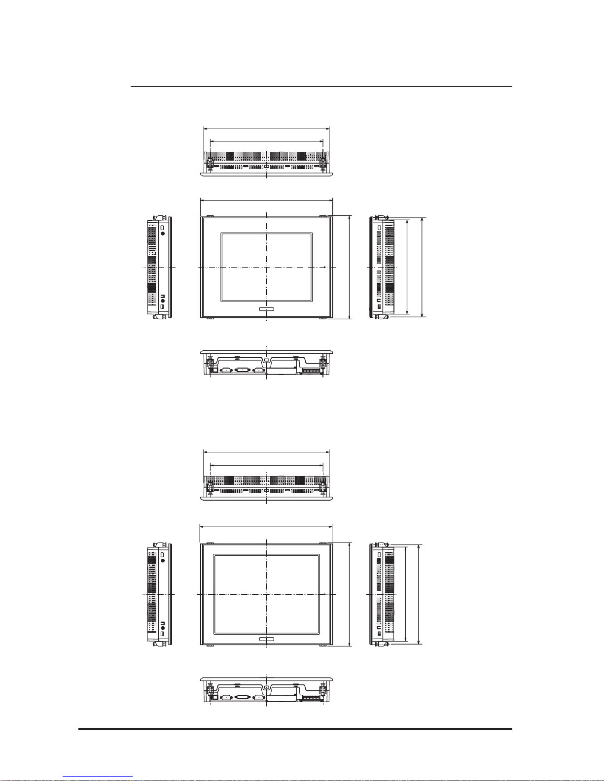
2.6 FP Dimensions
2.6.1 External Dimensions
FP-2600 Series
FP-2500 Series
301 [11.85]
317 [12.48]
243 [9.57]
8 [0.31]
58 [2.28]
227 [8.94]
Unit:mm [in.]
Top
Front Side
301 [11.85]
317 [12.48]
243 [9.57]
8 [0.31]
58 [2.28]
227 [8.94]
Top
Front Side
Unit:mm [in.]
Page 35
FP-2500/FP-2600 Series User Manual
2.6 FP Dimensions
2-16
2.6.2 External Dimensions (with Installation Fasteners)
FP-2600 Series
FP-2500 Series
270 [10.63]
249 [9.80]
239 [9.41]
317 [12.48]
301 [11.85]
227 [8.94]
Top
Front Right
Left
Bottom
Unit : mm [in.]
270 [10.63]
249 [9.80]
239 [9.41]
317 [12.48]
301 [11.85]
227 [8.94]
Top
Front Right
Left
Bottom
Unit:mm [in.]
Page 36

FP-2500/FP-2600 Series User Manual
2.6 FP Dimensions
2-17
2.6.3 Installation Fasteners
2.6.4 FP Panel Cut Dimensions
Panel
301.5 [11.87 ]
+1
0
+0.04
0
227.5
[8.96 ]
+0.04
0
+1
0
under 4-R3
Unit: mm [in.]
• Panel thickness should be between 1.6mm [0.06in.] and
10.0mm [0.4in.]. Panel’s thickness should be based on
the level of panel strength required.
• Check that the installation panel or cabinet's surface is
flat, in good condition and has no jagged edges.
• If desired, metal reinforcing strips can be attached to
the inside of the panel, near the Panel Cut, to increase
the panel’s strength.
3.1.1 Installation Procedure
• Be sure to create the correct sized panel cut required to
install the FP, using the installation dimensions given.
FP
Panel Cut
11
[0.43]
16 [0.63]
31 [1.22]
19.5 [0.77]
M5
10f
Unit : mm [in.]
Page 37

FP-2500/FP-2600 Series User Manual
2-18
Memo
Page 38

FP-2500/FP-2600 Series User Manual
3-1
3.1 Installation
3.1 Installation
Chapter 3
Installation and Wiring
1. Installation
2. Wiring
3. Operation Mode Setup
and Display Positioning
3.1.1 Installation Procedures
Follow the steps given below when installing the FP .
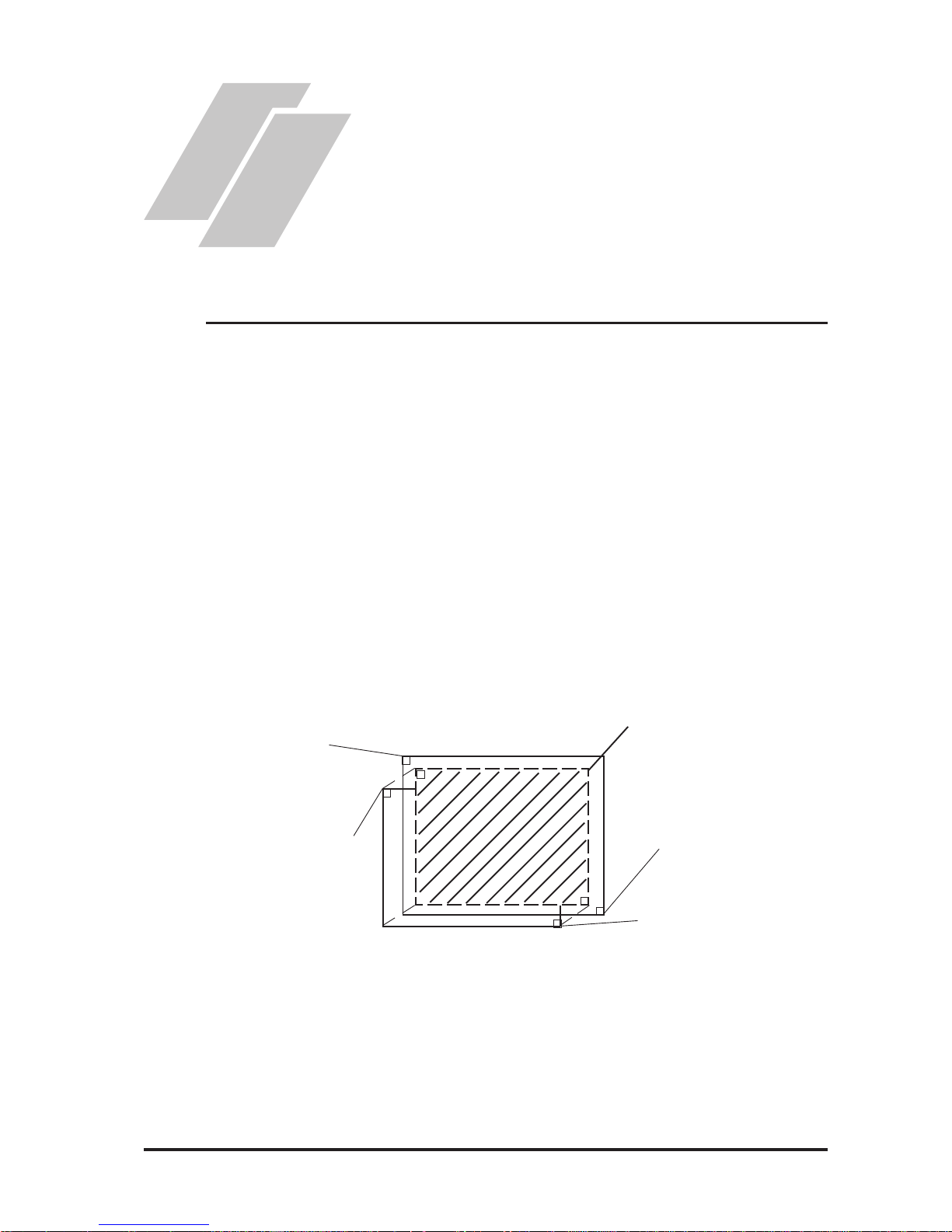
Check the Installation Gasket’s Seating
It is strongly recommended that you use the installation gasket, since it absorbs vibration
in addition to repelling water.
Place the FP on a level surface with the display panel facing downward. Check that the
FP unit’s installation gasket is seated securely into the gasket’ s groove, which runs
around the perimeter of the panel’s frame.
For details about installing the gasket, refer to
• Before installing the FP into a cabinet or panel, check that the installation gasket is securely attached to the unit.
• A gasket which has been used for a long period of time may have
scratches or dirt on it, and can lose much of its dust and drip resistance. Be sure to change the gasket periodically (or when scratches
or dirt become visible).
• Be sure to use gasket model GP570-WP10-MS.
• Be sure the gasket's seam is not inserted into any of the unit's corners, only in the straight sections of the groove. Inserting it into a
corner may lead to its eventually tearing.
• To ensure the installation gasket’s maximum level of moisture resistance, be sure the gasket’s seam is inserted as shown into the panel’s
bottom face.
6.1.2 Installation Gasket Check/Replacement
Gasket
Rear face
Page 39

FP-2500/FP-2600 Series User Manual
3-2
3.1 Installation
Creating a Panel Cut
Create the correct sized opening required to install the FP , using the installation dimensions given.
• Check that the installation panel or cabinet's surface is flat, in good
condition and has no jagged edges. Also, if desired, metal reinforcing
strips can be attached to the inside of the panel, near the Panel Cut, to
increase the panel’s strength.
• Panel thickness should be from 1.6mm [0.06in.] to 10.0mm [0.4in.].
Decide the panel’s thickness based on the level of panel strength required.
For easier maintenance, operation, and improved ventilation, be sure to
install the FP at least 100 mm [3.94 in.] away from adjacent structures
and other equipment.
2.6.4 FP Installation Dimensions
The installation gasket, installation fasteners and attachment screws are all required
when installing the FP .
Side View
Rear View
100
[3.94]
100
[3.94]
100
[3.94]
100
[3.94]
100
[3.94]
100
[3.94]
100
[3.94]
Panel
Panel Cut
Unit: mm [in.]
1.6mm [0.06in.] to 10.0mm [0.4in.]
> <
Page 40

FP-2500/FP-2600 Series User Manual
3-3
3.1 Installation
• Be sure that the ambient temperature and the ambient humidity are
within their designated ranges. (When installing the FP in a cabinet or
enclosure, the term “ambient temperature” indicates the cabinet or
enclosure’s internal temperature.)
• Be sure that heat from surrounding equipment does not cause the FP
to exceed its standard operating temperature.
• When installing the FP in a slanted panel, the panel face should not
incline more than 30o.
• When installing the FP in a slanted panel, and the panel face inclines
more than 30o, the ambient temperature must not exceed 40 oC. You
may need to use forced air cooling (fan, A/C) to ensure the ambient
operating temperature is 40 oC or below.
Panel
Face
Panel
Interior
NO more than 30 degrees of tilt
Page 41

FP-2500/FP-2600 Series User Manual
3-4
3.1 Installation
Installing the FP
1) Insert the FP into the panel cut,
as shown here.
2) Insert the installation fasteners
into the FP unit’s insertion slots,
at the top and bottom of the
unit. (total:4 slots)
3) Insert each of the fasteners as
shown right. Be sure to pull the
fastener back until it is flush
with the rear of the attachment
hole.
Panel
FP
Panel Cut
Bottom
Insertion Slots
Top
Installation panel
Hook
Page 42

FP-2500/FP-2600 Series User Manual
3-5
3.1 Installation
Do not use too much force, since it may damage the FP
unit. A torque of only 0.5 N•m is sufficient to tighten
these screws.
4) Use a Phillips screw driver to
tighten each fastener screw and
secure the FP in place.
• Depending on the panel condition, you can improve moisture resistant effect by
increasing the number of installation fasteners.
• Installation fasteners are sold by your local FP distributor.
Page 43

FP-2500/FP-2600 Series User Manual
3-6
3.2 Wiring
• Wherever possible, use thick wires (max 2mm2) for power terminals, and twist
the exposed wire ends when connecting the Ring Terminals.
• Please use the following size crimp-on type Ring Terminals.
3.2 Wiring Cautions
3.2.1 Connecting the Power Cord
• To prevent the Ring Terminals from causing a short when the ter-
minal block attachment screws are loosened, be sure to use sleevetype Ring Terminals.
• When the FG terminal is connected, be sure the wire is grounded.
Not grounding the FP unit will result in excessive noise. Use your
country’s applicable standard for grounding.
3.2.3 Grounding
• The SG and FG terminals are connected internally in the FP unit.
• When connecting the SG line to another device, be sure that the
design of the system/connection does not produce a shorting loop.
WARNINGS
• To avoid an electric shock, when connecting the FP
unit's power cord terminals to the power terminal
block, confirm that the power supply is completely
turned OFF, via a breaker, or similar unit.
• FP2500-T12 and FP2600-T12 units are designed to
use only AC100V to AC240V input. FP2500-T42-24V
and FP2600-T42-24V units are designed to use only
DC24V input. Any other power level can damage both
the FP and the power supply.
• Since there is no power switch on the FP unit, be sure
to attatch a breaker-type switch to its power cord.
• Be sure to ground the FP’s FG terminal. Failure to do
so can lead to an electrical shock or FP malfunction.
Page 44

FP-2500/FP-2600 Series User Manual
3-7
3.2 Wiring
1) Confirm that that the FP unit's Power Cord is unplugged from the power supply.
2) Use a screwdriver to remove the Power Input Terminal Block's clear plastic cover .
3) Unscrew the screws from the middle three (3) terminals, align the Ring Terminals and
reattach the screws.
4) Replace the Power Input T erminal Block's clear plastic cover.
• Confirm that the ring terminal wires are connected correctly.
• A torque of only 0.5 to 0.6 N•m is required to tighten an attachment screw.
L
AC Input Live Line
N
AC Input Neutral Line
FG
Grounding Terminal connected to
the FP chassis.
Power
Terminal
Block
Connecting the Power Supply Terminals
FP2500-T12/FP2600-T12
+
Positive electr ode
-
Negative electrode
FG
Grounding Terminal connected to
the FP chassis.
Power
Terminal
Block
FP2500-T42-24V/FP2600-T42-24V
L N FG
L N FG
+ - FG
+ - FG
Page 45

FP-2500/FP-2600 Series User Manual
3-8
3.2 Wiring
3.2.2 Connecting the USB Cable Strap Attachment
USB Cable Strap Attachment Procedure
1) Insert the USB cable into the USB connector.
2) Tighten the strap until the cable is secured in place and insert the cable strap into the
cable strap holder as shown in the following figure.
USB Cable Strap Removal Feature
1) Push in the cable strap's stopper with a standard flat-blade screwdriver until the cable
strap band is unlocked, and remove the strap.
2) Disconnect the USB cable.
Stopper
USB Cable Strap Holder
USB Cable
USB Cable Holder
<A>
• If the stopper will not move, press on <A> (shown in figure) to free the strap
from the strap holder.
Page 46

FP-2500/FP-2600 Series User Manual
3-9
3.2 Wiring
3.2.3 Connecting the Power Supply
• When supplying power to the FP unit, be sure
to separate the input/output and operation unit
lines, as shown.
• T o increase the noise resistance quality of the
power cable, be sure to twist each power wire
before attaching the Ring T erminal.
• The power supply cable must not be bundled or
positioned close to main circuit lines (high
voltage, high current), or input/output signal lines.
• Connect a lightning surge absorber, as shown in
the diagram, to deal with power surges.
• T o avoid excess noise, make the power cable as
short as possible.
• Be sure to ground the
surge absorber (E1)
separately from the FP
unit (E2).
• Select a surge absorber
that has a maximum
circuit voltage greater
than the power supply's
peak voltage.
Input/ Output Power
power
input/output
main circuit
Motor
Operation
Unit
Input/ Output Power
FP unit
Main
Power
FP
power
FP unit
lightning
surge
absorber
input/output unit
Main
Power
FP
power
FP unit
Page 47
FP-2500/FP-2600 Series User Manual
3-10
3.2 Wiring
3.2.4 Precautions: Grounding
other
equipment
FP unit
FP unit
other
equipment
FP unit
other
equipment
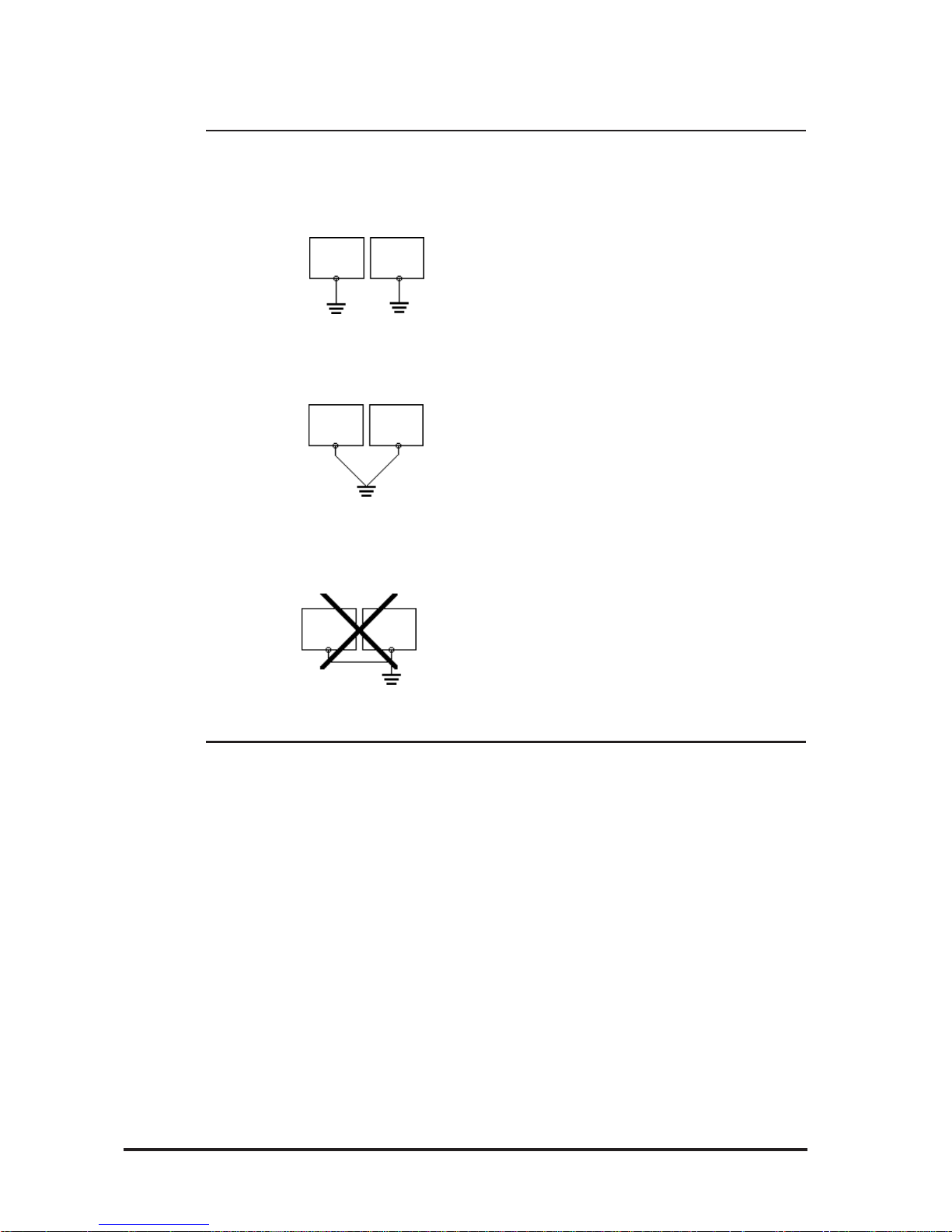
(a) Exclusive grounding (BEST)
(b) Common grounding (OK)
(c) Common grounding (BAD)
3.2.5 Precautions: Input/Output Signal Lines
• Input and output signal lines must be separated from operating circuit power cables.
If this is not possible, use a shielded cable and connect the shield to the FP chassis.
• Connect the FP unit's FG terminal to
an exclusive ground. [diagram (a) Grounding resistance of under 100Ω.]
• If exclusive grounding is not possible,
use a common connection point.
[diagram (b)]
• The grounding wire should have a
cross sectional area greater than
2mm2. Make the connection point as
close to the FP unit as possible, and
make the wire as short as possible.
When using a long grounding wire,
replace the thin wire with a thicker
wire placed in a duct.
• If this equipment does not function
properly when grounded, disconnect
the ground wire from the FG terminal.
Page 48

FP-2500/FP-2600 Series User Manual
4-1
4.1.1 Dip Switch Preset Settings and Adjustments
4.1 Operation Mode Setup
Chapter 4
Setting up and Adjusting the FP unit
1. Operation Mode Setup
2. Screen Display Adjustment
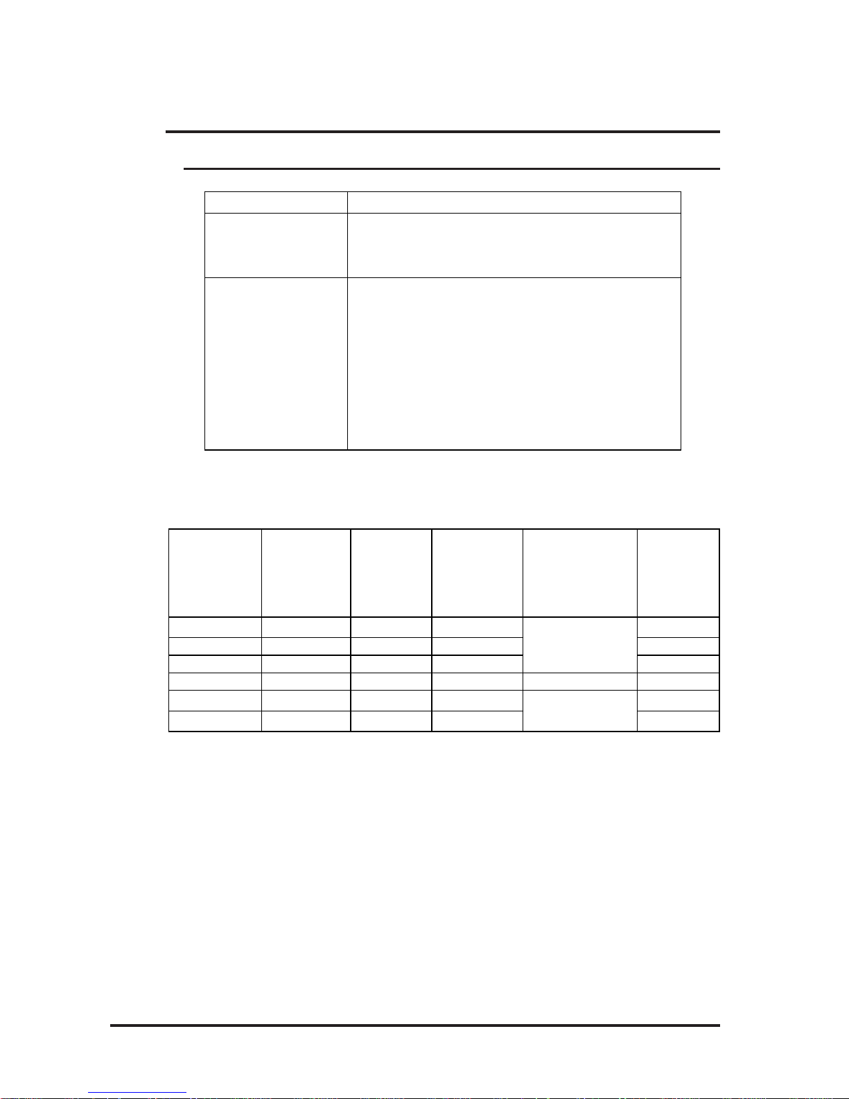
The FP unit's dip switches are located behind the Dip Switch Cover.
ON
SW1
86543271
SW
No.
Function Description
Factory
Settings
1-1
Switch between USB and RS232C for touch panel data
transmission.
Used to set the touch panel data input (command
control) method to either USB or RS-232C.
ON : USB
OFF : RS-232C (Default setting)
1-2 Display/hide the OSD.
Used to display or hide the OSD.
ON : Hide
OFF : Display (Default setting)
1-3
1-4
1-5
Switch between analog RGB
and DVI-D input.
Used to change the image input method.
ON : DVI-D
OFF : analog RGB (Default setting)
1-6
1-7
1-8
All OFF
Reserved Set this switch to OFF
Reserved Be sure these switches are always set to OFF
Dip Switches
Dip switch settings are effective only when starting up the FP unit.
After changing any dip switch settings, be sure to restart your FP unit.
Page 49

FP-2500/FP-2600 Series User Manual
4-2
4.1 IOperation Mode Setup
Starting the OSD
T o start the OSD and enter OSD mode, press the three corners of the touch panel in
the following order ((1)upper left, (2)upper right and (3)lower right) within 5 seconds. In
OSD mode, the setting screen is displayed in the center of the screen and the touch
panel cannot be used to communicate with external devices until the OSD setup is
completed.
4.1.2 Status of Front LED in Operation Modes
OFF
(Not Lit)
Green Orange
Green/
Red Flash
Orange
Flash
Pow e r OFF Power ON Pow er ON Powe r ON P o we r ON
- Normal Normal Burned-out Burned-out
-YesNoYesNo
Panel
Backlight
Image Input
LED
4.2.1 Calibration of OSD Display Position
“V***” indicates the OSD version.
Using the OSD
The setting screen uses icons to (select and) enter settings. When you start up the OSD,
the main menu appears. T ouching an icon displays its submenu or setting change screen.
In the setting screen, and icons are used to change the setting. To apply the setting,
press the button. Press the button to save the defined settings.
Simply touch the touch panel to call up the OSD (On Screen Display) screen.This
screen allows you to perform detailed display adjustment.
4.2 Screen Display Adjustment
OSD is not displayed when DIP SW 1-2 is ON.
OSD Setting screen
1
2
3
Page 50

FP-2500/FP-2600 Series User Manual
4-3
4.2 Screen Display Adjustment
CONTRA ST Adjusts the contrast.
(Analog RGB only)
*1
BLACK LEVEL Adjust s t he color bright nes s .
(Analog RGB only)
*1
H-POS
V-POS
(Analog RGB only)
*1
(Analog RGB only)
*1
BA CKLIGHT
(Analog RGB only)
*1
DISPLAY MODE
OSD CLEAR (RESET)
OSD SAVE
SY STEM
ESCAPE
Cancels the s et ting and returns to the up per level. In the main
menu, this command closes t he OSD.
Save the current value and quit the OSD.
Changes settings s uch as activating t he click sound .
Reset s t he current OS D value to t he default value.
A u t omatically adjus t s t he contr as t and t he bright ne ss .
PHASE
Display s t he r esolut ion of t he input image data.
A UTO GAIN CONTROL
Item Function
Adjust s t h e backlight br ightness. (9 levels)
A d justs t he input s ignal and t he do t clock position. ( 32 levels)
A djusts the vertical position of the screen.
A djust s t he horizontal position of the s creen.
H-SIZE
A d justs t he s creen size in the horizontal direction.
* 1 When using DVI-D, the message "DO NOT NEED SETUP FOR DVI-D" is displayed
and no settings are required.
Quitting the OSD
T o quit the OSD, press the button in the main menu or leave the OSD as it is for at
least 30 seconds. If the OSD is automatically closed after 30 seconds of inactivity , the
values set before the OSD was closed will be applied.
4.2.2 OSD Setting Icons
Page 51

FP-2500/FP-2600 Series User Manual
4-4
4.2 Screen Display Adjustment
Main menu
CONTRAST
Adjustment buttons
Applies the setting and then returns to the main menu.
Cancels the setting and then returns to the main menu.
Sets the contrast setting and then moves to the sub contrast menu.
Sub contrast R
Adjustment buttons
Applies the setting and then returns to the
Sub contrast adjustment screen.
Cancels the setting and then returns to the
Sub contrast adjustment screen.
Sub contrast G
Sub contrast B
H-SIZE
Adjustment buttons
Applies the setting and then returns to the
Sub contrast adjustment screen.
Cancels the setting and then returns to the
Sub contrast adjustment screen.
Adjustment buttons
Applies the setting and then returns to the
Sub contrast adjustment screen.
Cancels the setting and then returns to
the Sub contrast adjustment screen.
Adjustment buttons
Applies the setting and then returns to the main menu.
Cancels the setting and then returns to the main menu.
4.2.3 OSD Setting Item Details
V-POS
Adjustment buttons
Applies the setting and then returns to the main menu.
Cancels the setting and then returns to the main menu.
H-POS
Adjustment buttons
Applies the setting and then returns to the main menu.
Cancels the setting and then returns to the main menu.
BLACK LEVEL
Adjustment buttons
Applies the setting and then returns to the main menu.
Cancels the setting and then returns to the main menu.
Returns to the contrast adjustment screen
Page 52

FP-2500/FP-2600 Series User Manual
4-5
4.2 Screen Display Adjustment
BACKLIGHT
AUTO GAIN CONTROL (Analog RGB only)
Starts the auto gain control and then automatically returns to the
main menu.
DISPLAY MODE
Returns to the main menu.
OSD CLEAR
Clears the setting.
Cancels the setting and then returns to the main menu.
PHASE
Adjustment buttons
Applies the setting and then returns to the main menu.
Cancels the setting and then returns to the main menu.
Adjustment buttons
Applies the setting and then returns to the main menu.
Cancels the setting and then returns to the main menu.
Be sure to perform auto gain control when the screen has both 100%
black and 100% white areas displayed.
SYSTEM
Enables/disables the click sound. With this
parameter, the sound level can also be
adjusted.
(Default value: OFF <Click sound disabled>)
When an input data resolution of 720 x 400 is
used in the VGA text mode, set this parameter
to ON. For other resolutions, set this
parameter to OFF.
(Default: OFF)
2.3.1 Analog RGB Interface
Returns to the main menu.
Page 53

FP-2500/FP-2600 Series User Manual
4-6
4.2 Screen Display Adjustment
Applies the setting and returns to the main menu.
Cancels the setting and returns to the main menu.
Enables/disables the Backlight burnout detect
function.
(Default: ON )
When a burned-out backlight is detected, the
status LED flashes alternately green and red, or a
steady orange.
T ouch-operation will be disabled when the
backlight burns out, which prevents the FP from
sending input signals to the PLC.
Normally , the FP unit detects a backlight
burnout by monitoring the backlight's
current flow , however, the FP may fail to
detect this condition, depending on the
type of backlight problem.
Enables/disables the screen display Auto OFF
function and sets the time when the Auto OFF
function is enabled.
(Default: OFF <Auto OFF function disabled>)
The Auto OFF function automatically turns off the
display to prevent the screen from burning out
when the touch panel is not used for some period
of time. With this parameter, you can set the time
interval to turn off the screen display (how much
time passes before the screen display is turned
off) when the touch panel is not used. If the touch
panel is not touched over the set time, the
backlight will automatically turns off.
Select the time period from 1 min, 3 min, 5 min,
10 min, and OFF (Auto OFF function disabled).
In this screen, touching the value displayed on the panel changes the value of
the time period.
If an analog RGB interface is used and the
horizontal display position exceeds the
normally adjustable range, setting the POLARITY LOCK feature to ON may allow you to
adjust the display position. (Default: OFF
<Disabled>)
This setting is enabled after the OSD is
closed.
Page 54

FP-2500/FP-2600 Series User Manual
4-7
4.2 Screen Display Adjustment
SAVE Saves all the adjusted settings in the EEPROM.
• In the OSD, pressing the button applies the set value and enables
the setting. The set value won't be canceled unless the power is turned
OFF or the value is reset.
If the power is turned OFF without saving the set value, that data will
disappear . The last saved data will be read into the system when the
FP starts. To enable the changed value, be sure to press the SAVE but-
ton.
• When the OSD automatically closes after 30 seconds of inactivity, the
set value that you were modifying at the time will be retained. If you
quit the OSD using the button, the value you were modifying will
be ignored and the previously set value will remain in effect.
Page 55

FP-2500/FP-2600 Series User Manual
4-8
Memo
Page 56
5-1FP-2500/FP-2600 Series User Manual
5.1 Touch Interface Data
Chapter 5
Touch Panel Data
5.1 Touch Interface Data
1. Touch Interface Data
2. Touch Panel Communication
Program for MS-DOS
®
The FP-2500/FP-2600 Series units use an analog type touch panel. This touch panel
needs a calibration program to adjust the actual touch position.
Touch Panel Coordinate Data
The screen display origin point, with 640 x 480 for FP-2500 Series units and 800 x 600
for FP-2600 Series units, is normally at the upper left corner of the screen. Therefore, a
software to convert the touch coordinates to display coordinates is needed.
(1) Resolution
Both the X and Y coordinates have a resolution of 1024.
The origin point (0,0) is located in the upper left corner of the screen.
Display Coordinates
(0,0)
Touch Panel
Coordinates
(1023,1023)
Touch Panel
Coordinates
(0,0)
Display Coordinates
(640,480)
Display Area
Page 57

5.1 Touch Interface Data
5-2 FP-2500/FP-2600 Series User Manual
(2) Data Format
T ouch Panel coordinate data is sent to the host using the following format.
All data is in binary format.
Header: 1 byte (11h= touched; 10h = released)
X coordinate: 2 bytes (0 to 3FFh)
Y coordinate: 2 bytes (0 to 3FFh)
<Example> If the coordinate (X=23(11h), Y=500(1F4h)) is touched and moved to
the coordinate (X=63(3Fh), Y=250(F Ah)).
11h 0h 17h 1h F4h touched
11h 0h 17h 1h F4h continuous output with the same location
11h 0h 18h 1h F3h moving without releasing touch
11h 0h 3Fh 1h FAh continuous data output unless finger is released
11h 0h 3Fh 1h FAh 10h when released, only 1 unit of data is sent
Added when touch is released.
X coordinate
Y coordinate
11h
10h
Page 58

5-3FP-2500/FP-2600 Series User Manual
5.1 Touch Interface Data
Coordinate Data Conversion Software
OS Touch Panel Ha ndl er Ca l i bra tion
Windows
®
95,
Windows
®
98,
WindowsNT
®
4.0,
Windows
®
2000,
Windows
®
XP
MS-DOS
®
FPATPH.EXE
*2*3
FPCALIB.EXE
*2*3
Mouse Emulator V2
(PL-TD000)
*1
* 1 Mouse Emulator V2 (PL-TD000) is optional software. This program is used for
both English and Japanese.
Mouse Emulator V2 cannot automatically detect your PC COM Port used
to connect the FP unit.
As a result, select your PC COM Port via the Mouse Emulator V2 Installer window and enter the settings given in this manual for the Allocated I/O address and Interrupt.
When changing the COM Port on your PC used to connect the FP unit,
change the setting using Window's [Start]-[Program]-[Updd]-[Operation
Setup]-[Hardware].
* 2 These programs are contained in the CD-ROM.
About CD-ROM
* 3 These programs are only for the FP-2500 Series units. FP-2600 Series units
cannot used.
5.2 Touch Panel Communication Programs for MS-DOS
®
Page 59

5.1 Touch Interface Data
5-4 FP-2500/FP-2600 Series User Manual
5.2 T ouch Panel Communication Programs For MS-DOS
®
When using MS-DOS® on the FP-2500 Series units, MS-DOS® T ouch Panel Communication Programs for MS-DOS® are required. These programs are contained in the
CD-ROM.
CD-ROM Data
• These programs run only on PC/AT compatible machines using MSDOS. Therefore, do not use a USB cable.
• These programs are only for FP-2500 Series units. FP-2600 Series
units cannot be used.
• When using a host device that does not have a CD-ROM Drive unit, copy
these programs to a floppy disk.
5.2.1 FP ATPH.EXE (Touch Panel Handler)
FPATPH [parameter] or FPATPH -r
* Parameter Explanation
-a <n>Selects the I/O address of the SIO port where the touch panel
is connected.
(hexadecimal, default = 2f 8)
n = 3f 8 (COM1)
2f 8 (COM2)
-q <n>Selects the interrupt level (IRQ) for the SIO port where the touch
panel is connected. (default = 3)
n = 4 (COM1)
3 (COM2)
-i<n> Sets the vector number for the function call's software interrupt.
(hexadecimal, default = 59)
-r Removes the current (resident) memory command.
-c <path> Specifies the data file made by FPCALIB.EXE (touch panel data
FPcalibration) that contains the correction value.
"FPATPH. CAL" in the current directory is selected for default.
How to Operate the Software
Page 60
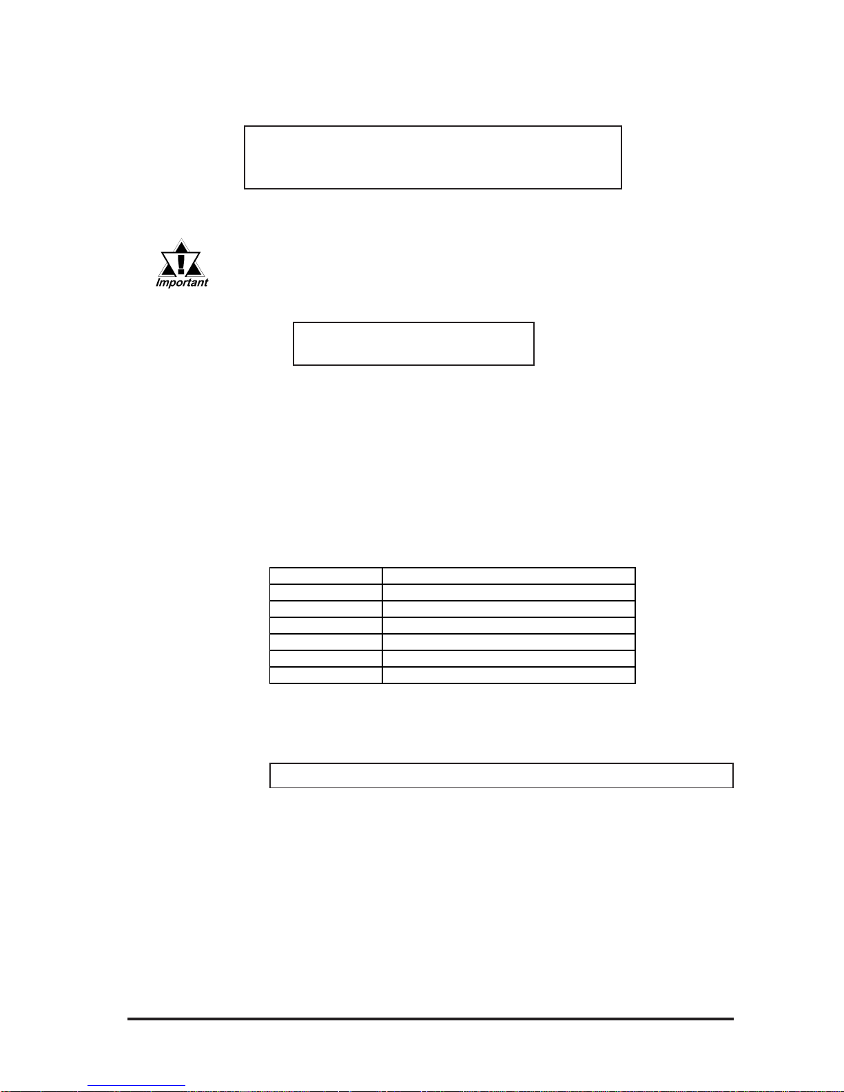
5-5FP-2500/FP-2600 Series User Manual
5.1 Touch Interface Data
When this program runs, the following message will display on the screen.
Analog T ouch Panel Handler FPA TPH. EXE Version 1.**
Copyright (c) 1993 Digital Electronics Corporation
Stay resident.
After execution, the command stays in memory .
When the data file made by FPCALIB. EXE is not found or cannot be
opened, the following message appears. In such a case, the program
will run without data correction.
WARNING ! ! Can't open CAL file.
Stay resident.
If data correction is not carried out successfully, the display position may
not match with the touch panel input position.
Function
FP A TPH. EXE has the following functions, which are activated by software
interrupt (Default = INT59H) function calls.
< INT 59H Function List >
Function Explanation
Function 8100h Touch panel input ( infinite wait)
Returns touch coordinates. W aits infinitely for input.
< input > AX = 8100h
< output > AH = 0 : normal termination
BX = Y : coordinate ( 0 - 479 )
DX = X : coordinate ( 0 - 639)
CX = Number of effective input buffers for the analog touch panel.
Function Code Contents
8100h Touch panel input (infinite wait)
8101h Touch panel input (instant return)
8102h Non-destructive input
0200h Input buffer clear
8500h Detection of touch panel's condition
FE00h Resident Confirmation
Page 61

5.1 Touch Interface Data
5-6 FP-2500/FP-2600 Series User Manual
Function 8101h Touch panel input ( instant return )
Returns touch coordinates. Will quit the function if there is no input.
< input > AX = 8101h
< output > AH = 0 : input
1 : no-input
BX = Y : coordinate ( 0 - 479 )
DX = X : coordinate ( 0 - 639)
CX = Number of effective input buffer for the analog touch panel.
Function 8102h Non-renewing touch panel input
Sends the position coordinates, and does not renew the panel's input buffer .
< input > AX = 8102h
< output > AH = 0 : input
1 : no-input
BX = Y : coordinate ( 0 - 479 )
DX = X : coordinate ( 0 - 639)
CX = Number of effective touch panel input buffers.
Function 8500h Detection of touch panel condition
Returns the touch panel condition
< input > AX = 8500h
< output > AH = status at 640 x 480 mode
Bit 1 Bit 0
Contents
0 0
touched
0 1
no-change
1 0
(not used)
1 1
released
Function 0200h Input buffer clear
Clears the touch panel's input buffer .
< input > AX = 0200h
< output > AH = 0 : normal end
Page 62

5-7FP-2500/FP-2600 Series User Manual
5.1 Touch Interface Data
Function FE00h Confirmation of resident memory
If FP ATPH.EXE is resident in memory, a fixed message and its version number
are returned.
< input > AX = FE00h
< output > AH = 0 : normal termination
BL = 'Y'
BH = 'B'
CX = version number
FPATPH.EXE
discrimination
number
Version number
Carry = clear
Page 63

5.1 Touch Interface Data
5-8 FP-2500/FP-2600 Series User Manual
5.2.2 FPCALIB.EXE (T ouch Panel Data FPCalibration)
Because of changes in operational environment and the unit's deterioration, differences in theoretical and actual touch coordinates arise; and therefore these differences must be corrected periodically , via a utility software called FPCALIB.EXE
(touch panel data FPcalibration).
By touching the designated position on the display (upper left and lower right),
FPCALIB.EXE calculates the difference between the theoretical and actual coordinates. Then, from the result, a correction data file to be used by FPATPH (touch
panel handler) is made.
How to Operate
FPCALIB -d [ parameter ]
* Explanation of parameters
-a <n> Selects the I/O address of the SIO port where the touch panel is connected.
(hexadecimal, default = 2f 8)
n = 3f 8 (COM1)
2f 8 (COM2)
-q <n> Selects the interrupt level (IRQ) for the SIO port where the touch panel is
connected. (default = 3)
n = 4 (COM1)
3 (COM2)
-c <path> Specifies the data file made by FPCALIB.EXE (touch panel data
FPcalibration) that contains the correction value.
Operation Procedure
When the touch panel is connected to COM2, the default value can be used.
When FPCALIB. EXE is executed, the message on the left
displays on the screen. Then the
two designated position, upper
left and lower right corners,
starts to blink.
Analog Touch Panel Calibration FPCALIB.EXE
Version 1.**
Copyright(c)2000 Digital Electronics Corporation
Calibration Mode
Touch upper left and lower right cornner of the
screen.
[Enter] : Go to test mode.
[Esc] : Terminate program.
Upper left Lower right
(0000,0000) (0000,0000)
1)
Page 64

5-9FP-2500/FP-2600 Series User Manual
5.1 Touch Interface Data
T ouch the desigated positions, one after
the other. Correction data will be
calculated from the difference between the
actual and the theoretical values.
The actual value is shown on the display.
2)
Press the [Esc] key to terminate
the program. Press the [Y] key
after the message on the left is
shown, and the program will
terminate without saving any
FPcalibration data. If the [N] key
is pressed, the system will return
to "FPcalibration mode".
3)
4)
Enter the file name
When the data filename is specified from the parameter (-C=
[path]) during the execution of
FPCALIB.EXE, the program will
terminate without showing the message on the left.
Analog Touch Panel Calibration FPCALIB.EXE
Version 1.** Copyright (c) 2000 Digital
Electronics Corporation
Calibration Mode
Touch upper left and lower right corner of the
screen.
[Enter : Go to test mode.
[Esc] : Terminate program.
Upper left Lower right
(0039.0026) (0997.0988)
Terminate program without saving calibration data?(Y/N)
Calibration data name? FPATPH.CAL_
• Do not touch two points at the
same time.
• T ouch right above the designated
position.
• By re-touching the points, the actual coordinates will redisplay .
The "test mode" tests whether the
FPcalibration has been processed
correctly or not. To enter "test mode",
press the [Enter] key .
The FPcalibration is confirmed as successful if the locus shown on the display
matches as touched. Otherwise, return
to the "FP calibration mode" and redo the
FPcalibration by touching the right blinking position.
Press the [Esc] key to return to
"FPcalibration mode".
If the test result is OK, press the [Enter]
key. After the following message appears,
enter the name of the data file and press
the [Enter] key .
Analog Touch Panel Calibration FPCALIB.EXE
Version 1.**
Copyright(c)2000 Digital Electronics Corporation
Test Mode
[Enter] : Save calibration data and Exit.
[Esc] : Return to calibration mode.
Page 65

5-10 FP-2500/FP-2600 Series User Manual
Memo
Page 66

FP-2500/FP-2600 Series User Manual 6-1
6.1 Troubleshooting
Chapter 6
Troubleshooting
1. Troubleshooting
2. Error Message
This section assumes that the FP is the cause of a problem, not the host.
• When the host is the problem, please refer to its corresponding manual.
Possible types of trouble while using this unit are as follows.
Screen does not display normally
• No display appears after the unit is switched on.
• The screen disappears during standard operation.
• The screen does not display normally .
Touch panel does not respond
• The touch panel does not respond when pressed.
• The touch panel reaction time is abnormally long.
6.1.1 Possible Device Problems
Page 67

FP-2500/FP-2600 Series User Manual
6.1 Troubleshooting
6-2
When the screen does not display when powering up, or if the screen turns OFF by
itself, use the flowchart below to find an appropriate solution.
6.1.2 No Display
No Screen Display
YES
Does the backlight
(CCFL) light up?
YES
NO
NO
Turn OFF the power switch.
NO
YES
Is it using the correct
power voltage?
Is the power supply
cable connected properly
to the unit?
There is a problem with the FP
unit. Please contact your local
FP distributor.
Fix the power cable connection.
Chapter 3. Instal-
lation and Wiring
Connect the appropriate voltage.
Chapter 2. Specifi-
cations
Is the dip switch SW1-5
connected to the input
interface.
NO
YES
Set the Dip Switch correctly . After
changing any dip switch settings, be
sure to restart your FP unit.
4.1.1 Dip Switch
Preset Settings and
Adjustments
Page 68

FP-2500/FP-2600 Series User Manual 6-3
6.1 Troubleshooting
Does the screen display
correctly?
YES
NO
NO
Is the computer operating?
Start the computer .
YES
NO
Is the RGB cable/
DVI-D cable connected
correctly?
Connect the RGB cable/DVI-D
cable correctly .
2.4 Cable Diagrams
Adjust the screen display position.
4.2 Screen Display
Addjustment
There is a problem with the FP
unit. Please contact your local
FP distributor.
YES
YES
NO
Are the FP output
settings the same as the
PC's frequency and
resolution?
Set the FP output settings so that
they match the PC's frequency and
resolution.
Page 69

FP-2500/FP-2600 Series User Manual
6.1 Troubleshooting
6-4
6.1.3 Touch Panel Does Not Respond
T ouch panel not working
Is the SIO or USB cable
connected correctly?
NO
There is a problem with the FP
unit. Please contact your local
FP distributor.
When the touch panel does not react, or its reaction is very slow after it is pressed,
follow the flowchart below to find the origin of the problem and the appropriate solution.
Connect the SIO or USB cable
correctly .
2.4 Cable Diagrams
YES
Is the dip switch SW1-1
connected to the input
interface.
NO
YES
Set the Dip Switch correctly .
4.1.1 Dip Switch
Setting
Is T ouch Panel Driver set
correctly?
NO
Set the Touch Panel Driver Correctly.
5.2 T ouch Panel
Communication Programs For
MS-DOS® or PL-TD000
Installation Guide.
YES
Is T ouch Panel Driver
installed?
NO
Install the T ouch Panel Driver.
5.2 T ouch Panel
Communication Programs For
MS-DOS® or PL-TD000
Installation Guide.
YES
Page 70

FP-2500/FP-2600 Series User Manual 6-5
6.2 Error Message
6.2 Error Message
This section explains the messages that appear when an error has occurred in the
FP unit during RUN mode. The problem causing the error message and its
related countermeasure are explained in the table below .
(Only the latest error message will appear on the FP screen)
6.2.1 Error Message List
Error Mes s age Problem Countermeeas ure
Signal timing has been input that is not
compatible with the FP unit.
The dot clock has greatly exceeded of the FP
unit's usable timing range.
Resolution has been set that is not compatible
with the FP unit.
The PS-2000B unit or a Windows-compatible
PC's power has not been turned ON.
Turn on the PS-2000B unit or a Windows-
compatible PC's power.
The PS-2000B unit or a Windows-compatible
PC has not been correctly connected to the FP
unit.
Connect the RGB cable/DVI-D cable correctly.
The input I/F and the image input signal type
are not the same.
Set the Dip Switch correctly.
4.1.1 Dip Switch Preset
Settings and Adjustments
Out of Range 1 to 3
No Signal
Set the FP output settings so that they match the
PC's frequency and resolution.
2.3 Interface Specifications
Page 71

FP-2500/FP-2600 Series User Manual6-6
Memo
Page 72

FP-2500/FP-2600 Series User Manual 7-1
7.1.1 Cleaning the Display
7.1 Regular Cleaning
Chapter 7
Maintenance
1. Regular Cleaning
2. Periodic Check Points
3. Backlight Replacement
When the display surface or frame become
dirty , use a soft cloth moistened with neutral
detergent to wipe away any dust or stains.
Do not clean the unit with thinner , organic
solvents, or strong acids.
Do not use sharp or hard objects, such as a
mechanical pencil or screwdriver, to push on
the display . This could damage the unit.
Attach the screen protection sheet when
using the FP in extremely dirty or dusty
areas.
Neutral
detergent
Protection sheet
Thinner
Organic solvent
Strong acid
Page 73

7.1 Regular Cleaning
FP-2500/FP-2600 Series User Manual
7-2
7.1.2 Installation Gasket Replacement
The installation gasket protects the FP and improves its water resistance. For instructions on installing the FP unit's gasket, refer to
Chapter 3 Installation and Wiring
A gasket which has been used for a long period of time
may have scratches or dirt on it, and could have lost
much of its water resistance. Be sure to change the
gasket at least once a year, or when scratches or dirt
become visible.
Installation Gasket Replacement Procedure
1) Place the FP on a flat, level
surface with the display facing
downwards.
2) Remove the old gasket from
the FP.
3) Attach the new gasket to the
FP. Be sure to insert the gasket
into the FP unit’s groove so
that the gasket’s groove sides
are vertical.
4) Check if the gasket is attached
to the FP correctly . The upper
surface of the gasket should
protrude approximately 2mm
out from the groove.
Page 74

FP-2500/FP-2600 Series User Manual
7-3
7.2 Periodic Check Points
• The gasket must be inserted correctly into the groove for the FP unit’s
moisture resistance to be equivalent to IP65f.
• Be sure the gasket's seam is not inserted into any of the unit's cor-
ners, only in the straight sections of the groove. Inserting it into a
corner may lead to its eventually tearing.
• The upper surface of the gasket should protrude approximately 2mm
out from the groove. Be sure to check that the gasket is correctly inserted before installing the FP into a panel.
T o keep your FP unit in its best condition, please inspect the following points periodically .
FP Operation Environment
• Is the ambient temperature within the allowable range (0oC to 50oC )?
• Is the ambient humidity within the specified range (30%RH to 90%RH, dry
bulb temperature of 39oC or less)?
• Is the operating atmosphere free of corrosive gasses?
Electrical Specifications
• Is the Rated V oltage Range appropriate ?
Related Items
• Are all power cords and cables connected properly? Have any become loose?
• Are all installation fasteners holding the unit securely?
• Are there any scratches or traces of dirt on the installation gasket?
7.2 Periodic Check Points
unit: mm [in.]
2.0 [0.08]
FP M odel Num ber Rate d V oltage Range
FP2500-T12
FP2600-T12
AC85 t o 264V
FP2500-T42-24V
FP2600-T42-24V
DC19.2 to 28.8V
Page 75

7.3 Backlight Replacement
FP-2500/FP-2600 Series User Manual
7-4
7.3 Backlight Replacement
The backlight is a cold-cathode tube. Although the FP uses a long-life backlight, replacement may be required earlier than expected depending on the environment where
the FP is used.
The life span of the backlight is as follows:
(Time period until the backlight becomes half as bright as a new one)
50,000 hours (approx. 5.7 years)
When a burned-out backlight is detected, the status LED flashes alternately green and
red, or a steady orange.
• To prevent an electric shock, be sure to turn the FP unit's
power OFF before replacing the backlight.
• The backlight and the FP itself will be very hot just after
turning off the power. To avoid burning your skin, be
sure to wear gloves when replacing the backlight.
• The backlight is very fragile. To avoid possible injury, do
not directly touch the glass or pull the cable.
• Normally, the FP unit detects a backlight burnout by monitoring the
backlight's current flow. However, the FP may fail to detect backlight
burnout, or may only detect it before the backlight burns out completely, depending on the type of backlight problem.
• Please check that the replacement backlight is compatible with the FP.
WARNINGS
FP M odel Rev. B ackli ght M odel
FP-2500 Series - GP577RT-BL00-MS
FP2600-T 12
Rev.1 is not marked.
*1
FP2600-T 42-24V
Rev.1 is not marked.
*1
FP2600-T 12
Rev.1 is marked.
*1
FP2600-T 42-24V
Rev.1 is marked.
*1
PS600-BU00
CA3-BLU12-01
*1 The corresponding backlight unit differs depending on FP-2600 Series unit's
marked Revision.
For more information on how to determine the revision version,
see "Revision Version" (Page 10).
Page 76

FP-2500/FP-2600 Series User Manual 7-5
7.3 Backlight Replacement
Backlight Replacement
Follow the procedures given below to replace the FP unit’s backlights. Be sure to wear
gloves during replacement.
• Be sure to protect the FP front panel’s surface to prevent damage.
• The FP-2500 Series units have an upper and a lower backlight. Be
sure to replace both.
• The FP-2600 Series units have only one backlight.
Page 77

7.3 Backlight Replacement
FP-2500/FP-2600 Series User Manual
7-6
1) Turn the FP unit’ s power OFF (i.e. disconnect the FP unit's power cord). Use
a Phillips screwdriver to remove the
case’ s seven (7) rear attachment screws
and USB holder. Pivot the rear cover
open, starting from the top of the unit.
• Be sure not to break the rear
cover’s four (4) alignment tabs
when you open it.
• To prevent FP unit damage, be
sure the FP unit's rear cover
open/close direction is correct.
2)The cover is fastened at the bottom,
and hinges open.
3)Loosen the three (3) circuit board attachment screws.
4)The circuit board is connected on one
side, and hinges open.
Rear Attachment Screws
Attachment
Screws
When the FP unit's power has
just been turned OFF, the circuit
board chassis is still very hot! Be
sure to wear gloves to prevent
being burned.
5)Disconnect the upper backlight's two
(2) power connectors.
Connectors
USB
holder
7.3.1 Replacing GP577RT-BL00-MS
Page 78

FP-2500/FP-2600 Series User Manual 7-7
7.3 Backlight Replacement
7) Remove the old backlight.
Attachment Screws
8) Insert the new backlight.
Upper Section
Lower Section
11) After both backlight units are changed
and the power connectors reattached,
close the rear case and reattach the case's
two attachment screws.
10)Reattach the backlight unit's power connector. Repeat these steps for the FP
unit's bottom backlight unit.
9) Insert the metal cover's three (3) position-
ing tabs into the LCD holder’s positioning slots. Next, insert and tighten the
cover's two (2) attachment screws.
The FP unit’s upper and lower backlights are different. Be sure to confirm that the backlight you are replacing is the correct unit by looking at
the side of the backlight connector.
6) Loosen the upper and lower backlight
holder attachment screws, and remove the
upper backlight unit's metal cover .
Since the attachment screws are
small, be sure not to lose them or
allow them to fall inside the FP's
case.
If the backlight has
an arrow here, it is
used only for the
upper backlight.
Positioning Tabs
Page 79

7.3 Backlight Replacement
FP-2500/FP-2600 Series User Manual
7-8
• Be sure not to pinch or cut any of the FP unit's internal wiring when
closing the case.
• If any of the attachment screws becomes misplaced, check to be sure
that they have not fallen inside the FP. If a screw has fallen inside the
FP, do not connect the unit’s power cord.
1) Turn the FP unit’ s power OFF (i.e. disconnect the FP unit's power cord). Remove the three (3) I/F covers, and use
a Phillips screwdriver to remove the
case’ s seven (7) rear attachment screws
and USB holder. Pivot the rear cover
open, starting from the top of the unit.
2)The cover is fastened at the bottom,
and hinges open.
3)Loosen the three (3) circuit board attachment screws.
• Be sure not to break the rear
cover’s four (4) alignment
tabs when you open it.
• To prevent FP unit damage, be
sure the FP unit's rear cover
open/close direction is correct.
Since the attachment screws
are small, be sure not to lose
them or allow them to fall inside
the FP unit's case.
Attachment
Screws
Rear Attachment Screws
USB holder
7.3.2 Replacing PS600-BU00
Page 80

FP-2500/FP-2600 Series User Manual 7-9
7.3 Backlight Replacement
8) Connect the backlight's two (2) power
connectors. Next, close the circuit board
and secure the rear case in place using
the attachement screws removed in steps
1), 2) and 3).
5) Disconnect the backlight's two (2) power
connectors.
6) Loosen the backlight unit attachment
screw (the screw cannot be separated
from the backlight unit), slide the backlight in the direction shown and remove it
from the FP.
7) Insert the new backlight in the FP. Insert
the unit by sliding it in the direction shown
in step 6), then, tighten the unit’s attachment screw.
Upper Section
Lower Section
Attachment
Screw
4) The circuit board is connected on one
side, and hinges open.
When the FP unit's power has
just been turned OFF , the circuit
board chassis is still very hot!
Be sure to wear gloves to prevent being burned.
Connector
Page 81

7.3 Backlight Replacement
FP-2500/FP-2600 Series User Manual
7-10
• Be sure not to pinch or cut any of the FP unit's internal wiring when
closing the case.
• If any of the attachment screws becomes misplaced, check to be sure
that they have not fallen inside the FP. If a screw has fallen inside the
FP, do not connect the unit’s power cord until it has been removed.
1) Turn the FP unit’ s power OFF (i.e. disconnect the FP unit's power cord). Remove the three (3) I/F covers, and use
a Phillips screwdriver to remove the
case’ s seven (7) rear attachment screws
and USB holder. Pivot the rear cover
open, starting from the top of the unit.
2)The cover is fastened at the bottom,
and hinges open.
3)Loosen the three (3) circuit board attachment screws.
• Be sure not to break the rear
cover’s four (4) alignment
tabs when you open it.
• To prevent FP unit damage, be
sure the FP unit's rear cover
open/close direction is correct.
Since the attachment screws
are small, be sure not to lose
them or allow them to fall inside
the FP unit's case.
USB holder
Rear Attachment Screws
Attachment
Screws
7.3.3 Replacing CA3-BLU12-01
Page 82

FP-2500/FP-2600 Series User Manual 7-11
7.3 Backlight Replacement
5) Disconnect the backlight's one (1) power
connector.
6) Loose the backlight unit attachment screw.
Next, slide the backlight in the direction
shown and lift it forward and remove it
from the FP.
4) The circuit board is connected on one
side, and hinges open.
When the FP unit's power has
just been turned OFF , the circuit
board chassis is still very hot!
Be sure to wear gloves to prevent being burned.
Connector
Attachment Screw
Page 83

FP-2500/FP-2600 Series User Manual
7-12
8) Connect the backlight's one (1) power
connector. Next, close the circuit board
and secure the rear case in place using
the attachement screws removed in steps
1), 2) and 3).
7) Insert the new backlight in the FP. Insert
the unit by sliding it in the direction shown
in step 6).
• Be sure not to pinch or cut any of the FP unit's internal wiring when
closing the case.
• If any of the attachment screws becomes misplaced, check to be sure
that they have not fallen inside the FP. If a screw has fallen inside the
FP, do not connect the unit’s power cord until it has been removed.
 Loading...