

Page 1

ESE50SDISolidStateDisk
UserGuide
Order Number: EK–ESE50–UG. B01
Page 2

June 1993
The information in this document is subject to change without notice and should not be construed
as a commitment by Digital Equipment Corporation. Digital Equipment Corporation assumes no
responsibility for any errors that may appear in this document.
The software described in this document is furnished under a license and may be used or copied
only in accordance with the terms of such licence.
© Digital Equipment Corporation 1992, 1993.
All Rights Reserved.
Printed in U.S.A.
The following are trademarks of Digital Equipment Corporation: Digital, HSC40, HSC60, HSC70,
HSC90, KDM, OpenVMS, RA, SA, SDI, VMS, and the DIGITAL logo.
All other trademarks and registered trademarks are the property of their respective holders.
This document was prepared using VAX DOCUMENT, Version 2.1.
Page 3

Contents
Preface ............................................................ v
1 Introduction
1.1 General Information. . ........................................ 1–1
1.1.1 Media Type, Model Byte, and Capacity . ....................... 1–3
1.2 Hardware Maintainability ..................................... 1–4
1.3 Dual-Port Capability . ........................................ 1–4
1.4 Drive-Resident Diagnostics Overview ............................ 1–5
1.5 User Precautions/Recommendations.............................. 1–5
1.5.1 Data Retention. . . ........................................ 1–5
1.5.2 Orderly Shutdown ........................................ 1–6
1.5.3 Recommended Operating Temperature . ....................... 1–7
1.5.4 Electrostatic Discharge Protection ............................ 1–7
1.6 ESE50 SSD Maintenance Strategy .............................. 1–9
1.7 ESE50 SSD Specifications ..................................... 1–9
2 Installation
2.1 Introduction ................................................ 2–1
2.2 Site Preparation and Planning. . ................................ 2–1
2.3 Unpacking ESE50 Add-Ons .................................... 2–2
2.4 Installing SDI Cables and Power Cords ........................... 2–4
2.4.1 Installing Internal SDI Cables ............................... 2–4
2.4.2 Installing Internal Power Cords.............................. 2–4
2.4.3 Installing External SDI Cables .............................. 2–4
2.5 Power and Safety Precautions . . ................................ 2–5
2.6 AC Power Wiring ............................................ 2–7
3 Operating Instructions
3.1 Introduction ................................................ 3–1
3.2 OCP Functions, Switches, and Indicators . . ....................... 3–1
3.3 Powerup Diagnostics . ........................................ 3–2
3.3.1 Problems at Powerup ...................................... 3–2
3.3.2 Operator Control Panel Lamp Testing . . ....................... 3–2
3.3.3 Testing Spin-Up Drive ..................................... 3–3
3.4 Programming the Drive Unit Address ............................ 3–4
3.5 ESE50 Operating Modes ...................................... 3–6
3.5.1 Normal Mode Setup ....................................... 3–6
3.5.2 Fault Display Mode Setup . . ................................ 3–6
3.5.3 Test Mode Setup . ........................................ 3–8
iii
Page 4

4 Diagnostics
4.1 General Information. . ........................................ 4–1
4.2 Drive-Resident Diagnostics .................................... 4–1
4.2.1 Powerup Resident Diagnostics ............................... 4–2
4.3 Test Selection from the OCP . . . ................................ 4–2
A Customer Equipment Maintenance
A.1 Customer Responsibilities ..................................... A–1
A.1.1 Cleaning Supplies ........................................ A–1
A.1.2 Ongoing Equipment Care . . . ................................ A–2
A.1.3 Monthly Equipment Maintenance ............................ A–2
A.1.4 Maintenance Records ...................................... A–2
Index
Figures
1–1 ESE50 Solid State Disk .................................... 1–2
1–2 Typical ESE50 SSD Subsystem Configuration ................... 1–4
1–3 ESE50 Dual-Port Configuration .............................. 1–5
1–4 ESD Wrist Strap . ........................................ 1–8
2–1 ESE50 Disk Drive Packaging ................................ 2–3
2–2 881 Power Controller (Example) ............................. 2–6
2–3 Electrical Plug Configurations ............................... 2–8
3–1 ESE50 OCP ............................................. 3–2
3–2 Unit Address Programming Flowchart. . ....................... 3–5
3–3 Fault Display Example .................................... 3–7
3–4 Fault Mode Flowchart ..................................... 3–7
3–5 ESE50 Test Display ....................................... 3–8
3–6 Running Test OCP Display . ................................ 3–8
4–1 Test Selection Flowchart . . . ................................ 4–3
A–1 Customer Equipment Maintenance Log . ....................... A–3
Tables
1–1 SDI SSD Capacity ........................................ 1–3
1–2 Summary of Data Retention Times ........................... 1–6
1–3 Specifications for the ESE50 SSD ............................ 1–9
1–4 Additional Electrical Specifications by Model for the ESE50 SSD .... 1–10
iv
Page 5

Preface
This manual contains the following information:
• ESE50 solid state disk specifications
• Environmental considerations
• Installation information and references
• Start-up procedures
• Acceptance testing criteria
• Troubleshooting procedures
Although this manual is written primarily for ESE50 solid state disk customers,
installation procedures described or referenced in this manual are intended for
Digital Customer Services engineers performing original installation of the ESE50
solid state disk. Qualified Customer Services engineers must be trained in the
following:
• ESE50 solid state disk
• DSA concepts
• ESD procedures
This manual does not cover cabinet cable routing and connections. Specific
information concerning subsystem cabinet-related procedures can be found in
product-specific manuals. A list of related documentation follows:
Document Title Order Number
SA300/SA350 Storage Array Family Configuration Guide EK–SA300–CG
SA600/SA800 Storage Array Family Configuration Guide EK–SA600–CG
SA650/SA850 Storage Array Family Configuration Guide EK–SA650–CG
SAxxx Storage Array Family Configuration Guide EK–SAxxx–CG
Conventions Used in This Guide
The following conventions are used in this guide:
Note — Notes provide general information on the current topic.
Caution — Cautions provide information to prevent damage to equipment or
software. Read these carefully.
Warning — Warnings contain information to prevent personal injury. Read these
carefully.
v
Page 6

Page 7

1.1 General Information
The ESE50 solid state disk (SSD) is a member of the Digital Storage
Architecture/Standard Disk Interconnect (DSA/SDI) family, and is plugcompatible with all DSA/SDI controllers.
The ESE50 solid state disk is a random access low latency mass storage device
that uses DRAM semiconductor technology for fast response time. The ESE50 is
Digital’s fastest disk drive and is used when I/O response time is a key metric.
The ESE50 is contained in a half rack (RA92 style) enclosure with its own power
and data retention capabilities. It connects and operates on the standard disk
interface (SDI) and may be used with controllers implementing this bus. The
operator control panel (OCP) from the RA9x disk drive is also used on the ESE50
SSD. The ESE50 can also be packaged in any SA3xx, SA6xx, SA8xx, or SA9xx
storage array cabinet.
The following controllers support the ESE50:
• HSC (40/60/65/70/90/95)
• KDM70
1
Introduction
The ESE50 has been tested under OpenVMS Versions 5.4 and 5.5. Under these
versions, the ESE50 is identified as a DU device (rather than by the ESE50
name). Identification as a DU device does not impact any standard Digital disk
functionality. Shadowing, failover, dual porting, bound volumes, and so forth are
supported.
However, when running the ESE50 under OpenVMS Versions 5.4-n, 5.5, or 5.5-1,
key things to be aware of are:
• All shadow sets must be comprised of the same capacity ESE50 units.
• Controller-based volume shadow sets require manual verification that all
members of the shadow set are on the same controller.
The ESE50 is fully supported under OpenVMS Version 5.5-2 and OpenVMS AXP
Version 1.5 (and all subsequent releases).
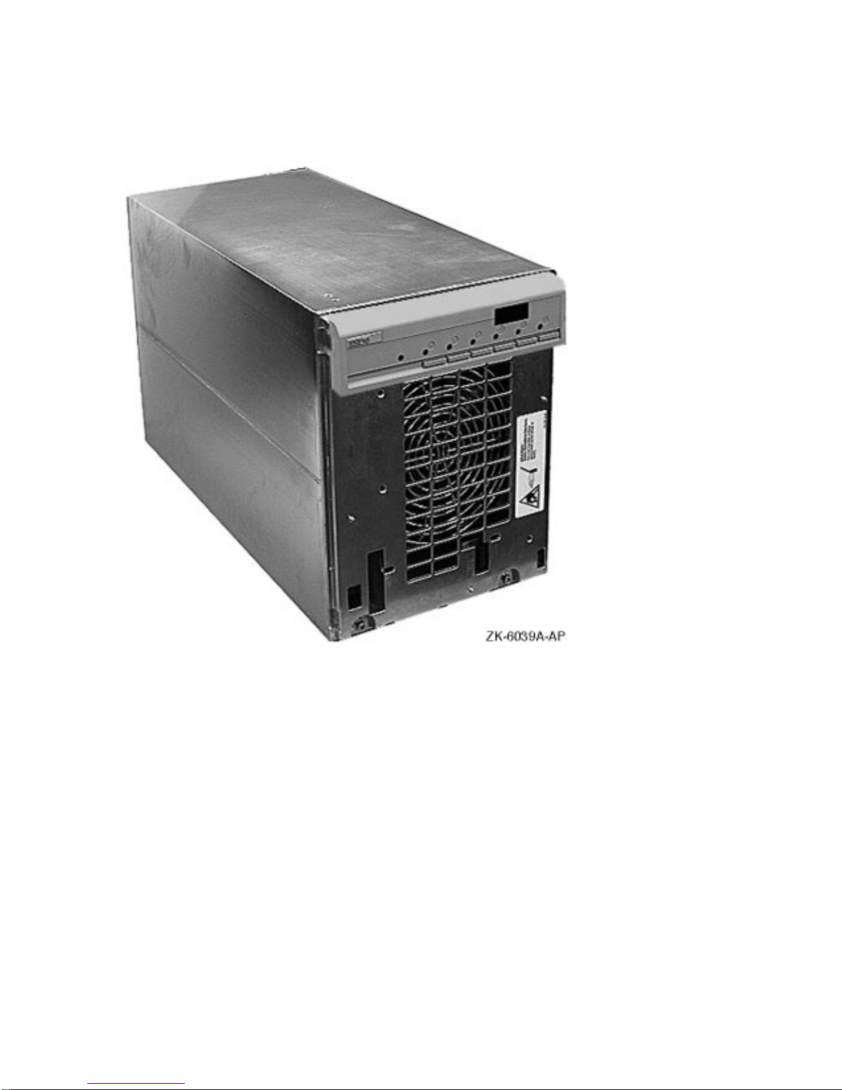
Figure 1–1 shows an ESE50 solid state disk.
Introduction 1–1
Page 8
Introduction
1.1 General Information
Figure 1–1 ESE50 Solid State Disk
1–2 Introduction
Page 9

1.1.1 Media Type, Model Byte, and Capacity
The ESE50 has a unique media type and model byte depending on the capacity.
This is done for operating system compatibility.
Option Media Type Model Byte Capacity (LBNs)
ESE50–AA,AB ESE52 31 238080
ESE50–BA,BB ESE56 48 1196544
ESE50–DA,DB ESE58 49 1915392
The storage medium for the ESE50 SSD are 4M bit DRAMs and the data is
accessed in 512-byte blocks. The formatted capacity of the ESE50 option is shown
in Table 1–1.
Table 1–1 SDI SSD Capacity
1
Option
ESE50–Ax 2 128.0 MB 121.9 MB 465 238080
ESE50–Bx 10 640.0 MB 612.6 MB 2337 1196544
ESE50–Dx 16 1024.0 MB 980.6 MB 3741 1915392
No. of
Arrays
Unformatted
Capacity
Formatted
Capacity
Introduction
1.1 General Information
No. of
LBN Cyl’s
No. of
Logical
Blocks
1
"x" equals "A" for 120 Vac or "B" for 240 Vac.
The ESE50 has the following common characteristics:
• 20.0 megabits/second transfer rate
• Full data retention
• Extensive resident microcode diagnostics
• Internal error log capabilities
• Multifunction OCP
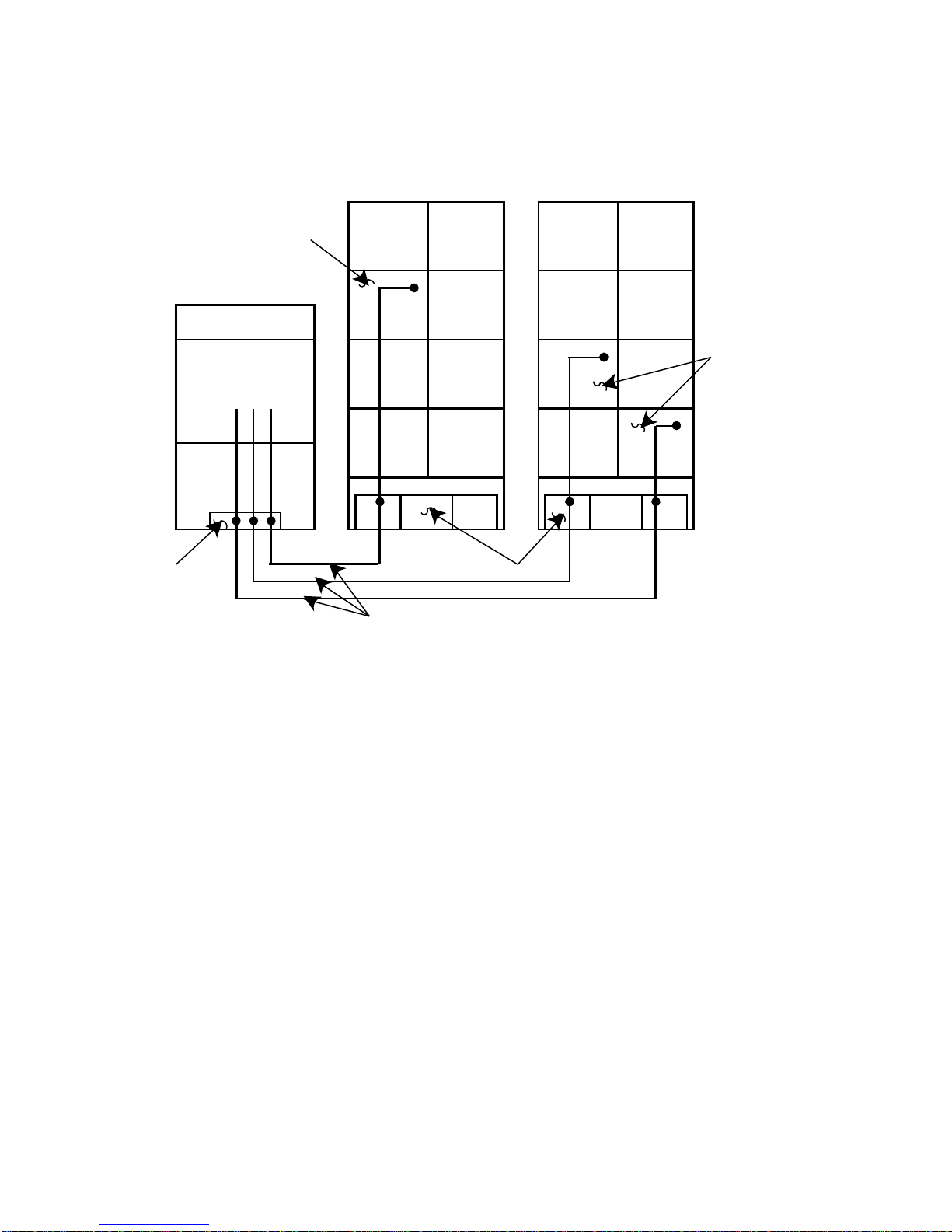
Figure 1–2 represents a typical ESE50 SSD subsystem configuration including an
SDI controller.
Introduction 1–3
Page 10
Introduction
1.1 General Information
Figure 1–2 Typical ESE50 SSD Subsystem Configuration
DRIVE CABINET DRIVE CABINET
ESE50
CONTROLLER A
SDI CONTROLLER A
ESE50
I/O BULKHEAD
SDI CABLES
1.2 Hardware Maintainability
The ESE50 SSD uses modular field replaceable units (FRUs) for easy access
and servicing. An extensive set of drive-resident microcode diagnostics and a
drive-resident error log help simplify problem isolation.
1.3 Dual-Port Capability
Ports are enabled by the port select switches (A or B) on the front of the OCP.
With both port switches selected, the ESE50 operates in a static dual-port mode.
Static dual porting means that an SSD is shared between two controllers but is
on line to only one controller at a time for data transfers. The second controller
must wait until the drive is available before placing the drive on line.
An additional SDI cable is required for dual porting. Figure 1–3 shows an ESE50
dual-port configuration.
I/O BULKHEAD
1–4 Introduction
Page 11
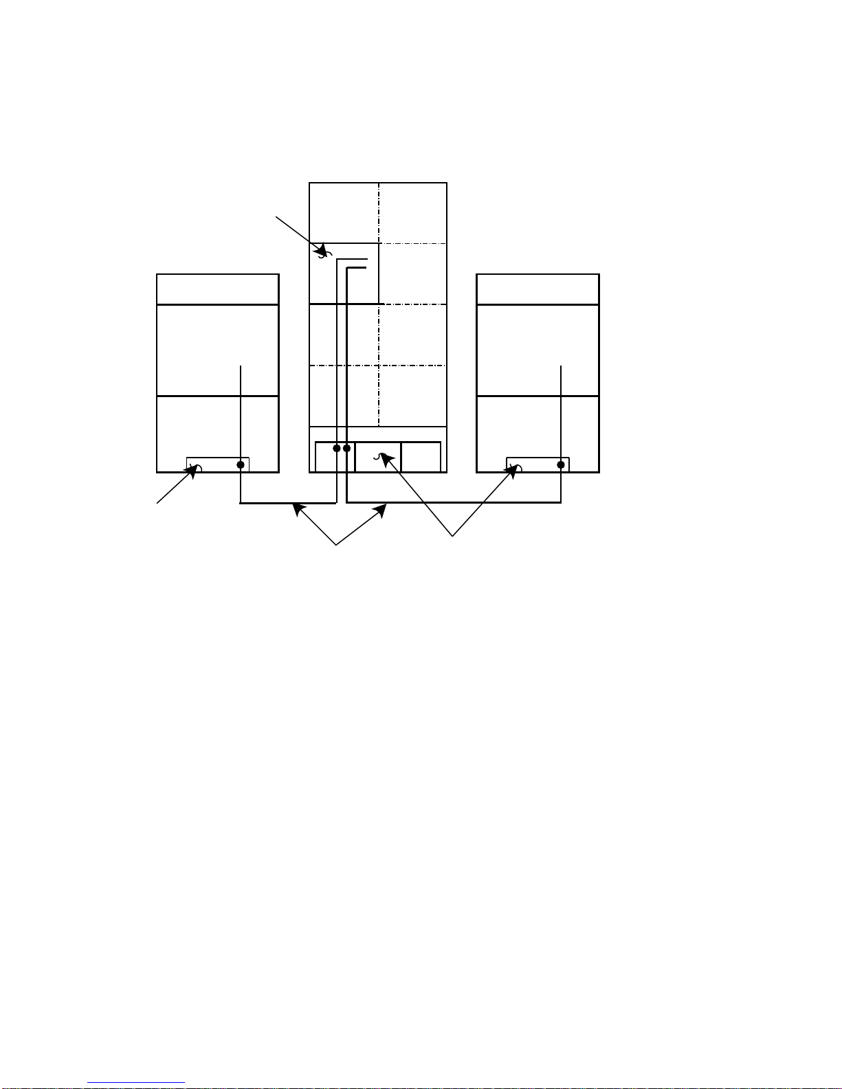
Figure 1–3 ESE50 Dual-Port Configuration
DRIVE CABINET
ESE50
PORT
CONTROLLER A
A
B
Introduction
1.3 Dual-Port Capability
CONTROLLER B
SDI CONTROLLER A
I/O BULKHEAD
SDI CABLES
I/O BULKHEAD
SDI CONTROLLER B
1.4 Drive-Resident Diagnostics Overview
Drive-resident diagnostics run during powerup and spin-up cycles to test basic
drive functions.
Patrol diagnostics run periodically during normal operations.
Drive-resident diagnostics can be run from the OCP while the drive is off line.
See Chapter 4 for a list of drive-resident diagnostics.
1.5 User Precautions/Recommendations
Digital recommends that certain precautions be taken to protect equipment
and user data. These precautions involve data backup methods, recommended
operating temperatures, and electrostatic discharge protection, and are described
in this section.
1.5.1 Data Retention
The ESE50 provides data nonvolatility through the use of an integrated data
retention system. This data retention system is comprised of a controller, an
SCSI magnetic Winchester disk drive, and batteries. Data retention is invoked
only when ac power is lost to the ESE50 unit during normal operation. In this
situation, the batteries will power the unit while all data in the memory arrays
is transferred to the Winchester disk drive. If ac power is restored any time
during the transfer process, then the ESE50 unit is instantly available. On Rev.
A and B ESE50 units, the ESE50–AA/AB (120 MB) and ESE50–BA/BB (600 MB)
options contain the complete data retention system. On Rev. C ESE50 units, the
Introduction 1–5
Page 12

Introduction
1.5 User Precautions/Recommendations
ESE50–AA/AB (120 MB), ESE50–BA/BB (600 MB), and ESE50–DA/DB (1 GB)
options options contain the complete data retention system.
Table 1–2 lists the data retention times.
Table 1–2 Summary of Data Retention Times
Data
ESE50 Option Revision
ESE50_AA/AB A or B 120 MB 90 seconds 120 seconds 8
ESE50_BA/BB A or B 600 MB 360 seconds 390 seconds 2
ESE50_AA/AB C 120 MB 60 seconds 90 seconds 16
ESE50_BA/BB C 600 MB 300 seconds 360 seconds 4
ESE50_DA/DB C 1 GB 480 seconds 540 seconds 3
†A two-hour battery recharge period is required afterward. Power failure exceeding this duty cycle
may result in data loss.
Although the ESE50 provides nonvolatile features, it is the user’s responsibility
to protect data by using proper backup procedures similar to backup of magnetic
disks. The following backup methods are recommended for an ESE50:
Retention
Time
Backup
Time Start Time
Maximum Number of
Complete Backups
(Within Two-Hour
Period)†
• File duplication
This method normally involves copying the data onto removable media, such
as magnetic tape.
• Journaling
This method is recommened for files up to the last checkpoint or backup.
A data retention operation does not occur when the ESE50 main ac power
switch, located on the rear panel, is turned off. A data retention operation
is invoked automatically only when ac power is lost to the input power
cord. Refer to Section 1.5.2 for the orderly shutdown procedures.
1.5.2 Orderly Shutdown
To shut down an ESE50–AA/AB, –BA/BB (Rev. A, B, or C) , or –DA/DB (Rev. C)
system and to preserve data within the data retention system, the following
procedures are recommended:
1. Dismount the ESE50 unit from the OpenVMS operating system without
using the /NOUNLOAD qualifier. Wait for the RUN indicator to extinguish
(approximately six minutes) while data is transferred to the ESE50 internal
Winchester disk.
Caution
2. Press the RUN/STOP button out, and wait for the RUN indicator to
extinguish (approximately six minutes) while data is transferred to the
ESE50 internal Winchester disk.
1–6 Introduction
Page 13

1.5 User Precautions/Recommendations
Caution
The ESE50 data retention system should never be considered a substitute
for a site-specific data backup policy. The ESE50 should be treated as any
other master media in this regard.
1.5.3 Recommended Operating Temperature
The ESE50 SSD is designed to operate in a Class A environment.
1.5.4 Electrostatic Discharge Protection
Electrostatic discharge (ESD) is caused by the buildup and release of static
electricity. An electrical charge from a person or object can damage hardware
components and result in premature device or option failure.
Caution
To avoid product damage, always use ESD grounding straps when
handling static-sensitive modules and components.
Introduction
Use the following guidelines when handling static-sensitive components and
modules:
• Read all instructions and installation procedures included with the static
control materials and kits.
• Wear a properly grounded ESD wrist strap when handling modules,
components, or static-sensitive devices. Figure 1–4 shows an ESD wrist
strap in use.
When using an ESD wrist strap:
Ensure that the wrist strap fits snugly for proper conductivity.
Attach the alligator clip securely to a clean, unpainted, grounded metal
surface, such as the drive or cabinet chassis.
Do not overextend the grounding cord.
• Use static-protective containers to transfer modules and components
(including bags and tote boxes).
Introduction 1–7
Page 14

Introduction
1.5 User Precautions/Recommendations
Figure 1–4 ESD Wrist Strap
1–8 Introduction
Page 15

1.6 ESE50 SSD Maintenance Strategy
1.6 ESE50 SSD Maintenance Strategy
It is recommended that only trained Digital Customer Services engineers attempt
to service an ESE50 SSD.
To repair an ESE50, replace the FRU. An extensive set of drive-resident
microcode diagnostics and a drive-resident error log help simplify problem
isolation. A listing to all ESE50 FRUs is contained in the ESE50 Electronic
Storage Element Service Guide.
Appendix A describes the customer’s equipment maintenance responsibilities.
1.7 ESE50 SSD Specifications
Table 1–3 lists the data organization, performance, physical, electrical, and
environmental specifications of the ESE50 electronic storage element.
Table 1–3 Specifications for the ESE50 SSD
Data Organization ESE50–Ax ESE50–Bx ESE50–Dx
Storage capacity, formatted 120.0 MB 612.6 MB 980.6 MB
Storage capacity, unformatted 128.0 MB 640.0 MB 1024 MB
User logical cylinders 465.0 2337 3741
Cylinder/group 1 1 1
Tracks/group 128 128 128
Sector/track 4 4 4
Number of logical blocks 238,080 1,196,544 1,915,392
Introduction
Performance
Access time 0.25 milliseconds
Transfer rate 20.0 Mbits/sec
Single Start/Stop Time
Start† 90 to 540 seconds (capacity dependent)
Stop 60 to 480 seconds (capacity dependent)
Physical Dimensions
Height 26.56 cm (10.42 inches)
Width 22.19 cm (8.74 inches)
Depth 46.99 cm (18.50 inches)
Weight (maximum) 24.95 kg (55 pounds)
†Starting time is slightly longer due to powerup diagnostics.
(continued on next page)
Introduction 1–9
Page 16

Introduction
1.7 ESE50 SSD Specifications
Table 1–3 (Cont.) Specifications for the ESE50 SSD
Power Requirements
Standards UL listed; CSA certified; FCC Class A verified
Voltage 120/208 Vac at 60 Hz; Single-phase WYE
Inrush Current:
Running current:
Power factor:
Operating Environment
220/240 Vac at 50 Hz
5.08 amperes peak @ 132 Vac
2.31 amperes peak @ 264 Vac
1.87 amps @ 120 Vac
1.105 amps @ 220–240 Vac
0.65 @ 120 Vac
0.57 @ 220–240 Vac
Temperature 15 to 32°C (59 to 90°F)
Maximum allowable operating temperature is reduced by a factor
of 1.8°C/1000 m (1°F/1000 ft) for operation at high altitude sites
Relative humidity 20 to 80%
Maximum wet bulb 25°C (77°F)
Minimum dew point 2°C (36°F)
Table 1–4 contains additional electrical specifications by model for the ESE50
SSD.
Note
The ESE50 is not line-frequency dependent.
Table 1–4 Additional Electrical Specifications by Model for the ESE50 SSD
Nominal
Model Voltage Startup Current Power Dissipation
ESE50 120v 2.4A 300w (max)
ESE50 240v 1.5A 300w (max)
1
Currents are for nominal voltages of 120 Vac phase to neutral or for 240 Vac phase to neutral. For
101 Vac and 220 Vac nominal voltages, the drives will have proportionately higher phase currents by
a ratio of 120/101 or 240/220 to the currents specified in this table.
Input Current (Amps)
1
1–10 Introduction
Page 17

2.1 Introduction
This chapter describes site preparation and planning considerations and
procedures for unpacking the ESE50. Cabling, safety precautions, and voltage
selection are also discussed.
2.2 Site Preparation and Planning
Site preparation and planning are necessary before installing an ESE50 or
subsystem. Consider the following:
• Power Requirements: The ESE50 SSD use a single-phase power supply;
however, operating voltages are supplied through an 881, 874, H405, or other
applicable (system-specific) power controller.
• Thermal Stabilization: Thermal stabilization prevents temperature
differences between the equipment and its environment from damaging drive
components. Equipment must be placed in its operating environment at least
24 hours before operation.
2
Installation
Caution
The thermal stabilization procedure is mandatory. Failure to do this may
cause premature equipment failure.
• Environment: The ESE50 SSD must be operated in an environment where
the ambient air particle count does not exceed 500,000 particles (larger
than 0.5 micron) per cubic foot of air. Refer to Chapter 1 for additional
environmental specifications.
• Floor Loading: Consider placement and calculate the total weight of your
subsystem. An ESE50 weighs approximately 24.95 kg (55 pounds).
• Operating Temperature and Humidity: The required relative humidity
range is between 10 percent and 90 percent, with a minimum wet bulb
temperature of 28°C (82°F) and a minimum dew point of 2°C (36°F)
(noncondensing) with a step change of 10 percent or less.
The ESE50 can be operated in temperatures ranging from 10°C to 40°C (50°F
to 104°F). However, it is recommended that the ESE50 be operated in a
temperature below 25°C (77°F) to increase reliability and extend product life.
Installation 2–1
Page 18

Installation
2.3 Unpacking ESE50 Add-Ons
2.3 Unpacking ESE50 Add-Ons
Check packaging for external damage. Read and save any packing information.
Unpack the ESE50 SSD using the following procedure (Figure 2–1):
1. Cut and remove the shipping straps.
2. Open the shipping container.
3. Remove and save all packing material surrounding the disk drive.
4. Lift the disk drive from the shipping container.
ESE50s weigh approximately 24.95 kg (55 pounds) each and must be
handled with care.
Do not use the cardboard handles to lift the disk drive from the shipping
container. Injury to personnel or damage to equipment could result if the
cardboard handles are used for this purpose.
5. Once the mandatory thermal stabilization period has elapsed, remove the
barrier bag surrounding the disk drive.
Warning
Caution
The thermal stabilization procedure is mandatory. Failure to do this may
cause premature equipment failure.
2–2 Installation
Page 19

Figure 2–1 ESE50 Disk Drive Packaging
Installation
2.3 Unpacking ESE50 Add-Ons
Installation 2–3
Page 20

Installation
2.4 Installing SDI Cables and Power Cords
2.4 Installing SDI Cables and Power Cords
Use this section as a reference only. For detailed procedures and illustrations,
refer to subsystem-specific documentation.
Most fully configured cabinets have internal SDI cables and power cords in place.
However, when installing an ESE50 unit in an SA900 cabinet, the CK-SA900-L2
installation kit is required. Internal SDI cables are connected to the rear I/O
bulkhead located at the base of the cabinet.
Drive power cords are connected to the 881 (or system-specific model) power
controller located behind the rear I/O bulkhead at the bottom of the cabinet.
Figure 2–2 shows the 881 power controller, used with some ESE50 storage array
products, as viewed from the rear of the cabinet. Drive power cords are routed
through the grommeted cord opening in the front of the power controller, then
plugged into the rear power receptacles of the power controller.
Note
For a list of related documentation, refer to the preface in the front of this
manual. The list supplies titles and Digital part numbers of subsystem
manuals that contain specific ESE50 SSD system cabling and power cord
information.
2.4.1 Installing Internal SDI Cables
Internal SDI cables are installed at the factory for all drive positions in most
subsystem configurations (with exception of the SA900). Refer to subsystemspecific documentation for details about internal SDI cable routing, connections,
and availability.
2.4.2 Installing Internal Power Cords
Internal power cords are installed at the factory and connected to existing drives
and the power controller for your system. Connect add-on drive power cords using
the illustrations and procedures found in your system-specific documentation.
2.4.3 Installing External SDI Cables
When installing external SDI cables from the I/O bulkhead to the host, refer
to system-specific documentation for procedures and illustrations of bulkhead
port configurations. Many systems have an I/O port label adhered to the rear
door/panel of the system.
2–4 Installation
Page 21

2.5 Power and Safety Precautions
The ESE50 does not present any unusual fire or safety hazards. However, it
is recommended that you check ac power wiring for the computer system to
determine adequate capacity for expansion. To protect personnel and equipment,
ensure that power sources meet the specifications required for this equipment.
Hazardous voltages are present inside the ESE50. Installation and
service must be performed by trained Digital Customer Services
personnel. Bodily injury or equipment damage may result from incorrect
servicing.
Installation
2.5 Power and Safety Precautions
Warning
Installation 2–5
Page 22

Installation
2.5 Power and Safety Precautions
Figure 2–2 881 Power Controller (Example)
BUS/OFF/ON SWITCH
(CLOCKWISE FROM TOP)
POWER CONTROL
BUS CONNECTORS
POWER
CONTROLLER
FUSE
LABEL
CIRCUIT
BREAKER
POWER CORD
STRAIN RELIEF
GROMMETED
CORD
OPENING
J10
J11
J12
J13
UNDELAYED
DELAYED
(0.5 SEC)
I
CB
O
POWER
FUSE
CORD
SERIAL/LOGO
LABEL
CXO-2136A
2–6 Installation
Page 23

2.6 AC Power Wiring
Three-phase power must be present to support the installation of the 60-inch
cabinet. The 40-inch cabinet requires single-phase power. Check system-specific
documentation for the power requirements for your system.
The wiring used by Digital Equipment Corporation conforms to UL, CSA, and
ISE standards. Figure 2–3 shows the ac plug configurations for the ESE50s and
the 881 and 874 power controllers.
Do not apply power to the power controller until proper voltage has been
selected.
Installation
2.6 AC Power Wiring
Note
Installation 2–7
Page 24

Installation
2.6 AC Power Wiring
Figure 2–3 Electrical Plug Configurations
POWER CORDS GOING TO POWER CONTROLLER
120V 60HZ
POWER CORD
DEC NO. A-PS-1700083-23
PLUG - POWER CONTROLLER END
240V 50HZ
POWER CORD
DEC NO. A-PS-1700083-24
PLUG - POWER CONTROLLER END
120/240V 47-63HZ
10A/6A
POWER CORD
DEC NO. A-PS-1700442-18 OR
A-PS-1700442-19
PLUG - DRIVE END
PLUGS GOING TO WALL OUTLET (FROM CONTROLLER)
120V 60HZ
24A
1-PHASE
40-INCH
CABINET
60-INCH
CABINET
220/240V 50-60HZ
16A
1-PHASE
120/208V AC 60HZ
30A
3-PHASE
WYE
USED WITH 881-A AND 881-C
POWER CONTROLLERS
220-240/380-415V AC 50HZ
20A OR 16A
3-PHASE
WYE
USED WITH 881-B
POWER CONTROLLER
NEMA NO. L5-30P
DEC NO. 12-11193
(874-D)
IEC 309 320-P6W
DEC NO. 12-14379-03
(874-F)
5-WIRE
NEMA NO. L21-30P
5-WIRE, 4-POLE,
IEC 309
2–8 Installation
CXO-1872D
Page 25

Operating Instructions
3.1 Introduction
This chapter describes the operator control panel (OCP), drive-resident powerup
diagnostics, acceptance tests, and ESE50 operating modes. Functional flowcharts
are included to aid the user when operating the ESE50.
3.2 OCP Functions, Switches, and Indicators
The OCP interfaces with the ESE50 SSD and performs the following functions:
• Selects Run, Write Protect, Port A, and Port B
• Displays faults and error codes
• Selects tests in the test mode
• Communicates with the ESE50 master processor
Use the following OCP switches and indicators to execute these functions
(Figure 3–1):
• Six input switches (Run, Fault, Write Protect, Port A, Port B, and Test)
3
• Seven LED indicators (Ready, Run, Fault, Write Protect, Port A, Port B, and
Test)
• A four-character alphanumeric display
There are no physical in or out states for the OCP switches. Instead, the logical
state of the switch is changed each time a switch is selected, similar to the way a
calculator works.
The switch states are shown in the OCP display. The LED indicators show the
state of the drive relative to the controller.
Operating Instructions 3–1
Page 26

Operating Instructions
3.2 OCP Functions, Switches, and Indicators
Figure 3–1 ESE50 OCP
ESE50
Status
LED
Indicator
3.3 Powerup Diagnostics
Do not select any OCP switches.
A sequence of drive-resident diagnostics run when power is applied to the drive.
This sequence consists of hardcore tests and basic processor tests. Successful
completion of these tests is indicated by a series of OCP displays, as follows:
1. Blank (30 seconds)
2. [WAIT] (1 minute for 120 MB, 8 minutes for 600 MB, and 1 GB units)
Four−Character Alphanumeric Display
WRITE
RUN
Switch
FAULT
Switch
WRITE
PROTECT
Switch
Unit Number
PORT A
Switch
PORT B
Switch
ESE50_OCP
TESTBAFAULTRUNREADY PROTECT
TEST
Switch
3. [0000] (If previously programmed, the drive unit number is displayed;
otherwise, zeros are displayed)
3.3.1 Problems at Powerup
If a problem occurs during powerup, the Fault LED indicator should light.
However, if any of the basic processor functions fail and no front panel activity
occurs, perform the following steps:
1. Ensure that the OCP is seated properly.
2. Check ac power at the outlet.
3.3.2 Operator Control Panel Lamp Testing
Next, perform an OCP lamp test to ensure that the LED indicators and the
alphanumeric display are functioning properly. Use the following procedure:
1. Select the Test switch. (The Test LED indicator lights.)
2. Select the Fault switch. (All lamps light momentarily.)
3. Deselect the Test switch.
3–2 Operating Instructions
Page 27

3.3.3 Testing Spin-Up Drive
To spin up the drive:
1. Deselect the Test switch. The Test LED indicator goes out and the unit
address (if programmed) is displayed.
2. Select the Run switch. (An R appears in the OCP display, and the Run LED
indicator lights.)
Allow the drive to reach the ready state, as indicated by the front panel Ready
LED indicator.
The steps that follow invoke a sequence of resident diagnostic tests. These tests
check drive functions in the following areas:
• Processor
• IMB bus
• Internal SCSI bus
• Power monitor logic
• Controller logic
• Fault detection circuitry
Operating Instructions
3.3 Powerup Diagnostics
Operating Instructions 3–3
Page 28

Operating Instructions
3.4 Programming the Drive Unit Address
3.4 Programming the Drive Unit Address
Once power has been applied to the drive, set the unit address. You must set the
drive unit address before placing the ESE50.
The ESE50 unit address is programmable from 0 to 4094. (Remember that the
operating system or subsystem type can limit the unit address range.)
Use the following procedure to set the drive unit address. Refer to Figure 3–2 for
a flowchart of this procedure.
1. Select the Test switch. (The Test LED indicator lights and a unit address (if
previously programmed) is displayed; otherwise, zeros are displayed.)
2. Select the Port A switch for the 1’s position. (Position 0 blinks.)
3. Select the Port B switch. (Position 0 increments 1 through 9 every time Port
B is selected.)
4. Select the Port A switch for the 10’s position. (Position 1 blinks.)
5. Select the Port B switch. (Position 1 increments 1 through 9 every time Port
B is selected.)
6. Select the Port A switch for the 100’s position. (Position 2 blinks.)
7. Select the Port B switch. (Position 2 increments 1 through 9 every time Port
B is selected.)
8. Select the Port A switch for the 1000’s position. (Position 3 blinks.)
9. Select the Port B switch. (Position 3 increments 1 through 4 every time Port
B is selected.)
10. Select the Test switch to exit.
3–4 Operating Instructions
Page 29

3.4 Programming the Drive Unit Address
Figure 3–2 Unit Address Programming Flowchart
NORMAL MODE
Operating Instructions
RABDISPLAY =
DESELECT
PORT A AND
B TO SET UNIT
ADDRESS
RDISPLAY =
SELECT TEST
SWITCH (TEST
LED LIGHTS)
SELECT
PORT A
SWITCH
000DISPLAY =
0
INCREMENT
NUMBERS 0−9
BY SELECTING
PORT B
SWITCH
SELECT
PORT A
SWITCH
*
0DISPLAY =
0
00
INCREMENT
NUMBERS 0−9
BY SELECTING
PORT B
SWITCH
SELECT
*
PORT A
SWITCH
INCREMENT
NUMBERS 0−9
BY SELECTING
PORT B
SWITCH
SELECT
PORT A
SWITCH
0DISPLAY =
*
Indicates Flashing Readout
0
*
00
0
DISPLAY =
*
INCREMENT
NUMBERS 0−4
BY SELECTING
PORT B
SWITCH
SELECT
TEST
SWITCH
0000
DONE
Operating Instructions 3–5
Page 30

Operating Instructions
3.5 ESE50 Operating Modes
3.5 ESE50 Operating Modes
The ESE50 operates in three setup modes: normal, fault display, and test.
The following sections describe the functions of each mode.
3.5.1 Normal Mode Setup
The normal mode setup is the usual operating mode of the ESE50 SSD. Switch
selection during normal operation usually consists of the Run switch, Write
Protect switch (for normal write protection), and Port A or B switches. No Fault
or Test LED indicators are lit.
During normal operations:
• Selecting the Run switch causes an R to appear in the OCP display and
causes the drive to spin up. Additionally, the Run LED indicator lights. The
Ready LED indicator lights once the drive is up to speed.
• Selecting the Port A or Port B switch causes an A or B to appear in the OCP
display and logically makes the drive available to the controller.
• Selecting the Write Protect switch logically write-protects the drive and lights
the Write Protect LED indicator.
• Selecting the Fault switch:
– (Without a fault indication) causes a two-second OCP lamp test.
– (With a fault indication) causes an error code to display. Selecting the
Fault switch a second time (with a fault indication) clears the fault.
• Selecting the Test switch:
– (With the Port A or Port B switch selected) causes a two-second display of
the unit address.
– (Without the Port A or Port B switch selected) causes the drive to enter
the test mode.
3.5.2 Fault Display Mode Setup
To enter the fault display mode, select the Fault switch. The fault display mode
can only be entered if the Fault LED indicator is lit; otherwise, selecting the
Fault switch causes a two-second OCP lamp test.
An error code is displayed in the format shown in Figure 3–3. To exit the fault
display mode and clear the fault, select the Fault switch a second time.
Hard faults will not clear. If a hard fault occurs, note the error code and
contact Digital Services.
Note
3–6 Operating Instructions
Page 31

Figure 3–3 Fault Display Example
NORMAL MODE
W
RABDISPLAY =
Operating Instructions
3.5 ESE50 Operating Modes
FAULT
INDICATION
ON DRIVE
?
SELECT
FAULT
SWITCH
*
EDISPLAY =
SELECT
FAULT
SWITCH
FAULT
CLEARS
F0
SELECT
FAULT
SWITCH
OCP LAMP
TEST
(2 SEC)
*
Any combination of legal alphanumericNOTE:
error codes (HEX).
Refer to Figure 3–4 for a fault display mode flowchart.
Figure 3–4 Fault Mode Flowchart
NORMAL MODE
F0EDISPLAY =
Operating Instructions 3–7
Page 32

Operating Instructions
3.5 ESE50 Operating Modes
3.5.3 Test Mode Setup
You must enter the test mode to set the ESE50 unit address or to run resident
diagnostic tests. In this mode, Port A and Port B switches have the function of
selecting both the unit address numbers and test numbers. In addition, the port
switches are used to abort running diagnostics. The Write Protect switch starts
the tests and the Port A or Port B switches stop selected tests. The tests that run
are a subset of the power-on diagnostics.
The test mode is characterized by three displays. Figure 3–5 shows an OCP after
test selection is made. Figure 3–6 shows a display while the test is running.
Figure 3–5 ESE50 Test Display
*
Indicates Flashing Readout
Figure 3–6 Running Test OCP Display
*
0TDISPLAY =
1
0
TDISPLAY =
0
SDISPLAY =
CDISPLAY =
0
0TDISPLAY =
*
Indicates Flashing Readout
*
1
(START)
1
(COMPLETE)
1
*
1
3–8 Operating Instructions
Page 33

4.1 General Information
This chapter contains general information concerning drive-resident diagnostics
and acceptance testing procedures.
4.2 Drive-Resident Diagnostics
Drive-resident diagnostics are invoked under four conditions:
• Powerup or master processor reset
• External init (SDI command)
• Operator control panel (OCP) test mode selection
• Functional firmware sequences (idle loop)
Drive-resident diagnostics test three hardware areas. These areas are:
• Hardcore (CPU, ROM, RAM, SCSI, and timer)
• Logic
4
Diagnostics
• Functional
Diagnostics 4–1
Page 34

Diagnostics
4.2 Drive-Resident Diagnostics
4.2.1 Powerup Resident Diagnostics
The drive-resident diagnostics that run at powerup or master processor reset run
without manual intervention in the following order:
• Master CPU test
• Master ROM test
• Master RAM test
• Master timer test
• Servo data bus loopback test
• Head select test
4.3 Test Selection from the OCP
Use the following procedure to select and run resident diagnostics from the OCP
(Figure 4–1):
1. Select the Test switch. (Test defaults to zero.)
2. Select the Write Protect switch to initiate resident diagnostics.
3. Select the diagnostic using Port A and Port B switches (Figure 4–1).
4. Start the test by selecting the Write Protect switch.
5. Stop the test by selecting the Port A or Port B switch.
6. Restart the test by selecting the Write Protect switch again.
7. Select the Test switch to exit the test mode.
Run the resident diagnostics from the OCP in the following order:
1. Test T 00: Drive spin down.
2. Test T 00: Drive spin up.
4–2 Diagnostics
Page 35

Figure 4–1 Test Selection Flowchart
NORMAL MODE
Diagnostics
4.3 Test Selection from the OCP
RABDISPLAY =
SELECT PORT
SWITCHES TO
DESELECT
PORT(S)
RDISPLAY =
SELECT TEST
SWITCH (TEST
LED LIGHTS)
SELECT WRITE
PROTECT
SWITCH
0TDISPLAY =
0
SELECT PORT
A SWITCH
(LSD BEGINS
FLASHING)
SELECT PORT
A SWITCH
(MSD BEGINS
FLASHING)
*
DISPLAY =
BY SELECTING
PORT B
SWITCH
SELECT WRITE
PROT. SWITCH
(TEST STARTS)
DIAG CAN BE STOPPED BY
SELECTING PORT A OR PORT
B, RESTARTING BY SELECTING
WRITE PROTECT, OR EXITED
BY SELECTING TEST SWITCH
0
T
INCREMENT
NUMBERS 0−9
*
1
0TDISPLAY =
1
*
TDISPLAY =
INCREMENT
NUMBERS 0−9
BY SELECTING
PORT B
SWITCH
Indicates Flashing Readout
*
0
0
Diagnostics 4–3
Page 36

Page 37

Customer Equipment Maintenance
This appendix will assist customers in maintaining their equipment to ensure the
highest level of equipment performance and reliability. Specifically, this appendix
addresses the maintenance of SA6xx/SA8xx storage array cabinet systems.
A.1 Customer Responsibilities
The customer is directly responsible for:
• Supplying accessories, including storage racks, cabinetry, tables and chairs,
as required.
• Making the appropriate documentation available in a location convenient to
the system.
• Obtaining cleaning supplies specified in this appendix.
• Performing the specific equipment maintenance described in this appendix.
A.1.1 Cleaning Supplies
To properly maintain the equipment, the customer must acquire the following
items and supplies:
A
• Vacuum cleaner with flexible hose and nonmetallic, soft-bristle brush
attachment
• Isopropyl alcohol (at least 91%) (PN 29-19665)
• Lint-free tissues or cloths
• All-purpose spray cleaner
Caution
When using spray cleaner, do not spray the cleaner directly into computer
equipment. This could adversely affect equipment reliability or damage
electrical components.
Customer Equipment Maintenance A–1
Page 38

Customer Equipment Maintenance
A.1 Customer Responsibilities
A.1.2 Ongoing Equipment Care
Routine care of the equipment should be done on a regular basis:
• Keep the immediate area in front of the storage array cabinets free of
obstructions.
• Keep the exterior of the cabinets and the surrounding area clean. Use a
lint-free cloth and isopropyl alcohol to remove sticky residue left on painted
surfaces by customer cabinet number labels, and so forth.
• Maintain the site temperature/humidity to comply with Digital’s
recommended environmental range (reference product-specific
documentation). This will ensure that the highest product reliability and
product life goals are achieved.
A.1.3 Monthly Equipment Maintenance
The following tasks should be performed on a monthly basis, or more often if
environment warrants:
Avoid touching the operator control panel switches during cleaning
operations. The state of the drives could change and affect the operation
of the subsystem.
Caution
• Vacuum and/or wipe top of storage array cabinet with a lint-free cloth.
• With a soft-bristle brush attachment, vacuum the air vent grill on the front
door of the storage array cabinet. Leave the front door assembly attached to
the storage array cabinet while vacuuming.
A.1.4 Maintenance Records
Digital suggests that the customer keep an accurate log of all equipment
maintenance. A maintenance log form for SA6xx/SA8xx storage array cabinets
is included in this appendix for customer use. This form may be reproduced and
inserted in the customer’s site management guide for record-keeping purposes.
A–2 Customer Equipment Maintenance
Page 39

Figure A–1 Customer Equipment Maintenance Log
CUSTOMER EQUIPMENT MAINTENANCE LOG
FOR STORAGE ARRAY CABINETS
DATE OF
SERVICE CABINET S/NCABINET S/NCABINET S/NCABINET S/NTYPE OF SERVICE PERFORMED
Customer Equipment Maintenance
A.1 Customer Responsibilities
CXO-2964A
Customer Equipment Maintenance A–3
Page 40

Page 41

A
AC power wiring, 2–7
Index
idle loop, 1–5
input current (amps), 1–10
inrush current, 1–9
C
configurations
ESE50 SSD subsystem, 1–3
controllers
881 power, 2–5
customer equipment maintenance, A–1
customer equipment maintenance log, A–3
D
data rates, 1–9
descriptions
ESE50 SSD, 1–1
diagnostics
drive-resident, 1–4, 1–5, 4–1
sequence, 4–2
documentation
related, v
DSA/SDI compatibility, 1–1
dual-port configuration, 1–4
E
electrical specifications, 1–10
electrostatic discharge, 1–7
ESD wrist strap, 1–8
G
grounding
static protection, 1–7
M
maintenance strategy, 1–9
O
OCP
functions, 3–1
lamp testing, 3–2
switches and indicators, 3–1
operating modes
RA90/RA92, 3–6
operating modes, ESE50
fault display mode setup, 3–6
normal mode setup, 3–6
test mode setup, 3–8
operator control panel
See OCP, 1–4
P
performance, 1–9
physical dimensions, 1–9
power cord installation
internal, 2–4
power dissipation, 1–10
power precautions, 2–5
powerup
problems, 3–2
resident diagnostics, 1–5, 3–2, 4–2
preventive maintenance, 1–4
programming drive unit address, 3–4
H
hardware maintainability, 1–4
I
I/O port label
location, 2–4
R
related documentation, v
S
safety precautions, 2–5
SDI cable installation
external, 2–4
internal, 2–4
Index–1
Page 42

site preparation and planning
environment, 2–1
floor loading, 2–1
operating temperature and humidity, 2–1
power requirements, 2–1
specifications
ESE50 SSD, 1–9
start/stop time, 1–9
T
temperature
operating recommendations, 1–7
test selection from the OCP, 4–2
testing
spin-up drive, 3–3
thermal stabilization, 2–1
U
unit address
programming from the OCP, 3–4
unpacking add-on disk drives, 2–2
user precautions/recommendations, 1–5
Index–2
 Loading...