

Page 1

Page 2

VT100
USER
GUIDE
EK-VT100-UG-001
Page 3

1
st
Edition, August 1978
Copyright @
The
material in this manual is for informational purposes and
is subject
1978
to
by Digital Equipment Corporation
change
without
notice.
Digital Equipment Corporation assumes no responsibility
any errors
Printed
This
puterized
The
Maynard. Massachusetts:
which
in
U.S.A.
document
typesetting
following are trademarks
may appear in this manual.
was
set
on
system.
DIGITAL's
of
Digital Equipment Corporation.
DECset-8000
for
com-
DIGITAL
DEC
PDP
DECUS
UNIBUS
ii
DECsystem-10
DECSYSTEM-20
DIBOL
EDUSYSTEM
VAX
VMS
MASS BUS
OMNIBUS
OS/8
RSTS
RSX
lAS
Page 4
CONTENTS
Page
CHAPTER
PART 1 - KEYBOARD CONTROLS AND INDICATORS ..........................................
PART 2 -
1
SET-UP
SET-U P Features
SET -U P A ................................................................................................................ 1-7
OPERATOR
INFORMATION
MODE ............................................................................................... 1-7
at
a Glance ............................................................................... 1-7
SET-UP.B .................................................................................................................
Determining
How
to Change a SET-UP Feature ...................................................................
SETTING THE
SAVING
RECALLING SET-UP FEATURES ...............................................................................
RESETTING
PART 3 PART 4 - SELF-TESTING
PART 5 -
SET-UP FEATURES ......................................................................................
DEFINITION
Self-Test Error Codes ..........................................................................................
WHAT
CHAPTER
SITE CONSiDERATIONS ...............................................................................................
UNPACKING
USER MAINTENANCE ...................................................................................................
INTERFACE
EIA Interface ...........................................................................................................
Electrical Characteristics .......................................................................................
What
a SET-UP Feature Does ......................................................
ANSWERBACK
THE
TERMINAL. .....................................................................................
OF EACH
TO
DO IN THE EVENT
2
INSTALLATION,
AND
AND
INSTALLATION .............................................................................
INFORMATION
MESSAGE ..............................................................
THE
SET-'-UP
VT1
00
FEATURE .............................................
......................................................................
OF
A PROBLEM ....................................
INTERFACE
INFORMATION,
SPECIFICATIONS
.........................................................................................
1-10
1-12
1-12
1-13
1-13
1-13
1-15
1-15
1-16
1-4
1-8
1-9
2-3
2-3
2-6
2-6
2-6
2-7
iii
Page 5
CONTENTS
(CONT)
Page
iv
OPTIONAL
EXTERNAL VIDEO CONNECTIONS .............................................................................
VT100
HOW
CHAPTER
THE
KEyBOARD ..............................................................................................................
COMMUNICATION PROTOCOLS .............................................................................
TERMINAL
ANSI COMPATIBLE MODE ........................................................................................
REPORTS ......................................................................... ; ..............................................
VALID
20
mA
CURRENT LOOP INTERFACE .....................................................
Electrica I Characteristics .......................................................................................
Composite Video Output (J9) ..............................................................................
Video
Input
(J8) ...................................................................................................
SPECiFiCATIONS ........................................................................................... .2-1 0
TO
ORDER
Control
Escape Sequences ...............................................................................................
Cursor
Line
Size
Character A ttri butes ............................................................................................
Erasing ...................................................................................................................
Programmable LEDs ...........................................................................................
Character Sets
Scrolling Region ......... : .........................................................................................
Tab Stops ..............................................................................................................
Modes ....................................................................................................................
Cursor Position Report. .......................................................................................
Status Report .......................................................................................................
What
Reset ......................................................................................................................
Confidence Tests .................................................................................................
ANSI
CPR Cursor Position Report CU
B Cursor Backward - Host
CU
D Cursor
CUF Cursor Forward - Host
CUP Cursor Position .........................................................................................
CUU Cursor Up - Host
DA
Device
DECALN Screen
DECANM
DECARM
DECAWM
D
ECCO
DECCKM Cursor Keys Mode (DEC Private) ..................................................
DECDHL Double Height Line (DEC Private) .................................................
HARDWARE
3
CONTROL
Are You .......................................................................................................
PROGRAMMER'S
COMMANDS
Cha
racters ...............................................................................................
Movement
(Double-height and Double-width) Commands ............................
MODE ESCAPE SEQUENCES (detailed) ...........................................
LM
Commands ...........................................................................
(GO
Down -Host
Attributes
Alignment
ANSI/VT52
Auto
Repeat
Autowrap
Column
DOCUMENTATION ..............................................
INFORMATION
........................................................................
and G 1 Designators) ........................................................
to
to
VT100
...................
Mode
Mode
Mode
Mode
(D
VT100
to
VT100
to
Display (DEC Private) .....................................
(DEC
(DEC Private) ................................................
(DEC Private) ....................................................
EC
to
Host.. ............................................
VT100
VT100
and
'"
Private) .......................................................
and
VT100
and
VT100
and
VT100
VT100
.................................................................. 3-1 9
Private) .................................................
to
to
Host ....................
to
Host ...........................
to
Host. ......................
Host ................................
2-7
2-8
2-9
2-9
2-10
2-12
3-4
3-10
3-12
3-12
3-13
3-14
3-14
3-14
3-14
3-14
3-14
3-15
3-15
3-15
3-15
3-15
3-15
3-15
3-16
3-16
3-16
3-17
3-17
3-18
3-18
3-18
3-18
3-19
3-19
3-19
3-19
3-20
3-20
3-20
3-20
Page 6
CONTENTS
(CaNT)
Page
D ECDWL
DECGOFF Graphics Processor
DECGON Graphics Processor On (DEC Private) .......................................... 3-21
DECHCP Hard Copy (DEC Private) ................................................................. 3-21
DECID Identify Terminal (DEC Private) ......................................................... 3-21
DECIN LM Interlace
DECKPAM Keypad Application
DECKPNM Keypad Numeric
DECLL Load LEDs (DEC Private) ....................................................................
DECOM Origin
DECRC Restore Cursor (DEC Private) ............................................................
DEC REPTPARM Report Terminal Parameters ............................................
DEC REQTPARM Request Terminal Parameters ........................................
DECSC Save Cursor (DEC Private) .................................................................
DECSCLM Scrolling
DECSCNM Screen
DECSTBM Set Top and
DECSWL Single-width Line (DEC Private) ...................................................
DECTST Invoke Confidence Test.. ..................................................................
DSR Device Status Report ..............................................................................
ED
EL Erase
HTS Horizontal Tabulation Set .......................................................................
HVP
IN D Index ...........................................................................................................
LNM
NEL
RI
Reverse Index ...............................................................................................
RIS Reset To Initial State .................................................................................
RM Reset Mode ................................................................................................
SCS Select Character Set ................................................................................
SGR Select Graphic Rendition ........................................................................
SM
TBC Tabulation Clear ........................................................................................
MODES ...........................................................................................................................
ANSI
DEC Private Modes .............................................................................................
VALID
VT52
Double-Width
Mode
Erase
In
Display ...........................................................................................
In
Line .................................................................................................
Horizontal and Vertical Position ............................................................
Line
Feed/New
Next
Line ....................................................................................................
Set
Mode .....................................................................................................
Specified
MODE
Modes
ESCAPE SEQUENCES (detailed) ...........................................
Line (DEC Private) ................................................
Off
(DEC Private) ........................................
Mode
(DEC Private) ...................................................... 3-21
Mode
(DEC Private) ................................. 3-21
Mode
(DEC Private) ...................................... 3-21
(DEC Private) ...............................................................
Mode
(DEC Private) .....................................................
Mode
(DEC Private) ........................................................
Bottom
Line
.......................................................................................
Margins
Mode
....................................................................
(DEC Private) .............................
3-20
3-20
3-22
3-22
3-22
3-22
3-22
3-23
3-24
3-24
3-24
3-24
3-24
3-25
3-25
3-25
3-26
3-26
3-26
3-2~
3-26
3-26
3-27
3-27
3-27
3-27
3-28
3-28
3-28
3-28
3-28
3-29
CHAPTER
ADVANCED
20
4
Advanced Video Option Installation ..................................................................
mA
CURRENT LOOP OPTIONS -
20
mA
20
mA
VT100
VIDEO OPTION -
Current Loop Option Installation ............................................................
Current Loop Option Checkout.. ............................................................
OPTIONS
VT1XX-AA
.................................................................
VT1
XX-AA
......................................................
4-3
.4-4
4-6
4-6
.4-7
v
Page 7
APPENDIX
CONTENTS
ANSI
A
DEFINITIONS
(CONT)
AND
Page
NOTATION
APPENDIX
Figure
1
1-2
1-3
1-4
1-5
1-6
2-1
2-2
2-3
2-4
3-1
3-2
4-1
4-2
4-3
4-4
No.
-1
ASCII
B
VT1
VT100
VT100
SET-U P A
SET-UP B
SET-UP B
VT100
VT100
20
mA
Composite Video
Terminal Data
VT1
VT100
Advance
20
mA
Terminal
CODE
CHART
FIGURES
Title
00
Terminal .............................................................................
Keyboard ............................................................................
Terminal (Rear View) .......................................................
Mode
Presentation .....................................................
Mode
Presentation .....................................................
Mode
Summary
Terminal Dimensions .......................................................
Rear
View
..........................................................................
Current Loop Interface ....................................................
Output
Flow
.......................................................................
00
Keyboard ............................................................................
Rear
View
..........................................................................
Video
Option
Current Loop Option ........................................................
Controller
Board ............................................................
..........................................................
..............................................................
Installation .............................................
Page
1-2
1-4
1-6
1-7
1-8
1-8
2-4
2-5
2-8
2-9
3-2
3-4
4-4
4-5
4-7
4-8
Table
1-1
1-2
1-3
1-4
2-1
3-1
3-2
3-3
3.,.4
3-5
vi
No.
TABLES
Title
Categories
SET-UP Feature Change
Nonfatal Displayed Error Codes ................................................
Problem Checklist ....................................................................... 1-1 7
EIA
Connector
SET-UP Features and
Alphabetic
Nonalphabetic
Function Key Codes ......................................................................
Control Codes Generated .............................................................
of
SET-UP Features ...................................................
Summary
Signals ..................................................................
Machine
Key Codes ...................................................................
Key Codes ............................................................
..........................................
States .......................................
Page
1-9
1-10
1-16
2-6
3-5
3-6
3-6
3-7
3-8
Page 8
TABLES
Table No.
3-6
3-7
3-8
3-9
3-10
3-11
Title
Cursor Control Key Codes ............................................................
VT52
Mode
Auxiliary Keypad Codes ..........................................
ANSI
Mode
Auxiliary Keypad Codes .......................................... 3-9
Specia I Graphics Characters .....................................................
Control Characters ......................................................................
VT
100
Escape Sequences Summary ...................................... 3-1 3
Page
3-8
3-9
3-10
3-12
vii
Page 9

Page 10
INTRODUCTION
The
VT100
will
tell you everything you need
A
checklist
unique functions, and mode
the
keyboard and keep
basic
terminal
label is provided
status
of
your
is
designed
it
up-to-date
machine.
to
to
for
making a
of
operation
work
very much like a
know
to
use
semi-permanent
of
your
so
that
you
typewriter.
your
terminal.
record
terminal. Place
will
have a
quick
This guide
of
the
features,
this
label
reference
under
to
the
Page 11

Page 12
CHAPTER
1
Operator
Information
Page 13
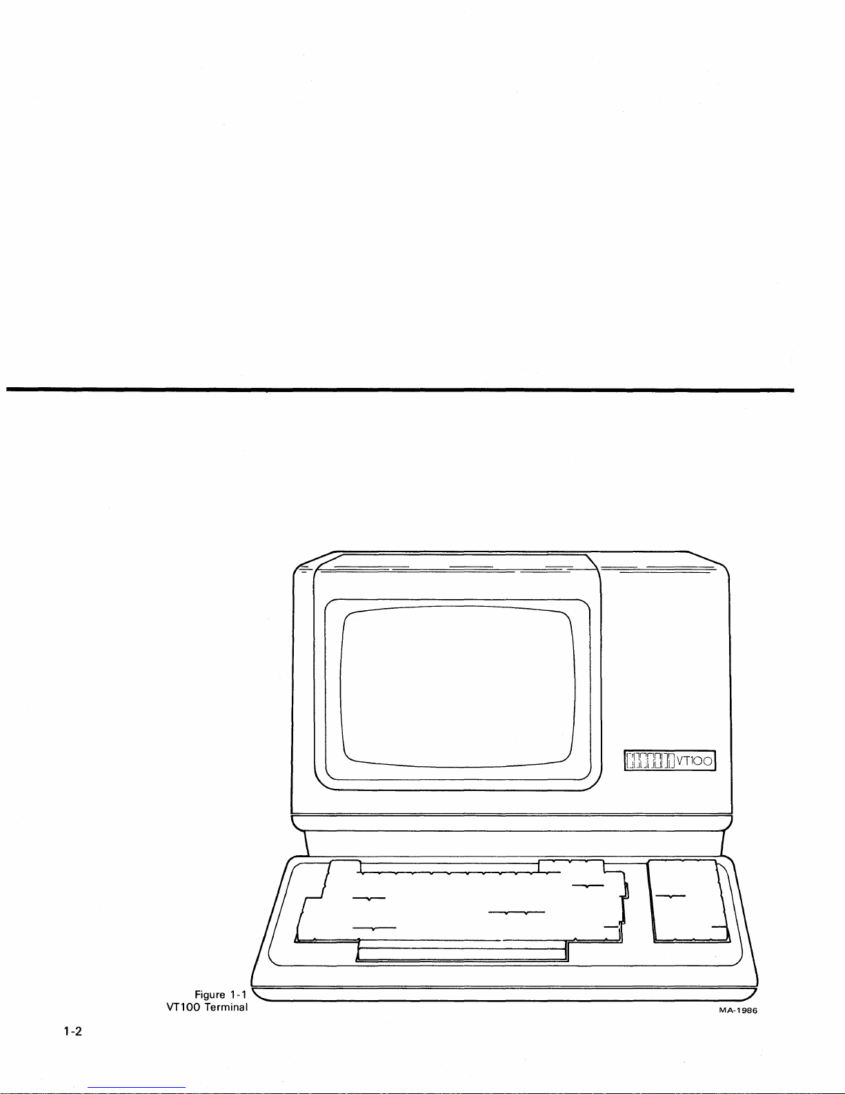
1-2
MA-1986
Page 14
The
VT100
typewriter
computer.
CHAPTER
OPERATOR
is
a simple device
that
uses a video screen instead
If
you can operate a typewriter, you can operate a VT100.
to
operate. The terminal (Figure 1-1)
of
paper and communicates
INFORMATION
is
basically a
with
1
a
Chapter 1
is
divided
1.
Controls and Indicators
2. Setup Mode
3. Definition
Self- Testing the
4.
5.
What
Part 1 shows all the controls and indicators on the terminal and summarizes
the function
Part 2 defines the
Part 3 describes each feature in
further information on a feature mentioned in the
in Part 2.
Part 4 provides information on
required
the
tests have been
Part 5 provides a procedure
with
the VT100. Easily recognized failures
provided
into
five parts:
of
Each
Setup Feature
VT100
to
do
in
the Event
of
each, thus providing a quick reference for these functions.
SET-UP mode and briefly summarizes its features.
to
start the built-in self-tests and
ru
n.
for
each symptom. Check this Jist before calling
of
a Problem
detail. Refer
self-testing the VT100. It outlines the steps
to
follow
in case you encounter any problem
to
this section
SET-UP Summary provided
how
to
interpret the results once
with
simple corrective actions are
for
service.
if
you need
1-3
Page 15
OPERATOR
INFORMATION
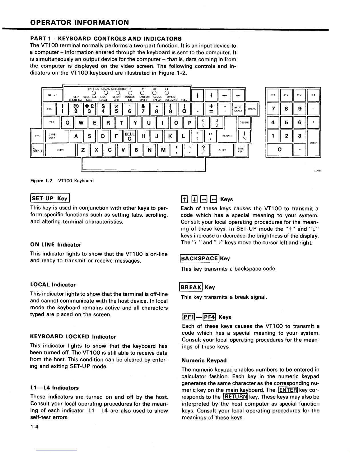
PART
The
a computer - information entered through the keyboard is sent
is simultaneously an
the
dicators on
1 -
KEYBOARD
VT100
computer is displayed on the video screen. The
terminal normally performs a
the
VT100
ET-UP
D
CLEAR
SETI
GDJ[!][XJrnrnGJ[IJwrnrnEJmo
GG000000~G0wwnB
~@000G0~00~~.~Dc:::JgJ
§;]I
'"'''
10000000[J[]ITJG@J
CONTROLS
output
CLEAR
TAB
device for the computer -
keyboard are illustrated in Figure 1-2.
ONONE
LOLKBDOCKED
ALL
LlNEI
TABS
LOCAL
AND
two-part
0 0 0 0
SETUP
TOGGLE
AlB
110
INDICATORS
function.
TRANSMIT
RECEIVE
SPEED SPEED COLUMNS
It
is
an
input
to
the computer.
that
is, data coming in from
following
801132
controls and in-
~~BB
T'
RESET
device to
It
--
[JF1
[JF2
~
~~;~E
EJ
000[J
[JF3 [JF4
0000
~000
0DD
I I
Figure 1-2 VT100 Keyboard
(SET-UP
This key is used
form specific functions such
and altering terminal characteristics.
ON
This indicator lights
and ready
LINE
Key I
in
Indicator
to
transmit
conjunction
as
to
show
that
or
receive messages.
with
other keys to per-
setting tabs, scrolling,
the VT100 is on-line
[!]
[II
B B Keys
Each
of
these keys causes the
code
which
Consult your local operating
ing
of
keys increase
The ''+-'' and
IBACKSPACE
This key transmits a backspace code.
has a special meaning
these keys. In SET-UP mode the
or
decrease the brightness
"-+"
keys move the cursor left and right.
IKey
VT100
proceduresfor
to
transmit
to
your system.
the mean-
"i"
and
of
the display.
a
",t."
LOCAL
This indicator lights
and cannot communicate
mode the keyboard remains active and all characters
typed are
KEYBOARD
This indicator lights
been turned off. The
from the host. This condition can be
ing and exiting SET-U P mode.
L
1-L4
These indicators are turned on and
Consult
ing
self-test errors.
1-4
Indicator
placed on
LOCKED
Indicators
your
local operating procedures for the mean-
of
each indicator. L
to
show
the
Indicator
to
VT100
1-L4
that
the terminal is off-line
with
the host device. In local
screen.
show
that
is still able
are also used
the
keyboard has
to
receive data
cleared by enter-
off
by
the
host.
to
show
IBREAKI
This key transmits a break signal.
IPF11-lpF41
Each
code
Consult
ings
Numeric
The numeric keypad enables numbers to be entered in
calculator fashion. Each key in the numeric keypad
generates the same character as the corresponding
meric key on the main keyboard. The I
responds
interpreted by
keys.
meanings
Key
Keys
of
these keys causes the
which
of
Consult your local operating procedures for
has a special meaning
your
local operating procedures for the mean-
these keys.
Keypad
to
the I RETURNI key. These keys may also be
the
host
computer
of
these keys.
VT100
to
to
your system.
ENTERI
as
special function
transmit
key cor-
a
nu-
the
Page 16
I DELETEI
This key causes the
ter
code
or
may not be erased from the screen.
IRETURNI
This transmits either a carriage return
carriage return
SET-UP
I
LIN
This key transmits a linefeed code.
Key
to
the host system. The deleted character may
Key
(CR) and linefeed (LF) code. This
selectable feature.
EFEEDI
Key
VT100
to
transmit
a delete charac-
(CR)
code
or
is
SET-UP
When the terminal is in
switches the
from SET-UP B
a
LIN
a
In SET-UP mode this key switches the
municate
VT100
CAL).
Al8
E/LOCAL
with
from
~
Key
terminal from SET-UP A
to
SET-UP
~
Key
your system (ON
communicating
SET
-U P mode
A.
with
this
to
SET-UP B
VT100
LI
N
E)
your system (LO-
to
or
stops the
com-
key
or
ISHIFTI
When pressed, this key enables the uppercase function
of
tion
RESET~
When the terminal is in SET-UP mode this key starts
the reset sequence. This has the same
the
80/132
When the
switches
ters per
RECEIVE SPEED Q
When the terminal is in SET-UP B mode
the
ascending order.
Key
all keys.
the SHIFT key
terminal
terminal through
If
a key does
Key
power
COLUMNSr;]
terminal
the
display line size from
line
or
from
not
have an uppercase func-
will
be
disregarded.
result as turning
off
and then on.
Key
is
in SET-UP A mode this key
80
to
132
132
to
80
characters per line.
Key
this
the
receive baud rate settings in
charac-
key steps
CLEAR
In
the
SET/CLEAR
In
tal tabs.
ICAPSI
LOCK
This key enables
betic characters only. All numeric and special symbol
keys remain in lowercase.
I~~ROLLI
When
data from the
second time, transmission resumes from where
stopped. Check your local operating procedures
sure
ALL
TABS
SET
-U P A
VT100.
SET-UP A this key sets
Key
Key
first pressed, this key stops the transmission
that
your system recognizes
l!J
Key
this
key clears all horizontal tabs set in
TA8
~
Key
or
clears individual horizon-
the
transmission
computer
to
the VT100.
of
uppercase alpha-
When
this
key.
of
pressed a
it
was
to
en-
I#£l
TRANSMIT
When
the
terminal through the
ascending order.
TOGGLE
When
the
selected operational feature on or off.
When pressed in combination
key causes a bell code
SPEED
the terminal is in
1/0
the terminal is in SET-UP B mode
Key
~
~
Key
Key
SET
-U P B mode
transmit
to
be sent
baud rate settings in
with
to
this
key steps
this
key
the CTRL key
the
host.
turns
this
ICTRLI
When
causes the
cial meaning
ITABI
This key transmits a
I
Esci
This key transmits a code
meaning
your
mand.
Key
pressed in combination
VT100
Key
Key
to
system
to
transmit
to
your
system.
tab
your system. In
to
treat
the
with
another key, CTRL
a code
code.
which
many
next keys pressed as a
which
has a spe-
normally has a special
applications,
it
tells
com-
1-5
Page 17
OPERATOR
INFORMATION
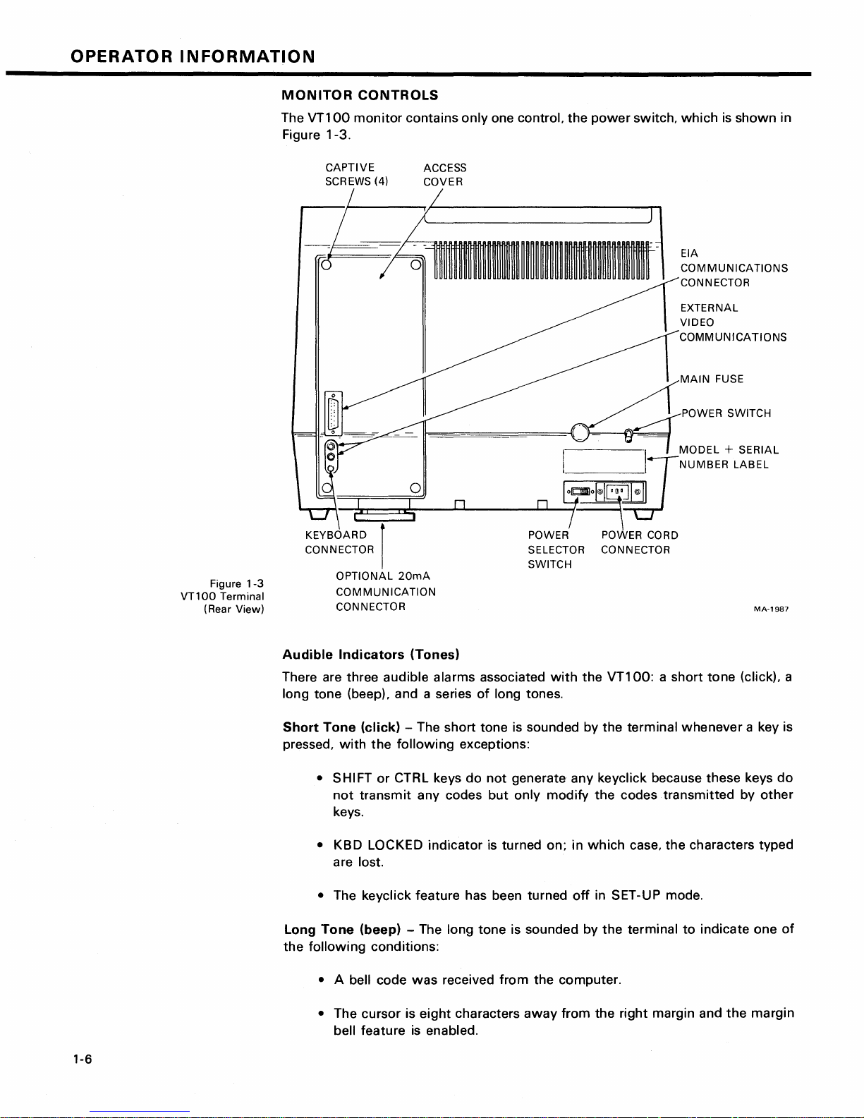
MONITOR
The
VT100
Figure 1-3.
CAPTIVE
SCREWS (4)
l
d
-r-r,
__
CONTROLS
monitor
contains
ACCESS
COVER
only
one control. the
~~~~~~~~~---
~===n~
__
~~
______
power
I
I
~
__
~o~ol@I~~
switch,
~/NUMBER
which
EIA
COMMUNICATIONS
CONNECTOR
EXTERNAL
VIDEO
COMMUNICATIONS
MAIN
POWER SWITCH
"\
MODEL
is
shown
FUSE
+ SERIAL
LABEL
in
VT1
00
(Rear View)
Figure
Terminal
KEYBOARD I POWER POWER CORD
CONNECTOR
1-3
Audible
There are three audible alarms associated
long tone (beep), and a series
Short
pressed,
Long
the
OPTIONAL
COMMUNICATION
CONNECTOR
Indicators
Tone
with
• SHIFT
not
keys.
• KBD LOCKED indicator
are lost.
• The keycJick feature has been turned
Tone
following
20mA
(Tones)
(click)
transmit
(beep) - The long tone is sounded by
- The short tone
the
following
or
CTRL keys
any codes
conditions:
exceptions:
do
SELECTOR CONNECTOR
SWITCH
with
the
VT100:
of
long tones.
is
sounded by the terminal whenever a key is
not
generate any keycJick because these keys
but
only modify
is
turned on; in
the
which
off
in SET-UP mode.
the
a short tone (click), a
codes transmitted by
case, the characters typed
terminal
to
MA-1987
other
indicate one
do
of
1-6
• A bell code
• The cursor is
bell feature
was
eight
is
enabled.
received
characters
from
the computer.
away
from the right margin and
the
margin
Page 18
Series
rapid succession
reading
of
or
Long
writing
Tones
to
indicate
the
- The terminal
SET-UP features. (When this occurs, check
features and then perform the
will
sound the long tone several
that
the nonvolatile memory (NVR) had
Recall or Save operation again.)
times
difficulty
the
SET-UP
in
in
SET-UP
PART
MODE
2
Unlike
turn
memory
switch
The
mode
of
then change the features and store any
most
terminals,
the built-in terminal features on or off. Instead,
(NVR)
which
the
VT100
does
always remembers
not
use switches
what
features have been selected, as
the
or
VT100
had been set.
selection and storage
of
operation called SET-UP mode. When you enter SET-UP mode,
the features stored in the temporary memory
of
built-in terminal features
new
feature selections either temporarily,
is
shown
is
jumpers
to
individually
uses a nonvolatile
performed in a special
the
on the screen. You can
by leaving SET-UP mode; or on a fixed basis, by performing a Save operation. In
either case,
operation
OFF, all temporary feature settings are replaced by the features
the
terminal operation
is
performed, or the terminal is
will
reflect
reset
the
new
feature selection. If a recall
or the terminal power is turned
that
have been
stored on a fixed basis.
SET-UP
When entered, SET-UP mode provides
status. The first presentation - SET-UP A set in the
line. The second presentation - SET-UP B - summarizes the status
Features
at a Glance
terminal and a visual ruler
two
brief summaries
of
the current feature
displays the location
which
numbers each character position on
of
the
of
terminal features.
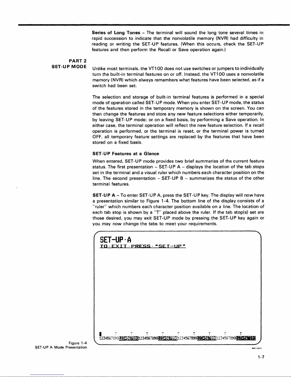
SET -U P A - To enter
a presentation
"ruler"
which
similar
numbers each character position available on a line. The location
each tab stop is
shown
SET
-U P A, press the
to
Figure 1-4. The
by a
"T"
SET
bottom
placed above
-U P key. The display
line
of
the
the
ruler. If the tab stop(s) set are
will
display consists
now
those desired, you may exit SET-UP mode by pressing the SET-UP key again
you may
now
change
the
tabs
to
meet
your
requirements.
tab
the
if
a
status
stops
the
other
have
of
a
of
or
Figure
SET-UP A
Mode
Presentation
1-4
SET-UP·A
TO-EXIT-PREss--SET-UP-
MR·1517
1-7
Page 19
OPERATOR
INFORMATION
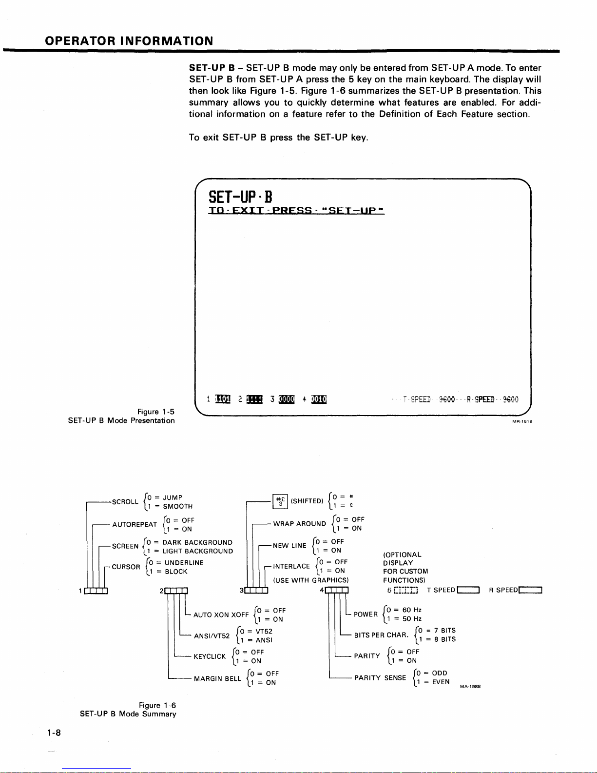
SET-UP B - SET-UP B mode may only be entered from SET-UP A mode. To enter
SET-UP B from SET-UP A press the 5 key on the main keyboard. The
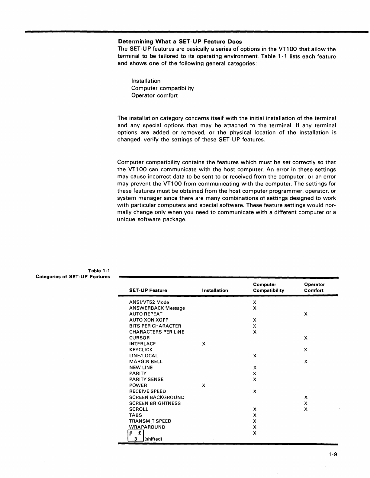
then look like Figure 1-5. Figure
summary
tional information on a feature refer
To exit SET-UP B press the SET-UP key.
allows you
to
quickly determine
SET-Up·B
TO-EXIT-PRESS-"SET-Up·
display
1-6
summarizes the SET-U P B presentation. This
what
features are enabled.
to
the Definition
of
Each
Feature section.
For
will
addi-
Figure
SET-UP B Mode Presentation
SCROLL
AUTOREPEAT
SCREEN
1-5
[0 = JUMP
l1
= SMOOTH
[0
l.1
[0 =
DARK
L 1 = LIGHT BACKGROUND
CURSOR
[0
= UNDERLINE
l.1
= BLOCK
2 3
=
OFF
= ON
BACKGROUND
AUTO XON XOFF
ANSIIVT52
KEYCLICK
MARGIN
[0
L1
BELL
[0 =
l.1
=
= OFF
= ON
[0
l.1
~
(SHIFTED)
~
WRAP
AROUND
NEW LINE
INTERLACE
(USE WITH GRAPHICS)
[0
= OFF
L1
= ON
VT52
ANSI
= OFF
= ON
[0
l.1
[0
l.1
{a
= OFF
= ON
= OFF
= ON
4
= #
1 = £
{a
= OFF
1 = ON
POWER
PER
BITS
PARITY
PARITY
"SPEED'
(OPTIONAL
DISPLAY
FOR CUSTOM
FUNCTIONS)
5
[1:1:1:1
[0 = 60
\..1 = 50
SENSE
CHAR.
[0
= OFF
l.1
= ON
Hz
Hz
[0
l.1
[0 = ODD
l.1
1€OO--'R-SPEED-
T SPEED c:::::J R
= 7 BITS
= 8 BITS
= EVEN
MA-1988
·~oo
MR-1S1a
SPEEDc::::J
Figure
SET-UP B Mode Summary
1-6
1-8
Page 20
Determining
What
a SET -U P
Feature
Does
The SET-U P features are basically a series
terminal
and
to
shows
be
one
tailored
of
the
to
its operating environment. Table 1-1 lists each feature
following
general categories:
I nsta Ilation
Computer
Operator
compatibility
comfort
of
options in the
VT100
that
allow
the
Categories
of
SET-UP
Table 1-1
Features
The installation category concerns
and any special options
options
changed, verify
Computer
the
are added or removed,
the
compatibility
VT100
can communicate
may cause incorrect data
may
prevent
these features
the
must
VT100
that
settings
contains
to
from
be obtained
itself
may be attached
or
of
these SET-UP features.
the
with
the
be sent
to
communicating
from
system manager since there are many
with
particular
mally
unique
SET-UP
change only
software
computers
package.
Feature
when
and special software. These feature settings
you need
to
Installation
with
the
initial installation
to
the
physical location
features
which
host
computer. An error in these settings
or received from
with
the
host
computer
combinations
communicate
of
the
terminal
the
terminal.
must
be set correctly
the
If
any terminal
of
the
installation is
computer;
or
so
an
that
error
the computer. The settings for
programmer, operator, or
of
settings designed
with
a different
Computer
Compatibility
to
would
computer
Operator
Comfort
work
nor-
or a
ANSI/VT52
ANSWERBACK
AUTO REPEAT
AUTO XON XOFF
BITS
CHARACTERS
CURSOR
INTERLACE
KEYCLICK
LINE/LOCAL
MARGIN
NEW
PARITY
PARITY SENSE
POWER
RECEIVE SPEED
SCREEN
SCREEN
SCROLL
TABS
TRANSMIT
WRAPAROUND
E2]
3 (shifted)
Mode
PER
CHARACTER
BELL
LINE
BACKGROUND
BRIGHTNESS X
SPEED
Message
PER
LINE
X
X
X
X
X
X
X
X
X
X
X
X
X
X
X
X
X
X
X
X
X
X
X
1-9
Page 21
OPERATOR
INFORMATION
The operator
comfort
category contains the SET-UP features designed exclusively
for the operator. These features
vidual
preference. These features do
terminal and the computer.
the
The next section, Definition
tion
of
each feature.
How
to
Change a
Changing any
performed by
1.
Enter SET-UP mode by pressing the SET-UP key.
2.
Select the appropriate SET -U P mode by pressing
SET-UP
or
all
of
following
keyboard each
from SET-UP B
of
Feature
the SET-UP features
the same basic steps.
time
to
SET-UP A.
3. Position the cursor above
To
position
TURN"
keys
the
cursor,
may
be used. Some features do
specific key is dedicated
4. Change the feature setting
or
the
keyboard
the
feature
appropriate dedicated key. Each
will
change, generally to the opposite state.
allow
the
operator
not
affect any operations
to
tailor
the
Each SET-UP Feature, describes
is
a simple operation and is generally
the
you
want
to
switch
the
feature
the
"SPACE"
to
changing the feature.
by
pressing either the 6 key on
from SET-UP A
switch
bar,
or
"+-",
tab
"-+",
not
use this step since a
time
VT100
that
the
to
fit
occur between
specific func-
5 key on the main
to
SET-UP B or
stop
to
be changed.
"TAB"
the
and "RE-
the
main
key is pressed
indi-
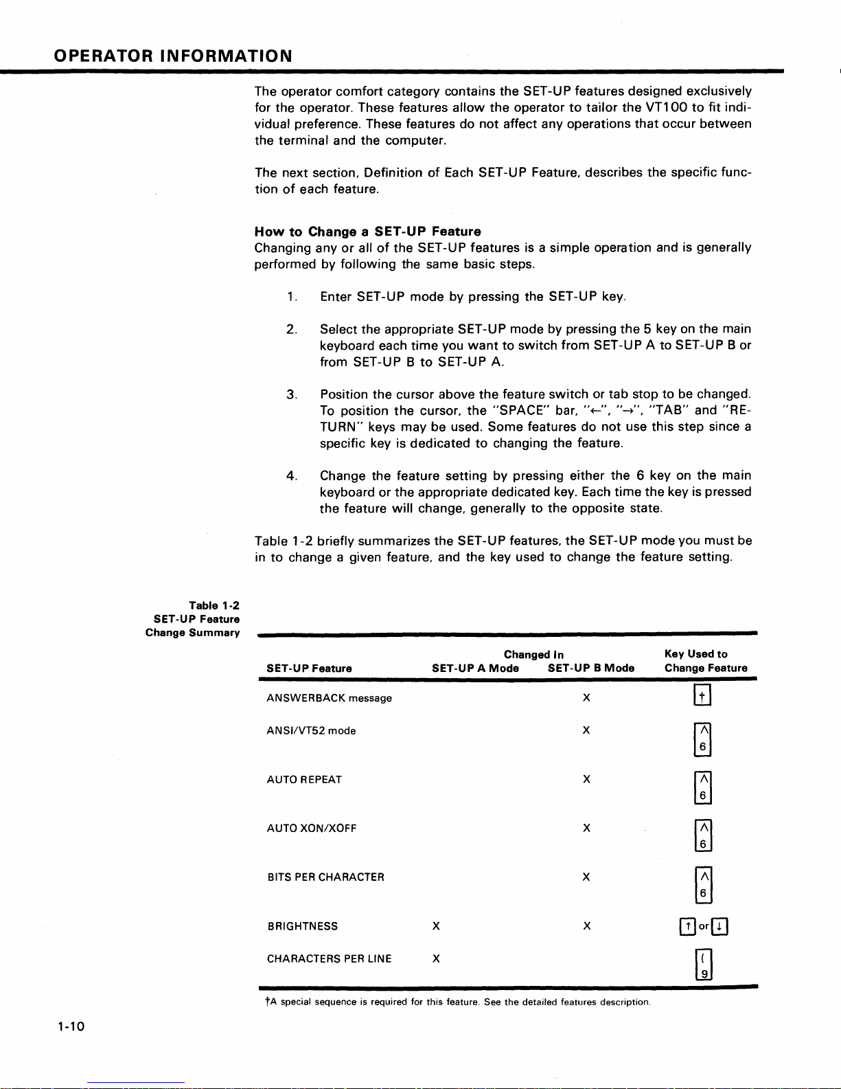
Table
SET-UP Feature
Change
Summary
1-2
Table
1-2
briefly summarizes the SET-UP features,
in
to
change a given feature, and the key used
SET-UP Feature
ANSWERBACK
ANSI/VT52
AUTO REPEAT
AUTO
XON/XOFF
BITS
PER
BRIGHTNESS x
message x
mode
CHARACTER x
SET-UP A
Changed
Mode
the
SET-UP mode you must be
to
change
In
SET-UP B
the
feature setting.
Mode
x
x
x
x
Key Used
Change Feature
to
CHARACTERS
tA
special sequence is required for
1-10
PER
LINE x
this
feature. See
the
detailed features description.
Page 22
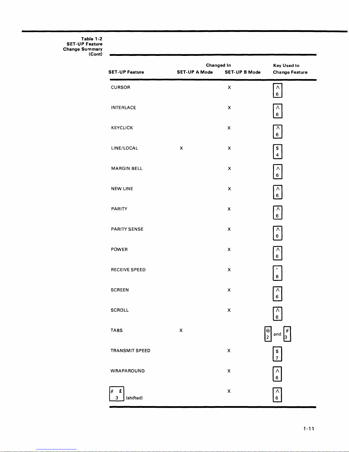
SET-UP
Change
Table
1-2
Feature
Summary
(Cont)
SET-UP
Feature
CURSOR
INTERLACE
KEYCLICK
LINE/LOCAL
MARGIN
NEW
PARITY
PARITY SENSE
BELL
LINE
Changed
SET-UP A Mode
X X
In
SET-UP B Mode
X
X
X
X
X
X
X
Key
Used
to
Change Feature
~
~
~
[TI
[J
~
~
[]
POWER
RECEIVE SPEED
SCREEN
SCROLL
TABS
TRANSMIT
WRAPAROUND
3 (shifted)
EJ
SPEED X
X
~
X
GJ
X
~
X
~
X
~and~
m
X
m
X
[]
1-11
Page 23
OPERATOR
INFORMATION
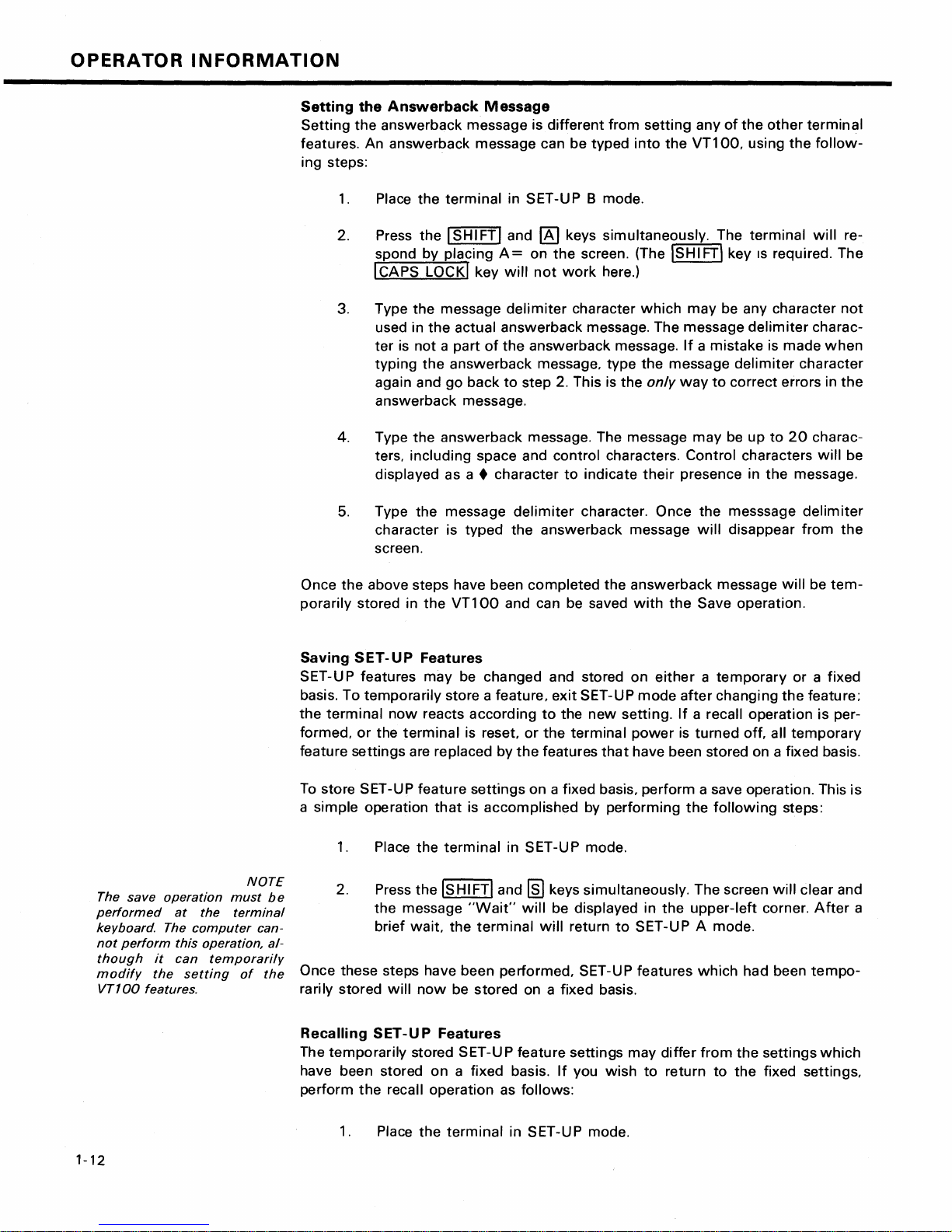
Setting
Setting
the
Answerback
the
answerback message is
Message
different
from
features. An answerback message can be typed
ing steps:
1.
Place
the
terminal
2. Press the I SHI FTI and
spond by placing
I CAPS LOCKI key
3. Type the message
used in
ter
typing
again and
is
the
actual
not
a part
the
answerback
go
in SET-UP B mode.
[!]
A=
on
the
will
not
delimiter
answerback
of
the
answerback message.
message. type the message
back
to
step 2. This is the
keys simultaneously. The
screen. (The ISHI FT' key IS required. The
work
here.)
character
message. The message
answerback message.
4. Type
the
answerback
message. The message
ters. including space and control characters. Control characters
displayed as a • character
5.
Type the message
character is
typed
delimiter
the
to
indicate
character. Once the messsage
answerback
screen.
setting
into
the
which
only
way
their
presence in
message
any
of
the
other
VT100.
using
terminal
may
be any character
delimiter
If
a mistake is made
delimiter
to
correct errors in
may
be up
to
the
will
disappear
terminal
the
follow-
will
charac-
when
character
20
charac-
will
message.
delimiter
from
re-
not
the
be
the
The save
performed
keyboard. The
not
though
modify
VT100
perform
it
the
features.
operation
at
this operation, al-
can
the
computer
temporarily
setting
NOTE
must
be
terminal
can-
of
the
Once
the
above steps have been
porarily stored in
Saving
SET-UP
SET-UP features
basis. To
the
formed.
temporarily
terminal
or
the
Features
now
terminal
the
VT100
may
be changed and stored on
store a feature.
reacts
according
is reset.
feature settings are replaced
To
store SET-UP
a simple operation
1.
2. Press
feature
that
Place
the
terminal
the
ISHIFTI and
the message
brief
wait.
the
settings
is
"Wait"
terminal
completed
and can be saved
exit
to
the
or
the
terminal
by
the
features
on a fixed basis.
accomplished
in SET-UP mode.
rm
keys simultaneously. The screen
will
be displayed in
will
return
the
answerback
with
either a temporary
SET-UP
new
mode
setting.
power
that
have been stored on a fixed basis.
perform
by performing
the
to
SET-UP A mode.
the
after
If
is
Once these steps have been performed. SET-UP features
rarily stored
Recalling
The
temporarily
have been stored
perform
will
now
be
stored
SET -U P
Features
stored SET-U P feature settings may
on
a fixed basis.
the
recall operation as follows:
on a fixed basis.
If
you
wish
to
differ
return
message
will
be
tem-
Save operation.
or a fixed
changing
the
feature;
a recall operation is per-
turned
off. all
temporary
a save operation. This
the
following
upper-left
which
from
to
the
steps:
will
clear and
corner.
had been
the
settings
fixed settings.
After
tempo-
which
is
a
1-12
1.
Place the
terminal
in SET-UP mode.
Page 24
When a
performed
screen are destroyed.
recall
the
operation
contents
NOTE
is
of
the
2.
Press
the
After a brief
the
ISHIFTland
message
"Wait"
wait
the
[B]
keys simultaneously. The screen
will
appear in
terminal
will
the
upper-left
return
to
SET-UP A mode.
corner
will
of
the
clear and
screen.
When a
formed
screen are destroyed.
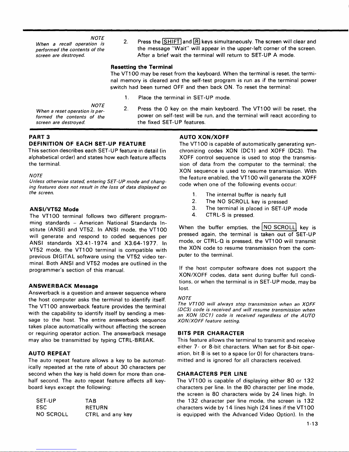
PART
DEFINITION
reset
operation
the
contents
3
OF EACH
NOTE
is
per-
of
the
SET-UP
Resetting
The
nal
memory
switch
FEATURE
the
VT100
may
had been
1.
Place
2. Press
power
the
Terminal
be reset
is cleared and the self-test
turned
the
the
on self-test
fixed SET-UP features.
This section describes each SET -U P feature in detail (in
alphabetical order) and states
the
terminal.
NOTE
Unless
ing
the screen.
will
ANSI
VT52
previous
programmer's
ANSWERBACK
Answerback
the
The
with
sage
takes place
or
may
AUTO
otherwise
features does
ANSI/VT52
The
VT100
ming
standards -
stitute
(ANSI) and VT52. In
stated,
not
Mode
terminal
generate and respond
standards
mode,
the
DIGITAL
minal. Both
ANSI
section
is a
question
host
computer
VT100
answerback feature provides
the capability
to
the
host. The entire answerback sequence
automatically
requiring
also be
operator
transmitted
REPEAT
entering
result
follows
American
X3.41-1974
VT100
software
and
VT52
of
Message
asks
to
identify
action. The
The auto repeat feature
ically repeated
second
half
when
second. The auto repeat feature
board keys
SET-UP
ESC
NO SCROLL
at
the
except
the
key
the
rate
is
following:
TAB
RETURN
CTRL and
how
in the loss
ANSI
to
terminal
using the
modes are
this
manual.
and
answer
the
terminal
itself
without
by
typing
allows
of
about
held
down
each feature
SET-UP
of
two
different
National
mode, the
mode
data
Standards
affects
and
chang-
displayed
program-
VT100
coded sequences per
and
X3.64-1977.
is
compatible
VT52
outlined
sequence
to
identify
the
with
video
in
where
itself.
terminal
by sending a mes-
affecting
answerback
the
mesage
screen
CTRL-BREAK.
a key
to
be
automat-
30
characters per
for
more
than
one-
any
affects
key
all key-
on
In-
ter-
the
from
the keyboard.
When
program
OFF and
terminal
0 key on
AUTO
The
chronizing codes
then
back ON. To reset
in SET-UP mode.
the
main keyboard. The
will
be run, and
XON/XOFF
VT100
is capable
the
XON (DC1) and XOFF (DC3). The
XOFF control sequence is used
sion
of
data
from
the
XON sequence is used
the feature enabled,
code
when
one
1.
The internal
of
the
the
2. The NO SCROLL key is pressed
When
pressed again,
mode,
In
the
puter
If
the
3. The
4.
the
or
XO
N code
to
host
terminal
CTR
L-S is pressed.
buffer
empties,
the
terminal
CTRL-Q is pressed, the
to
resu me transmission
the
terminal.
computer
XON/XOFF codes, data sent during
tions,
or
when
the
terminal
lost.
NOTE
The
VTT
00
will
(DC3) code is
an
XON
XON/XOFF
(DC1) code is received regardless
BITS PER
This feature
either 7 - or
ation,
bit
mitted
and is ignored for a
CHARACTERS
The
VT100
characters
the screen is
the
132
characters
is equipped
always
received
feature
setting.
CHARACTER
allows
8 is set
8-bit
the
characters.
to
PER LINE
is capable
per
line.
In
80
characters
character
wide
with
by
per
14
the
and
a space (or
Advanced
the
terminal
is run as
VT100
terminal
of
automatically
computer
to
resume transmission.
VT100
following
buffer
is reset,
if
the
the
terminal:
will
will
react according
to
stop
to
the
will
generate the XOFF
events occur:
is nearly full
is placed in SET-UP
the
I NO SCRO LLl key
is taken
VT100
software
does
buffer
is in SET-UP mode,
stop
transmission
will
resume transmission
terminal
of
the
line mode,
lines high
to
transmit
When
set
0)
for
characters trans-
II
characters received.
displaying either
80
character per line mode,
wide
by
24
the
(24
lines
Video Option). In
the
termi-
terminal
power
be reset,
generating syn-
the
transmis-
terminal;
With
mode
out
of
SET -U P
will
transmit
from
the
com-
not
support
full condi-
may
when
an
XOFF
of
when
the A UTa
and receive
for
8-bit
oper-
80
or
132
lines high. In
screen is
if
the
132
VT100
the
1-13
the
to
the
is
the
be
Page 25
OPERATOR
132
character
physically
line
NOTE
When
vice-versa, the
mode
changing
the
but
current
INFORMATION
per
line
same
width
the
characters are
from
80
to
contents
mode,
as in
132
the
character
of
displayed lines
the
80
character
more
compact.
per
line
the screen are lost.
mode
are
per
or
When
key
generates
terminal
NOTE
If
double
since
the
the
new
only
to
perform a line
line
feeds
computer
line
occur
is
feature
the
CR
consistently,
already
is disabled,
code;
an
feed only.
performing
the
LF
code causes
turn
this
this
function.
RETURN
feature
the
off
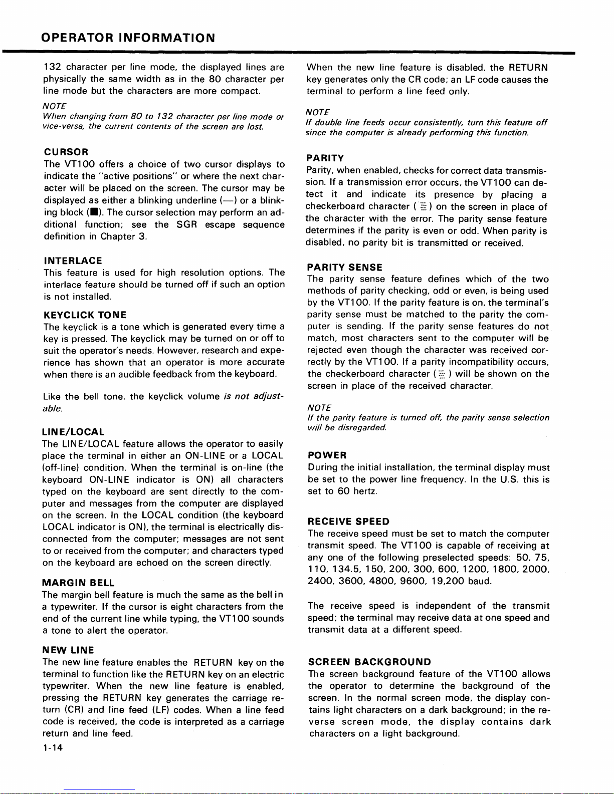
CURSOR
The
VT100
indicate
acter
displayed
ing
block
ditional
definition
the
will
(.).
function;
offers a
"active
be
placed
as
either a blinking
The
in
Chapter
INTERLACE
This
feature
is used
interlace feature
is
not
installed.
KEYCLICK
The
keyclick
TONE
is a
key is pressed. The
suit
the
operator's
rience has
when
Like
there
the
shown
is an
bell tone,
able.
LINE/LOCAL
The
LINE/LOCAL
the
place
(off-line)
keyboard
typed
puter
on
the
LOCAL
connected
to
or
on
the
MARGIN
The
a
typewriter.
end
a
tone
terminal
condition.
ON-LINE
on
the
keyboard are
and messages
screen. In
indicator
from
received
from
keyboard are
BELL
margin
of
bell
the
current
to a lert
If
the
the
the
feature
choice
positions"
on
cursor
see
3.
for
should
tone
which
keyclick
needs.
that
audible
the
feature
in
either
When
indicator
from
the
LOCAL
is ON),
computer;
the
echoed
cursor
line
while
operator.
of
or
the
screen. The
underline
selection
the
SGR escape sequence
high
resolution options. The
be
turned
is
generated
may
However,
an
operator
feedback
keyclick
allows
an
the
terminal
is ON) all
sent
the
computer
condition
the
terminal
computer;
on
is
much
is
eight
typing,
two
cursor
where
displays
the
cursor
(-)
may
perform
off
if
such an
every
be
turned
on
research and
is
more
from
the
keyboard.
volume
the
ON-LINE
directly
is
not
operator
or a LOCAL
is
on-line
to
are
(the keyboard
is
electrically
messages are
and characters
the
the
screen
same
directly.
as
characters
the
VT100
to
next
char-
may
be
or a blink-
an
ad-
option
time
or
off
to
expe-
accurate
adjust-
to
easily
(the
characters
the
com-
displayed
dis-
not
sent
typed
the
bell
in
from
the
sounds
PARITY
Parity,
sion.
tect
checkerboard
the
determines
disabled,
a
when
enabled,
If a transmission
it
and
character
if
the
no
parity
PARITY
the
methods
by
parity
puter
match,
parity
the
VT100.
sense
is sending.
most
SENSE
sense feature
of
parity
must
characters
rejected even
rectly
by
the
VT100.
the
checkerboard
screen in place
checks
error
indicate
character
with
the
parity
bit
its
(::::::
error. The
is even
is
transmitted
checking,
If
the
parity
be
matched
If
the
parity
sent
though
the
If a parity
character ( :::::: ) will
of
the
received character.
for
occurs,
presence
) on
defines
odd
feature
character
NOTE
If
the
parity
will
be
disregarded.
feature
is
turned
off, the
POWER
During
be
set
set
to
the
to
60
initial
the
hertz.
installation,
power
line
frequency. In
the
RECEIVE SPEED
The receive speed
transmit
anyone
speed. The
of
the
110,134.5,150,200,300,600,1200,1800,2000,
2400,
3600,
The receive speed is
speed;
transmit
the
data
terminal
must
be
VT100
following
4800,
9600,
independent
may
at a different
set
is capable
preselected
19,200
receive
speed.
correct
the
data
VT100
by
the
screen in place
parity
sense
or
odd.
When
or
received.
which
or
even, is
is on,
the
to
the
parity
sense features
to
the
computer
was
received
incompatibility
be
shown
parity
sense
terminal
the
to
match
the
of
speeds:
baud.
of
the
data
at
one
transmis-
can
placing
feature
parity
of
the
being
terminal's
the
do
will
occurs,
on
selection
display
U.S.
this
computer
receiving
50,
transmit
speed
de-
a
of
is
two
used
com-
not
be
cor-
the
must
is
at
75,
and
NEW
LINE
The
new
line
feature
terminal
typewriter.
pressing
turn
(CR)
to
function
When
the
and
RETURN
code is received,
enables
like
the
the
new
key
line
feed (LF) codes.
the
code
the
RETURN key
RETURN key on an
line
feature
generates
is
interpreted
return and line feed.
1-14
the
When
on
electric
is enabled,
carriage re-
a line feed
as a
carriage
the
SCREEN
The screen
the
operator
screen. In
tains
light
verse
characters
screen
BACKGROUND
background
to
determine
the
normal
characters
mode,
on a light
feature
screen
on a dark
the
background.
of
the
the
background
mode,
the
background;
display
VT100
display
in
contains
allows
of
the
con-
the
re-
dark
Page 26
SCREEN
Unlike
tain
stead, the
brightness. This feature
of
mechanical controls and still
select
comfort
may
BRIGHTNESS
most
video terminals,
switches
the
or
knobs
VT100
desired level
under
varied
electronically
be saved like any
to
eliminates
of
lighting
other
SCROLL
Scrolling is
isting lines on the screen
the
bottom
two
ways:
mode,
computer
the
or
jump
new
lines appear
sends
upward
top
of
scroll
them
the
or
to
screen.
or
smooth
on
to
baud rates, the data is very
rapid
upward
mode, a
of
data
ment
of
the
data
NOTE
Smooth
per
second
feature
puter
to ensure
mode
is enabled.
must
movement
limit
is placed on
may
be sent
lines occurs
to
be read as
scroll
mode
to
be
added
be
enabled
that
of
the
to
the
at a smooth
it
appears on
allows a maximum
to
the
and
data
is
TABS
Just
like a
typewriter,
preselected
points
individually changed,
the
on a line. These
or
totally
the
VT100
adjust
screen brightness. In-
does
controls
the
high failure rate
allows
the
brightness for
conditions. This
feature in
downward
make
It
the
movement
room
for
new
can be performed in
scroll. In
the
screen as fast as
the terminal.
difficult
the
lines. In
speed
terminal. The
At
to
read due
at
which
upward
smooth
steady rate
the
screen.
of
when
can
tab
six lines
Auto
by
the
smooth
jump
stops
screen. The
supported
not
lost
VT100
cleared and then reset.
not
con-
the screen
operator
to
maximum
setting
terminal.
of
ex-
lines
at
jump
scroll
the
the
higher
to
the
scroll
new
lines
move-
allowing
of
data
XON/XOFF
host
com-
scroll
or
tab
to
may
be
TRANSMIT
Transmit
receive speed. The
anyone
speed
of
the
SPEED
must
VT100
following
be set
to
is capable
preselected
match
of
transmit
the
computer
transmitting
speeds:
50,75,110,134.5,150,200,300,600,1200,1800,
2000, 2400,
Transmit
terminal
data at a
3600,
speed is
may
transmit
different
4800,
9600,
independent
data
at
speed.
and
19,200
of
receive speed;
baud.
the
one speed and receive
WRAPAROUND
When
this
feature is enabled,
the
81
st
or
133rd
character (depending upon the line size selected) inserted
on a line is
position
not
enabled, the
lowing
character position
automatically
of
the next line.
characters
81
st
would
of
or
the
placed in
If
the
wraparound
133rd
be
overwritten
current
the
first
character
feature
was
character and all fol-
into
the
last
line.
ri£l
L.!J (shifted)
The
VT100
United
acter sets is one character,
the standard U.S. character
percase 3 key on
character. The £ character is displayed
character set is selected.
contains character sets for
Kingdom. The difference
the # or
set
the
main keyboard displays the #
the
between
£ symbol.
is selected,
U.S. and
the
when
two
the
the
the
char-
When
up-
U.
K.
at
PART
4
SELF-TESTING
THE
VT100
A
self-test
the condition
checks the
mode
is
of
the
following
built
Advanced Video M
Nonvolatile
Internal
Memory
memory
Keyboard
This
test
is performed
Self-Test Error Codes
There are
Fatal errors cause
information
random
characters)
LEOs, L
guaranteed
two
broad categories
is displayed on
pattern
1-L4;
of
is
a possible error code displayed on
however,
if
a fatal
the
characters. The
into
the
terminal
should a
items:
emory
(NVR)
automatically
terminal
the
screen; however,
no
terminal
error
is found.
VT100
(if
of
to
that
automatically,
fault
be suspected. The
option
is installed)
whenever
the
terminal
errors: fatal and nonfatal.
immediately
stop all operations. No
the
only
error indication (in
function,
including
or
is
screen
most
addition
the
programmable
the
on
command,
self-test
turned
likely
to
lighting
tests
program
on.
intelligible
contains
the random
keyboard
of
LEOs, is
1-15
a
Page 27

OPERATOR
INFORMATION
The
loopback
formed
be
invoked
the
proper
See the
for
further
test.
test
on
power-up;
programmer's
information
Nonfatal
is
separately
escape sequence.
Error
NOTE
not
per-
it
must
with
section
on
this
Table
1-3
Displayed
Codes
Nonfatal errors
LOCAL
the
mode
screen.
There are
1.
2.
3. Keyboard missing
do
not
halt
the
terminal
and an error code character is displayed in the
four
types
of
nonfatal errors:
Advanced Video
Nonvolatile
data
Option
RAM
or
malfunction
4. Data loopback error (Data)
Table
1-3
shows
the
possible
nonfatal
screen and the failure represented
Displayed
Character
AVO
Faulty
NVR
Module
KBD
Data
processor. Instead, the
data
RAM
(AVO)
checksum
error (NVR)
(KBD)
error
characters
by
each character.
that
terminal
upper-left
may
appear on
is forced
corner
to
of
the
1
2
3 X
4
5 X X
6
7
8
9 X
X
X
X
X X
X X
X
X
X
X
<
X
>
PART
If
procedure. This
some
If
items
it
appears
other
the
terminal
an
5 -
operator
WHAT
that
part
X X
X X X
TO DO
there is a problem in the terminal, you should
test
will
of
the
appears
can check
X
X
X
X
X
X
X
X
X
X
X
IN
THE EVENT OF A
help
to
determine
computer
to
be faulty, refer
prior
system.
to
making
PROBLEM
if
the
problem lies in
to
Table 1-4. This
a service call.
initiate
your
table
the
self-test
terminal
describes
or
in
the
1-16
Page 28
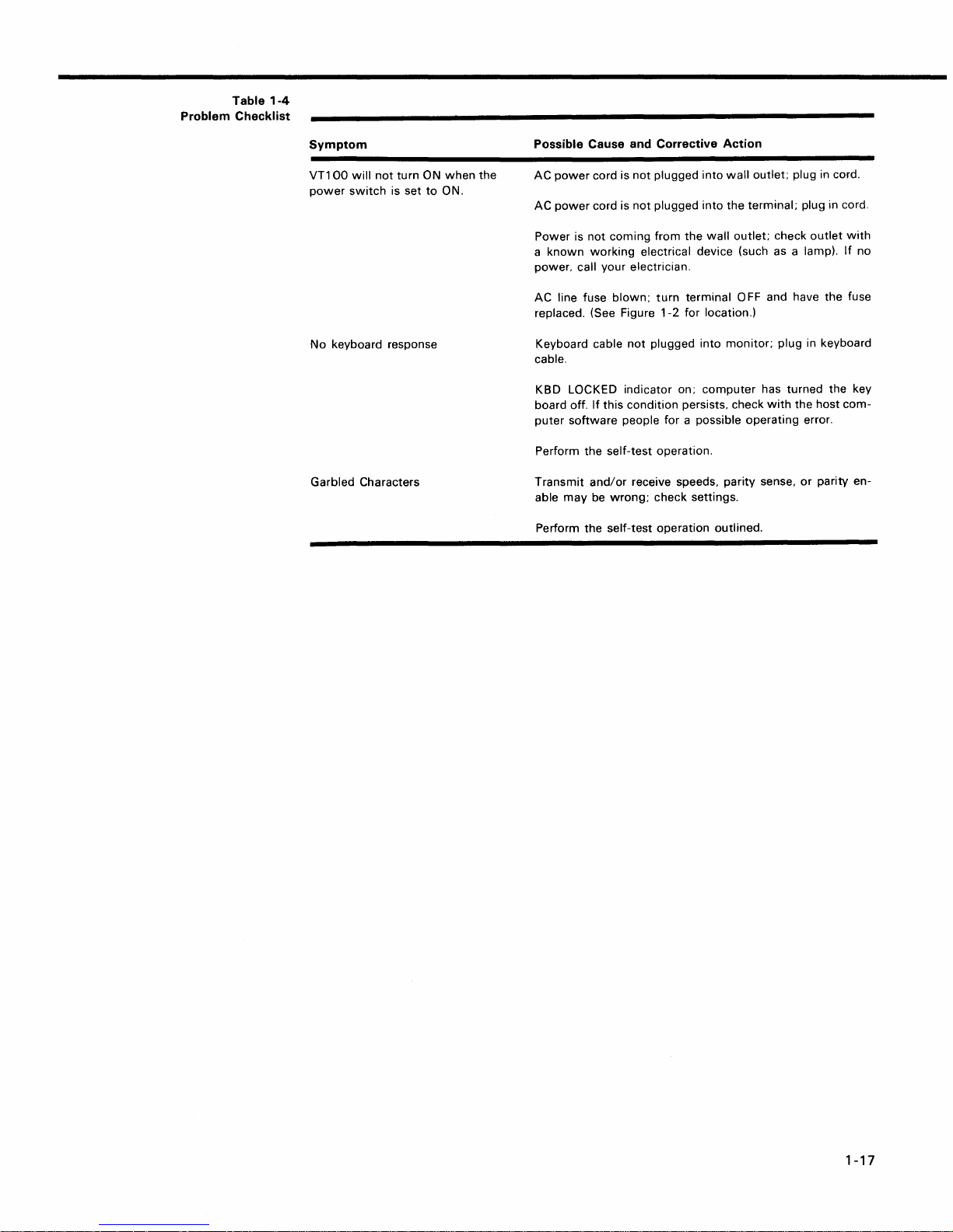
Table
1-4
Problem Checklist
Symptom
VT1
00
will
not
turn ON
power
switch
is set
No
keyboard response
Garbled Characters
to
when
ON.
the
Possible Cause and Corrective Action
AC
power
cord is
not
plugged
AC
power
cord is
not
plugged
Power is
a
power.
AC line fuse
replaced. (See Figure
Keyboard cable
cable.
KBD LOCKED indicator on;
board off.
puter
Perform the self-test operation.
Transmit
able
Perform
not
known
coming from
working
call your electrician.
blown;
If
this condition persists. check
software
and/or
may
be
wrong;
the
self-test operation outlined.
electrical device (such as a lamp).
not
plugged into
people for a possible operating error.
receive speeds. parity sense.
check settings.
the
turn
terminal 0
1-2
for location.)
into
wall
into
the
wall
outlet;
monitor;
computer
terminal;
FF
outlet; plug in cord.
plug in cord.
check
outlet
with
If
and have the fuse
plug in keyboard
has turned the key
with
the host
or
parity en-
com-
no
1-17
Page 29

Page 30

CHAPTER
2
Installation,
Information
Interface
and Specifications
Page 31

Page 32

INFORMATION,
SITE
CONSIDERATIONS
The design
selecting a place
on
ment
to
operate the terminal. Extremes
A summary
section.
of
suitable
the
VT100
to
the terminal operator
of
VT100
terminal (Figure 2-1)
in
which to install the terminal.
guaranteed operating conditions is found
CHAPTER
INSTALLATION,
AND
will
will
be
a satisfactory environment
of
temperature and humidity should be avoided.
SPECIFICATIONS
normally pose
In
most
INTERFACE
few
constraints
cases, any environ-
in
at
the end
2
which
of
this
UNPACKING
The
VT100
VT100
VT100
VT100
VT100
VT100
AND
INSTALLATION
shipping carton contains the following items:
monitor
detached keyboard
power cord
SET-UP label
User's Guide
2-3
Page 33

INSTALLATION,
8.9
CM
. ]
(3 112 IN.)
4.8
(1
7/8
~
__ ~ __ I ___
INTERFACE
flC
CM
IN.)
c:J
L 11.1 CM
20.32
....------------
(4
CM (8 IN.)
INFORMATION,
36.8
(14
~
t:J
-l
3/8
IN.)
CM
112 IN.)
AND
....------36.2
51.4 -CM
SPECIFICATIONS
~-----30.5
(20
1/4
IN.")
CM
CM
(14
-------------'
(12
IN.)-------.t
1/4
IN.)-------.t
2-4
"MEASUREMENT
VT100
Terminal Dimensions
Figure 2-1
/'
'"
~
t
Y.
TAKEN WITH THE KEYBOARD PLACED FLUSH
41.3
45.7CM
CM
(161/4IN.)
(18
IN.)
TO
FRONT OF
J
'f
TERMINAL
UNDER UNDERCUT.
MA-1991
Page 34

To install the
1.
Remove
work
2.
Place
cord
(Figure
VT100
perform the
the
area.
the
keyboard in front
into
the
2-1).
following
VT100
from the shipping carton and place
keyboard receptacle located on
steps:
of
the terminal and plug
the
it
in the desired
the
keyboard coiled
rear
of
the
terminal
3. Verify
voltage
4. Connect
terminal and plug the other end
outlet.
5.
Connect
receptacle.
6.
Turn
the
on
cursor
7.
Set the desired SET-UP features
this
8.
Once the installation setup procedure is complete, record the SET-UP
features
the underside
CAPTIVE
SCREWS (4)
that
(115
the
the
the
power
power-up
the
keyboard
will
manual.
selected on
the
power
V is standard in
power
communications
switch
self
be visible in
of
ACCESS
COVER
selector
cord
to
on. The terminal
test
and
will
be turned on.
the
the
the keyboard.
switch
the
U.S.) and
the
power
cable
either
upper-left corner
VT100
cord receptacle on the rear
of
the
to
the ON LINE
After
outlined
SET-UP label and attach
shows the correct
the
power
power
the
will
cord into a nearby
appropriate
now
automatically
or
approximately one
of
the
in the operator's section
switch
communications
LOCAL
screen
wall
light
minute
the
outlet
is off.
of
the
wall
perform
located
the
of
label
to
vn
00
Figure
Rear
2-2
View
1
6
~~1-~~==~~--~~------~~-~i'~-~-=-=~'
KEYBOARD
CONNECTOR
OPTIONAL
COMMUNICATION
CONNECTOR
~
__
I
20mA
~~~~~mnmmr-
DDD
@
g
POWER POWER CORD
SELECTOR CONNECTOR
SWITCH
EIA
COMMUNICATIONS
CONNECTOR
EXTERNAL
VIDEO
COMMUNICATIONS
MAIN
POWER
-I
MODEL + SERIAL
NUMBER
FUSE
SWITCH
LABEL
MA-1987
2-5
Page 35

INSTALLATION,
INTERFACE
INFORMATION,
AND
SPECIFICATIONS
INTERFACE
INFORMATION
EIA
Interface
USER
The
ventive maintenance by the owner. The
and
The
MAINTENANCE
keyboard keys are the only moving parts
VT100
water
VT100
or any mild detergent. Cleaners
packaging is
not
meant
to
with
be
weatherproof; there are several openings
of
the terminal and require no pre-
surfaces may be cleaned
solvents should
not
with
be used.
in the case through which liquids, coins, paper clips, and other objects can
Such objects
into contact
objects on the
Rubbing
not remove the keycaps to
switch contacts
Keep the ventilation
under the
The basic
terminal interfaces to the
terminal
summarizes the
nal as used in
with
the
keys
VT100
VT100
which
would
disturb
the
electronic operation
the circuitry. For this reason, avoid
top
of
the terminal,
with
a dry
or
using excessive
or
barely moist cloth should suffice
of
the terminal if they came
putting
water
drinks and metal
to
clean the terminal.
to
clean them. Do
clean them more thoroughly; damage may result to the
if
they are replaced incorrectly.
slots clear. Blocking these slots by placing objects on
may
cause the terminal
to
overheat.
operates on full duplex, asynchronous communication lines. The
line
with a 25-pin
meets the requirements
EIA connector signals; the
the
basic VT100.
connector mounted on the back
of
EIA specification RS232-C. Table 2-1
following
paragraphs explain each sig-
top
soap
fall.
of
of
the
or
EIA
Connector
Table
Signals
2-1
Pin
Number
1
2
3
4
5
6
7
8
9
10
11
12
13
14
15
16
17
18
19
20
Description
Protective ground
Transmitted data
Received data
Request to send
Clear
to
send
Data set ready
Signal ground (common return)
Carrier detect
(not used)
(not used)
Same
as
pin
clock
19
to
send) speed select
(Secondary carrier detect) speed indicator
(not used)
(not used)
Transmit
(not used)
Receive clock
(not used)
(Secondary request
Data terminal ready
21
22
23
24
25
2-6
(not used)
Ring indicator
Same
as
(not used)
(not used)
pin
19
Page 36

Protective
This conductor is electrica
chassis. Use
purposes is
Transmitted
VT100
The
break signals on this circuit,
Ground
not
- Pin 1
lIy bonded
of
this conductor for reference potential
to
the VT 1
allowed.
Data
(from
VT100)
- Pin 2
00
transmits serially encoded characters and
which
is
held in the mark
state when neither characters nor break signals are
being transmitted.
Received
VT100
The
VT100)
receives serially encoded characters gener-
- Pin 3
Data
(to
ated by the user's equipment on this circuit.
Request
Asserted at
Clear
Ignored
Data
Ignored
Signal
to
Send
(from
VT100)
- Pin 4
all times when terminal is powered up.
to
Send
(to
at
all times.
Set
Ready
at
all times.
Ground -Pin
VT100)
(to
- Pin 5
VT100)
7
- Pin 6
This conductor establishes the common ground reference potential
permanently connected
for
all voltages on the interface. It
to
the
VT100
chassis.
Carrier
Ignored
Speed
Detect
at
all times.
Select
(to
VT100) -Pin
(from
VT100)
8
- Pins
11,
This signal is alternately called Secondary Request
Send. The basic VT
serted state at
Speed
Indicator
100
all times.
(to
VT100) -Pin
maintains this line in the unas-
12
This signal, alternately called Secondary Carrier Detect, is ignored
Transmission
Ignored
at
Receive
Ignored
Data
at
Terminal
Clock
all times.
Clock
all times.
at
all times.
(to
VT100)
Ready
(to
(from
VT100)
- Pin
VT100)
- Pin
17
- PI N
Data Terminal Ready is asserted at all times.
is
Ring
Indicator
Ignored
at
all ti
(to
meso
VT100)
- Pin
22
19,
15
and
20
23
to
Current
Optional
Loop
20
mA
Interface
Electrical
VT100
unasserted state is
+12.0
VT100
an
or
+2.25
than
and
Characteristics
Output
Voltages -On
V.
Input
Voltages
open circuit
V is interpreted
±25
V are
CCITI
Recommendation V.28.
all signals designated
-6.0 V to
-12.0
- On signals designated
i$
interpreted
as
a space
not
allowed. These levels are compatible
as
or
In most current loop applications, the
figuration -
that
is, current is supplied
and receiver are both passive, both
the
mark state when power is turned off.
Conversion from active
to
passive (or vice versa) requires moving a slide switch.
In active mode either the transmitter
that
the
VT100
present and the transmitter
sources the
will
20
go
mA
to
turned off.
"from
VT100,"
V;
the
space or asserted state is
"to
VT100,"
-25.0 V to
a mark or unasserted state, and
the
mark or
+6.0 V to
+0.75
+25.0 V to
asserted state. Voltages greater in magnitude
with
EIA STD RS232-C
VT100
to
will
be connected
in
the VT100. In this mode,
a passive con-
the
transmitter
optically isolated, and the transmitter goes
or
the
receiver or both may be connected so
of
current. In active mode isolation is
the
space state when
power
to
the
not
VT100
V
to
is
2-7
Page 37

INSTALLATION,
INTERFACE
INFORMATION,
AND
SPECIFICATIONS
Figure
access cover and the individual pin assignment.
Electrical Characteristics
The
Transmitter
Receiver
2-3
shows the
electrical characteristics
Open circuit voltage
Voltage
Spacing current
Marking current
Voltage drop marking
Spacing current
Marking current
drop marking
20
rnA current loop interface connector mounted
of
the
20
rnA current loop interface are shown below:
Min
5.0V
20
rnA
15 rnA
Max
50V
4.0V
2.0mA
50
rnA
V
2.5
3.0
rnA
50mA
to
the
o
o
TERMINAL
ACCESS
COVER
ASSIGNMENTS
PIN
1 - .TEST
2 -
3 5 -
7 - RECEIVE +
8 - PROTECTIVE GROUND
NEGATIVE
TRANSMIT
RECEIVE TRANSMIT
-
+
o
Figure
2-3
20
mA
Current Loop Interface
2-8
00000000
123
20mA
CU
o
LOOP CONNECTOR
5
78
RRENT
MA-1992
Page 38

Video
External
Connections
In
addition
the
transmitter
ohms.
to
the
above specifications for passive operation, active mode
or
receiver in series
with
a source
of
17 V
±5
percent and
will
place
660
In addition
external video devices. The video devices may act either as a slave
when
the
connectors are the
just
lower
Composite
The composite video
combining the video signal
lowing
EVEN
FIELD:
LAST DISPLAYED SCAN
TIME_
ODD FIELD: I
LAST DISPLAYED .SCAN
EVEN
FIELD
1.0 V
14-----------------
OF
OF
14------1---------------
to
the
EIA interface, the
connected
VT100
below
connector,
to
the composite video
video section
two
the
EIA connector. The upper connector,
J9,
Video
Output
when
female BNC connectors located on the back
is
the
video output.
(J9)
output
provides
with
nominal characteristics. (Refer
VERTICAL BLANKING
60
Hz
NON-INT = 2 SCANS
60
Hz
INT = 2 SCANS
50
Hz
NON-INT =
{
50
Hz
INT =
:\r\
I START
:
I
I
: VERTICAL
EVEN
60HZINT
{
50
Hz
OF
FIELD
INT
BLANKING
= 2
=
INTERVAL
25
SCANS
24
SCANS
INTERVAL
112
SCANS
24
112
SCANS
VT100
connected
is also capable
output
to
the video input. The external video
RS 1 70-like
of
or
provide synchronized video
J8,
is the video
output
(see note) generated by
a composite sync signal. The
to
Figure 2-4.)
60
Hz
NON-INT =
60
Hz
INT
50
Hz
NON-INT =
{
50
Hz
INT =
=22
22
75
74
SCANS}
SCANS
SCANS
SCANS
___
.~~~
r--
H
PE
{60
Hz
INT
50
Hz
INT
easily interfacing
to
the
of
the
terminal
input
while
output
~
RIOO
OF
FIRST
SCANS IN
~
6356
has
240
DISPLAYED
EVEN
"' ± 50
VT100
the
the
fol-
FIELD
m
to
to
OV
TIME-
=
BRIGHT
NORMAL = .79
SYNC
FRONT PORCH =
Composite Video
1.00V_§
DIM = .64V-
BLACK = .29 V - u---'f
=O.OOVOLT-
H SYNC = 4.71
V-
1.54/Ls ± 50ns
/LS
± 50
Figure
2-4
Output
!\r\
I START
-1
OF
ODD FIELD
H
BLANK
{11.84/LS ± 50
F 12.3
I I
•
1---------1
4
/Ls ± 50
U U
~I
ns
r-
~Q
ns
180
COLUMN
ns
1132
COLUMN
=
2.33/Ls ± 50ns
H PERIOD = 63.56
-./
j..
/LS ± 50
~
H PERIOD
NOTES:
IN
EVEN
UOUSLY.
USED.
IN
EVEN
FIELD.
ALL
SCANS.
u
-...J
ns
~
6356., ± 50
NON-INTERLACED OPERATION THE
FIELD
IS REPEATED
AND
THE ODD FIELD IS NOT
THE INTERLACED OPERATION THE
FIELD ALTERNATES WITH THE
FIELDS CONTAIN
I '---
~n
j..-v
SYNC =
240
rL
27.28
±
NS
CONTIN-
DISPLAYED
/.lS
200
ns
ODD
2-9
Page 39

INSTALLATION,
NOTE
The use
strict
To agree
put
pacitor
output. Failing
mA
quirement
presents
most
fact
NOTE
The external video source
must
VT100;
erencing
on
put.
of
decoupling is
agreement
with
load
requires a
in
dc
short
monitors
ac-coupled.
be synchronized to the
it
the
the
composite
with
RS170.
RS170
series
circuit
is violated. This
no
may
composite
10
with
to
do
so,
current
problem
which
do this
video
the
INTERFACE
2.
3.
4.
5.
not
in
out-
f..LF
ca-
the
the 2
re-
with
are
in
Video
An
analog signal applied
signal in such a
spond
at
that
by
ref-
sync
out-
1.
2. Black level = 0 V
3.
4. Maximum continuous input
INFORMATION,
1.
Output impedance
Sync level
Black level = approximately
White
The composite sync waveform conforms
vertical interval
pulses, and six more equalizing pulses. The
Equalizing pulse
Vertical pulse
Horizontal pulse
Horizontal blank
Front Porch
Input
(J8)
way
to
the intensity
= 0 V
level = approximately 1.0 V
width
to
that
the beam intensity
of
that
AND
=
is
composed of six equalizing pulses, six vertical sync
width
width
width
the video input
signal which would tend
SPECIFICATIONS
75
ohms, dc-coupled
0.3 V when
with a 75
=
2.33
f..LS
=
27.28
= 4.7 1
=
=
will
f..Ls ± 50
11.84
12.34
1.54
f..LS
be
"ORed"
at
any point on
loaded
with
ohm
to
EIA
RS
170
±50
f..LS
timing
±200
is
ns
ns
ns
f..LS
±50
ns/80
f..LS
±50
ns/132
±50
ns
with
the
to
make the beam brighter
point. This input has the following nominal characteristics.
Input impedance =
White
level = 1.0 V
75
ohms, dc-coupled
=
±2.0
V
75
ohms
load
standards. The
as
follows:
column mode
column mode
the internal video
screen
will
corre-
VT100
SPECIFICATIONS
Dimensions
Weight
Environment
Monitor
Keyboard
Monitor
Keyboard
Shipping
Weight
Operating
Non-Operating
Height:
Width:
Depth:
Height:
Width:
Depth:
Minimum
13.6
2.0
18.6
Temperature:
36.83
45.72
36.20
8.89
cm (3.5 inch)
45.72
20.32
table depth:
kg
(30
Ibs)
kg (4.5 Ibs)
kg
(41
Ibs)
cm (14.5 inch)
cm (18 inch)
cm
(14.25
cm
(18
cm (8 inch)
100 to
Relative humidity: 10%
Maximum
Minimum
Altitude:
Temperature:
Relative humidity: 0
Altitude:
wet
dew
2.4
9.1
Km
-400 to
km
bulb:
280 C (820 F)
point: 20 C
(8,000
to
(30,000
inch)
inch)
51.4
400 C
to
90%
ft)
660 C
95%
ft)
cm
(20.25
(500 to
inch)
1040 F)
(360 F)
(-400 to 1510 F)
Power
Line
Line Frequency
2-10
Voltage
90-128
180-256
V RMS single phase, 2 wire
V RMS single phase, 2
(switch-selectable)
47-63
Hz
wire
Page 40

Display
Keyboard
Current
Input Power
Current
limiting
Power cord
CRT
Format
Character
Character size
Active Display Size
Character Set
Cursor type
General
3.0
A RMS maximum
1.5 A RMS maximum
250
VA apparent
3 A
normal
blow
detachable. 3 prong. 1.9 m
12
inch diagonal measure. P4 phosphor
24
lines X
acters
7 X 9
3.35
80
column mode
3.35
132
202
96
character displayable ASCII subset (upper-
and
80
characters or
(selectable)
dot
matrix
mm X
2.0
mm
mm
X 1.3
mm
column mode
mm X 115
lowercase. numeric and punctuation)
150
fuse
with
mm
(0.132
(0.132
(8 inch x
at
115
V RMS
at
230
V RMS
W maximum
(6
ft)
14
lines X
descenders
inch X
0.078
inch X 0.051 inch) in
4.5
inch)
132
inch) in
char-
Keyboard-selectable. blinking block character or
blinking underline.
83-key detachable
unit
with
a 1.9 m (6 ft) coiled
cord attached
Communication
Key Layout
Auxiliary Keyboard
Visual Indicators
Audible Signals
Type
Speeds
Code
Character Format
Character
Size
Parity
Synchronization
65-key
standard typewriter keyboard
arrangement and sculpturing similar
with
an
18-key
auxiliary keypad.
with
18-key numeric pad
enter. and four
general purpose function keys
Seven LEOs; three
period. comma. minus.
LEOs
dedicated
to
ON
LINE.
LOCAL and KBD LOCKED. four LEOs user-pro-
grammable.
Key-click:
1)
sounds upon receipt
sound simulates
typewriter
of
BEL code; 2) sounds
bell:
eight characters from right margin (keyboard-selectable). Multiple bell: sounds upon detection
error in SET-UP save or recall operation.
EIA
Full duplex:
50.75.
110
(two
stop bits).
134.5.
150.200.300.600.1200.1800.2000.2400.
3600.
4800.
9600.
19.200
ASCII
Asynchronous
7 or 8 bits;
character is selected.
Even. odd.
Keyboard-selectable
keyboard-selectable. (Note:
8th
bit
is always space.)
or
none - keyboard-selectable
via automatic generation
if
8-bit
XON and XOFF control codes.
to
of
of
2-11
Page 41

INSTALLATION,
INTERFACE
HOW
TO
The
following
chased from
Part
EK-VT100-UG
EK-VT100-J1
EK-VT100-TM
EK-VT100-IP
MP-00663
All purchase orders for hardware manuals should be forwarded to:
Digital Equipment Corporation
Cotton Road
Nashua, N.H.
Accessory and Supplies Group (POB6)
INFORMATION,
ORDER
No.
HARDWARE
VT100
DIGITAL's Accessory and Supplies Group.
DECscope Video Terminal hardware manuals can be pur-
03060
Title
VT100
VT100
VT100
VT100
VT100
AND
SPECIFICATIONS
DOCUMENTATION
User Guide
Mini Maintenance Manual
Technical Manual
Illustrated Parts Breakdown
Print Set
(I
PB)
Purchase orders
partial shipment
All correspondence and invoicing inquiries
dress.
must
will
show
be
accepted.
shipping and billing addresses and state
should be directed
whether
to
the above ad-
a
2-12
Page 42

CHAPTER
3
Programmer
Information
.
Page 43

Terminal Data
3-2
Figure 3-1
Flow
VT100
r---------'
I I
I I
I I
I I
I I
1 I
I I
I RECEIVER
I I
I I
I I
I
TRANSMITTER
I I
L_
_
______
...-:-1
r-TI-------
~
COMMUNICATION
LINES
___
'---y---
COMPUTER
---1
(HOST)
MA-1994
Page 44

PROGRAMMER's
The
VT100
a computer - information entered through
is simultaneously an
the
computer
terminal normally performs a
output
is
displayed on the video screen. Figure 3-1
device for the computer -
two-part
the
function.
keyboard is sent
CHAPTER
INFORMATION
It
is
an
input
to
the computer.
that
is, data coming in
shows
the
3
device
data flow.
to
from
It
The
ANSI
manual
VT100
standards
will
manufacturer
plementing
This
the
implemented
functions.
aI/ow
flexibility
each
function.
describes
respond
ANSI
NOTE
the
in
im-
how
to the
control
This section
host. Included are the codes generated by
followed
codes and escape sequences, in both ANSI and
The
VT100
previous
The American Standards
of
the user's manual discusses data
by
the
terminal; and the actions and reactions
is
an
upward and
DEC
video terminals have
downward
Institute (ANSI) has since standardized escape se-
flow
between the
the
keyboard; the transmission protocol
of
the terminal
VT52
modes
software compatible terminal;
DEC
private standards
VT100
of
operation.
for
escape sequences.
quences in terminals.
The
VT100
is compatible
with
both
the previous
DEC
standard and
standards. Customers may use existing DEC software designed around
or
new
VT100
VT100
VT100
responds
features cannot be used.
Throughout this section of the
"ANSI
mode."
patibility.
Future
DIGITAL
software. The
These
All
new
VT100
to
escape sequences like a VT52. In this mode,
two
terms are used
has a
"VT52
manual references
to
indicate the
compatible"
will
be made
software should be designed around the
video terminals
will
not
necessarily be
committed
VT1
VT100
mode in
most
to
"VT52
OO's
software
"ANSI
to
patibility.
to
the
the
which
of
the
mode"
VT52
and
the
control
that
is,
ANSI
VT52
the
new
or
com-
mode."
com-
3-3
Page 45

PROGRAMMER'S
INFORMATION
THE
KEYBOARD
The
VT100
typewriter. as
VT100
control
status.
uses a keyboard
keyboard has additional keys and indicators used
sequences. cursor control commands. and
shown
in Figure
with
3-2.
a key
arrangement
In addition
to
the
to
similar
standard
to
show
to
an
ordinary
typewriter
office
keys
the
generate escape and
the current terminal
ET-UP
G
ONONE
SETI CLEAR ALL LlNEI SETUP
CLEAR
TAB TABS LOCAL
Figure
vn
00
Keyboard
LOLKBD8CKED
3-2
0 0 0 0
TOGGLE
TRANSMIT
AlB
110
LE
D Indicators
RECEIVE
SPEED SPEED
The keyboard has seven
to
the
complementary
icitly
shown
and
power
A third
has been
is on. one
LEO
indicates a
"turned
by
one
of
off"
RESET
801132 T
COLUMNS
light
ON-LIN E/LOCAL function. The
the
two
of
these LEOs
"keyboard
automatically
host through the transmission
[!][!]EJEJ
emitting
LEOs being on;
of
diodes (LEOs)
will
locked"
by
the
an XOFF
that
be on.
condition. In
terminal due
to
the
of
which
power
is.
if
the
this
to
terminal.
[JFl
[JF2
[JF3
[JF4
two
are
committed
on condition is
impl-
keyboard is connected
condition
a full buffer or by
the keyboard
the
The four remaining LEOs are programmable and can be assigned any meaning
specific applications. The code sequences
cussed
SET-UP
The SET-UP key is at the upper-left corner
performed in SET-UP
turning
The procedures
information section
by
the host are listed in Table 3-1 and described in detail under
quences.
Keyboard
The operator uses
one or
3-4
later in
Key
the
terminal
Operation
more
this
to
codes
to
turn
these LEOs on
or
off
are dis-
chapter.
of
the
main key array. Operations
mode
power
can be stored in
off
does not. by itself. alter
nonvolatile
the
memory
(NVR) so
terminal configuration.
change the SET-UP features are provided in the operator's
of
this
the
keyboard
to
the
manual. Those SET-UP features
to
host
immediately
transmit
codes
to
when
typed. Other keys such
which
the
host. Some keys
may
be modified
the
escape se-
transmit
as
CTRL
for
that
Page 46

SET-UP
Table
Features
Machine
3-1
and
States
and SHIFT do
other
keys. The
sound
terminal.
to
verify
If
transmitted
not
wait
for
after
the keys are
codes
for
the
be
transmitted
SET-UP
or
Feature
Machine
State
not
transmit
code-transmitting
to
the
two
code-transmitting
according
the
first
when
keys
first
two
to
to
typed.
keys are
one
codes
operator
the
order
be lifted,
If
transmitted
of
the
Changeable
from
Computer*
when
typed,
but
modify
keys cause
that
the keystroke has been processed
the
keys are pressed
in
which
the
keys
but
will
transmit
both
the codes
terminal
together,
were
typed. The
codes
transmitted
to
make a clicking
two
codes
terminal
as
soon
as
possible
by
will
by
the
be
will
three such keys are pressed simultaneously, the
first
Host
immediately;
two
keys is lifted.
the
Saved
and
Changeable
in
SET-UP
code
in
NVR
for
the
third
will
Alternate keypad mode
ANSI/VT52
Auto
Repeat Yes (DECARM) Yes
AUTO XON XOFF No
Bits per character
Characters per
Cursor No Yes
Cursor key mode
Graphics mode
Interlace
New
Line
Keyclick
Margin
Origin mode
Parity No Yes
Parity sense No Yes
Power No
Receive speed No
Screen
Scroll
Tabs Yes (HTS/TBC)
Transmit speed
Wraparound
£
#
3
• The
line
bell No Yes
(shifted)
appropriate
control
Yes (DECKPAM/DECKPNM) No
Yes (DECANM)
No
Yes (DECCOLM) Yes
(DECCKM)
Yes
(DECGON/DECGOFF)
Yes
Yes (DECINLM) Yes
Yes (LNM)
No
Yes (DECOM)
(DECSCNM) Yes
Yes
Yes (DECSCLM)
No
Yes (DECAWM)
Yes
or
escape sequence
mnemonic
is
indicated
Yes
Yes
Yes
No
No
Yes
Yes
No
Yes
Yes
Yes
Yes
Yes
Yes
Yes
in parentheses.
Alphabetic
both
the
percase) mode. Table
Nonalphabetic
two
The
Unlike
these keys;
keys and the codes
Keys
- The
of
the
SH I FT
keys are
CAPS LOCK key
Keys
different
other
codes. One code
code
will
the
SHIFT LOCK key
it
affects only
they
VT100
will
3-2
- Each
be
generated
the
generate.
will
transmit
down,
or
unless the CAPS LOCK key is
lock
only
the
26
shows
the
codes generated
of
the
nonalphabetic keys can be used
will
be generated
if
either
of a typewriter,
or
the
alphabetic keys. Table
the lowercase code unless
down.
alphabetic
keys in the shifted (up-
by
the alphabetic keys.
to
if
both
neither
of
SH I
FT
the
SHIFT keys are
key is pressed.
CAPS LOCK key does
3-3
shows
the
nonalphabetic
either
Pressing
generate
down.
not
affect
3-5
or
Page 47

PROGRAMMER'S
Alphabetic
Table
Key
INFORMATION
3-2
Codes
Key
Uppercase
Code
(octal)
Lowercase
Code
(octal)
A
B
C
D
E 105 145
F 106 146
G
H 110
I 111
J
K 113 153
L
M 115
N 116 156
0
p
Q
R 122 162
S
T 124 164
U 125 165
V
W
X 130 170
y
Z 132 172
101
102
103
141
142
143
104 144
107
147
150
151
112
152
114 154
155
117 157
120 160
121 161
123 163
126
127
131
166
167
171
Nonalphabetic
Table
Key
3-3
Codes
Lowercase
Character
1
2
3
4
5
6
7
8
9
0
/
\
....
Neither
Key
(Octal)
SHIFT
Down
Uppercase
Character
Either
SHIFT
(Octal)
061 041
062
063
064
065
066
067
070
071
060
055
075
133
073
047
054
056
057
@
#
$
%
1\
&
+
{
<
>
or£
100
043
044
045
136
046
052
050
051
137
053
173
072
042
074
076
077
134 174
140
135
176
175
or
Keys
Both
Down
3-6
Page 48

Function
Table
Key
3-4
Codes
Function
Keys - There are several keys on the keyboard
codes. Control codes
functions.
If
these codes are received by the terminal.
associated function as
Octal
Key
Sent
Value
or
do
not
shown
of
Code
Received
produce displayable characters
the
VT100
in Table
by
VT100
3-4.
Action
Take
if
The
Host
Terminal
Sent
That
which
Would
Code
transmit
but
are codes for
will
perform the
control
RETURN*
LINE FEED
BACK
SPACE
TAB
SPACE BAR
ESC
Delete
• The RETURN key can be redefined
feature in
NO
SCROLL
015
012
010
011
040
033
177
SET-UP
Key -When
mode
provides
Carriage return
Line Feed
Backspace
Tab
function
Deposit a space on
there before.
The initial
pret
as
a command. rather than displaying it.
Ignored by
so
this
that
it
issues
capability.
015
•
012
8
the NO SCROLL key
the
function
function
the
screen erasing
delimiter
following
(carriage return - line feed). The
•
8
is
of
an
escape sequence - inter-
the
VT100
character string
from
pressed it generates a single
what
the
New
was
host
Line
XOFF code and inhibits further scrolling. When pressed again the same key generates XON.
mitting
until
In practice,
the
if
the
NO
SCROLL key
software recognizes XOFF, the host
is
pressed again
to
allow
will
stop trans-
scrolling.
If
the
XOFF/XON feature is disabled (SET-UP function) the NO SCROLL key causes no
action.
BR
EA K Key
its space state for
time
is
- Typing
increased
the
0.2333
to
3.5
BR
EAK key causes the transmission line
seconds ± 1 0 percent.
If
either
seconds ± 1 0 percent.
SH I FT
to
key is
be forced
down,
to
the
The
function. Used
cause both the local and remote data sets
connected via the
data set
The CONTROL and BREAK keys typed together cause the transmission
answerback message.
The BREAK key does
Auto
TAB, RETURN, and any key pressed
(SET-UP function).
code(s) is sent once,
second,
low
SH I FT
and BREAK keys typed together provide the long-break-disconnect
only.
Repeating
the
code(s)
transmit
with
properly configured modems
20
rnA loop, issuing
not
function when the
- All keys
Auto
will
repeating works
the
long space may disconnect the remote
auto
repeat except: SET-UP,
with
CTRL.
immediately. If the key is held
will
be sent repeatedly at a rate
to
as
with
RS232-C
disconnect. For
VT100
is in LOCAL mode.
Auto
repeating may be disabled
follows:
when
down
of
approximately
baud rates are used) until the key is released.
levels,
modems
ESC,
NO
it
will
that
are
of
the
SCROLL
a key is typed, its
for
more than
30
Hz
1/2
(less
3-7
if
Page 49

PROGRAMMER'S
Control
Table
Codes Generated
INFORMATION
CTRL
(Control)
keyboard
keys in
0008-0378.
3-5
Key
CTR L
(shifted
(unshifted)
Space
A
B
C
D 004
E 005
F
G
H 010
I
J 012
K 013
L 014
M 015
N 016
a
P 020
0
R
S 023
T 024
U 025
V 026
W 027
X 030
Y
Z
[
\
J
? 037
to
Table
Pressed
key
down
or
Bar
generate control codes.
with
Key
- The CTRL key
3-5
are typed,
Octal
Transmitted
000
001
002
003
006
007
011
017
021
022
031
032
033
034
035
036
Code
is
used
If
the
the
code actually
in
conjunction
CTRL key is held
transmitted
Function
Mnemonic
NUL
SOH
STX
ETX
EaT
ENO
ACK
BELL
BS
HT
LF
VT
FF
CR
SO
SI
DLE
DC1
or
XON
DC2
DC3
or
XOFF
DC4
NAK
SYN
ETB
CAN
EM
SUB
ESC
FS
GS
RS
US
with
down
other
when
is in
keys on the
any
of
the
the
range
Cursor
in
each
oes these escape sequences back
ter up,
each key.
3-6
Cursor
Control
Table
Key Codes
Cursor
(arrow)
Up
Down
Right
Left
3-8
Control
of
four
down,
Key
Keys - The keyboard also contains four keys labeled
directions. These keys
right,
or
left. Table
VT52
Mode
ESCA
ESC
ESCC
ESC
B
D
ANSI
Key
Mode
ESC[A
ESC
[B
ESC
[C
ESC
[D
Mode
to
the
3-6
and
Reset
transmit
terminal,
shows
Cursor
escape sequences.
the
cursor
will
the
escape sequences generated by
ANSI
Mode
Mode
and
Set
Key
ESCOA
ESC
a B
ESCOC
ESCO
D
If
move
Cursor
with
arrows
the
host ech-
one charac-
Page 50

Auxiliary Keypad - The keys on
for
the numerals. decimal point.
labeled ENTER
if
these keys
keys
on
the
meric
data
transmits
were
typed
the same code
on
the
main keyboard. Therefore.
entry
need
not
be
rewritten
the
auxiliary keypad
minus
sign. and
as
the
auxiliary keypad
software
to
use
normally
comma.
In addition.
RETURN key. The
as
which
the
opposed
keypad.
to
requires considerable nu-
transmit
host
cannot
the
corresponding
the
the
codes
key
tell
Auxiliary
Table
VT52
Keypad Codes
3-7
Mode
However.
auxiliary keypad and pressing
instance.
if
software
the
host
must
can give
be able
the
the
terminal a command
cation mode. In keypad application
defined
to
give escape sequences
which
functions.
The codes sent by
VT52/ANSI
and
3-8.
mode
None
the
auxiliary keypad
and keypad
of
the keys are affected by pressing
numeric/application
CONTROL keys.
Key
0
1
2
3
4
5
6
7
8
9
ENTER
PF1
PF2
PF3
PF4
Keypad
Numeric
0
1
2
3
4
5
6
7
8
9
Same
as RETURN
ESC P
ESCQ
ESCR
ESC S
Mode
Keypad
Application
ESC?
ESC?
ESC?
ESC?
ESC? t
ESC?
ESC?
ESC
ESC?
ESC?
ESC?
ESC?
key
ESC?
ESC P
ESCQ
ESC R
ESCS
ESC?
to
distinguish
between
corresponding key on
to
mode
all keys on
may
be used
for
the
by
four
mode
the
Mode
p
q
r
s
u
v
?w
x
y
m
I
n
M
pressing a key on
the
main
keyboard
place
it
in keypad appli-
the
auxiliary keypad are
the
host
as user-defined
combinations
are
shown
of
in Tables
SHIFT. CAPS LOCK.
the
for
the
3-7
or
Table
3-8
Mode
Key
Auxiliary
ANSI
Keypad Codes
o
1
2
3
4
5
6
7
8
9
In
ANSI
are
VT100,
local
of
played
PF1
mode,
echoed
mode, the
the sequence
will
back
or
if
the
last
on the screen; e.g.,
display a
if
the codes
to
terminal
character
will
be dis-
liP.
II
NOTE
the
is in
ENTER
PF1
PF2
PF3
PF4
Keypad
Numeric
o
1
2
3
4
5
6
7
8
9
Same
as RETURN
ESC 0 P
ESCOQ
ESCO
ESCO
R
S
Mode
Keypad
Application
ESCO
ESCO
ESC 0 r
ESC 0 s
ESC 0 t
ESCO
ESCO
ESCOw
ESCO
ESC
ESCO
ESC 0 I
ESC 0 n
key
ESCO
ESC 0 P
ESCO
ESCO
ESCO
Mode
p
q
u
v
x
Oy
m
M
Q
R
S
3-9
Page 51

PROGRAMMER'S
INFORMATION
Special
Graphics
Table
3-9
Characters
Special
If
1768 will
Octal
Code
137
140
141
142
143
144
145
146
147
150
151
152
153
154
155
156
157
160
161
162
163
164
165
166
167
170
171
172
173
Graphics
the
Special Graphics set
be replaced according
174
175
76
Characters
Graphic
US
or
UK
a
b
c
d
e
g
h
j
k
m
n
o
p
q
5
u
v
w
x
y
z
is
selected, the graphics for ASCII codes
to
Table 3-9. (See the SCS escape sequence.)
With
Set
Graphic
"Special
Blank
with
Graphics"
t Diamond
."
Check board (error indicator)
If
HT (horizontal tab)
FF
FF
(form feed)
~
CR
(carriage return)
~
LF
(line feed)
o Degree
symbol
± Plus/minus ±
~
N L (new line)
'f VT (vertical tab)
.J
Lower-right corner
, Upper-right corner
i Upper-left corner
L Lower-left corner
+ Crossing lines
Horizontal line
-
Horizontal line - Scan 3
-
Horizontal line - Scan 5
Horizontal line - Scan 7
Horizontal line - Scan 9
I-
Left
HI"
-I
Right'T'
.L
Bottom
'T
Top'T'
I Vertical Bar
~
Less than or equal
~
Greater than or equal
TI'
Pi
(mathematical)
¢
Not
equal
£
UK
pound sign
Centered
- Scan 1
"I"
to
dot
Set
to
to
1378
through
NOTE
NOTE 2:
COMMUNICATION
PROTOCOLS
Full
The terminal can operate at transmission speeds up
terminal may
incoming characters in a
out
transmit
sion
deplete
transmit 0218 (XON or DC1)
3-10
1:
Codes
1528-1
grids; each piece
lines formed are unbroken.
Codes
1578-1638 giver
when
drawing
obtained in
•
56
161
8
of
this line
graphs; using these segments
132
column
mode
Duplex
not
be
able
64
basis. When the content
023
(XOFF
8
to
the terminal. Eventually, if
the
buffer. When
or DC3).
•
and
1648-1708 are used
8
drawing
set is contiguous
better
vertical resolution than dashes and underlines
with
the
to
keep up
120 X 132
Advanced Video Option installed.
with
to
draw
with
rectangular
others so
resolution
to
19,200
that
the
may
be
baud. However, the
incoming data. The terminal stores
character buffer and processes them on a first-in/first-
of
the buffer reaches
On
this signal the host should suspend
the
host stops transmitting, the terminal
16
characters remain in the buffer
to
signal the host
48
characters, the terminal
that
it
may resume transmission.
the
its
transmis-
terminal
will
will
will
Page 52

If
the host fails
buffer
ceeded. a condition occurs
overflow
No.
Time
Example 1:
The
ceiving at
respond
No.
Time
Example 2:
The
at
within
will
of
characters
to
respond
VT100
to
of
characters
to
respond
VT100
1200
baud. The terminal has
0.0333
to
respond
continue to fill.
use the
1200
following
to
overflow
to
XOFF = No.
is
transmitting
baud. The terminal has
within
0.1083
to
overflow
to
XOFF =
is transmitting
second
to
to
an XOFF from the terminal in a
When
called
formulas:
8-bit
second
7-bit
avoid a buffer overflow.
the 64-character capacity
"buffer
=
16
(bits per character +
parity
characters
to
=
16
13 X (8+0+2)/1200
characters
just
overflow."
- [3 X (receiver
of
characters
bit
+ 2)/receiver speed
with
no parity
just
sent
avoid a buffer overflow.
- [ (3 X
sent an XOFF
1200/1200)
with
parity
which
to
an
timely
of
the buffer is ex-
To determine
speed/transmit
overflow X
at
XOFF
I =
=
0.1083
at
300
the host must respond
if
the buffer
speed) I
1200
baud and re-
which
the host
13
characters
second
baud and receiving
manner. the
will
must
to
No.
of
characters
Time
to
respond
If
the buffer overflows. the
the
error character
Software
nal can still use
terminal. the baud rate is limited
smooth
Two
erase the buffer. This means
commands
buffer. the character
To compensate for this. the host may act in one
which
scrolling or split screen features.
of
the terminal functions. Reset and Self-Test. reinitialize the terminal and
1 .
to
overflow
to
XOFF = 4 X (7 + 1
will
does
not
the
VT100
to
perform these
would
Immediately after sending
the Reset or
XOFF from the
ceives XON. The
specified operation and
=
16
VT100
be displayed.
support receipt
provided the software never sends the
to
that
two
functions and the characters are placed in
be destroyed
Self-Test functions. the host may act
terminal.
terminal
the
- [ (3 X
will
4800
if
characters are received subsequent
the
thus
will
1200/300)
+2)/1200 = 0.0333
begin
to
of
the
XOFF/XON signals
or less. and the
without
terminal
sending no more characters until
transmit
XOFF/XON feature is enabled.
I = 4 characters
second
discard incoming characters and
from
the
termi-
ESC
code
to
the
software
being processed.
of
two
ways:
the
commands
as
XON only after
does
not
to
perform either
if
it
had received
it
completes
to
it
use
the
the
re-
the
2.
When the first
10
seconds may be used
invoked function. This method. however. does
the
loss
while
this delay is currently adequate. future
change in the
of
data
method
when
time
delay.
cannot be implemented. a delay
to
allow
an invoked function has detected an error; and
the terminal
of
no less than
time
to
complete
not
guarantee against
options
may
the
require a
3-11
Page 53

PROGRAMMER'S
INFORMATION
The XOFF/XON synchronization scheme has an advantage over requiring
to
insert delays
software
the
timing
support, XON/XOFF ensures
VT100
considerations and results in more reliable operation.
In addition
XOFF and XON; the
enabled,
the
the desired effect occurs. For example,
XOFF
to
be sent, and then the operator types the NO SCRQLL key, a second XOFF
is
not
sent. Instead
until the operator types the
Also, entering SET-UP mode causes
ters from the buffer. An
Use
of
Control S and Control Q
or
filler characters in its data stream. Requiring a
that
will
be processed in correct order.
to
the buffer-filling condition, there are
NO
SCROLL key, and Control
VT100
will
coordinate these three sources
if
the
of
sending an XON
NO
SCROLL key again before sending XON.
XOFF
will
when
the
VT100
be sent
will
also be synchronized
minimum
every character
It
frees interface programs from all
two
S/Control
or
command
other
means
Q.
If
of
XOFF and XON so
of
transmitting
XOFF mode is
buffer-filling condition has caused
the
buffer empties,
to
temporarily stop taking charac-
if
the buffer becomes nearly full.
with
the
VT100
the
NO SCROLL
key.
If
the
XOFF feature is disabled, the buffer-filling condition
the NO SCROLL key is disabled, and Control S and Control Q
will
not
send an XOFF,
will
be transmitted
as typed.
VT100
The
the
VT100
seven keystrokes on the keyboard
transmit
keyclicks
upon receipt
also recognizes received XOFF and XON. Receipt
from
transmitting
two
or
three codes, e.g., cursor controls).
will
stop and the KBD LOCKED LED
of
XON.
any codes except XOFF and XON. From three
will
be stored in a keyboard
If
the
will
come on. Transmission resumes
of
keyboard
XOFF
buffer
buffer
(some keys
the
host
of
sent
to
that
an
waits
will
inhibit
to
overflows,
COMMANDS
Control
Control
TERMINAL
CONTROL
Characters
Table
3-10
Characters
If
the
user transmits an XOFF
not
should
burden
Entering and exiting
VT100
The
echo any further type-in until the user types XON. This places the
of
not
overloading the host's
SET
has many control commands
displaying a character on the screen.
terminal
to
move the cursor, .change modes, ring the bell, etc. The
to
the host (by Control S
-U P clears
output
the
transmit
which
In this way,
buffer on the user.
graphs discuss the terminal control commands.
Control characters have values
recognized
no action
Control
Character
NUL
ENQ
by
the
to
be taken.
Octal
Code
000
005
VT100
of
0008 -0378,
are
shown
Action
Ignored on
tocol).
Transmit answerback message.
in Table
Taken
input
3-10.
(not stored in input buffer;
or
NO
SCROLL),
the
host
and keyboard locked modes.
cause
it
to
take action other than
the
host
can
command
following
the
para-
and 1778. The control characters
All
other
control codes cause
see
full
duplex pro-
BEL
3-12
007
Sound bell tone from keyboard.
Page 54

Control
Table
3-10
Characters
(Cont)
Control
Character
BS
HT
LF
VT
FF
CR
SO
SI
XON
XOFF
CAN
SUB
Octal
Code
010
011
012
013
014
015
016
017
021
023
030
032
Action
Taken
Move
the cursor
left margin. in which case
Move the cursor
further tab stops are present on
This code causes a line feed
mode.)
Interpreted
Interpreted
Move
cursor
G 1 character set.
Select
Select
GO
terminal
Causes
terminal
Causes
XON.
If
sent during an escape or control sequence. the sequence is immediately
character
Interpreted
to
the
left one character position. unless
no
action
to
the
next
tab
stop. or
the
or a new
as
LF.
as
LF.
to
left margin on the current line.
as
selected
character set. as selected by
to
resume transmission.
to
stop
transmitting
terminated and
to
be displayed.
as
CAN.
not
executed.
it
occurs.
to
the
"ESC)"
"ESC("
It
also causes
right
sequence.
sequence.
line.
line operation. (See
by
all codes except XOFF and
is at the
margin
new
the
if
no
line
error
Escape Sequences
Table
VT100
Sequences
3-11
Escape
Summary
ESC
DEL
Table
3-11
Cursor Up
Down
Cursor
Cursor Right
Cursor Left
Select Special Graphics character set
Select ASCII character set
to
Cursor
Reverse I ine feed
to
Erase
to
Erase
Direct cursor address
Identify
Enter alternate keypad mode
alternate keypad mode
Exit
Graphics processor on
Graphics processor
Enter
ANSI
NOTE 1: Line and
NOTE 2: Response
NOTE
3: Ignored
033
177
provides a summary
home
end
of
screen
end
of
line
off
mode
character codes
Line and column numbers start at
VT100.
column
whose
to
ESC
if
no graphics processor option
Introduces
Ignored on
VT52
numbers for direct cursor address are single
values are the desired
Z is
ESC
of
Compatible
1.
/ Z
an
escape sequence.
input
(not stored in
the
VT100
Mode
ESCA
ESC
B
ESC
C
ESC
D
ESC
F
ESCG
ESC
H
ESC
I
ESCJ
ESC
K
ESC
Vic (see note
ESC
Z (see note 2)
ESC
=
ESC>
ESC
1 (see note 3)
ESC
2 (see note 3)
ESC
<
number
is
installed in
input
buffer).
escape sequences.
1)
plus
37
.
8
the
3-13
Page 55

PROGRAMMER'S
ANSI
Compatible
Pn refers to a
eter
expressed
ASCII
digits.
eters are
semicolon character
a
parameter
specified to
parameter
the cursor
mands, the default
value
is
decimal
Multiple
separated
is
be
value is used. For
movement
1.
as
a string
(0738).
omitted
0 the
parameter
paramparam-
by
default
INFORMATION
Mode
NOTE
of
the
or
com-
Cursor
Cursor up
Cursor
Cursor forward (right)
Cursor backward (left)
Direct cursor addressing
If
Index
Reverse index
Save cursor and attributes
Restore cursor and attributes
t
Movement
down
PI
= line number;
Commands
Pc
= column number.
ESC
[Pn
ESC [ Pn
ESC
[Pn
ESC
[Pn
ESC [ PI;
ESC[
PI;
ESC
0
ESCM
ESC7
ESC8
A
B
C
0
Pc
Pcft
H t or
Line Size
Change
Change
Change this line
Change this line to double-width single-height
Character
ESC
Ps
refers to a selective parameter.
(Double-height
this
line
this
line to double-height
Attributes
[ Ps;Ps;Ps;
and
Double-width)
to
double-height
top
half
bottom
to
single-width single-height
...
;Ps m
Multiple
Commands
ESC#
3
half
ESC#
4
ESC# 5
ESC#
6
parameters are separated by the semicolon character (0738). The parameters are executed in order and have the following meanings:
o
or
None All
Attributes
Off
1 Bold on
4 Underscore on
5 Blink on
7 Reverse video on
other
Any
Erasing
From cursor
From beginning
Entire
From cursor
From beginning
Entire screen
parameter values are ignored.
to
end
of
line
of
line
to
cursor
line containing cursor
to
end
of
screen
of
screen
to
cursor
ESC
ESC
ESC
ESC
ESC
ESC
[ K or
[ 1 K
[2
K
[ J or
[ 1 J
[2
J
ESC
ESC
[ 0 K
[ 0 J
Programmable
ESC [ Ps;
Ps
are selective parameters separated by semicolons (0738) and executed in or-
der,
Any
3-14
LEOs
Ps;
...
Ps
q
as
follows:
o
or
None
1
2
3
4
other
parameter values are ignored.
All LEOs
LED # 1
LED
# 2
LED
# 3
LED
# 4 On
Off
On
On
On
Page 56

Character
The
GO
and G 1 character sets are designated
Character
Sets
set
(GO
and G 1
Designators)
GO
designator
as
follows:
G1
designator
United Kingdom (UK)
United
Special
Alternate character
States (USASCI!)
graphics characters
and
line drawing set
RO
M
Alternate character ROM
special
Scrolling
ESC
Pt
is
bottom
Tab
Set
Clear
graphics characters
Region
[ Pt ;
Pb
r
the
number
line
of
the scrolling region and
Stops:
tab
at
current column
tab
at
current colu mn
of
the top line
Clear all tabs
Modes
Mode
Name
Mode
of
To
the
ESC
ESC
ESC
Set
ESC(A
ESC
(8
ESC(O
ESC
( 1
ESC
(2
scrolling region;
must
be greater than
H
[ g or
ESC
[ 0 g
[3
g
Sequence
Mode
ESC)A
ESC) 8
ESC) 0
ESC)
1
ESC) 2
Pb
is the number
Pc.
To
Reset
Sequence
of
the
Line
feed/new
line
Cursor key mode
ANSI/VT52
mode ANSI
Column mode
New line
Application
132
Col
Scrolling mode Smooth
Screen mode
Origin mode
Wraparound
Auto
repeat
Interlace
Graphic proc. option
Keypad mode
Reverse
Relative
On
On
On
On
Application
Reports
Cursor
Invoked by
Response is
Position
Report
ESC
ESC [ PI ; Pc R (PI
number)
Status
Invoked by
Response is
Report
ESC
ESC
ESC
Line feed
Cursor
VT52
80
Jump
Normal
Absolute
Off
Off
Off
Numeric
[6
ESC
ESC[?1h
N/A
ESC
ESC
ESC
ESC
ESC
ESC
ESC
ESC
ESC
n
[20h
[?3h
[74h
[?5h
[?6h
[77h Off
[?8h
[?9h
1
=
= line number and
[5
n
[ 0 n (terminal ok)
[ 3 n (terminal not ok)
Col
ESC
ESC
ESC
ESC
ESC
ESC
ESC
ESC
ESC
ESC
ESC
ESC>
[201
[?11
[721
[?31
[?41
[?51
[761
[?71
[781
[791
2
Pc
= column
3-15
Page 57

PROGRAMMER'S
INFORMATION
What
Are
You
Invoked
Response
Ps
Alternately
Reset
Reset causes the power-up reset routine to be executed.
by
is
is the
"option
Ps
present"
Meaning
o Base
1 Processor
2 Advanced video
3 AVO and STP
4 Graphics processor
5
6
7
GO
GO
GO.
invoked by
ESC
ESC
ESC
parameter
VT100.
option
and STP
and AVO
STP. and AVO
ESC
Z (not recommended). Response is
[c
or
[0
[?1 ; Ps
no
options
(STP)
option
c
with
(AVO)
option
c
the following meaning:
(GO)
the
same.
ESC
c
Confidence
Fill Screen
Invoke Test(s)
Ps
is
the
puted by taking the
together.
Test
Power-up self test
(ROM checksum. RAM. NVR.
keyboard and
Data Loop Back
Repeat
(until failure or
Tests
with
"Es"
parameter indicating
"weight"
AVO
if
installed)
selected test(s) indefinitely
power
off)
ESC
# 8
ESC
[2 ; Ps
the
test
indicated for each desired
y
to
be done and is a decimal
Weight
2 (Loop back connector required)
8
number
test
and adding them
com-
3-16
Page 58

Mode
Escape
Valid
ANSI
Sequences
(Detailed)
Definitions
escape sequences. A more complete listing appears in Appendix A.
- The following listing defines
the
basic elements
of
the
ANSI
mode
• Control Sequence Introducer (CSI) -
supplementary controls and is itself a prefix affecting the interpretation
a
limited
• Parameter - (1) A string
sent a
• Numeric Parameter - A string
ignated
• Selective Parameter - A string
from a specified
trol sequence
effect as
e.g., CSI Psa; Psb;
Ps
with
• Default - A function-dependent value
value,
• Final Character - A character whose
or
number
single value; (2) The value so represented.
by
several control sequences, each
is
a string
each selective parameter separated from the other
or
a value
control sequence.
Pn.
of
contiguous characters.
of
one
of
Pn
has a range
list
of
subfunctions, designated by
with
more than one selective parameter causes the same
Psc
F is identical
of
zero
or
more characters
of
0, is specified.
An
escape sequence
In
the
VT100
or
more decimal characters
characters
of
0 (60s)
of
characters
bit
that
represent a number, des-
to
9 (71s).
that
with
one selective parameter,
to
CSI
Psa
F CSI
with
a range
that
is
assumed
combination terminates
that
the CSI
selects a subfunction
Ps.
In general. a con-
Psb
of
0 (60s)
by
when
is
which
F CSI
to
; (73s).
no
an
provides
of
ESC
[.
repre-
Psc
F.
9 (71s)
explicit
escape
CPR
Example:
delimiter
selective
parameter
I
~~h
C~I
Parameter
String
• Escape Sequences - All of the
transmitted from the host
All
of
the
escape sequences are a subset
1977
and ANSI X 3.41
Cursor
Format:
Position
ESC [
Report -VT100
Pn;
Pn R
I
Final
Character
computer
1974.
default
following
to
Host
escape and control sequences are
to
the
of
values:
VT100
those specified in
unless otherwise noted.
ANSI X 3.64
1
The
sequence has
CPR
sequence reports
two
the
active position
parameter values, the
by
means
first
specifying the line and the second
of
the parameters. This
3-17
Page 59

PROGRAMMER'S
INFORMATION
CUB
CUD
specifying the column. The default condition
of
0,
is
the
made
margin.
equivalent
of
lines depends on the state
format:
left
margin, the cursor stops
format:
to
move
rameters
The numbering
This control sequence
host.
Cursor
Editor
The
determined by the parameter.
position is moved one position
position is moved n positions
to
Cursor
Editor
The
umn position. The number
parameter value is zero
the parameter value is n, the active position is moved n lines downward.
attempt
the
Backward -Host
Function;
CUB sequence moves
the left
of
Down -Host
Function;
CUD sequence moves the active position
is
bottom
to
a cursor at home position.
is
solicited
ESC [ Pn D
the
to
VT100
ESC [ Pn B
of
or
one, the active position is moved one line downward.
the
by
a device status report (DSR) sent
to
VT100
active position
If
the parameter value is zero
to
the left. If the parameter value is
to
the left.
and
lines moved is determined by the parameter. If
cursor
below
and
VT100
If
an
VT100
the
with
no parameters present, or pa-
of
the Origin Mode (DECOM).
to
Host
default
to
the
left. The distance moved is
attempt
at
the
left margin.
to
Host
default
downward
bottom
value:
is made
value: 1
without
margin, the cursor stops
1
or
one, the active
to
move the cursor
altering the col-
from
n,
the active
If
the
the
If
an
at
CUF
CU P Cursor
Cursor
Editor
CUF sequence moves the active position
The
determined
position one position
n positions
right margin, the cursor stops
Editor
The
CU
parameters. This sequence has
position and the second specifying the column position. A parameter value
or
one for the first or second parameter moves the active position
column in the display, respectively. The default condition
sent is
identically
The numbering
Forward -Host
Function;
Position
Function;
P sequence moves the active position to the position specified by the
equivalent
with
format:
by
the parameter. A parameter value
to
the right.
format:
to
its
format
of
lines depends on the state
to
VT100
ESC [ Pn C
to
the right. A parameter value
If
an
attempt
ESC [ Pn; Pn H
a cursor
to
effector counterpart, HVP.
and
VT100
is
made
at
the right margin.
two
parameter values, the first specifying the line
home action. In the
to
Host
defau
It
va lue: 1
to
the right. The distance moved is
of
zero
or
one moves the active
of
n moves the active position
to
move the cursor
default
VT100,
of
the Origin Mode (DECOM).
to
the
right
value:
to
the first line
with
no parameters pre-
this control behaves
of
1
of
zero
the
or
3-18
Page 60

CUU
Cursor
Up -Host
to
VT100
and
VT100
to
Host
Editor
Moves the active position upward
ber
one moves
active position n
top
DA
Device
format:
Function;
of
lines moved
margin, the cursor stops
format:
the
active position one line upward. A parameter value
lines upward.
Attributes
ESC [ Pn c
1.
The host requests
sequence
either no parameter
2. Response
by
the
VT100
as
follows:
Option
No
Processor
Advanced video option
AVO
Graphics
GO
GO
GO, STP,
Present
options
and STP
and STP
and AVO
ESC [ Pn A
without
is
determined by the parameter. A parameter value
If
an
attempt
at
the
default
the
VT100
to
identify itself by sending the
or
a parameter
to
the request described above
as a
DA
control sequence
option
option
and AVO
(STP)
(AVO)
(GO)
altering the column position. The num-
is made
top
margin.
value: 0
to
send a device attributes (DA) control
of
default
to
O.
(VT100
with
Sequence
ESC
ESC
ESC
ESC
ESC
ESC
ESC
ESC
value: 1
move the cursor above
DA
control sequence
to
host) is generated
the numeric parameters
Sent
[71
;Oc
[71; 1 c
[71
;2c
[?1
;3c
[71;4c
[71
;5c
[? 1 ;6c
[?1
;7c
of
zero or
of
n moves the
the
with
DECALN
DECANM
DECARM
Screen
Format:
This
alignment. This
sonnel.
ANSI/VT52
This is a private parameter applicable
control sequences. The reset state causes only
quences
patible"
Auto
This is a private parameter applicable
control sequences. The reset state causes no keyboard keys
set state causes certain keyboard keys
Alignment
ESC
command
to
be interpreted and executed. The set state causes only ANSI
escape and control sequences
Repeat
#8
fills
command
Mode
Mode
Display
the
(DEC Private)
entire screen area
is used by
(DEC Private)
(DEC Private)
with
uppercase
DEC
manufacturing and Field Service per-
to
set mode (SM) and reset mode (RM)
VT52
to
be interpreted and executed.
to
set mode (SM) and reset mode (RM)
to
auto-repeat.
Es
compatible escape se-
for
screen focus and
to
auto-repeat. The
"com-
3-19
Page 61

PROGRAMMER'S
INFORMATION
DECAWM
DECCOLM
DECCKM
Autowrap
This is a private
control sequences. The reset
when
set state causes these characters
scroll
Column
This is a private
control sequences. The reset state causes a
screen. The set state causes a
Cursor Keys
This is a private
control sequences. This
application mode (see DECKPAM) and
(see DECANM).
cursor
is
set
Mode
the cursor is
up
if
required and permitted.
Mode
function
the
four
(DEC Private)
parameter
at
the
(DEC Private)
parameter
Mode
(DEC Private)
parameter
Under
keys
will
cursor function keys
applicable
state
causes any displayable characters received
right
margin
apPlicable
applicable
mode
these conditions,
send
ANSI
to
to
advance
maximum
is only effective
cursor control commands.
will
to
set
replace any previous characters there. The
to
set mode (SM) and reset
of
to
set mode (SM) and reset
the
if
the
send application functions.
mode
(SM) and reset mode (RM)
to
the
start
of
maximum
132
columns on
when
ANSI/VT52
cursor key mode is
of
the
mode
the
next line, doing a
mode
80
columns
the
screen.
mode
terminal
is in keypad
(DECANM)
reset
If
cursor key mode
on
the
(RM)
the
(RM)
is set
four
DECDHL
Double
Format:
Height
Top
Line (DEC Private)
Half:
Bottom
These sequences cause
or
DECDWL
bottom
in pairs on adjacent
to
form
characters
the same character position unless
which
Double-Width
Format:
This causes
single-height.
of
the
position
moved
half
full
double-height
to
the
case
it
is moved
ESC
the
If
center
unless
to
the
of
right
of a double-height
right
Line (DEC Private)
#6
line
the
the
it
would
DECGOFF Graphics Processor
ESC
#3
Half:
ESC
#4
the
line containing the active position
double-width
lines and
of
that
line
screen are lost. The cursor remains over
margin.
Off
the
same character
characters.
the
center
to
the
contains the active position
was
single-width
be
to
right
the
If
the
of
the
it
would
margin.
right
(DEC Private)
line. The sequences
output
line
was
screen are lost. The cursor remains
be
to
single-height
of
the
right
must
single-width
the
right
to
all characters
margin, in
to
become
be sent
single-height
of
the
become
the
which
the
top
must
be used
to
both
lines
all
over
right
margin, in
double-width
to
the
right
same character
case,
it
is
Format:
Turn
NOTE:
TABS.
3-20
off
Some
ESC 2
the
graphics processor.
DEC
hardcopy
terminals
interpret
this
private
escape sequence as CLEAR
Page 62

DECGO
N Graphics Processor On
Format: ESC 1
All
subsequent
processor option. The
sor
off
command
option
NOTE:
is installed.
Some
characters are
terminal
is received. This
DEC hardcopy
(DEC
Private)
interpreted
will
terminals
remain in
command
interpret
as
commands
this
is ignored
this
private
or
data
to
the
mode
until
the
graphics proces-
if
no graphics processor
escape sequence as SET TAB.
graphics
DECHCP
DEClO
DECINLM
Hard Copy
Format: ESC
This causes
enabled. The screen
completed. This
Identify Terminal
(DEC
#7
the
screen
Private)
command
(DEC
Format: ESC Z
This sequence causes
sequence
used by any
Interlace
This is a private
control
display
sor
tion.
will
not
be supported in future DEC terminals, therefore,
new
software.
Mode
sequences. The reset
240
to
display
(DEC
parameter
scan lines
480
scan lines per frame. There is no increase in character resolu-
to
cease
updating
will
resume normal operation
is ignored
if
no hard copy
Private)
the
same
response as the
Private)
per
frame. The
applicable
state
to
(non-interlace) causes
set
and freeze
set
state (interlace) causes
ANSI
mode
while
when
option
device
(SM)
the
hardcopy
the
hardcopy has been
is installed.
attributes
and
the
output
(DA). This
DA
should be
reset
mode
(RM)
video processor
the
video proces-
is
to
DECKPAM
Keypad Application
Format: ESC =
The auxiliary keypad keys and
DECKPNM
Keypad Numeric
Format: ESC >
The auxiliary keypad keys
engraved on
Mode
Mode
the
keys. The cursor control keys
(DEC
Private)
cursor
(DEC
will
control
Private)
send ASCII codes corresponding
keys
will
transmit
will
send cursor controls.
escape sequences.
to
the
characters
3-21
Page 63

PROGRAMMER'S
DECLL Load LEOs (DEC Private)
INFORMATION
DECOM
Format:
Load
LED numbers are indicated on
Origin
This is a private parameter applicable
control sequences. The reset state causes
ter
margin settings. The cursor
position
The set state causes
margins. Line numbers are therefore relative
cursor is
ESC I
the
four programmable LEOs on the keyboard according
Parameter
o
1
2
3
4
Mode
position on
(CUP) or horizontal and vertical position (HVP) control.
not
Ps
q
Meaning
Clear LEOs # 1 through 4
Light
Light LED
Light LED
Light LED
(DEC Private)
the
screen. Line
the
origin
allowed
to
be positioned outside the margins.
default
LED
# 1
#2
#3
#4
the
keyboard.
to
the
numbers
may
be positioned outside
to
be
at
the
set mode (SM) and reset mode (RM)
upper-left character position
value: 0
to
the
parameter(s).
origin
to
be
at
the
upper-left
are therefore independent
the
to
margins
the
current margin settings. The
with
charac-
of
current
a cursor
within
the
DECRC
DECREPTPARM
DECREQTPARM
to
the
new
home
The cursor is moved
Lines and
umn
Restore
Format:
This sequence causes
character set
Report
Format:
These sequence parameters are explained
quence.
Request
Format:
columns are numbered consecutively,
1.
Cursor
(DEC
Private)
ESC 8
the
previously saved cursor position, graphic rendition, and
to
be restored.
Terminal
Terminal
ESC I
Parameters
ESC I
<sol>;
<rspeed>;
Parameters
<sol>
<par>;
<clkmul>;
x
position
<nbits>;
<flags>x
when
with
<xspeed>;
below
in
this
mode
is set
or
reset.
the
origin being line 1, col-
the 0 ECREOTPARM se-
The sequence OECREPTPARM is sent
of
when
upon receipt
3-22
the
status
requested by
of
selected
of
a OECREOTPARM.
the
terminal
host
or
by
the
terminal
parameters. The status sequence may be sent
at
the
terminal's
discretion. DECREPTPARM is sent
controller
to
notify
the
host
Page 64

The meanings
of
the
sequence parameters are:
Parameter
<sol>
<par>
<nbits>
<xspeed>
<rspeed>
o
8
16
24
32
40
48
56
64
72
80
88
96
104
112
120
Value
o
or
none This message is a request (DECREQTPARM) and
2
3
1
4
5
1
2
Bits per second
Meaning
the
terminal
ports.
This message is a request; from
may
only report in response
This message is a report (DECREPTPARM).
This message is a report and the
reporting on request.
No
pa rity set
Parity is set and odd
Parity is set and even
8 bits per character
7
bits
will
be allowed
per character
to
send unsolicited re-
now
on the terminal
to
a request.
terminal is only
50
75
110
134.5
150
200
300
600
1200
1800
2000
2400
3600
4800
9600
19,200
<clkmul>
<flags>
DECSC
Save
Format:
This sequence causes
be saved. (See DEeRC.)
Cursor
ESC 7
0-15
(DEC
Private)
the
cursor position,
The
bit
rate mUltiplier is 16.
This value
block 5 of
user
be assigned for an STP device. The four bits are a
decimal-encoded binary number.
communicates
SET UP
when
an STP option is installed. These bits may
graphic
the
four
switch
B,
which
rendition, and character set
are only visible
values in
to
the
to
3-23
Page 65

PROGRAMMER'S
INFORMATION
DECSCLM
DECSCNM
DECSTBM
Scrolling
This is a private parameter applicable
control sequences. The reset state causes scrolls
set state causes
Screen
This is a private parameter applicable
control sequences. The reset state causes the screen to be black
acters. The set state causes the screen
Set
Format:
This sequence sets the
first parameter is the
parameter is the
the entire screen (no margins). The
two
Mode
Mode
Top
and
(DEC
Bottom
ESC [ Pn; Pn r
lines, i.e., the
(DEC
Private)
scrolls
to
be
Private)
Margins
top
line number
line number
top
margin
"smooth"
(DEC
and
bottom
of
of
the
must
to
set mode (SM) and reset mode (RM)
to
"jump"
at
a maximum rate
to
set mode (SM) and reset mode (RM)
to
be
white
with
instantaneously. The
of
six lines per second.
black characters.
Private)
default
margins
the first line in the scrolling region: the second
bottom
minimum
be less than the
values: (see
to
define the scrolling region. The
line in the scrolling region. Default
size
of
the scrolling region allowed is
bottom
below)
margin.
with
white
char-
is
3-24
DECSWL
DECTST
Single-width
Format:
This causes the line
single-height. The cursor remains on the same character position. This is the
default condition
Invoke
Format:
Ps
is the parameter indicating the test
weight
is performed but the VT
indicated for each desired
Test
Power
checksum, RAM, NVR keyboard and
Data Loop Back
Repeat
indefinitely (until failure
power
Line
ESC
#5
for
Confidence
ESC [ 2 ;
up
self-test
AVO
Selected Test(s)
off)
(DEC
which
all
Test
Ps
y
100
if
installed)
Private)
contains the active position
new
lines on the screen.
to
be done.
test
and adding them together.
is reset.
Weight
(ROM
2 (loop-back connector required)
8
or
to
become single-width
Ps
is computed by taking the
If
Ps
is 0 no test
Page 66

DSR Device Status Report
Format:
Requests
parameter(s).
ESC [
and
reports
Ps
r default value: 0
Parameter
o
3
5
6
DSR
with a parameter
DSR
with a parameter
ED Erase In Display
Editor Function; format: ESC [
the
value
value
general
of 0 or
of
status
5.
Ps
of
the
VT100
Parameter Meaning
Response
3 is
functions
Response
retry
Command
tus
Command
tive
quence)
always
detected
(using a DSR
position
sent
J
according
from
VT100
from
VT100 -Malfunction
from
host
from
host
(using a CPR
as a response
to
- Ready,
(default)
- Please
control
- Please
default value: 0
the
following
No
mal-
report
sta-
sequence)
report
ac-
control
to a requesting
se-
-
This
sequence
parameter.
width
Any
mode.
Parameter
o
2
EL
Erase In Line
Editor Function; format:
Erases
some
or
Parameter
o
2
erases
some
complete
or
line erased
ESC [
all characters in
all
of
Ps
the
the
characters
by
this
sequence
in
Parameter Meaning
Erase
from
of
the
screen,
Erase
from
tive
position,
Erase all
erased,
cursor
of
changed
does
K
active
line
according
Parameter Meaning
Erase
from
of
the
line,
Erase
from
active
position,
Erase all
of
the
will
the
active
inclusive
start
inclusive
the
not
display
return
of
to
move.
according
that
position
(default)
the
screen
display
- all lines are
single-width,
default value: 0
to
the
parameter.
the
active
position
inclusive
the
the
(default)
start
of
inclusive
line,
inclusive
the
line
to
to
to
to
screen
to
single
the
the
and
the
to
the
end
ac-
the
end
the
3-25
Page 67

PROGRAMMER'S
INFORMATION
HTS
HVP
IND
Horizontal Tabulation
Set
Format Effector; format: ESC H
Set one horizontal stop
at
the
active position.
Horizontal and Vertical Position
Format Effector; format: ESC [ Pn ; Pn f
Moves
quence has
second specifying
active position
default
home
tion
or
the
active
position
two
parameter
the
to
move
condition
position. In
counterpart, CUP. The
set state
with
of
the origin
the
to
the
position specified
values,
column. A parameter value
to
the
no
parameters present moves
VT100,
numbering
mode
the
first specifying the line position and
first line
this
(DECOM).
or
control behaves identically
of
lines and
Index
Format Effector; format: ESC D
of
column in
default value: 1
by
the parameters. This se-
either zero
the
display, respectively. The
the
columns
or
one causes
active position
with
its
depends on
editor
the
to
func-
reset
the
the
the
This sequence causes
changing
scroll
up
LNM
Line
Feed/New
This is a parameter applicable
quences. The reset state causes
ANSI
Standard
and causes the return key
the
LF
to
return key
This mode does
NEL Next Line
Format Effector; format:
This sequence causes
line
downward.
formed.
the
column position.
is performed.
Line
X3.4-1977,
imply
movement
to
send
the
not
affect
If
the
the
active position
If
the active position is
Mode
to
set mode (SM) and reset mode (RM) control se-
the
interpretation
to
imply
only vertical
(CR)
to
send
the
to
the
first
position
two
codes (CR.
the
index (lND).
LF).
ESC E
the
active position
active position is at
to
move
single code
of
the
This is
or
next
to
move
the
bottom
downward
at
of
the
line feed (LF). defined in
movement
CR.
following
the
New
line (NEL)
to
the
first position on
margin, a scroll up is per-
one line
the
bottom
of
the
active position
The set state causes
line and causes
Line
(N
format
without
margin, a
L) option.
effectors.
the
the
next
RI Reverse Index
Format Effector; format: ESC M
Move
the active position is
3-26
the
active position
at
to
the
the
same horizontal position on
top
margin, a scroll
down
the
preceding line.
is performed.
If
Page 68

RIS
Reset
To
Initial
State
RM
SCS
Format:
Reset
also causes
serted briefly.
Reset
Format:
Resets one
parameter
Set
Select
The appropriate
character sets. The
and
ESC c
the
VT100
the
Mode
ESC (
or
more
string. Each
Mode
(SM)
Character
shift
out) respectively.
GO
Sets
execution
Ps
control
GO
to
its
initial state, i.e.,
of
the
;Ps ; ... ; Ps
VT100
modes as specified by each selective
mode
to
be reset is specified
sequence.] (See
the
power-up
I
Modes
state
it
self-test
default
following
Set
and G 1 character sets are selected
GO
and G 1 sets are selected by
G1
Sets
has after
and signal I N IT H
by
the
it
is
powered
to
value:
a separate parameter. [See
codes
this
from
none
parameter
section.)
the
five possible
SI
and SO (shift in
on. This
be as-
in the
SG R
Sequence
ESC
(A
ESC
(B
ESC
(0
ESC
( 1
ESC
(2
The
United
character sets
character sets. Special graphics means
1378
be used
Select
Format
Invoke
transmitted
occurrence
Kingdom and ASCII sets
to
1768 are replaced
until
another
Graphic
Effector;
the
graphic
to
of
Parameter
Sequence
ESC)A
ESC)
ESC)
ESC)
ESC)
to
be used
Rendition
format:
rendition
the
VT100
SG
R.
Parameter
Meaning
B
0
1
2
with
with
SCS is received.
ESC (
specified by
are rendered according
Alternate
conform
escape sequences." The
other
Ps;
Meaning
United
ASCII
Special Graphics
Alternate
Standard Character Set
Special Graphics
Kingdom
Set
Character ROM
Character ROM
to
that
the
characters. The specified character
... ; Ps
the
parameter(s). All
Set
the
"ISO
international register
other
graphic characters
m
to
the
parameter(s)
default
following
sets are private
for
until
of
the
codes
set
will
value: 0
characters
the
next
o
1
4
5
7
Attributes
Bold
Underscore
Blink
Negative (reverse) image
off
or
increased
intensity
3-27
Page 69

PROGRAMMER'S
INFORMATION
All
other
parameter values are ignored.
SM
TBC
Without
determined
the reverse
lection in Chapter 1.)
Set
format:
Causes one
selective parameter in the parameter string. Each mode
separate parameter. A mode is considered set
control sequence.
Tabulation
Format
the Advanced Video Option
by
the cursor selection; in
attribute
Mode
ESC [ Ps;
or
Clear
Effector;
Parameter
will
activate the currently selected attribute. (See cursor se-
...
; Ps h
more modes
format:
to
be set
ESC [ Ps g
only
one character
that
case specifying either
default
within
until
Parameter
value:
the
VT100
it
is reset by a reset mode (RM)
default
Meaning
to
o Clear the horizontal tab stop
default case).
Any
3
other
parameter values are ignored.
position (the
Clear all horizontal tab stops.
attribute
none
as specified
be set is specified by a
value:
is possible
the
underscore
0
at
by
the
as
or
each
active
MODES
The
following
and reset mode (RM) controls.
ANSI
Specified
Parameter
o
20
DEC
Private
If
the first character in
preted as
Parameter
0 Error (ignored)
1
2
3 DECCOLM
4 DECSCLM
5 OECSCNM
is a list
Modes
DEC
of
VT100
Modes
Mode
Mnemonic
LNM
the
private parameters according
Mode
Mnemonic
DECCKM Cursor key
DECANM
modes
parameter string is ? (77
which
Mode
Error (ignored)
Line feed
Mode
ANSI/VT52
Column
Scrolling
Screen
6 OECOM Origin
7
8
9
OECAWM
OECARM
OECINLM Interlace
Auto
Auto
may
be changed
Function
new
to
the
Function
wrap
repeating
line mode
the
parameters are inter-
),
8
following:
with
set mode (SM)
3-28
Page 70

Any
other
parameter
The
following
be considered
noted. Refer
Mode
Mnemonic
modes,
to
to
that
Mode
values are ignored.
which
are specified in
be
permanently
standard
for
Function
set.
further
the
ANSI
permanently
information
X3.64-1977
reset,
or
concerning these modes.
standard,
not
applicable, as
may
State
Mode
Escape
Valid
VT52
Sequences
(detailed)
CRM
EBM
ERM
FEAM
FETM
GATM
HEM
IRM
KAM
MATM
PUM
SATM
SRTM
TSM
TTM
VEM
Graphics
Format:
All
subsequent characters are interpreted as
until
the
no graphics processor is installed.
Control representation
Editing
Erasure
Format
Format
Guarded area
Horizontal editing
Insertion-replacement
Keyboard
Multiple
Positioning
Selected area transfer
Status
Tabulation
Transfer
Vertical editing
Processor
boundary
effector
effector
action
area
unit
reporting transfer
stop
termination
On
ESC 1
graphics processor
action
transfer
transfer
transfer
off
command
Reset
Reset
Set
Reset
Reset
NA
NA
Reset
Reset
NA
Reset
NA
Reset
Reset
NA
NA
commands
is received. This sequence is ignored
to
the
graphics
option
if
Graphics
Format:
Turn
Cursor
Format:
Move
tion.
stops
Cursor
Format:
Move
position.
cursor stops
Processor
ESC 2
off
the
graphics processor.
Up
ESC A
the
active position
If
an
attempt
at
the
top
Down
ESC B
the
active
If
an
at
is made
margin.
position
attempt
the
bottom
Off
is
upward
made
one position
to
move
downward
to
move
margin.
without
the
cursor above
one position
the
cursor
altering
the
without
below
the
horizontal posi-
top
margin, the cursor
altering the horizontal
the
bottom
margin,
3-29
the
Page 71

PROGRAMMER'S
INFORMATION
Cursor Right
Format: ESC C
The
special
characters in the
are
different
in
the
VT52.
graphics
from
NOTE
VT100
those
Move the active position
the right
of
the right margin, the cursor stops
to
the right.
If
an
attempt
is made
at
the right margin.
Cursor Left
Format: ESC
Move
the active position one position
cursor
to
Enter Graphics
0
the left
to
the left.
of
the left margin, the cursor stops
Mode
If
an
attempt
at
Format: ESC F
Causes the special graphics character set
Exit Graphics
Mode
to
be used.
Format: ESC G
This sequence causes the standard ASCII character set
to
move the cursor
is made
to
the left margin.
to
be used.
to
move the
Cursor
to
Home
Format: ESC H
Move
the cursor
to
the home position.
Reverse Line Feed
Format: ESC
Move
the active position upward one position
tion.
If
the
Erase to
Format: ESC
I
active position is
End
of Screen
J
at
the
top
margin, a scroll
Erase all characters from the active position
not
End
changed.
of Line-
position is
Erase to
Format: ESC K
without
to
the end
altering the column posi-
down
is performed.
of
the screen. The active
Erase all characters from the active position
active position is
3-30
not
changed.
to
the end
of
the current line. The
Page 72

Direct Cursor Address
Information
options
tained
using the device
butes
quence.
must
in
(DA)
regarding
be ob-
ANSI
control
NOTE
mode,
attri-
se-
Format:
Move the cursor
are sent as
to
ESC V line column
ASCII codes whose values are the
the
first line or column.
to
the
specified line and column. The line and column numbers
0508 refers
Identify
Format: ESC Z
This sequence causes
the
terminal
host. This sequence is:
ESC
/
z.
Enter Alternate Keypad
Mode
Format: ESC =
The optional auxiliary keypad keys
for use by
Exit Alternate Keypad
applications programs.
Mode
Format: ESC >
number
to
the
eighth line or column. etc.
to
send its identifier escape sequence
will
send unique identifiable escape sequences
plus
037
; e.g
8
..
0408
refers
to
the
The optional auxiliary keypad keys send the ASCII codes for the functions
acters engraved on
Enter
ANSI
Mode
the
key.
Format: ESC <
All subsequent escape sequences
X3.64-1977
tion
will
and
not
be recognized.
X3.41-1974.
will
be interpreted according
The
VT52
escape sequence designed in this sec-
to
ANSI Standards
or
char-
3-31
Page 73

Page 74

CHAPTER
VT100 Options
4
Page 75

Page 76

CHAPTER
VT100
The
VT100
and allow its use in a
are:
In
the future, additional options
basic
how
has available options which are designed
wide
range
of
applications. The options currently available
20
VT1XX-AA
VT1XX-AB
VT100. Contact the nearest DIGITAL Sales Office for further information and
to
order
the
options.
rnA Current Loop Option
Adva nced Video Option
will
be available
to
enhance the basic terminal
which
will
OPTIONS
further enhance the
4
ADVANCED
The
features:
VIDEO
Advanced Video Option enhances the basic
•
10
additional lines
VT100
playa
• Additional character attributes - the
any character(s) on the screen
by providing additional display memory. The screen can
total
Bold
Blink
Underline
Reverse
Any combination
OPTION -VT1XX-AA
of
132
column display - this capability is added
of
24
lines
in
either
of
the above
in
80-
any
or
VT100
of
VT100
132-column
the
by
is
now
following
capable
adding the
format.
of
highlighting
ways:
following
to
the
now
dis-
4-3
Page 77

VT100
OPTIONS
• Capability
added
character generator
Advanced
Use the
Video
following
1.
Remove
2. Unplug the keyboard (Figure 4-1).
3.
Unplug any connectors from the composite video
4. Disconnect
5.
With
the access cover.
If
6.
cover
connect
7. Remove
8. Remove any graphic or
of
an additional character generator ROM - this capability is
to
the
VT100
Option
procedure
power
a blade-type screwdriver loosen the four captive screws holding
the
20
mA
away
J5
the
by providing the memory required
ROM.
Installation
to
install the Advanced Video Option.
from the "terminal
the
communications cable.
Current Loop Option
from
the terminal
from the terminal controller board.
access cover.
STP
by
about
cables.
to
access a second
disconnecting the ac plug.
input/output
is
installed, gently pull
2 inches; then reach in and dis-
the
jacks.
access
VT1
Figure 4-1
00
Rear
View
CAPTIVE
SCREWS
(4) COVER
l
d
KEYBOARD 1
CONNECTOR
OPTIONAL
COMMUNICATION
CONNECTOR
ACCESS
·~
__
20mA
~mmm
__
POWER
SELECTOR CONNECTOR
SWITCH
EIA
-
COMMUNICATIONS
CONNECTOR
EXTERNAL
VIDEO
COMMUNICATIONS
MAIN
FUSE
POWER SWITCH
MA-1987
4-4
Page 78

9. Remove
board
most
10.
Place
ponent
the
straight
slot
in
the
terminal
side
terminal
controller
board by
gently
out. The terminal controller board
the
card cage (viewed
controller
up
(Figure
4-2).
from
board on a
the
flat
but
rear).
surface
firmly
is
located in
with
pulling
the
the
the
left-
com-
11. Locate the
mount a standoff
12. Grasp
connector
Gently
controller
13. Reinstall the
must
four
mounting
holes drilled in
in each.
the
advanced video board by the edges and carefully align
pins
with
the
connector
but
firmly
mount
the advanced video board
board.
terminal
be inserted
into
controller
the
leftmost
14. Reinstall all cables removed.
15. Reinstall the access cover.
CONTROLLER
ADVANCE
VIDEO
BOARD
J1
ADVANCE
VIDEO
CONN
o
board. The
ECTIDlR
the
terminal
on the
terminal
terminal
slot
in the card cage.
TERMINAL
CONTROLLER
BOARD
~J2
controller
controller
onto
the
controller
GRAPHICS
CONNECTOR
board;
the
board.
terminal
board
J6
Figure
Advanced Video Option
4-2
Installation
n:
LF
J520mA
CURRENT LOOP
CONNECTOR
o
J4
EIA
COMMUNICATIONS
CONNECTOR
J8
VIDEO IN
CONNECTOR
J9
VIDEO OUT
CONNECTOR
J7
KEYBOARD
CONNECTOR
MA-1995
4-5
Page 79

VT100
OPTIONS
Advanced Video Option Checkout
Use
the
Option.
1.
2.
following
Turn
the
Press
the
ruler should contain alternating normal and reverse video fields.
procedure
the
terminal
power
words
up self-test.
the
SET-UP key. The
"TO
to
check
power
EXIT PRESS SET-UP" should
out
the
on and verify
words
"SET-UP
operation
that
no error
A"
of
the
Advanced Video
was
detected during
should
blink
in boldface,
be
underlined, and the
3. Place
4. Exit SET-UP and
20
mA
CU RRENT LOOP
The
20
rnA Current Loop Option
computer
20
face information.
20
Use
over a short distance
rnA Current Loop Option are located in Chapter 2
mA
Current Loop Option Installation
the
following
1.
the
terminal in
mode.
ESC < ESC
The screen should
OPTION -VT1XX-AA
procedure
Remove
power
from the terminal by disconnecting the ac plug.
the
type
#8
now
allows
without
to
install the
132
column
the
following
display
24
the
VT100
using a modem. The specifications for the
20
mode and then in the LOCAL
sequence:
lines X
rnA Current Loop Option:
132
columns.
to
connect directly
of
this manual under inter-
to
the
host
4-6
2. Unplug the keyboard.
3.
Unplug any connectors from
the
4. Disconnect
5.
With
a blade-type screwdriver loosen
the
access cover; then remove
6.
Set
the
TRANS
terminal
ACT position.)
7.
Set the
nal
position.)
8. Connect
9. Perform the
must
REC
must
communications cable.
switch
provide current on
switch
provide current on
P5
to
20
to
J5
on the terminal controller board (Figure
rnA Current Loop Option Checkout.
to
the
NORMAL
the
composite video
the
the
cover.
the
NORMAL
the
receiver line set
position (Figure
the
receive line set the
input/output
four captive screws holding
position (Figure 4-3).
the
4-3).
switch
switch
(If
the
to
the
4-4).
jacks.
(If
the
to
the
termi-
ACT
Page 80

a
.--
____
P5
CAPTIVE
SCREWS
ACCESS
COVER
20mA
CURRENT
TOP
BOARD
TRANSMIT
LINE
SWITCH
RECEIVE
LINE
SWITCH
(4)
20
rnA Current Loop Option
Figure
4-3
20
rnA
The
VT100
loopback
Current
test
Loop
contains
the
VT100
Option
Checkout
an internal
transmit
test
and receive lines are connected
via a special external connector. A predefined set
mitted.
transmitted.
Use
The
the
following
terminal
If
the
procedure
receives the characters and compares
characters
do
not
match
to
check out the operation
Option.
1.
Disconnect the terminal from the
2.
With the Transmit Line Switch and Receive Line Switch
position, connect the 20 mA
Mate-N-Lok connector mounted
20mA
COMMUNICATIONS
CONNECTOR
called the data
of
an
error
communications
loopback
to
the
connector
bottom
MA-1996
loopback
characters are
is
then flagged.
of
the 20 mA Current Loop
them
test. In
to
then
to
the
each
characters
line.
in
the normal
(PN
70-15503-00)
of
the access cover.
the
data
other
trans-
to
the
3.
Place the terminal in ANSI-compatible mode (in SET-UP B
equals a
1).
group
2 switch 3
4-7
Page 81

VT100
OPTIONS
Figure
Terminal Controller Board
4-4
4.
Type the
5.
Once the test is complete return
the
terminal to the
following
original
positions, remove the
communications
sequence
COVER
WITH
OPTION
TERMINAL
CONTROLLER
BOARD
MA-1997
to
perform the data loopback test: ESC [2';2Y
the
20
mA
current
loopback
loop board switches
connector, and reconnect the
line.
20m
A
to
4-8
Page 82

Appendixes
Page 83

Page 84

ANSI
DEFINITIONS
APPENDIX
AND
NOTATION
A
Active
display
ing the next graphic character.
ANSI
and responds only
and semantics are in accordance
tions.
Character
which
symbol.
Control
a control sequence
Control
a particular
trol function.
Control
ing, processing, transmission,
Control
used
that
control. and
position
that
mode
is displaying or is capable
- A control character, an escape sequence,
character
function -An
sequence
for
control purposes
begins
- The character position
is
to
display
- A
position
context
with
the control sequence introducer (CSI)
that
may contain a parameter string.
the
graphic symbol represent-
VT100
mode in
to
escape sequences whose syntax
-That
portion
that
performs a control function.
- A character whose occurrence in
initiates, modifies,
action
- A sequence
that
or
to
perform a control function,
on
the
which
it
recognizes
with
ANSI
specifica-
of
a visual display
of
displaying a graphic
or
stops a con-
affects the record-
interpretation
of
characters
of
that
visual
or
data.
is
Control
quence
is itself a prefix affecting
number
Control
perform a control function and
opening and closing
Cursor
which
derline.
Cursor
active position.
Default
when
Display
area inside
depending on
Editor
positioning
tion
intended
maining in the data stream. (See
sequence
that
provides supplementary controls and
of
contiguous characters.
string
- A visual representation
is
either a blinking reverse-video
control
- A
function-dependent
no explicit value,
- The current active area
the
function
of
in a printing
to
introducer
the
- A string
- An
scrplling region, or the entire screen,
the
origin mode.
- A control
previously entered
or
be interpreted and executed
of
characters
delimiter
editor
or
a value
cathode ray tube device and
(CSI)
interpretation
control.
function
that
- An escape se-
of a limited
that
is
that
is
delimited by an
of
the active position
or
blinking
that
moves the
value
that
is assumed
of
0, is specified.
of
the screen, i.e., the
affects
or
format
the
received informa-
without
effector.)
that
used
to
un-
layout or
that
is
re-
A-3
Page 85

APPENDIX
A
Escape
provides
and
a
Escape
used
and
character.
Final
terminates
by
Format
positioning
remain in
and processing. (See
Graphic
character.
handwritten.
Home
gin
character
supplementary
that
is
itself
a prefix affecting the
limited
number
sequence
for
control
whose
character
F.
effector
the
character
that
- The character position
mode
(DECOM).]
of
purposes
first
character is
- A character
an escape
- A
of
information
data
stream
has a visual representation
printed.
(ESC)
- A sequence
- A character.
- A control character
characters (code extension)
interpretation
contiguous
or
control sequence designated
control
editor
or
displayed.
characters.
of
characters
to
perform a control
the
escape (ESC) control
whose
that
on the screen and
subsequent
function.)
bit
affects
to
other
than
at
the origin. [See
that
of
that
is
function
combination
the
layout
or
that
may
interpretation
a control
normally
ori-
Intermediate
bination precedes a final character in
trol
sequence.
Numeric
that
represents a
Parameter
that
represent a single value: (2) The value so repre-
sented.
Parameter
sent
one
Selective
that
selects a
functions. designated by
quence
the same
with
one selective parameter. e.g
is identical
VT52
mode
and responds
VT52
type
character
parameter
number.
- (1) A
string
or
more
parameter
subfunction
with
more than one selective
effect
as several control sequences. each
to
CSI
- A
VT100
only
terminals
- A character
- A string
string
- A
string
parameter
- A string
Psa
F CSI Psb F CSI Psc
to
escape sequences
use.
whose
an
escape
of
bit
combinations
designated
of
one
of
values.
from
Ps.
In general. a control se-
mode
by
or
more
characters
of
bit
combinations
a specified
parameter
..
CSI Psa; Psb;
in
which
Pn.
it
bit
com-
or
con-
characters
that
repre-
list
of
sub-
causes
Psc
F.
recognizes
which
DEC
F
Notation
1.
I -
An
intermediate
578
inclusive.
2.
F - A Final character in:
a.
An
escape sequence.
b.
A
control
3.
Pn
- A
numeric
from
608
4.
Ps
- A variable
ter
separated
inclusive and 738.
A-4
to
718
sequence,
parameter
number
from
character in an escape sequence
inclusive.
of
the
other
where
where
in a
selective parameters in a
F is
control
by
738.
F is
from
from
608
1008
sequence.
Ps
is a
string
or a control
to
1768
to
1768
where
control
of
inclusive.
inclusive.
Pn
is a
sequence.
zero
or
sequence.
string
of
with
more
characters
where
I is
zero
or
more
each selective
from
from
408
characters
parame-
608
to
to
718
Page 86

Example: The
1974
and used in
ESC I
Where:
a.
ESC
b.
I
...
bit
c.
F is
sequences in both 7 - and
d.
The occurrence
condition
and
ESC
with
current
format
the
...
I F
is the
introducer
I are the
combination
the
final character. F characters are
whose
then
continue
occurs,
the
the
ESC
just
escape sequence
of
an escape sequence as defined in
VT100
intermediate
408
of
recovery is
current
received.
is:
control
to
characters in the inclusive ranges
with
character (338)
bit
combinations
578 inclusive in both 7 -and
8-bit
environments.
to
execute
the
escape sequence execution. The
escape sequence is aborted, and a
If
the
character
is
aborted.
immediately
that
that
mayor
bit
combinations
CAN (308)
American
is named escape.
may
8-bit
of
the
function
or
the character SUB (328) occurs,
National Standard X
not
be present. I characters are
environments.
60s
to
1768 inclusive in escape
08
to
378 is
specified by
exceptions
new
one commences,
technically
are:
If
the
the
3.41--
an
error
character
character
beginning
the
A-5
Page 87

Page 88

ASCII
APPENDIX
CODE
CHART
B
h6
~
~b'
S
h4
.I-
0 0
0 0
0 0 I 0
0 0
0
0
0 I I
0
I
I 0 0 I
I
1 0 1 I
1 1
1
I 1
1 1
h3 h2
.I-
.I-
0
0
I I
I
0 0
I
0
I
I
0
0
0 1 0
0
1
0
I 0
1 1
hI
.I-
0
I
I
0
I
0
0
1
Row.l-
~
0
I
2
3
4
5
6
7
8
9
10
II
12
13
14
15
STANDARD
0 0 0
0 0
0
1 0
0 1 2
NUL
DLE
SOH
DCI
STX
DC2
ETX
DC3
DC4
EaT
ENQ
NAK
SYN
ACK
BEL
ETB
BS
CAN
HT
EM
LF
SUB
VT
ESC
FF
FS
CR
GS
SO
RS
SI
US
(ASCII)
CHARACTER
1
SP
!
.
t
$
/.
&
I
(
)
*
+
,
-
.
I
1 1 1
0
1
0 0 1 1
1 0 1 0 1
3
4
5 6
0
1
2 B
3 C
4
5
6
"7
8
9
.
.
;
<:
....
:::.
?
SET
@
A
[I
E U
F
G W
H
I
J
K
L
--
M
N
[)
F'
(~
R
S
T
V
X
y
Z
[
\ 1
]
~
_.
,
a
b
("'
d
P
f v
!:.t
h
i \:l
..
i z
k
ITI
n
0
1
7
p
G
T'
~;
t
IJ
w
~.~
{
I
I
}
N
DEL
8-1
Page 89

Page 90

EK-VT100-UG-Cl
The
changes
uppercase I
a change
bar
TECHNICAL
DOCUMENTATION
CHANGE NOTICE
VT100 USER GUIDE
EK-
VT 1
OO-U
G-OO
1
ERRA TA
on
the following pages have been made to avoid confusion between
)
(111
and
8
the lowercase L (154
in the margin. Please note this distinction in your copy.
Page No.
SHEET
)
characters. The changes are indicated by
8
Date
the
Copyright © 1978 by Digital Equipment
3-9
3-15
3-27
Corporaton
November
November
November
1978
1978
1978
, Printed in U.S.A.
digital equipment corporation • maynard, massachusetts
Page 91

Auxiliary
for
Keypad - The keys on
the numerals,
labeled ENTER
if
these keys
keys on
meric data
were
the
main keyboard. Therefore,
entry
decimal
transmits
typed
need
not
the
auxiliary keypad
point,
~inus
the same code
on
the
auxiliary keypad
be
rewritten
sign, and
as
the
software
to
use
normally
comma.
transmit
In addition,
RETURN key. The
as
which
the
opposed
keypad.
to
the corresponding
requires considerable nu-
host
the
codes
the
cannot
key
tell
•
Auxiliary
Table
VT52
Keypad Codes
3-7
Mode
However,
auxiliary keypad and pressing
instance, the
cation mode. In keypad application
defined
if
software
host
to
give escape sequences
can
must
give
be able
the
to
distinguish
the
corresponding key on
terminal a command
mode
which
may be used
functions.
The codes sent by the auxiliary keypad
VT52/
AN
SI
mode
and
3-8.
None
and keypad
of
the keys are affected by pressing
numeric/application
CONTROL keys.
Key
o
1
2
3
4
5
6
7
8
9
·
(comma)
· (period)
ENTER
PF1
PF2
PF3
PF4
Keypad
Numeric
Mode
o
2
3
4
5
6
7
8
9
·
(comma)
· (period)
Same as RETU
ESC P
ESCQ
ESCR
ESCS
RN
Keypad
Application
ESC? p
ESC? q
ESC? r
ESC? s
ESC?
ESC? u
ESC? v
ESC? w
ESC? x
ESC?
ESC? m
ESC?
ESC? n
key
ESC? M
ESC
ESCQ
ESC
ESCS
t
y
1*
P
R
between
all keys on
for
the
mode
Mode
pressing a key on
the
main keyboard
to
place
it
the
auxiliary keypad are
by
the
host
four
combinations
are
shown
the
SH I
FT,
the
for
in keypad appli-
as user-defined
of
the
in Tables
CAPS LOCK,
3-7
or
Table
3-8
Mode
Auxiliary
ANSI
Keypad Codes Key
o
1
2
3
4
5
6
7
8
9
•
are
echoed
VT100,
local
of
played
PF1
or
mode, the
the sequence
on the screen; e.g.,
will
mode,
display a
if
back
the
last
if
the codes
to
terminal
character
will
be
"P."
In
ANSI
•
NOTE
the
is in
dis-
· (comma)
· (period)
ENTER
PF1
PF2
PF3
PF4
* The
last
Keypad
Numeric
o
1
2
3
4
5
6
7
8
9
.
(comma)
· (period)
Same
ESCO
ESCOQ
ESCOR
ESCO
character
Mode
as RETURN key
P
S
of
the
sequence is a lowercase L
Keypad
Application
ESC
a p
ESC
Oq
ESC
a r
ESC
a s
ESC
a t
ESC
au
ESCOv
ESCOw
ESC
Ox
ESCQy
ESCO
m
a
1*
ESC
ESCO
n
ESCOM
ESC
a P
ESCOQ
ESCO
R
ESCO
S
Mode
(154
),
8
November
3-9
1978
Page 92

Character
The
Character
United Kingdom (UK)
United States
Special
and
Alternate character ROM
Alternate
special
Se.ts
(GO'and
GO
and G 1 character sets are designated as follows:
set
(USASCII)
graphics characters
line drawing set
character ROM
graphics characters
G1
Designators)
GO
designator
ESC
(A
ESC
(B
ESC
(0
ESC
( 1
ESC
(2
G1
designator
ESC)A
ESC) B
ESC)
0
ESC) 1
ESC
)2
Scrolling
ESC
Pt is
bottom
Tab
Set tab
Clear tab
Clear all
Modes
Mode
Line
Cursor key mode
ANSI/VT52
Column mode
Scrolling mode
Screen mode
Origin mode
Wraparound
Auto
Interlace
Graph ic proc.
Keypad mode
Region
[ Pt ;
Pb
the
number
line
of
Stops:
at
current
at
current column
tabs
Name
feed/new
mode
repeat
r
line
option
of
the top line
the scrolling region and must be greater than
column
Mode
New
Application
ANSI
132
Smooth
Reverse
Relative
On
On
On
On
Application
line
Col
of
the scrolling region;
ESC
H
ESC
[ g
or
ESC
ESC
[3
g
Set
To
Sequence
ESC
[20h
ESC[71h
N/A
ESC
[73h
ESC
[74h
ESC
[75h Normal
ESC
[76h
ESC
[77h Off
ESC
[7Sh
ESC
[79h
ESC
1 Off
ESC
=
[ 0 g
Mode
Line feed
Cursor
VT52
SO
Col
Jump
Absolute
Off
Off
Numeric
Pb
To Reset
is the number
Pc.
Sequence
ESC
[201*
ESC
[71/*
ESC
[721*
ESC
[73/*
ESC
[74/*
ESC
[75/*
ESC
[76/* .
ESC
[77/*
ESC
[7S/*
ESC
[79/*
ESC2
ESC>
of
the
Reports
Cursor
Invoked by
Response is
Status
Invoked by
Response is
* The last character
Position
Report
Report
ESC
[6
n
ESC
[PI
Pc R (PI
number)
ESC
[5
n
ESC
[ 0 n (terminal ok)
ESC
[ 3 n (terminal not ok)
of
the sequence is a lowercase L
= line number and
(154
),
8
Pc = column
3-15
-
November
1978
•
Page 93

RIS
Reset
To
Initial
State
•
RM
SCS
Format:
Reset the
also causes
serted
Reset
Format:
Resets one
parameter
Set
Select
The appropriate
character sets. The
and shift out) respectively.
ESC. c
VT100
briefly.
the
execution
to
its
initial state, i.e.,
Mode
ESC [ Ps ;Ps ;
or
more
VT100
string. Each
Mode
(SM) control sequence.] (See
Character
GO
Sets
Sequence
mode
Set
GO
and G 1 character sets are selected
GO
and G 1 sets are selected by
G1
Sequence
the
state
it
has after
of
the
power-up
...
; Ps
1*
modes as specified by each selective parameter in the
to
be reset is specified
self-test
Modes
and signal
default
by
following
the
it
is
powered
INIT H to
value:
a separate parameter. [See
codes
none
this section.)
from
the five possible
SI
and
SO
on. This
be as-
(shift in
Sets
Meaning
SGR
ESC(A
ESC
(B
ESC
(0
ESC
( 1
ESC(2
The United Kingdom and ASCII sets
character sets
character sets. Special graphics means
1378
to
be used
Select
Format
Invoke the graphic rendition specified by
transmitted
occurrence
are
176
8
until
another
Graphic
Effector;
to
of
Parameter
o
1
4
5
7
ESC)
ESC) B
ESC)
ESC) 1
ESC)
to
be used
replaced
Rendition
format:
the
VT100
SGR.
Parameter
Attributes
Bold
Underscore
Blink
Negative (reverse) image
A
0
2
with
with
SCS is received.
ESC [
are rendered according
United
ASCII
Special Graphics
Alternate
Standard Character Set
Alternate
Special Graphics
conform
escape sequences." The
other
Ps;
Meaning
off
or
increased intensity
Kingdom
Set
Character ROM
Character ROM
to
that
the
characters. The specified character
... ; Ps
the
parameter(s). All
Set
the
"ISO
international register
other
sets a
graphic characters
m
to
the parameter(s) until the
for
default
following
re
the codes
characters
of
private
set
will
value: 0
next
•
* The last character
of
the
sequence is a lowercase L
(154
),
8
3-27
NnVAmhAr
197R
Page 94

•
 Loading...