

Digital Equipment VAXstation 2000, EK-VAXAC-OM-003 Owner's Manual
VAXstation
2000
Owner's
Manual
Order
Number
EK-VAXAC-OM-003
digital
equipment
corporation
maynard,
massachusetts

December
1986
June
1987
October
1987
The infoimation in this document is subject to change without notice and should not be construed as a
commitment by Digital Equipmrat Corporation.
Digital Equipment Corporation assumes no responsibility for any errors that may appear in this document.
The software, if any, described in this document is furnished under a license and may be used or copied only
in accordance with the terms of such license. No responsibility is assumed for the use or reliability of software
or equipment that is not supplied by Digital Equipment Corporation or its affiliated companies.
Copyright ©1986, 1987 by Digital Equipment Corporation.
All Rights Reserved.
The
READER'S
COMMENTS form on the last page of this document requests the user's criticalevaluation to
assist in preparing future documentation.
The following are trademarks of Digital Equipment Corporation:
DEBET
DEC
DECconnect
DECmate
DECUS
DECvmter
DEQNA
DEUNA
DIBOL
MASSBUS
MicroVAX
MicroVMS
PDF
P/OS
Professional
Rainbow
RSTS
RSX
RT
ThinWire
PostScript
is a trademark of Adobe Systems Inc.
UNIBUS
ULTRIX-32
ULTRIX-32m
VAX
VAXcluster
VAXstation
VMS
VT
Work
Processor
QQSDQSD
TM
ML-S767
FCC NOTICE: The equipment described in this manual generates, uses, and may emit radio frequency
energy. The equipment has been type tested and found to comply with the limits for a Class A computing
device pursuant to Subpart ] of Part 15 of FCC Rules, which are designed to provide reasonable protection
against such radio frequency interference when operated in a commercial envirorunent. Operation of this
equipment in a residential area may cause interference, in which case the user at his own expense may be
required to take measures to correct the interference.
Contents
Preface ^
Chapter 1 Operating the VAXstation
2000
SettingUp and Handlingthe
VAXstation
2000
1-1
Controls
and
Indicators
1-2
VR290
Color
Monitor
Controls
and
Indicators
1-6
VR260
Monochrome
Monitor
Controls
and
Indicators
1-8
VR160
Color
Monitor
Controls
and
Indicators
1-10
VR150
Monochrome
Monitor
Controls
and
Indicators
1-12
PoweringUp the System 1-14
^
Powering
Down
the
System
1-17
Mouse
1-18
Fixed Disk and Diskette Drives for the System Unit 1-18
Diskettes
1-20
Write-protecting Diskettes 1-22
InsertingDiskettes 1-22
Removing
Diskettes 1-23
Handling and Storing Diskettes 1-24
Making Backup Copies 1-24
Formatting
RX33K
Diskettes 1-24
Formatting
Fixed
Disks 1-27
The Expansion Adapter 1-29
Expansion
Boxes
1-30
The
TK50
Tape Drive 1-32
Labeling a Tape Cartridge 1-34
Write Protecting a Tape Cartridge 1-35
Handling and Storing Tape Cartridges 1-36
Inserting a Tape Cartridge 1-37
Removing a Tape Cartridge 1-39
III
Summary of TK50 Controls
and
Indicators
1-40
Chapter
2
Troubleshooting
^
Basic Troubleshooting 2-1
How to Use the Troubleshooting Flowchart 2-1
Troubleshooting Table 2-3
Power-up Error Messages 2-11
Self-tests
2-13
Configuration Display 2-14
The System Exerciser 2-18
The
Fixed Disk Verifier
2-20
Setting the Default Recovery 2-22
Changing the Default Boot Device 2-23
Setting the Keyboard Language 2-24
Monitor
Screen
Pattern
Tests
2-25
Color
Monitor
2-25
Gray-scale Patterns
2-26
Monochrome
Moiutor
2-27
Restarting the System After Ruiming Tests 2-27
Summary of TEST Commands
2-27
Maintenance
2-28
Cleaning the Screen of the Morutor
2-28
Replacing Monitor Fuses
2-29
VR290
Color
Monitor
2-29
VR260
Monochrome
Monitor
2-30
VR150
Monochrome
Monitor
2-32
Mouse
Maintenance
2-35
Service
Information
2-37
Chapter
3
Options
for
the
VAXstation
2000
Hard-copy Output Devices 3-1
The
LN03
3-2
The
LN03
PLUS
3-2
The
LN03R
ScriptPrinter
3-4
IV
The
LA210
3-4
TheLAlOO
3-6
The
LA75
3-7
The
LA50
3-8
The
LCGOl
3-9
The LJ250/252 ColorPririter 3-10
Plotters
3-11
TheLVPie
3-11
Modems
3-12
DF224
3-12
DF124
3-12
DF112
3-12
Tablet
3-13
Memory
3-14
Coloror Gray-scale Option 3-14
The 4-plane GraphicsCoprocessor 3-15
Mass
Storage
Devices
3-16
Expansion
Box
and
Expansion
Adapter 3-16
Fixed
Disk
Drives
3-16
The
Diskette
Drive
3-17
The Tape
Drive
3-17
Appendix A System Specifications
Appendix B Related Documents
Hardware
Manuals
and
Kits
B-1
Software
Manuals
B-2
MicroVMS
B-2
ULTRIX
B-2
Options
Manuals
B-3
The
LN03
Printer
B-3
The
LN03
PLUS
Printer
B-3
The
LN03R
ScriptPrinter B-3
The
LA210
Printer
B-3
The LAI00 Printer B-4
The LA75 Printer B-4
The LA50 Printer B-4
TheLCGOl
B-4
The LJ250/252 Printer B-4
The LVP16 B-5
The Tablet B-5
The
RX33
Diskette Drive B-5
The RD53 Fixed Disk B-5
The RD54 Fixed Disk B-5
The
TK50
Tape Drive B-5
The VR290 Color Monitor B-5
The VR260 Monochrome Monitor B-5
The VR160 Color Monitor B-5
The VR150 Monochrome Monitor B-6
DECconnect
and
Standard Ethernet B-6
Glossat7
Index
VI
Figures
1-1
System
Unit
0n-0£f
Switch
and
Diskette
Drive
Light
1-3
1-2
Setting
On-Off
Switch
to 0 1-4
1-3 Halt
Button
—
RearofSystem
Unit 1-5
1-4
Controls
and
Connectors, VR290 Color Monitor
1-7
1-5
Rear Controls
and
Connectors, VR290 Color Monitor
1-8
1-6
Front
and
Right
Side
Controls,
VR260
Monochrome
Monitor
. 1-9
1-7
Rear Controls and Connectors, VR260 Monochrome Monitor . 1-10
1-8
Controls and Indicators, VR160 Color Monitor 1-11
1-9 Rear Connectors,
VR160
Color Monitor 1-12
1-10 Front Controls,
VR150
Monochrome Monitor 1-13
1-11 Rear Connectors, VR150 Monochrome Monitor 1-14
1-12
Sample
Power-up
Display
1-16
1-13
Sample
Power-up
Display
with
Error
Message
1-17
1-14 Mouse 1"18
1-15
Configuration
with
RX33
Diskette
Drive
and
RD32
Fixed
Disk
Drive 1~19
1-16
Configuration
with
Blank
Plates
1-20
1-17
RX33K
Diskette 1-21
1-18 The
Diskette
Write-protect
Tab
1-22
1-19
Inserting
Diskettes
1-23
1-20
The
Expansion
Adapter—Rear
1-30
1-21
Expansion
Box—Front
1-31
1-22
Expansion
Box—Rear
(Fixed
Disk
Drive
Cabling
Shown)....
1-32
1-23
Expansion
Box
with
TK50
Tape
Drive
1-33
1-24
Labeling
1"34
1-25
Write
ProtectingaTape
Cartridge
1-35
1-26
Lifting
Release
Handle
and
InsertingaCartridge
1-37
1-27
Pushing
Release
Handle
and
Pressing
Load/Unload
Button
. .
1-38
2-1
Troubleshooting
Flowchart
2-2
2-2
Sample
System
Configuration
With
Error
2-15
2-3
System
Exerciser
Sample
Display
2-19
2-4
Color Bars
2-26
2-5
Replacing
Fuse,
VR290
Color
Monitor
2-30
2-6
Replacing
Fuse,
VR260
Monochrome
Monitor
2-31
^ ^
2-7
Removing
Power
Cord,
VR150
Monochrome
Monitor
2-32
VII
2-8
Removing
Video
Cable
Assembly,
VR150
Monochrome
Monitor
2-33
2-9
Replacing
Fuse,
VR150
Monochrome
Monitor
2-34
2-10 Turning the Cover Plate 2-35
2-11 Removing the
Ball
2-35
2-12
Replacing
the
Ball
2-36
2-13 Replacing Cover Plate 2-36
3-1
The
LN03
' ^^.
3_3
3-2
The
LA210
*^
3_5
3-3
The
LAIOO
'
3_6
3-4 The
LA75
3_7
3-5 The
LA50
3_8
3-6
The
LCGOl
'
3_9
3-7 TheLJ250/252 3_10
3-8 The
LVP16
3-11
3-9 The Tablet 3-13
Tables
1-1 Controlsand Indicators 1_5
1-2 Normal Power-up Indications 1_15
1-3
TK50
Controls and Indicators 1_40
2-1
Basic
Troubleshooting 2-3
2-2
Power-up
and
Self-Test
Display
Identifiers
2-13
2-3 Definition of Mnemonics 2-16
2-4 Installed Devices 2-17
2-5
Device
Numbers 2-17
2-6 Definition of Mnemonics 2-20
2-7 Default
Boot
Device
Names 2-23
2-8 Summary of
TEST
Commands 2-28
3-1 Optional Modems 3_12
3-2 Optional Memory Expansion Modules 3-14
3-3 Available Monitors 3-15
A-1 System Dimensions A-1
A-2 System
Electrical
Requirements A-2
A-3 SystemEnvironmental Requirements A-2
A-4
VR290
Color Monitor
Specifications
A-3 _
A-5
VR260
Monochrome
Monitor
Specifications
A-4
f
VIII
A-6
VR160 Color Monitor Specifications A-5
A-7
VR150 Monochrome Monitor Specifications
A-8
A-8
Mouse Specifications A-10
A-9
RD32
Fixed
Disk
Drive
A-10
A-10
RD53
Fixed
Disk
Drive
A-11
A-11
RD54
Fixed
Disk
Drive
A-11
A-12
RX33
Diskette
Drive
A-12
A-13
TK50 Tape Drive
A-13
IX
Preface
This manual describes how to operate and troubleshoot the
VAXstation
2000
hardware. Keep this manual for reference.
Recommended
Reading
Path
The
VAXstation
2000
hardware
and
software
documentation
should
be
read
in the following order:
1.
Hardware
Installation
Information
a.
VAXstation
2000
Hardware
Installation
Guide
b.
Workstations
and
MicroVAX
2000
Network
Guide
2. Operating System Installation Information
a.
VAXstation
2000
Owner's
Manual,
Chapter 1 (Operating the
VAXstation 2000) (this manual)
b.
MicroVMS
VAXstation
2000/MicroVAX 2000 Installation Guide
or
ULTRIX-32
Basic
Installation Guidefor the
VAXstation
2000
3.
Reference
Information
a.
VAXstation
2000
Owner's
Manual
b.
MicroVMS
VAXstation
2000/MicroVAX
2000
Operations
Guide
or
ULTRIX-32
System
Management
Guide
and
ULTKIX-32
Programmer's
Manual
VAXstation
2000
Description
The
VAXstation
2000 is a single-user stand-alone workstation using the
MicroVAX
II processor chip, with 2
megabytes
of
memory
on board. Its
desktop enclosure can hold one or two storage devices. Other hardware
includes:
• Your choice of one of the following monitors:
Xi
47.5
cm
(19
in)
(diagonal)
monochrome
monitor
(tilt-swivel
base
optional)
-
47.5
cm
(19
in)
(diagonal)
color
monitorwith
tilt-swivel
base
37 cm (15 in) (diagonal) monochrome monitor
37 cm (15 in) (diagonal) color monitor
• Ethernet controller module (preinstalled)
•
ThinWire
Ethernet
hardware
2
Terminators
T-connector
The
system
unit,
monitor,
and
keyboard
can
all
be
placed
on a
desktop.
The
following
DIGITAL
hardware
options
are
offered:
•
Mouse
• Keyboard
• 4-plane graphics coprocessor
• 2- and 4-megabyte memory modules
• Expansion box for additional mass storage
•
Expansion
adapter to
connect
expansion
boxtosystem
unit
•
Mass
storage
Fb<ed
disk drives with 40, 71, or 140 megabytes of mass storage
Diskette drive with 1.2 megabytes of mass storage
Tape
drive
with
94.5
megabytesofmass
storage
•
Printers
and
Plotters
LN03, LN03 PLUS,
and
LN03R laser printers
LA210, LAIOO, LA75,
and
LA50
dot
matrix printers
LCGOl color
printer
LJ250/LJ252 color printers
LVP16 color plotter
•
Tablet
•
Modems
DF224,
DF124,
DF112
The
VAXstation
2000
supports
either
the
ULTRIXorVMS
operating
systems
as
follows:
XII
•
VMS
MicroVMS operating system software
VWS
workstation
software
•
ULTRIX
ULTRIX-32w
workstation
software
Layered software is also available. Consult your sales representative for
information.
System
Manager
A system manager should be chosen to oversee the hardware
and
software for
singleand multiple
VAXstation
2000s
and other systems that may be located
on the same network or in a
local
geographical
area.
The
system
manager
simplifies and centralizes the maintenance of equipment and software.
Special
Notices
The following notices appear throughout this manual:
• Notes—Contain general or supplemental information about a
topic.
• Cautions—Contain information to prevent damage to equipment.
• Warnings—Contain information to prevent personal injury.
Conventions Used in This Document
Convention Meaning
Bold Notes,cautions, and warningsare bolded. Userinput is alsobolded.
Italics Computer terms definedin the Glossary are italicized the first time the
word appears in the text.
XIII
Chapter
1
Operating
the
VAXstation
2000
This chapter describes how to operate the
VAXstation
2000 and its mass
storage
devices.
Review
thischapter
before
installing
operating
system
software.
Descriptions
and
operating
information
are
included
for
the
following:
Enclosure
Controls
and
indicators
Fixed
disk
drives
Diskette
drive
and
diskettes
Expansion adapter
Expansion boxes
Tape
drive and tape cartridges
Setting
Up
and
Handling
the
VAXstation
2000
Use the
VAXstation
2000
Hardware
Installation
Guide
to set up and test your
system
when you
first
receive
it and any time you
move
the
system
from
one
location
to
another.
The
VAXstation
2000
Hardware
Installation
Guide
describes setting up each system unit and expansion box either on its bottom
or on its side. This manual describes and illustrates each system urut and
expansion box bottom-side-down only; system operation is the same for
either
orientation.
Graphic
symbols,
called
icons,
are
molded
into the
back
of the
system
unit
enclosure. They identify the locations of connectors and controls.
On the rear of the system unit
(Figure
1-3) and each expansion box is a
cable-restraining bar that
relieves
strain on
cables
installed.
This
bar may be
used as a handle when carryingthe system unit or expansion
boxes.
Caution: Do not set the system unit or expansion boxes on their fronts.
That
procedure
may
damage
the
drive doors on
the
front of
the
boxes.
Operating
the
VAXstation
20001-1
Be
sure
to
turn
off
the
VAXstation 2000 before
lifting
or
moving
it.
Dropping or jarring the
system
unit or an
expansion
box can
damage
a
fixed
disk
drive
and
lose
data
stored
on
that
disk.
Thisisespecially
true
when power is applied to the system and the drive is active. •
Never plug, or unplug the power cable while the system unit is on.
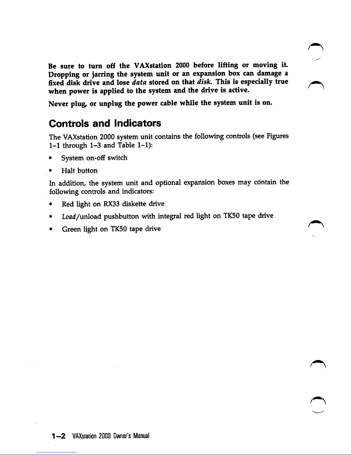
Controls
and
Indicators
The
VAXstation
2000
systemunit contains the
following
controls
(see
Figures
1-1 through
1-3
and Table 1-1):
• System
on-o£f
switch
•
Halt
button
In
addition,
the
system
unit and
optional
expansion
boxes
may
contain
the
following controls and indicators:
• Red light on
RX33
diskette drive
• Load/unload pushbutton withintegral red lighton
TK50
tape
drive
• Green light on
TK50
tape drive
1
-2
VAXstaticn
2000
Owner's
Manual
Figure
1-1:
System Unit On-Off Switch and Diskette Drive Light
SYSTEM
ON-OFF
SWITCH
RX33
DISKETTE
DRIVE
LIGHT
Operating
the
VAXstation
2000
1-3
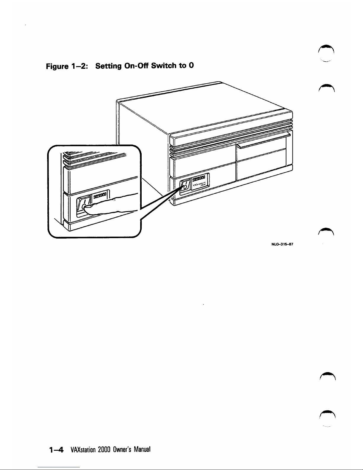
Figure 1
—2:
Setting
On-Off Switcfi
to
0
1—4
VAXstation
2000
Owner's
Manual

Figure1-3:
Halt
Button
—
Rear
of
System
Unit
CABLE
RESTRAIMNG
BAR
HALT
BUTTON
Table
1-1:
Controls
and
Indicators
Control
or
Indicator
System on-off switch
Halt
button
Function
Controls ac power. Setting this switch to 0 (see Fig
ure 1-2) turns off system power. Setting the switch to 1
turns on
the
power.
The expansion box has its
own
on-off switch.
Stops the normal operation of any software and puts the sys
tem in console
mode.
See Figure 1-3. The halt but
ton is a momentary-contact pushbutton.
Console mode lets the user control certain system fimc-
tions that are usually controlled by operating sys
tem
software.
When
the
VAXstation
2000
is
in
con
sole mode, the user types commands at the con
sole prompt\C»>),
The
halt
button
and
console
commands
are
discussed
fur
ther
in
this
manual.
Operating
the
VAXsiation
2000
1-5
Table
1-1
(Cont.):
Controlsand Indicators
Control
or
Indicator
Function
Note:
Pressing
the
halt
button
may
cause
un
saved
data
to
be
lost.
See
your
software
documenta
tion
for
more
information.
Diskette drive light Glows red when the drive is active.
Tape drive This
load/unload
button controls the loading and unloadwith pushbutton inte- ing of tape cartridges. This button is described in degral red light tail later in this chapter.
Tape drive green light Glows steadily to indicate either that the tape drive
is ready for use or that the tape has been suc
cessfully loaded. This light is described in de
tail later in this chapter.
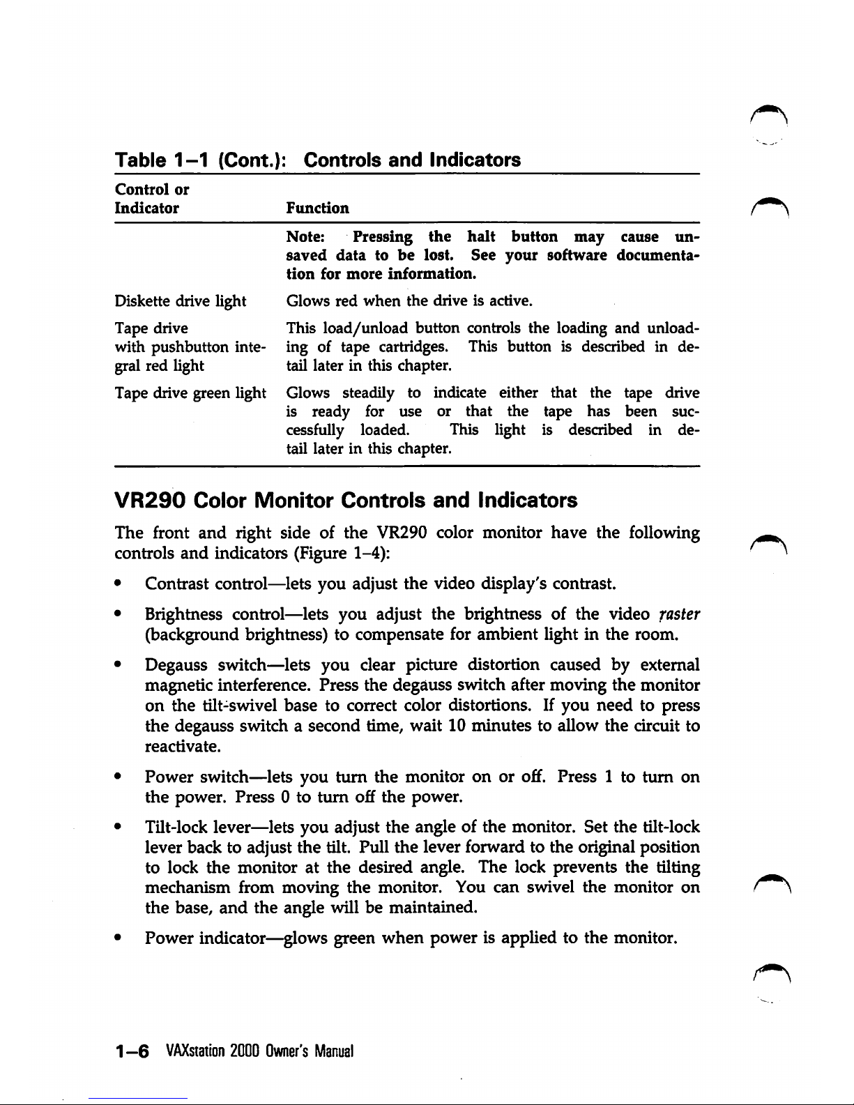
VR290
Color
Monitor
Controls
and
Indicators
The front and right side of the VR290 color monitor have the following
controls
and
indicators (Figure 1-4):
• Contrast control—lets you adjust the video display's contrast.
• Brightness control—lets you adjust the brightness of the video faster
(background brightness) to compensate for ambient light in the room.
• Degauss switch—lets you clear picture distortion caused by external
magnetic interference. Press the degauss switch after moving the monitor
on the tilt-swivel base to correct color distortions. If you need to press
the degauss switch a second time, wait 10 minutes to allow the circuit to
reactivate.
• Power switch—lets you turn the monitor on or off. Press 1 to turn on
the
power. Press 0 to turn off
the
power.
• Tilt-lock lever—lets you adjust the angle of the monitor. Set the tilt-lock
lever back to adjust the tilt. Pull
the
lever forward to the original position
to lock
the
monitor at
the
desired angle. The lock prevents the tilting
mechanism from moving
the
monitor. You can swivel the monitor on
the base,
and
the angle will be maintained.
• Power indicator—glows green when power is applied to the monitor.
1 —6
VAXstation
2000
Owner's
Manual
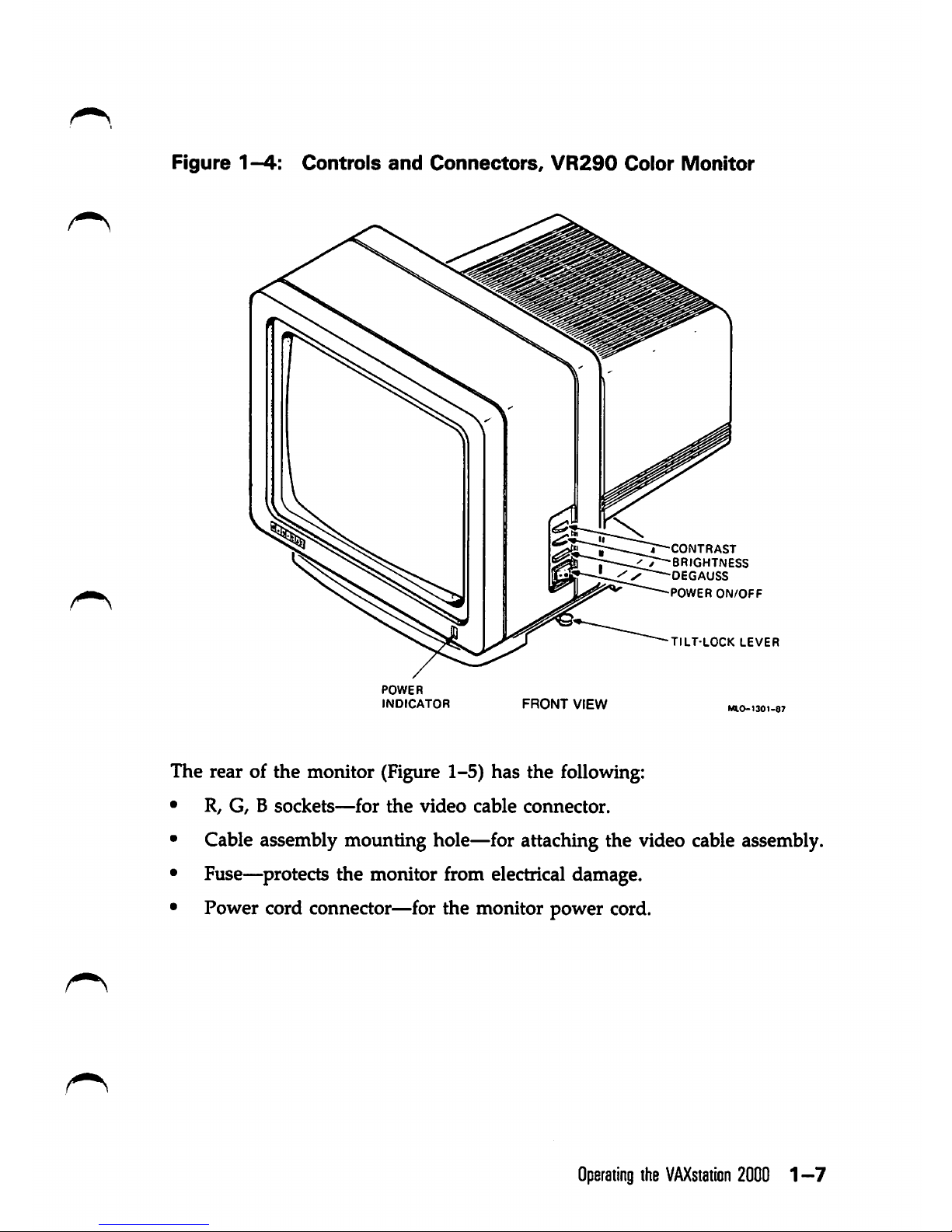
Figure1-4:
Controls
and
Connectors,
VR290
Color
Monitor
^CONTRAST
T^BRIGHTNESS
DEGAUSS
POWER
ON/OFF
TILT-LOCK
LEVER
POWER
INDICATOR
FRONT
VIEW
The rear of the monitor (Figure 1-5) has the following:
• R,
G,Bsockets—for
the
video
cable
connector.
• Cable assembly mounting hole—for attaching the video cable assembly.
• Fuse—^protects the monitor from electrical damage.
• Power cord connector—for the monitor power cord.
Operating
the
VAXstaiicn
20001-7
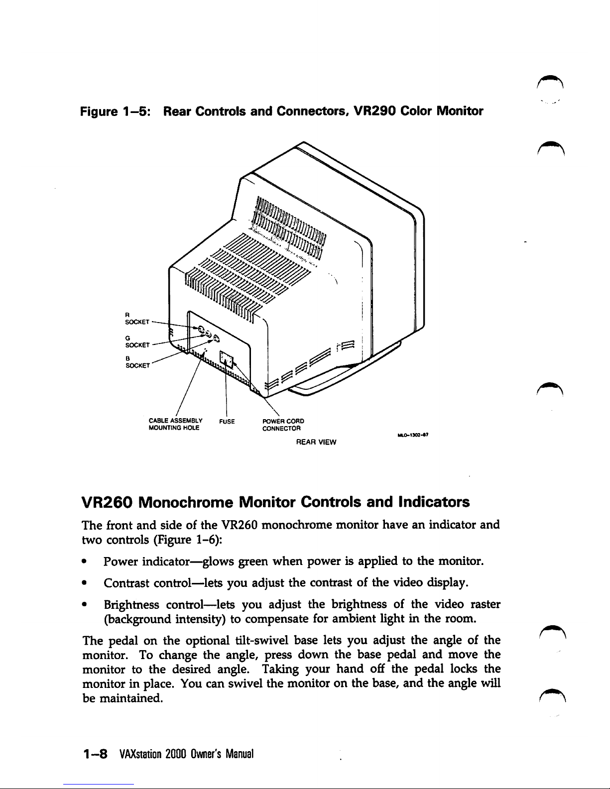
Figure1-5:
Rear
Controls
and
Connectors,
VR290
Color
Monitor
G
SOCKET
B
SOCKET
CABLE
ASSEMBLY
MOUNTING
HOLE
POWER
CORD
CONNECTOR
REAR
VIEW
VR260
Monochrome
Monitor
Controls
and
Indicators
The
front
and
side
of
the
VR260
monochrome
monitor
have
an
indicator
and
two
controls (Figure 1-6):
• Power indicator—glows green when power is applied to the monitor.
• Contrast control—lets you adjust the contrast of the video display.
• Brightness control—lets you adjust the brightness of the video raster
(background intensity) to compensate for ambient light in the room.
The pedal on the optional tilt-swivel base lets you adjust the angle of the
monitor. To change the angle, press down the base pedal and move the
monitor to the desired angle. Taking your hand off the pedal locks the
monitor in place. You can swivel the monitor on the base, and the angle will
be
maintained.
1 —8
VAXstation
2000
Owner's
Manual

Figure
1-6;
Front
and
Right
Side
Controls,
VR260
iUonochrome
Monitor
TILT-SWIVEL
BASE
PEDAL
POWER
INDICATOR
FRONT
VIEW
BRIGHTNESS
CONTROL
CONTRAST
CONTROL
The rear of the
monitor
has the
following
six
connectors
and
controls
(Figure 1-7):
•
On-o£f
switch—lets you controlac power to the monitor. Press 1 to turn
on the power. Press 0 to turn off the
power.
• Power cord connector—for the monitor power
cord.
•
Voltage
select
switch—lets
you
match
the
monitor
operating
voltage
to
the ac line voltage.
•
Fuse—protects
the monitor
from
electrical
damage.
•
Cable
assembly
connector—for
attaching
the
video
cable
assembly
from
the
video
cable.
• Composite video connector—for the video cable from the video cable
assembly.
Operating
the
VAXstaiicn
2000
1-9
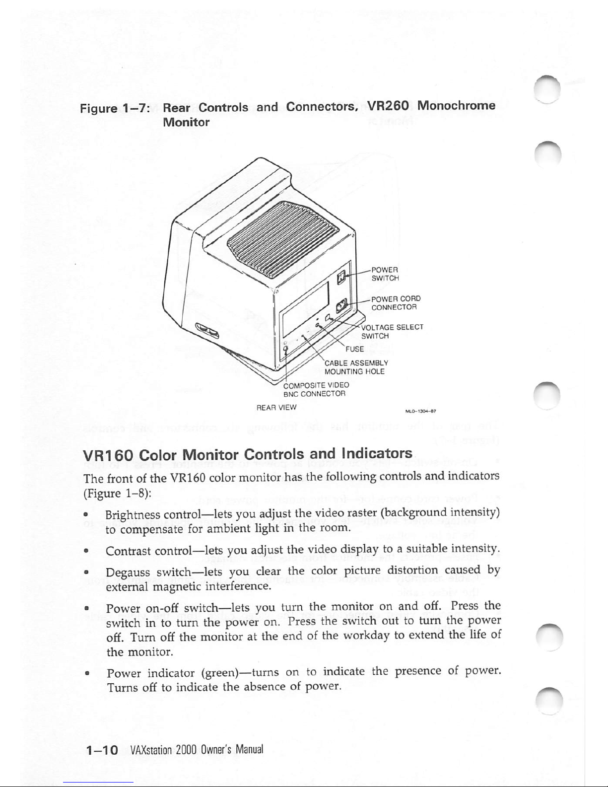
Figure
1-7:
Rear Controls and Connectors, VR260 Monochrome
Monitor
POWER
CORD
CONNECTOR
VOLTAGE
SELECT
SWITCH
CABLE
ASSEMBLY
MOUNTING
HOLE
COMPOSITE VIDEO
BNC CONNECTOR
VR160
Color
Monitor
Controls
and
Indicators
The front of the VR160 color monitor has the following controls and indicators
(Figure 1-8):
•
Brightness
control—lets
you
adjust
the
video
raster
(background
intensity)
to compensate for ambient light in the
room.
•
Contrast
control—lets
you
adjust
the
video
display
toa
suitable
intensity.
•
Degauss
switch—lets
you
clear
the
color
picture
distortion
caused
by
external magnetic interference.
•
Power
on-off
switch—lets
you turn the
monitor
on and
off.
Press
the
switch
in to turn the
power
on.
Press
the
switch
out to turn the
power
off. Turn off the monitor at the end of the workday to extend the life of
the
monitor.
•
Power
indicator
(green)—turns
on to
indicate
the
presence
of
power.
Turns off to indicate
the
absence of power.
1-10
VAXsiation
2000
Owner's
Manual
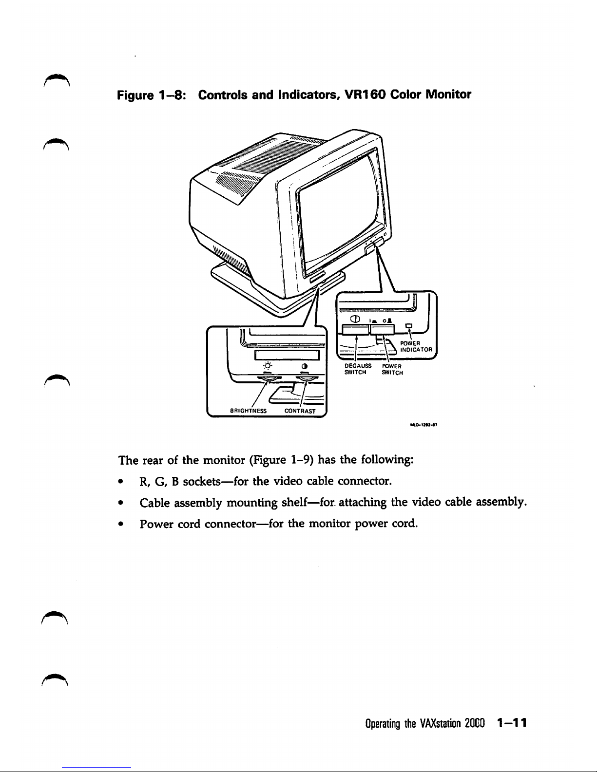
Figure
1-8:
Controls
and
Indicators,
VR160
Color Monitor
BRIGHTNESS
CONTRAST
POWER
INDICATOR
DEGAUSS
POWER
SWITCH SWITCH
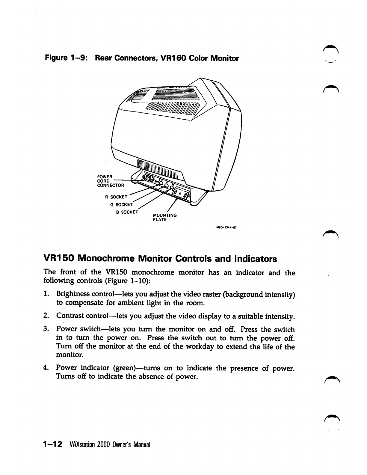
The rear of the monitor (Figure 1-9) has the following:
• R, G, B
sockets—for
the
video
cable
coimector.
• Cable assembly mounting
shelf—for.
attachingthe video
cable
assembly.
•
Power
cord connector—for
the
monitor
power
cord.
Operating
the
VAXstation
2000
1-1
1
Figure
1-9:
Rear
Connectors,
VR160
Color
Monitor
POWER
CORD
CONNECTOR
R
SOCKET
G
SOCKET
B
SOCKET
7&
MOUNTING
PLATE
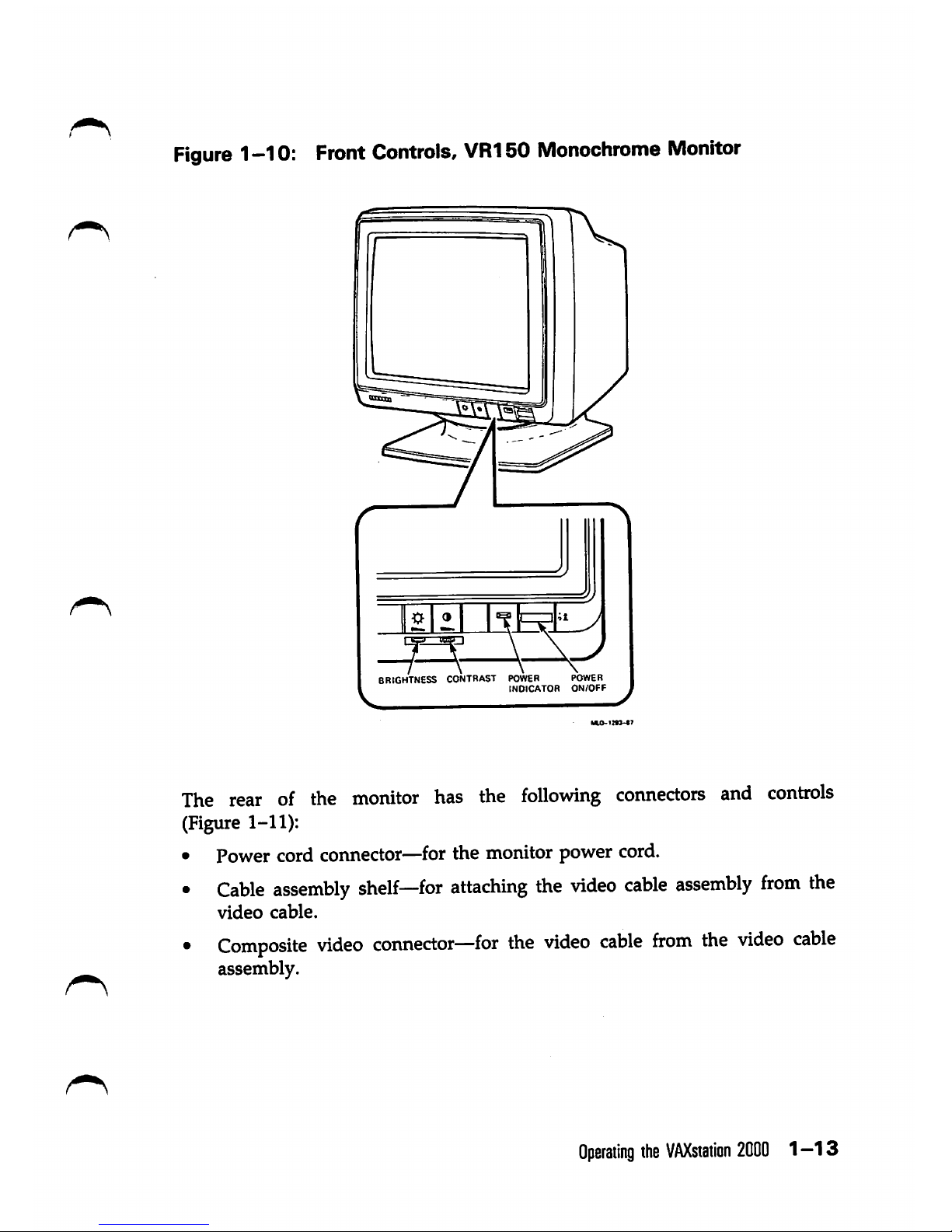
VR150
Monochrome
Monitor
Controls
and
Indicators
The
front
of
the
VR150
monochrome
monitor
has
an
indicator
and
the
following controls (Figure 1-10):
1.
Brightness
control—lets
youadjustthe videoraster
(background
intensity)
to compensate for ambient light in the room.
2. Contrast
control—lets
youadjustthe
video
display
toa
suitable
intensity.
3. Power switch—lets you turn the monitor on and off. Press the switch
in to turn the power on. Press the switch out to turn the power off.
Turn off the monitor at the end of the workday to extend the life of the
monitor.
4. Power indicator (green)—turns on to indicate the presence of power.
Turns off to indicate the absence of power.
1-12
VAXsiation
2000
Owner's
Manual
Figure
1-10:
Front
Controls,
VR150
Monochrome
Monitor
1
15B
1
/ \
\ \
\
, J
\
BRIGHTNESS CONTRAST POWER POWER
INDICATOR
ON/OFF
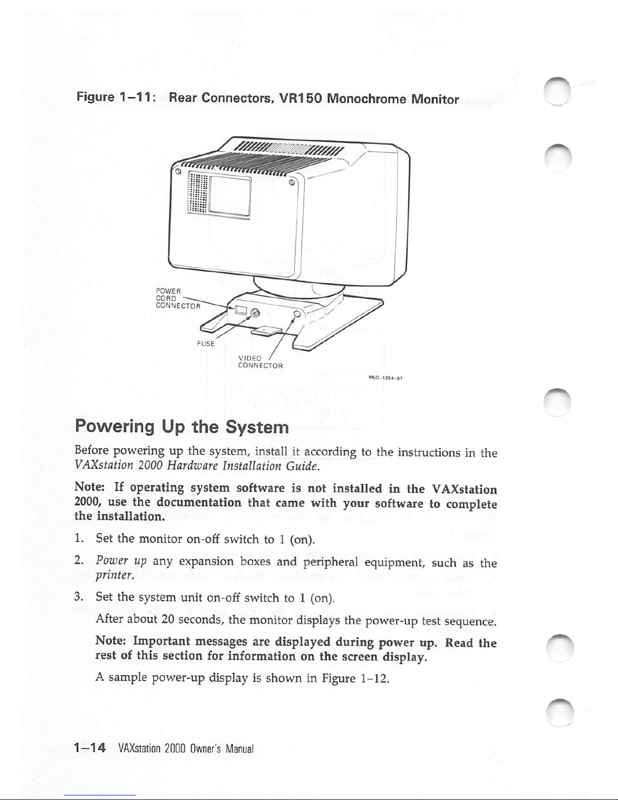
The
rear of the
monitor
has the
following
connectors
and
controls
(Figure 1-11):
• Power cord connector—for the monitor power cord.
•
Cable
assembly
shelf—for
attaching
the
video
cable
assembly
from
the
video
cable.
•
Composite
video
connector—for
the
video
cable
from
the
video
cable
assembly.
Operating
the
VAXstaiion
2000
1—13
Figure
1—11:
Rear
Connectors,
VR150
Monochrome
Monitor
POWER
CORD
CONNECTOR
VIDEO
/
CONNECTOR
Powering
Up
the
System
Before
powering
up the
system,
installitaccording
to the
instructions
in the
VAXstation
2000
Hardware
Installation
Guide.
Note: If
operating
system software is
not
installed
in
the
VAXstation
2000,
use the documentation that came with your software to complete
the
installation.
1. Set the monitor on-off switch to 1 (on).
2.
Power
up
any
expansion
boxes
and
peripheral
equipment,
such
as the
printer.
3. Set the system unit on-off switch to 1 (on).
After
about
20
seconds,
the
monitor
displays
the
power-up
test
sequence.
Note: Important messages are displayed during power up. Read the
rest of this section for information on the screen display.
A sample power-up display is shown in Figure1-12.
1—14
VAXstation
2000
Owner's
Manual
iCaution:
Do not power downthe
VAXstation
2000
until power-uptesting
is
complete.
Wait
until
you
seeeitherthe
console
prompt
(»>) orthe
first
screen
of your operating
system
software.
Powering
down
before
testing
is complete may destroy data in the system's nonvolatile random-access
memory.
Caution: Power up any expansionboxes before powering up the system
unit so that any tapes or disks can be included in the configuration.
Table
1-2
lists
the system's
normal
power-up
indications.
The
table
includes
indicators
on
optional
equipmentaswell.
Your
system
may
not
contain
all
the
listed
devices.
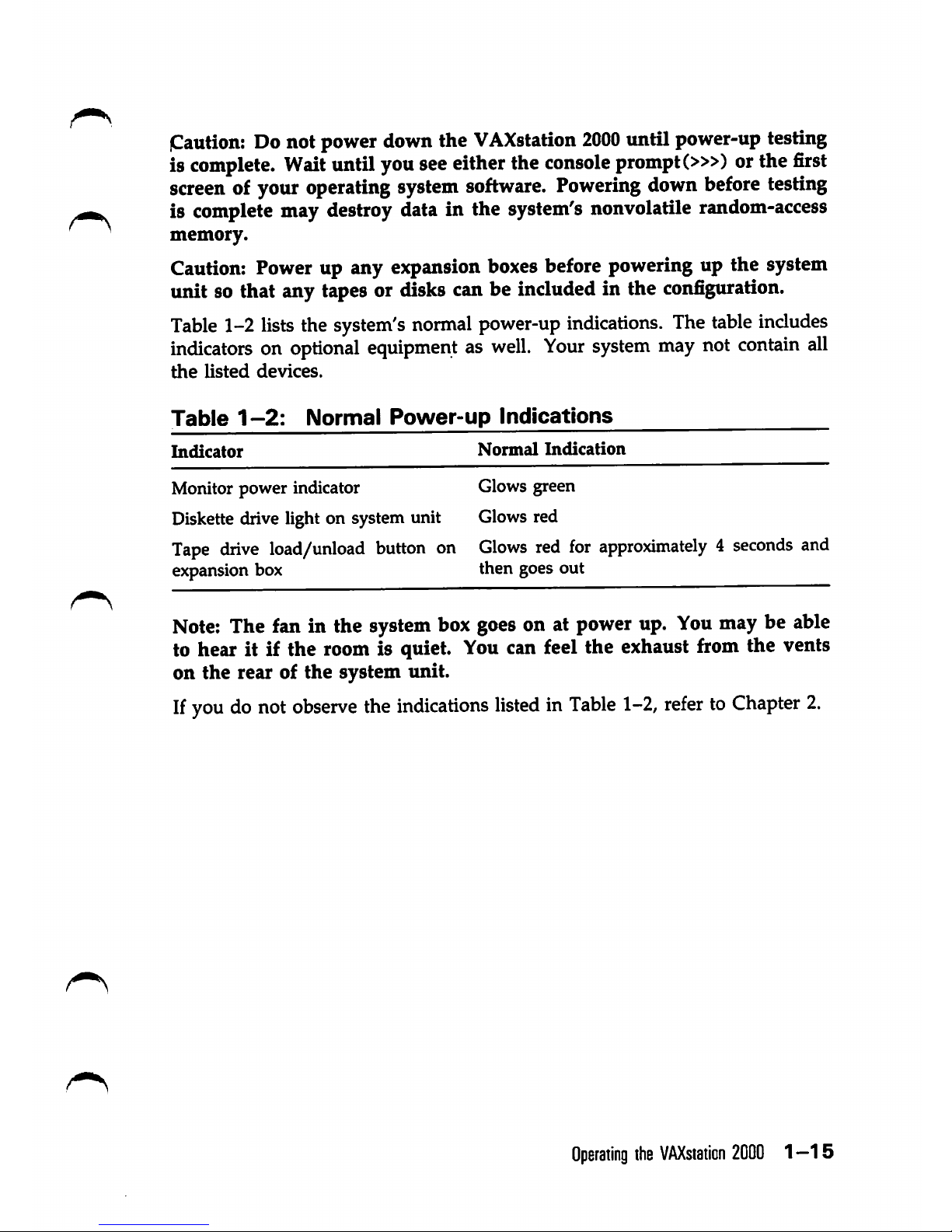
Table
1-2:
Normal
Power-up
Indications
Indicator
Normal
Indication
Monitor
power
indicator
Glows green
Diskette drive light on system unit
Glows
red
Tape drive load/unload button on
Glows red for approximately 4 seconds and
expansion box
then
goes
out
Note;
The fan in the
system
box
goes
on at
power
up.
You
may be able
to hear it if the room is quiet. Youcan feel the exhaust from the vents
on
the
rear of the system unit.
If
you
donot
observe
the
indications
listedinTable
1-2,
refertoChapter
2.
Operating
the
VAXstation
2000
1—15
Figure
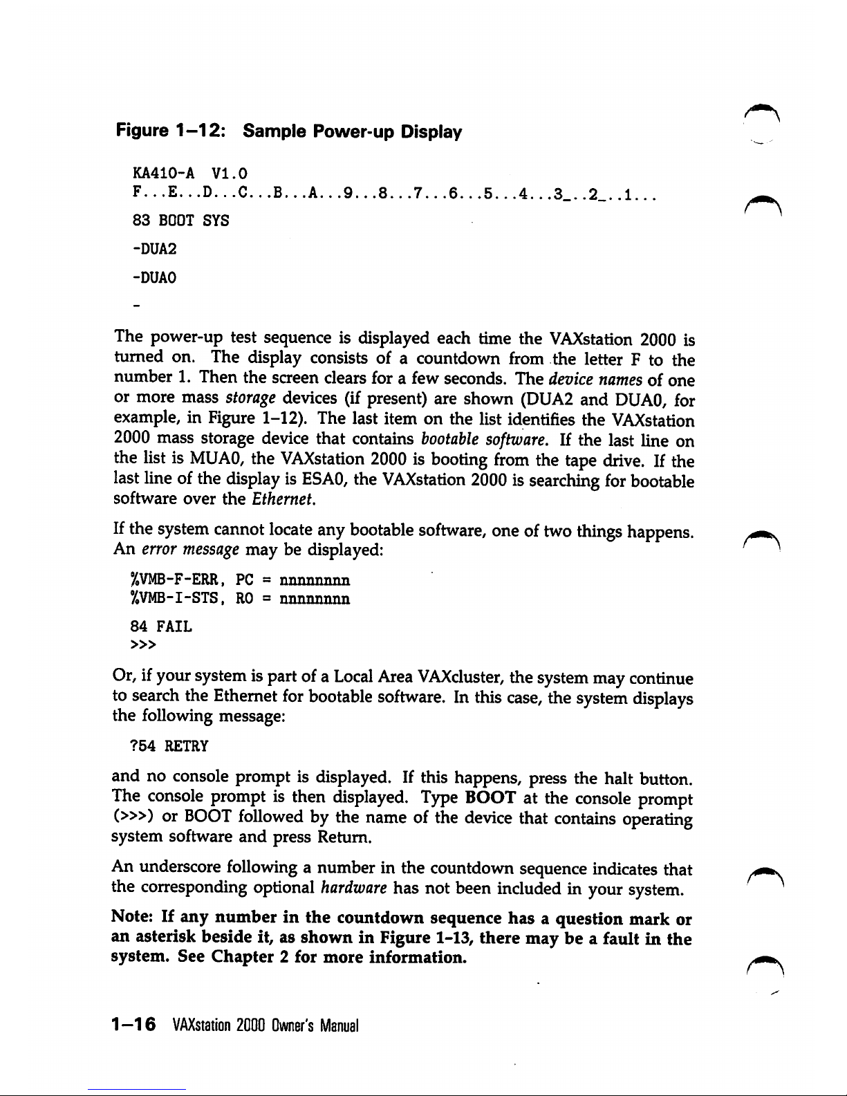
1-12:
Sample
Power-up
Display
KA410-A
VI.0
F...E...D...C...B...A...9...8...7...6.
83
BOOT
SYS
-DUA2
-DUAO
The power-up test sequence is displayed each time the
VAXstation
2000 is
turned on. The display consists of a countdown from the letter F to the
number
1.
Then
the
screen clears for a few seconds.
The
device names of
one
or more mass storage devices (if present) are shown (DUA2 and
DUAO,
for
example, in Figure 1-12). The last item on the list identifies the
VAXstation
2000 mass storage device that contains
bootable
software.
If the last line on
the listis
MUAO,
the
VAXstation
2000isbooting
from
the tape
drive.
If the
last
line
ofthe
displayisESAO,
the
VAXstation
2000issearching
for
bootable
software
over
the
Ethernet.
Ifthe
system
cannot
locate
any
bootable
software,
oneoftwo
things
happens.
An error
message
may be displayed:
%VMB-F-ERR,
PC =
nnnnnnnn
%VMB-I-STS,
RO=nnnnnmin
84
FAIL
»>
Or,ifyour
system
ispartofa
Local
Area
VAXcluster,
the
system
may
continue
to
search
the
Ethernet
for
bootable
software.
In
this
case,
the
system
displays
the following message:
?54
RETRY
and no console prompt is displayed. If this happens, press the halt button.
The
console
promptisthen
isplayed.
Type
BOOTatthe
console
prompt
(»>) or
BOOT
followed
bythe
nameofthe
device
that
contains
operating
system software
and
press Return.
An underscorefollowing a number in the countdown sequenceindicatesthat
the
corresponding
optional
hardware
has not been
included
in your
system.
Note: If any number in the countdown sequence has a question mark or
an asterisk beside it, as shown in Figure 1-13, there may be a fault in the
system.
See
Chapter
2 for
more
information.
1-16
VAXstation
2000
Owner's
Manual
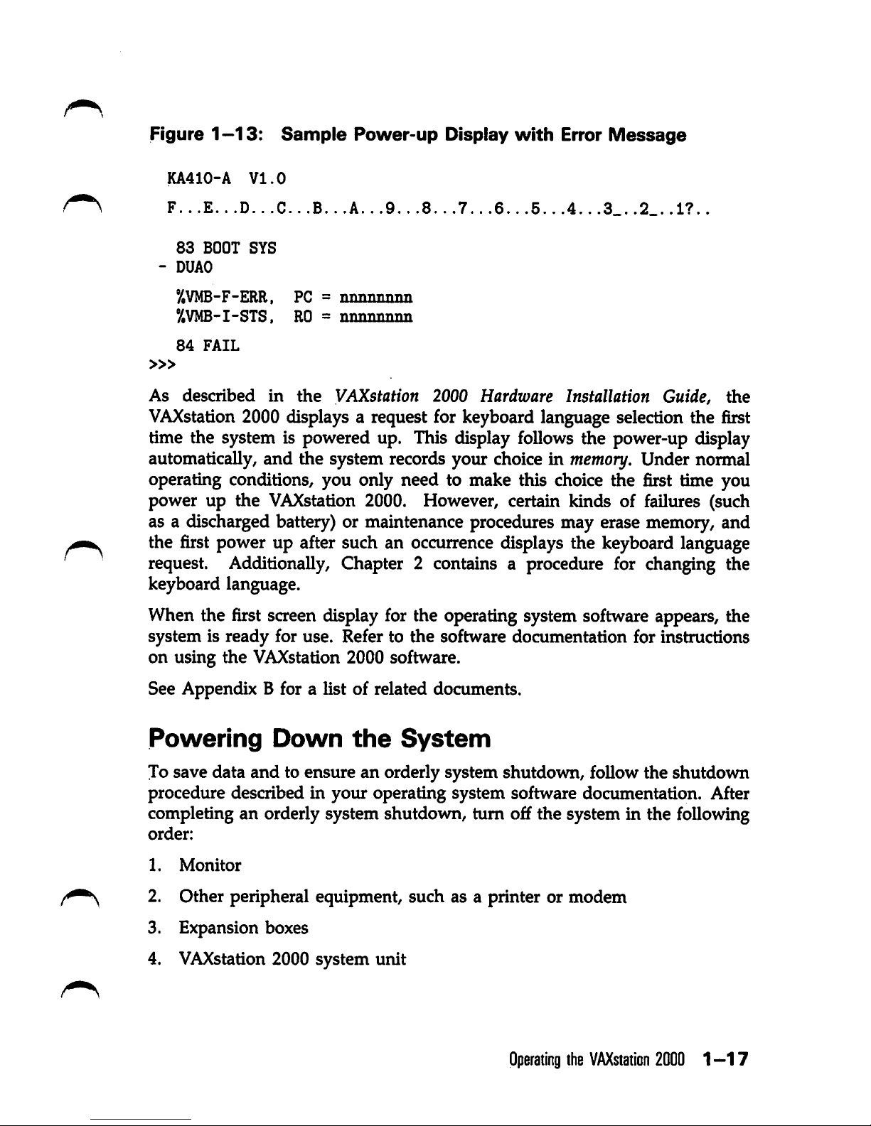
Figure
1-13:
Sample
Power-up
Display
with
Error
Message
KA410-A
VI.0
F...E..
.D..
.C..
.B..
.A..
.9..
.8...7..
.6.. .5..
.4..
.3_.
.2_.
.1?..
83
BOOT
SYS
- DUAO
°/.VMB-F-ERR,
PC =
nnnnnnim
y,VMB-I-STS,
RO=nnnnnnnn
84
FAIL
»>
As
described
m
the
VAXstation 2000
Hardware
Installation Guide,
the
VAXstation
2000 displays a request for keyboard language selection the first
time the system is powered up. This display follows the power-up display
automatically,
and
^e
system
records
your
choiceinmemory.
Under
normal
operating conditions, you only need to make this choice the first time you
power up the VAXstation 2000. However, certain kinds of failures (such
as a discharged battery) or maintenance procedures may erase memory, and
the first power up after such an occurrence displays the keyboard language
request. Additionally, Chapter 2 contains a procedure for changing the
keyboard language.
When the first screen display for the operating system software appears, the
system is ready for use. Refer to the software documentation for instructions
on using the VAXstation 2000 software.
See Appendix B for a list of related documents.
Powering
Down
the
System
To save data
and
to ensure an orderly system shutdown, follow the shutdown
procedure described in your operating system software documentation. After
completing an orderly system shutdown, turn off the system in the following
order:
1.
Monitor
^ 2- Other peripheral equipment, such as a printer or modem
3. Expansion boxes
4. VAXstation 2000 system
unit
Operating
the
VAXstation
2000
1-17
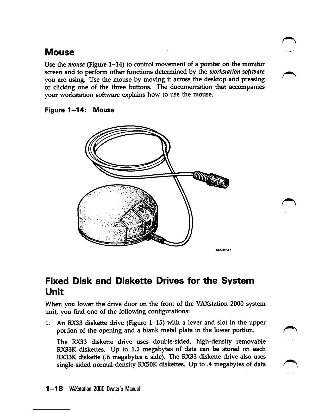
Mouse
Use the
mouse
(Figure1-14) to control movement of a pointer on the monitor
screen and to perform other functions determined by the
workstation
software
you are using. Use the mouse by moving it across the desktop and pressing
or clicking one of the three buttons. The documentation that accompanies
your workstation software explains how to use the mouse.
Figure
1-14:
Mouse
Fixed
Disk
and
Dislcette
Drives
for
the
System
Unit
When you lower the drive door on the front of the
VAXstation
2000 system
unit, you find one of the following configurations:
1. An
RX33
diskette drive (Figure 1-15) with a lever and slot in the upper
portion of the opening and a blank metal plate in the lower portion.
The RX33 diskette drive uses double-sided, high-density removable
RX33K
diskettes. Up to 1.2 megabytes of data can be stored on each
RX33K
diskette (.6 megabytes a side). The
RX33
diskette drive also uses
single-sided normal-density
RX50K
diskettes. Up to .4 megabytes of data
1-18
VAXstation
2000 Owner's
Manual
 Loading...