


DIGITAL Mul tiSwit ch 700EL
DLE28-MA
Interface Module User’s Guide


DIGITAL Mul tiSwit ch 700EL
DLE28-MA
Interface Module User’s Guide
Part Number: 9032616
September 1998
This manual describes how to use the DLE28-MA DIGITAL MultiS witch
700EL module.
Revisi on/ Update Info rmation :
Th is is a new documen t.

Cabletron Systems res erves the r ight to make changes in speci f ication s a nd other information
contained in this document without prior notice. The reader should in all cases consult Cabletron
Systems to determine whether any such changes have be en made.
The hardware, firmware, or software described in this manual is subject to change without notice.
IN NO EVENT SHALL CABLETRON SYSTEMS BE LIABLE FOR ANY INCIDENTAL,
INDIRECT, SPECIAL, OR CONSEQUENTIAL DAMAGES WHAT SOEVER (INCLUDING BUT
NOT LIMITED TO LOST PROFITS) ARISING OUT OF OR RELATED TO THIS MANUAL OR
THE INFORMATION CONTAINED IN IT, EVEN IF CABLETRON SYSTEMS HAS BEEN
ADVISED OF, KNOWN, OR SHOULD HAVE KNOWN, THE POSSIBILITY OF SUCH
DAMAGES.
Copyright 1998 by Cabletron Systems, In c., P.O. Box 5005, Roches ter, NH 03866- 5005
All Rights Reserved
Printed in the United States of America
SPECTRUM, LANVIEW are registered trademarks of Cable tron System s , Inc.
DIGITAL and the DIGITAL lo go are trad em ar ks of Digita l Equip m ent Corpora ti on.
All other product names mentioned in this manual may be tradema rk s or register ed trademarks of
their respective companies.
UNITED STATES GOVERNMENT RESTRICTED RIGHTS
The enclosed product ( a ) w as developed solely at private expense; (b) contains “restricted comput er
software” submitted with restricted rights in accordance with Section 52227-19 (a) through (d) of the
Commercial Computer Software - Restricted Rights Clause and its successors, and (c) in all respects
is propri etary data belonging to Cabletron and/or its suppliers.
For Department of Defense units, the product is licensed w ith “Restricted Rights” as defi ned in the
DoD Supplement to the Federal Acquisition Regulations, Section 52.227-7013 (c) (1) (ii) and its
successors, and use, duplication, disclosure by the Government is subject to restrictions as set forth in
subparagraph (c) (1) (ii) of the Rights in Technical Data and Computer Software clause at
252.227-7013. Cabletron Systems, Inc., 35 Industrial Way, Rochester, New Hampshire 03867-0505.
FCC Notice — Class A Computing Device:
This equipment generates, uses, and may emit radio frequency energy. The equipment has been typ e
tested and found to compl y w it h the limits f or a Clas s A digital device purs uant to Part 15 of FCC
rules, which are designed to pro vide reasonable prot ection against such radio frequency interference.
Operation of this equipment in a residential area may cause interference in which case the user at his
own e xpense will be require d to take whatever measures may be req uired to correct the interference.
Any modif ic atio ns to thi s de vice - unless e xpr es sly appr ov ed b y the manu fact urer - can v oid the us er's
authority to operate this equipment under par t 15 of the FCC r ules.
DOC Notice — Class A Computing Device:
This digit al apparatus does not exceed t he Class A limit s for radio noise emiss ions from digital
apparatus set out in the Radio Interference Regulations of the Canadian Department of
Communications.
Le présen t appareil numérique n’émet pas d e bruits radioélectriques dépassant les l imites applicables
aux appareils numériques de la class A prescrites dans le Règlement sur le brouillage radioélectrique
édicté par l e ministère des Communications du Canada.
VCCI Notice — Class A Computing Device:
Taiwanese Notice — Class A Computing Device:
CE Notice — Class A Computing Device:
Warning!
This is a Class A product. In a domestic environment, thi s pr oduct may cause r a dio interference, in
which case the user may be required to take adequate measures.
Achtung!
Dieses ist ein Gerät der Funkstörgrenzwertklasse A . In Wohnbere ichen kön nen bei Betrieb dieses
Gerätes Ru ndfunkstörunge n auftreten, in welchen Fällen der Benutzer für entsprechende
Gegenma
Avertissement!
Cet appareil est un appareil de Classe A. Dans un environnement rés identiel cet appareil peut
provoquer des brouillages radioélectriques. Dans ce cas, il peut être demandé à l'utilisateur de prendre
les mesures appropriées.
nahmen verantwortlich ist.
ß

CABLETRON SYSTEMS, INC. PROGRAM LICENSE AGREEMENT
IMPORTANT: Before utilizing this product, carefully read this License Agreement.
This do cument is an agreement between you, the end user, and Cabletron Sys tems, Inc. (“Ca bletron”)
that sets forth your rights and obligations with respect to the Cabletron software program (the
“Program”) contained in this package. The Program may be contained in firmwar e, chips or other
media. BY UTILIZING THE ENCLOSED PRODUCT, YOU ARE AGREEING TO BECOME
BOUND BY THE TERMS OF THIS AGREEMENT, WHICH INCLUDES THE LICENSE AND
THE LIMITATION OF WARRANTY AND DISCLAIMER OF LIABILITY. IF YOU DO NOT
AGREE TO THE TERMS OF THIS AGREEMENT, PROMPTLY RETURN THE UNUSED
PRODUCT TO THE PLACE OF PURCHASE FOR A FULL REFUND.
CABLETRON SOFTWARE PROGRAM LICENSE
1. LICENSE. You ha ve the right to use only the one (1 ) copy of the P rogram provi ded in this
package subject to the terms and conditions of this License Agreement.
You may not copy, reproduce or transmit any part of the Program except as permitted by the
Copyri ght Act of the Uni ted States or as authori zed in writing by Cabletr on.
2. OTHER RESTRICTIONS
Program.
3. APPLICABLE LA W
and in the stat e and federa l courts of Ne w Ham ps hire. You accept the personal jurisdiction and
venue of the New Hampshire courts.
. Y ou may not reverse engineer , decompile, or disassemble the
. T his Li cense Agr eemen t sha ll be int erpret ed and gov erned u nde r the l aws
EXCLUSION OF WARRANTY AND DISCLAIMER OF LIABILITY
1. EXCLUSION OF WARRANTY. E xcept as may be specifically provided by Cabletron in
writing, Cabl etron make s no w arran t y, expr e ssed or imp lied , conce rn ing t he Pr ogra m (in cludi ng
its documen tation and media).
CABLETRON DISCLAIMS ALL W ARRANTIES, OT HER THAN THOSE SUPPLIED TO
YOU BY CABLETRON IN WRITING, EITHER EXPRESSED OR IMPLIED, INCLUDING
BUT NOT LIMITED TO IMPLIED WARRANTIES OF MERCHANTABILITY AND
FITNESS FOR A PARTICULAR PURPOSE, WITH RESPECT TO THE PROGRAM, THE
ACCOMPANYING WRITTEN MATERIALS, AND ANY ACCOMPANYING HARDWARE.
2. NO LIABILITY FOR CONSEQUENTIAL DAM AGES
CABLETRON OR ITS SUPPLIERS BE LIABLE FOR ANY DAMAGES WHATSOEVER
(INCLUDING, WITHOUT LIMITATION, DAMAGES FOR LOSS OF BUSINESS,
PROFITS, BUSINESS INTERRUPTION, LOSS OF BUSINESS INFORMATION, SPECIAL,
INCIDENTAL, CONSEQUENTIAL, OR RELIANCE DAMAGES, OR OTHER LOSS)
ARISING OUT OF THE USE OR INABILITY TO USE THIS CABLETRON PRODUCT,
EVEN IF CABLETRON HAS BEEN ADVISED OF THE POSSIBILITY OF SUCH
DAMAGES. BECAUSE SOME STATES DO NOT ALLOW THE EXCLUSION OR
LIMITATION OF LIABILITY FOR CONSEQUENTIAL OR INCIDENTAL DAMAGES, OR
ON THE DURATION OR LIMITATION OF IMPLIED WARRANTIES, IN SOME
INSTANCES THE ABOVE LIMITATIONS AND EXCLUSIONS MAY NOT APPLY TO
YOU.
. IN NO EVENT SHALL

SAFETY INFORMATION
CLASS 1 LASER TRANSCEIVERS
THE DELF3-UI FAST ETHERNET INTERFACE MODULE, DEL05-UI
FDDI PORT INTERFACE MODULE, AND DEL29-UI ATM PORT INTER-
FACE MODULE USE CLASS 1 LASER TRANSCEIVERS. READ THE
FOLLOW I NG SAFETY INF OR M A TION BEFO RE
INSTALLING OR OPERATING THESE MODULES.
The Class 1 laser transceivers use an optical feedback loop to maintain Class 1 operation limits. This
control loo p el imina tes the need for main tenanc e check s or adj ustmen ts. The outp ut is fac tor y set, an d
does not allow any user adjustment. Class 1 laser transceivers comply with the following safety
standards:
• 21 CFR 1040.10 and 1040.11 U.S. Department of Health and Human Services (FDA).
• IEC Publica tio n 825 (Intern a tional Electrotech nical Co mmi ss ion).
• CENELEC EN 60825 (European Committee for Electro technical Standard ization).
When operating within their performance limitations, laser transceiver output meets the Class 1
accessible emission limit of all three standar ds. Class 1 levels of laser radiation are not considered
hazardous.
SAFETY INFORMATION
CLASS 1 LASER TRANSCEIVERS
LASER RADIATION AND CONNECTORS
When the connect or is in place, all laser radiation remains within the fiber. The maximum amount of
radiant power exiting the fibe r (under norm al conditions) is -12.6 dBm or 55 x 10
Removing the optical connector from the transceiver allows laser radiation to emit directly from the
optical port. The maximum radiance from the optical port (under worst case conditions) is
0.8 W cm
Do not use optical instruments to vie w th e laser output. The use of opt ical inst ruments to view
laser output increases eye hazard. When vi ew ing the output optical port, power must be
removed from the network adapter.
-2
or 8 x 10³ W m2 sr-1.
-6
watts.

DECLARATION OF CONFORMITY
Application of Council Directive(s): 89/336/EEC
73/23/EEC
Manufacturer’s Name: Cabletron Systems, Inc.
Manufac ture r’s Address: 35 Industrial Way
PO Box 5005
Rochester, NH 0386 7
European R e presentative Name: Mr. J. Solari
European Representative Address: Cabletron Systems L imited
Nexus House, Newbury Business Park
London Road, Newbury
Berkshire RG13 2PZ, England
Conformanc e to Directi v e(s)/Product Standards: EC Directive 89/336/EEC
EC Directive 73/23/EEC
EN 55022
EN 50082-1
EN 60950
Equipment Type/Environment: Networking Equipment, for use in a
Commercial or Light Industrial
Environm ent.
W e the und ersi gned , here by decla re, un der our sole re spon sibi lity, that the equipment pac kage d
with this notice conforms to the above directives.
Manufacturer Legal Representative in Europe
Mr. Ronald Fotino Mr. J. Solari
___________________________________ ___________________________________
Full Name Full Name
Principal Compliance Engineer Managing Director - E.M.E.A.
___________________________________ ___________________________________
Title Title
Rochester, N H, USA Newbury, Berkshire, England
___________________________________ ___________________________________
Location Location

CONTENTS
PREFACE
Using This Guide..........................................................................xiii
Structure of This Guide.................................................................xiii
Document Con ve ntion s................................................................xiv
Related Documentation...............................................................xv
Correspondence...................... . .. .............. .. . .............. .. .. ............. ..x v
Documentation Commen ts..............................................xv
World Wide Web..............................................................xv
Getting Help.................................................................................xvi
SAFETY
Overview.....................................................................................xvii
Safety Require men ts..................................................................xviii
CHAPTER 1 INTRODUCTION
1.1 DLE28-MA Overview...................................................................1-1
1.1.1 Connectivity..... ..................................... ..........................1-3
1.1.2 Full Duplex Switched Ethernet........................................1-3
1.1.3 Management.................................. .................................1-3
1.1.4 Switching Options...........................................................1-3
1.1.5 Standard s Co mp a tib ility..................................................1- 3
1.1.6 LANVIEW Diagnostic LEDs............................................1-4
1.1.7 Year 200 0 Co mplia n t......................................................1 - 4
1.1.8 Runtime IP Address Discovery.......................................1-4
1.2 Local Management Features.... .. ... .. .... . .... .. ... .. ... .. ... .. .... . .... .. ... .. ..1-5
1.2.1 Distributed Chassis Management...................................1-5
1.2.2 Remote Monitorin g (RMON)...........................................1- 5
1.2.3 Broadcast Suppression....... .. ... .. .... . .... .. ... .. ... .. ... .. .... . .... . .1-5
1.2.4 Port Redirect Function....................................................1-6
1.2.5 SmartTrunk.....................................................................1-6
1.2.6 Additional Local Management Functions........................1-6
1.3 Optional Featu r e s........................................................................1 - 7
CHAPTER 2 NETWORK REQUIREMENTS
2.1 SmartTrunk..................................................................................2- 1
2.2 10BASE-F Network.....................................................................2-1
2.3 100BASE-TX Network.................................................................2-2
DLE28-MA User’s Guide vii

Contents
2.4 100BASE-FX Fiber Op tic N e two r k...............................................2 - 2
CHAPTER 3 INSTALLATION
3.1 Required Tools.............................................................................3-1
3.2 Unpacking the DLE28-MA...........................................................3-1
3.3 DLE28-MA Options......................................................................3-2
3.4 Power Sup ply Re qu ire me n ts.......................................................3 -2
3.5 Installing the DLE28-MA Into the DLM6C-AA Chassis................3-2
3.6 Connecting to the Network.. .. ... .... .. ... ... .. .... ... .. ... .... .. ... ... .. .... ... .. ...3-5
3.6.1 Connecting Fiber Optic Cables to
Ports 1 Through 24 of the Modules3-6
3.6.2 Connecting a UTP Segment to the DELTX-UI.. .... .. ... .... . 3-8
3.6.3 Connecting a Fiber Optic Segment
to the DELFX-UI and DELF3-UI3-9
3.7 Completing the Installation.........................................................3-11
CHAPTER 4 TROUBLESHOOTING
4.1 Using LANVIEW...........................................................................4-1
4.2 DELTX-UI LED.............................................................................4-4
4.3 Troubleshooting Checklist.......... .... . .... ... .. ... .... .. ... .... . .... ... .. ... .... .. .4-6
4.4 Using the RESET Button.............................................................4-7
CHAPTER 5 LOCAL MANAGEMENT
5.1 Overview......................................................................................5- 1
5.2 Local Management Keyboard Conventions.................................5-2
5.3 Management Terminal Setup.......................................................5-3
5.3.1 Console Cable Connection..............................................5-3
5.3.2 Connecting an Uninterruptible Power Supply... ... .... . .... ...5-4
5.3.3 Management Terminal Setup Parameters......................5-5
5.3.4 Telnet Connections.........................................................5-6
5.4 Accessing Local Management.....................................................5-7
5.4.1 Navigating Local Management Screens...... ... .. ... .. ... .. .... .5-8
5.4.2 Selecting Local Management Menu Screen Items... .. ...5-10
5.4.3 Exiting Local Management Screens..............................5-10
5.5 The Main Menu Screen..... .. .... . .... .. ... .. ... .. ... .. .... . .... .. ... .. ... .. ... .. ...5-11
5.6 Chassis Menu Scree n................................................................5 - 1 4
5.7 Chassis Configuration Screen...................................................5-16
viii DLE28-MA User’s Guide

Contents
5.7.1 Setting the IP Address..................................................5-18
5.7.2 Setting the Subnet Mask...............................................5-19
5.7.3 Setting the Chassis Date..............................................5-20
5.7.4 Setting the Chassis Time..............................................5-20
5.7.5 Entering a New Screen Refresh Time..... .. ... .... . .... ... .. ..5-21
5.7.6 Setting the Screen Lockout Time.... .. .... ... .. ... .. ... .... .. ... ..5-21
5.7.7 Setting the Operational Mode.......................................5-22
5.8 SNMP Community Names Screen............................................5-24
5.8.1 Establishing Community Names...................................5-25
5.9 SNMP Traps Screen..................................................................5-27
5.9.1 Configuring the Trap Table...........................................5-28
5.10Chassis Envir o nme nta l Scre e n.................................................5 - 2 9
5.11Port Redirect Function Screen..................................................5-30
5.11.1Displaying the Source and Destination Entries........... ..5-32
5.11.2Changing Source and Destination Ports.......................5-33
5.12Module Selection Screen...........................................................5-34
5.12.1Selecting a Module.......................................................5-35
5.13Module Menu Screen.......... .. ... .. ... .. .... . .... .. ... .. ... .. ... .. .... . .... .. ... ..5-36
5.14Module Configuration Menu Screen....... .. ... .. .... . .... . .... ... .. .... . ....5-38
5.15General Configuration Screen...................................................5-40
5.15.1Setting the IP Address..................................................5-44
5.15.2Setting the Subnet Mask...............................................5-45
5.15.3Setting the Default Gateway.........................................5-46
5.15.4Setting the TFTP Gateway IP Address.........................5-46
5.15.5Setting the Module Date...............................................5-47
5.15.6Setting the Module Time...............................................5-48
5.15.7Entering a New Screen Refresh Time..... ... .. .... ... .. ... ....5-48
5.15.8Setting the Screen Lockout Time.... .. .... ... .. ... .. ... .... .. ... ..5-49
5.15.9Setting the Operational Mode.......................................5-50
5.15.10Setting the Management Mode.....................................5-50
5.15.11Configuring the COM Port ............................................5-51
5.15.12Changing the Com Port Application....... .. ... .... .. ... .... . ....5-53
5.15.13Clearin g NVRAM...........................................................5- 5 4
5.15.14Enabling/Disabling IP Fragmentation............................5-55
5.16SNMP Community Names Screen............................................5-56
5.16.1Establishing Community Names...................................5-58
5.17SNMP Traps Screen..................................................................5-59
5.17.1Configuring the Trap Table...........................................5-60
5.18Switch Configuration Screen.....................................................5-60
5.18.1Setting the STA.............................................................5-63
5.18.2Setting the Age Time....................................................5-64
5.18.3Setting (Enabling or Disabling) the Port Status........ ... ..5-64
5.19Ethernet Full Duplex Configuration Screen...............................5-64
DLE28-MA User’s Guide ix

Contents
5.19.1Setting the Operation Mode..........................................5-67
5.20SmartTrunk and the Configuration Screen.. .. .... ... .. ... .... . .... ... .. ... 5-68
5.20.1SmartTrunk Configuration Rules...................................5-68
5.20.2SmartTrunk Configuration Screen.................................5-70
5.20.3Enabling the Connection...............................................5-73
5.20.4Displaying the SmartTrunk Ports...................................5-73
5.21Module Specific Configuration Menu Screen.............................5-74
5.22System Resources Screen........................................................5-77
5.22.1Setting the Reset Peak Utilization.................................5-78
5.23High Speed Interface Configuration Screen (DLE 28-MA Only).5-79
5.23.1Configuring a DELFX-UI or DELF3-UI..........................5-82
5.23.2Setting the DELFX-UI and DELF3-UI
Operational Mode5-82
5.23.3Configuring a DELTX-UI................................................5-83
5.23.4Setting the DELTX-UI Operational Mode......................5-83
5.23.5Setting the DELTX-UI Advertised Ability.......................5-83
5.24Flash Download Screen.............................................................5-84
5.24.1Image File Download Using TFTP................... ... .... . .... .5-86
5.24.2Image File Download Using RUNTIME................... ... .. .5-87
5.24.3Image File Download Using BootP................. ... .. .... ... .. .5-89
5.25Port Redirect Function Screen...................................................5-89
5.25.1Displaying the Source and Destination Entries.............5-91
5.25.2Changing Source and Destination Ports.......................5-91
5.26Broadcast Suppression Screen..... . .... . .... ... .. .... . .... ... .. ... .. .... ... .. .5-93
5.26.1Setting the Threshold....................................................5-94
5.26.2Setting the Reset Peak Switch......................................5-95
5.27Module Statistics Menu Screen...... .. ... .. .... . .... .. ... .. ... .. ... .. .... . .... .5-95
5.28Switch Statistics Screen.............................................................5-97
5.28.1Using the Clear Counters Command............................5-98
5.29The Interface Statistics Screen..................................................5-98
5.29.1Displaying Interface Statistics.....................................5-102
5.29.2Using the Clear Counters Command..........................5-102
5.30RMON Statistics Screen..........................................................5-103
5.30.1Displaying RMON Statistics........................................5 -1 0 6
5.30.2Using the Clear Counters Command..........................5-107
5.31Network Tools..........................................................................5-107
5.31.1Built-in Commands......................................................5-109
5.31.2Special Commands............ .. ... .... .. ... .... . .... ... .. ... .... .. ... .5-120
x DLE28-MA User’s Guide

Contents
APPENDIX A SPECIFICATIONS
A.1 Device Specifications..................................................................A-1
A.2 Physical Properties......................................................................A-1
A.3 Environmental Requirements......................................................A-1
A.4 Input/Output Ports.......................................................................A-2
A.5 COM Port Pinout Assign men ts....................................................A- 2
A.6 Regulatory Compliance......... ... .. ... .... .. ... .... . .... ... .. ... .... .. ... .... . .... ..A-3
APPENDIX B DELTX-UI, DELFX-UI AND DELF3-UI
SPECIFICATIONS
B.1 DELTX-UI....................................................................................B-1
B.2 DELFX-UI....................................................................................B-2
B.3 DELF3-UI.....................................................................................B-3
APPENDIX C MODE SWITCH BANK SETTINGS AND
OPTIONAL INSTALLATIONS
C.1 Required Tools............................................................................C-1
C.2 Setting the Mode Switch..............................................................C-1
C.3 Installing Optional Fast Ethernet Interface Modules....................C-4
INDEX
DLE28-MA User’s Guide xi


PREFACE
Welcome to the DIGITAL MultiSwitch 700EL DLE28-MA
Interface Module User’s Guide. This guide provides information
concerning network requirements, installation, troubleshooting, and
the use of Local Management.
USING THIS GUIDE
Read through this guide completely to understand the interface module
features, capabilities, and Local Management functions. A general
working knowledge of Ethernet and IEEE 802.3 type data
communications networks and their physical layer components is helpful
when using these devices.
Unless noted differently, the information in this guide applies to
the DIGITAL MultiSwitch 700EL interface module, which is
referred to as the DLE28-MA or the “module”. The DIGITAL
MultiSwitch 700 chassis is referred to as the DLM6C-AA
chassis in this guide.
STRUCTURE OF THIS GUIDE
This guide is organized as follows:
Chapter1, Introduction, outlines the contents of this manual, describes
the features of the DLE28-MA, provides instructions on obtaining
additional help and concludes with a list of related manuals.
Chapter2, Network Requirements, explains the network requirements to
consider before installing the DLE28-MA into the DLM6C-AA chassis.
Chapter3, Installation, provides instructions on how to install the
modules in the chassis and connect segments to the devices.
Chapter4, Troubleshooting, details the DLE28-MA LANVIEW LEDs
that enable you to quickly diagnose network/operational problems.
Chapter5, Local Management, describes how to access Local
Management and use the Local Management screens to manage the
DLE28-MA interface modules and the DLM6C-AA chassis.
DLE28-MA User’s Guide xiii
Preface
AppendixA, Specifications, contains information on functionality and
operating specifications, connector pinouts, environmental requirements,
and physical properties.
AppendixB, DELTX-UI, DELFX-UI and DELF3-UI Specifications
contains information about DELTX-UI pinouts and information
concerning cable types used with the DELFX-UI and DELF3-UI.
AppendixC, Mode Switch Bank Settings and Optional Installations,
describes how to install optional Fast Ethernet Interface Modules and how
to set the Mode Switches.
DOCUMENT CONVENTIONS
Throughout this guide, the following symbols are used to call attention to
important information.
!
symbol. Calls the reader’s attention to any item of
Note
information that may be of special importance.
Caution
damage to the equipment.
Electrical Hazard Warning
that could result in personal injury or death due to an electrical
hazard.
symbol. Contains information essential to avoid
symbol. Warns against an action
xiv DLE28-MA User’s Guide

Correspondence
RELATED DOCUMENTATION
The following manuals may help the user to set up and manage the
DLE28-MA:
DIGITAL MultiSwitch 700 Port Based VLAN User’s Guide
DIGITAL ATM Modular Interface DELHA-UA User’s Guide
DIGITAL FDDI Modular Media Interface DELHF-UA User’s Guide
DIGITAL MultiSwitch 700 DLM6C-AA Overview and Setup Guide
SmartTrunk User’s Guide
Cabletron Cabling Guide
The manuals referenced above can be obtained on the World Wide Web in
Adobe Acrobat Portable Document Format (PDF) at the following site:
http:\\www.networks.digital.com\
CORRESPONDENCE
Documentation Comments
If you have comments or suggestions about this manual, send them to
DIGITAL Network Products:
Attn.: Documentation Project Manager
E-MAIL: doc_quality@lkg.mts.dec.com
World Wide Web
To locate product-specific information, refer to the DIGITAL Network
products Home Page on the World Wide Web at the following locations:
North America:
Europe:
Asia Pacific:
DLE28-MA User’s Guide xv
http:\\www.networks.digital.com
http:\\www.networks.europe.digital.com
http:\\www.networks.digital.com.au

Preface
GETTING HELP
Contact your DIGITAL representative for technical support. Before
calling, have the following information ready:
• A description of the failure
• A description of any action(s) already taken to resolve the problem
(e.g., changing mode switches, rebooting the unit, etc.)
• A description of your network environment (layout, cable type, etc.)
• Network load and frame size at the time of trouble (if known)
• The device history (i.e., have you returned the device before, is this a
recurring problem, etc.)
xvi DLE28-MA User’s Guide
SAFETY
OVERVIEW
Any warning or caution that appears in this manual is defined as follows:
WARNING Warns against an action that could result in
equipment damage, personal injury, or death.
VORSICHT Warnt den Benutzer vor Aktionen, die das
Gerät beschädigen, Personen verletzen oder
sogar zum Tot führen könnten.
DANGER Déconseille à l'utilisateur d'exécuter une action
pouvant entraîner des dommages matériels,
corporels voire même la mort.
AVISO Previene contra una acción que podría dañar
el equipo, provocar daños personales o la
muerte.
!
CAUTION Contains information essential to avoid
damage to the equipment.
ACHTUNG Liefert wichtige Informationen, um einen
Geräteschaden zu vermeiden.
ATTENTION Informations indispensables permettant
d'éviter les dommages matériels.
PRECAUCIÓN Contiene información esencial para evitar
daños al equipo.
DLE28-MA User’s Guide xvii
Safety
SAFETY REQUIREMENTS
The warnings or cautions that must be observed for the hardware
described in this manual are listed below in English, German, French, and
Spanish.
WARNING Only qualified personnel should install this unit.
VORSICHT Diese Einheit darf nur von qualifizierten
Fachleuten installiert oder gewartet werden.
DANGER L'installation et la maintenance de cet appareil
sont réservées à un personnel qualifié.
AVISO Sólo el personal cualificado debe instalar o dar
mantenimiento a esta unidad.
WARNING The DELF3-UI uses Class 1 lasers. Do not use
optical instruments to view the laser output.
The use of optical instruments to view laser
output increases eye hazard. When viewing
the output optical port, power must be removed
from the network adapter.
VORSICHT Der DELF3-UI benutzt Laser der Klasse 1.
Zum Ansehen der Laserausgabe dürfen keine
optischen Geräte benutzt werden, da dadurch
das Risiko von Augenverletzungen erhöht
wird. Vor dem Ansehen des optischen
Ausgangsanschlusses muß der
Netzwerkadapter vom Stromanschluß getrennt
werden.
xviii DLE28-MA User’s Guide

Safety Requirements
DANGER DELF3-UI utilise les lasers de la Classe 1.
N'utilisez pas d'instruments d'optique pour voir
la sortie du laser. Leur usage augmente les
risques de lésions oculaires. Lorsque vous
voyez le port optique de la sortie, vous devez
couper l'alimentation de l'adaptateur de
réseau.
AVISO DELF3-UI utiliza lásers Clase 1. No utilice
instrumentos ópticos para ver la salida de
láser. El uso de instrumentos ópticos para ver
una salida de láser incrementa los daños en
los ojos. Al ver el puerto óptico de salida, se
debe retirar la alimentación del adaptador de
red.
DLE28-MA User’s Guide xix

Safety
!
CAUTION Failure to observe static safety precautions
could cause damage to the DLE2X-MA and
DLE3X-MA. Follow static safety handling rules
and properly wear the antistatic wrist strap
provided with the DLM6C-AA chassis.
Do not cut the non-conductive bag to remove
the module. Damage could result from sharp
objects contacting the board or components.
ACHTUNG Eine Nichtbeachtung der
Sicherheitsmaßnahmen hinsichtlich statischer
Entladungen könnte Schäden am DLE2X-MA
und DLE3X-MA verursachen. Folgen Sie
deshalb den Sicherheitsrichtlinien, und tragen
Sie das mit dem DLM6C-AA-Gehäuse
gelieferte Antistatikarmband. Benutzen Sie
zum Öffnen der nicht-leitfähigen Plastikhülle, in
dem sich das Modul befindet, keine scharfen
Instrumente, da die Karte oder die
Komponenten beschädigt werden könnten.
ATTENTION Le non respect de consignes de sécurité
relative à l'électricité statique peut contribuer à
endommager le DLE2X-MA et le DLE3X-MA.
Respectez ces consignes lors du transport et
portez , comme il convient, le bracelet
anti-statique fourni avec le chassis
DLM6C-AA. Ne coupez pas le sac non-isolant,
lorsque vous retirez le module. Vous risquez
d'endommager la carte et les composants s'ils
sont en contact avec des objets pointus.
PRECAUCIÓN Si no se observan las precauciones de
seguridad estática, se pueden dañar
DLE2X-MA y DLE 3X-MA. Siga las reglas de
transporte de seguridad estática y utilice de
manera adecuada la banda antiestática para la
muñeca que se proporciona con el chasis
DLM6C-AA.
No corte la bolsa no conductora para retirar el
módulo. La placa o los componentes podrían
dañarse si hay un contacto con objetos
agudos.
xx DLE28-MA User’s Guide

Safety Requirements
CAUTION To prevent damaging the backplane
connectors in the following step, take care that
the module slides in straight and properly
engages the backplane connectors.
ACHTUNG Um die Anschlüsse an der Rückseite bei
diesem Schritt nicht zu beschädigen, stellen
Sie sicher, daß das Modul gerade
eingeschoben und vorsichtig eingesetzt wird.
ATTENTION Pour éviter d'endommager les connecteurs du
« backplane » lors de l'étape suivante, veillez à
ce que le module glisse tout droit et s'adapte
correctement aux connecteurs du « backplane
».
PRECAUCIÓN Para evitar dañar los conectores del plano
posterior en el paso siguiente, verifique que el
módulo se deslice derecho y se adapte
correctamente a los conectores del plano
posterior.
CAUTION Do not touch the ends of the fiber optic
strands, and do not let the ends come in
contact with dust, dirt, or other contaminants.
Contamination of the ends causes problems in
data transmissions. If the ends become
contaminated, blow the surfaces with a canned
duster. A fiber port cleaning swab saturated
with optical-grade isopropyl alcohol may also
be used to clean the ends.
ACHTUNG Das Ende an beiden Seiten des
Glasfaserkabels darf nicht berührt werden
oder mit Staub, Schmutz und anderen Stoffen
in Berührung kommen, die zur Verunreinigung
führen und Datenübertragungsprobleme
verursachen könnten. In einem solchen Fall
müssen die Enden mit einem eigens dazu
bestimmten Staubreiniger (z.B. einem
speziellen Staubspray oder einem in
Isopropylalkohol getauchten Wattestäbchen)
sorgfältig gereinigt werden.
DLE28-MA User’s Guide xxi

ATTENTION Ne touchez pas les extrémités des fibres
optiques et évitez qu'elles viennent en contact
avec des éléments poussiéreux, sales ou tout
autre contami nant. La conta mination de ces
extrémit és cause des problèmes lors de la
transmissi on des données. Si ces extrémit és
sont contamin ées, nettoyez leur surface à
l'aide d'un nettoyant adéquat. Vous pouvez
également utiliser une épo nge imbibée
d'isopropanol pour les nettoyer.
PRECAUCIÓN No toque los extremos de las bandas de fibra
óptica y, no permit a que los c ont actos e stén en
contacto con pol vo, suciedad u otros
contaminantes. La contaminación de los
extremos causa pr oblemas en la transmisión
de datos. Si los extr emos se contaminan,
limpie las superficies con un limpiador
adecuado. Para limpiar el puerto, también se
puede utiliz ar una esp onj a satura da de a lcohol
isopropíli co de grado óptico para limpiar los
extremos.
CAUTION An odd number of crossovers (preferably one)
must be maintai ned between devices so that
the trans mit port of one device is connected to
the receive port of the other device and vice
versa.
If the fiber optic cable being used has SC style
connectors that do not resemble MIC style
connectors , or has SC connector s on one end
and a different type on the other, such as ST
connectors, ensure that the proper crossing
over occurs.

Safety Requirements
ACHTUNG Eine ungerade Zahl von Überkreuzungsstellen
(vorzugsweise eine) muß zwischen den
Geräten beibehalten werden, damit der
Übertragungsanschluß eines Gerätes mit dem
Empfangsanschluß des anderen Gerätes
verbunden werden kann (und umgekehrt).
Wenn das verwendete Glasfaserkabel
SC-Anschlußstecker hat, die nicht
MIC-Anschlußsteckern ähnlich sind, oder
wenn es an einem Ende SC-Anschlußstecker
hat und am anderen Ende einen anderen
Steckertyp (z.B. einen ST-Stecker),
vergewissern Sie sich, daß die richtig
Überkreuzung stattfindet.
ATTENTION Un nombre impair de diagonales (de
préférence une) doit être conservé entre les
périphériques de sorte que le port de
transmission d'un périphérique soit connecté
au port de réception de l'autre périphérique et
inversement.
Si le cable de fibre optique utilisé est doté de
connecteurs de type SC qui ne ressemblent
pas aux connecteurs de type MIC ou a des
connecteurs de type SC à une extrémité et un
type de connecteur différent à l'autre extrémité
(comme par exemple des connecteurs de type
ST), assurez-vous que le croisement en
diagonale se fait correctement.
PRECAUCIÓN Un número impar de diagonales (de
preferencia uno) se debe mantener entre los
dispositivos para que el puerto de transmisión
de un dispositivo esté conectado al puerto de
recepción del otro dispositivo y viceversa.
Si el cable de fibra óptica que se está
utilizando tiene conectores de tipo SC que no
se parezcan a conectores de estilo MIC, o
tenga conectores SC en un extremo y un tipo
diferente en el otro, como conectores ST,
asegúrese de que se realice el cruce
adecuado.
DLE28-MA User’s Guide xxiii

Safety
CAUTION The Fast Ethernet Interface Module and the
host module are sensitive to static discharges.
Use an antistatic wrist strap and observe all
static precautions during this procedure.
Failure to do so could damage the Fast
Ethernet Interface Module or the host module.
ACHTUNG Das schnelle Ethernet-Schnittstellenmodul und
das Hostsystemmodul sind für statische
Entladungen empfindlich. Benutzen Sie
deshalb ein Antistatikarmband, und beachten
Sie während dieses Verfahrens alle
diesbezüglichen Vorsichtsmaßnahmen. Bei
Nichtbeachtung könnte das schnelle
Ethernet-Schnittstellenmodul oder das
Hostsystemmodul beschädigt werden.
ATTENTION Le module d'interface Fast Ethernet et le
module 'hôte' sont sensibles aux décharges
statiques. Utilisez un bracelet antistatique et
prenez toutes les précautions nécessaires
durant la procédure. Dans le cas contraire,
vous risquez d'endommager le module
d'interface Fast Ethernet ou le module 'hôte'
PRECAUCIÓN Fast Ethernet Interface Module y el módulo
host son sensibles a las descargas estáticas.
Utilice una banda antiestática para el puño y
observe todas las precauciones de estática
durante este procedimiento. Si no lo hace,
podría dañar Fast Ethernet Interface Module o
el módulo host.
CAUTION When installing a DELFX-UI or DELF3-UI
module into the host module, remove the
rubber plug on the SC connector before
proceeding.
ACHTUNG Vor der Installation eines DELFX-UI- oder
DELF3-UI-Moduls in das Hostsystemmodul
muß der Gummistöpse l vom
SC-Anschlußstecker entfernt werden.
xxiv DLE28-MA User’s Guide

Safety Requirements
ATTENTION Lorsque vous installez un module DELFX-UI
ou un module DELF3-UI, retirez la prise en
caoutchouc placée sur le connecteur SC avant
de procéder à l'installation.
PRECAUCIÓN Al instalar un módulo DELFX-UI o DELF3-UI
en el módulo de host, retire el enchufe de
caucho del conector SC antes de continuar.
CAUTION When inserting the Fast Ethernet Interface
Module into the motherboard connector ensure
that the pins do not bend, as this can damage
both the Fast Ethernet Interface Module and
the motherboard connector.
ACHTUNG Beachten Sie, daß das schnelle
Ethernet-Schnittstellenmodul gerade in die
Hauptplatine eingesetzt wird und die Nadeln
nicht gebogen werden. Wird es schräg
eingesetzt, könnten sowohl das schnelle
Ethernet-Schnittstellenmodul als auch die
Hauptplatine beschädigt werden.
ATTENTION Lorsque vous insérez le module d'interface
Fast Ethernet dans le connecteur de de la
carte mère, assurez-vous que les broches ne
sont pas pliées, car vous risquez
d'endommager à la fois le module et le
connecteur.
PRECAUCIÓN Al insertar Fast Ethernet Interface Module en
el conector de la placa base, asegúrese de
que las patillas no se doblen, ya que esto
podría dañar tanto Fast Ethernet Interface
Module, como el conector de la placa base.
DLE28-MA User’s Guide xxv


CHAPTER 1
INTRODUCTION
This chapter is an overview of the DIGITAL MultiSwitch 700EL
DLE28-MA Interface Module and provides information concerning
network requirements, installation, troubleshooting, and the use of Local
Management.
1.1 DLE28-MA OVERVIEW
The DLE28-MA, shown in Figure1-1, is an interface module for the
DLM6C-AA DIGITAL MultiSwitch 700 chassis.
The DLE28-MA is a high-speed network switch device that supports
802.1D switching (bridging) and 802.1Q switching. Ports 25 and 26 of
the DLE28-MA support optional Fast Ethernet Interface Modules and
can provide uplinks to 100BASE-TX or 100BASE-FX Fast Ethernet
networks.
The DLE28-MA can be used to connect individual high-bandwidth user
devices, such as workstations, and to provide a central switching point for
multiple Ethernet segments using devices such as Cabletron Systems
HubSTACK or other third party stackable devices.
Figure1-1 displays the DLE28-MA.
DLE28-MA User’s Guide 1-1
Chapter 1: Introduction
Ethernet
DLE28-MA
Network
Ports 1-24
COM
CPU
1917
2
10 18
31119
41220
51321
61422
71523
81624
COM Ports
System
LEDs
Port Status
LEDs
Fast Ethernet
Interface Module
Ports 25 and 26
Figure 1-1 The DLE28-MA
25
26
LKG-10781-98F
1-2 DLE28-MA User’s Guide

DLE28-MA Overview
1.1.1 Connectivity
The DLE28-MA connects to Ethernet networks or workstations through
24 ST fiber optic ports on the front panel. These ports support multimode
fiber optic cables at lengths up to 2 kilometers. The ports are IEEE 802. 3
10BASE-F compliant.
1.1.2 Full Duplex Switched Ethernet
Each switched Ethernet port supports full wire-speed Ethernet
communications and can be configured to operate in Full Duplex
Switched Ethernet mode, which provides 20 Mbps of bandwidth.
The optional Fast Ethernet Interface Modules for the DLE28-MA can also
be configured to operate in Full Duplex Switched Ethernet mode, which
provides 200 Mbps of bandwidth.
1.1.3 Management
Management of the DLE28-MA is accomplished using Local
Management tools or remote SNMP management stations. Local
Management is accessible through the RS232 COM port on the front
panel using a local VT100 terminal, or a remote VT100 terminal via a
modem connection, and in-band via a Telnet connection. In-band remote
management is possible through any SNMP compliant Network
Management Software.
1.1.4 Switching Options
The DLE28-MA provides 802.1D switching (bridging) and 802.1Q
switching between all of the front panel interfaces including Fast Ethernet
Interface Modules and High Speed Interface Modules (HSIMs).
The 802.1Q switching allows for future migration to Virtual Network
technologies without requiring the replacement of existing equipment.
1.1.5 Standards Compatibility
The DLE28-MA is fully compliant with the IEEE 802.3 standard. The
optional Fast Ethernet Interface Modules are fully compliant with the
IEEE 802.3u standard. The DLE28-MA provides IEEE 802.1D Spanning
Tree Algorithm (STA) support to enhance the overall reliability of the
network and protect against “loop” conditions. The DLE28-MA supports
DLE28-MA User’s Guide 1-3

Chapter 1: Introduction
a wide variet y of industry standard MIBs including RFC 1213 (MIB II),
RFC 1757 (RMON), RFC 1493 (Bridge MIB) and RFC 1354 (FIB MIB).
A full suite of DIGITAL Enterprise MIBs provide a wide array of
statistical information to enhance trou ble shooting.
1.1.6 LANVIEW Diagnostic LEDs
LANVIEW diagnostic LEDs serve as a n importa nt t roubleshoot ing aid b y
providing an easy w ay to obse rv e the s tatus of ind i vi dual ports a nd o ve rall
network operations. Chapter 4 provides details about the DLE28-MA
LANVIEW LEDs.
1.1.7 Year 2000 Compliant
The DLE28-MA has an internal clock that can maint ain the current time
and date beyond the ye ar 1999.
1.1.8 Runtime IP Address Discovery
This feature enables the modules to automatically accept an IP address
from a BootP server on the networ k into NVRAM without requiring a
user to enter an IP address through Local Mana geme nt.
When the modules are connected to the netw ork and powered up,
Runtime IP Address Discovery (RAD) checks the module s for an IP
address. If one has not yet been assigned (module and DLM6C-AA
chassis IP addre ss set to 0. 0.0.0), RAD checks to see if any of the module
interfaces have a link. If so, RAD sends out Reverse Address Resolution
Protocol (RARP) and BootP requests to obta in an IP address from a
BootP or RARP server on the network.
The RAD requests start out at an interval of 1 second. The interval then
doubles after every transmission until an interval of 300 seconds is
reached. At this point, the interva l remains at 300 seconds. The RAD
requests continue until an IP address is received from a BootP or RARP
server, or an IP address is entered using Local Management.
1-4 DLE28-MA User’s Guide

Local Management Features
1.2 LOCAL MANAGEMENT FEATURES
Local Management pr ovides the tools that allow management of the
DLE28-MA, the Fast Ether net Interface Modules, all HSIMs, and the
DLM6C-AA chassis. Local Management f or the DLE28-MA provide s the
features detailed in Sections 1.4.1 through 1.4.6.
1.2.1 Distributed Chassis Management
From a management perspe ctive, the DLM6C-AA DIGITAL MultiSwitch
700 chassis can be viewe d as a single entity with a single IP address. Its
management functions are distributed to all modules. This means a single
module in the chassis , such as the DLE28-MA, can be used to m anage the
entire chassis, and any other attached modul e through Local
Management, SNMP, or Telnet applications.
1.2.2 Remote Monito ring (RMON)
The DLE28-MA supports all Ethe rnet RMON groups, whic h include
Statistics, Alarm s, Events and Histor y. These groups are enable d on all
ports by default.
DIGITAL RMON Actions is a vendor spe cific extension of RMON and
provides the ability to set an “Action” on any SNMP MIB variable. The
Action can be triggered by a ny RMON Event and/or Alarm. An example
of an Action would be to turn off a MIB-2 interface if a broadcast
threshold is crossed.
1.2.3 Broadcast Suppression
Broadcast Suppression a llows a user to set a desired limit of receive
broadcast frames per port/per second to be forwar ded out the other ports
on the module up to the set limit. Any broadcast frames above this
specified limit are dropped. In the event that broadc ast frames are being
suppressed, multic ast and unicast frames contin ue to be switc hed.
DLE28-MA User’s Guide 1-5

Chapter 1: Introduction
1.2.4 Port Redirect Function
The port redirect funct ion, also referred to as “Port Mirroring,” is a
troubleshooting tool used to map traffic from a single source port or
multiple source ports to a destination port(s) within the chassis. This
feature functi ons at the bit level, which allows all packets , includi ng those
with errors, to be copied and sent to an analyzer or RMON probe. The
analyzer or RMON probe will see the data as if it is dir ectly connected to
the LAN segment of the source port( s).
1.2.5 Sma rtTrunk
The SmartT runk feature allows the user to set a group of DLE28-MA
interfac es , so they can share the tr affic load and effectively increase the
bandwidth between connect ed DLE28-MAs or other devices supporting
the SmartTrunk feature. For example, Ports 25 and 26 of the DLE28-MA
could be grouped to provide a 200 Mbps u plink in standard operation and
a 400 Mbps uplink if set to operate in full duplex mode.
Refer to the list of supporte d features in the release notes to
determine if SmartTrunk is supported.
1.2.6 Additional Local Management Functions
Local Management a lso allows the following tasks to be performed:
• Manage any module insta lled in the DLM6C-AA via a s ingle termina l
connection.
• Assign an IP address and subnet mask to the DLE28-MA module and
DLM6C-AA chassis.
• Select a default gateway.
• Control local and remote access.
• Designate workstations to receive S NMP traps from the DLE28-MA
module and DLM6C-AA chassis.
• Configure module specific SNMP MIB objects including the IETF
Bridge MIB objects.
1-6 DLE28-MA User’s Guide

Optional Features
Chapter 5 provides detailed info rmation about Local Management of the
DLE28-MA, the optional Fa st Ethernet Interface Modules, and the
DLM6C-AA chassis. The a ssoc iated High Speed Interface Module user’s
guide provides detailed information about Local Management of the
applicable HSIM.
1.3 OPTIONAL FEATURES
Options for th e DLE28-MA ar e Fa st Ethe rnet Interface Modules and High
Speed In te rface Modules, which add remote uplink capability.
DIGITAL provide s Fast Et hern et Inte rface Mo dul es fo r the DLE28-MA
to support uplinks to 100 Mbps Ethernet backbones or high speed
connections to local servers. The Fa st Ethernet Interface Modules are
listed in Table 1-1.
Table 1-1 Fast Ethernet Int erface Modules
P/N Description Application
Supports Category 5 Unshielded Twisted Pair
(UTP) cabl ing with an impe dance between 85
and 111 ohms.
Supports multim ode fiber optic cabling.
Supports single mode fibe r optic cab li ng.
DELTX-UI
DELFX-UI
DELF3-UI
Uses RJ45
connector
Uses SC
connector
Uses SC
connector
DLE28-MA User’s Guide 1-7


CHAPTER 2
NET WORK REQUIR EMENTS
Before installing the DLE28- MA or Fast Ethernet Interface Modules
(DELFX-UI, DELTX-UI, or DELF3-UI), review the requirements and
specifications referred to in this chapter concerning the following:
• SmartTrunk (Section 2.1)
• 10BASE-F Fiber Optic Network (Sectio n 2.2)
• 100BASE-TX Twisted Pair Network ( Section 2.3)
• 100BASE-FX Fiber Optic Network (Sectio n 2.4)
The network installation must meet the guide lines to ensure satisfactory
performance of this equipment. Failure to follo w the gui delines may
produce poor network perf ormance.
2.1 SmartTrunk
To connect the DLE28-MA to a networ k so the y can take a dv antage of the
SmartTrunk feature, ther e are cer tain rules concerning port connect ions
and configurations tha t must be followed for proper operation.
Section 5.20.1, SmartTrunk Configuration Rules in Chapter 5 describes
SmartTrunking and provides the configuration rules.
2.2 10BASE-F NETWORK
When connecting a 10BAS E-F segment to an y of the DLE28-MA ports
(Interfaces 1 through 24), ensure that the networ k meets the Ethernet
network requirem ents of the IEEE 802.3 standard for 10BASE-F.
DLE28-MA User’s Guide 2-1

Chapter 2: Network Requirements
2.3 100BASE-TX NETWORK
The DLE28-MA, with a DELTX-UI installed in ports 25 and 26, provide s
an RJ45 connection that supports Category 5 UTP cabling. The device at
the other end of the twisted pair segment must meet IEEE 802.3u
100BASE-TX Fast Ethe rnet network r equirements for the devices to
operate at 100 Mbps.
The DLE28-MA with a DELFX-UI installed is capable of
operating at either 10 or 100 Mbps. The DELFX-UI can
automatically sense the speed of the other device and adjust its
speed accordingly.
2.4 100BASE-FX FIBER OPTIC NETWORK
Ports 25 and 26 of the DLE28-MA support the DIGITAL DELFX-UI and
DELF3-UI fiber optic interface modules. The device at the other e nd of
the fibe r optic segment must meet the 100BASE-FX Fast Ethernet
network requirements to operate at 100 Mbps.
Single Mode Fiber Cable Lengths
The maximum single mode f iber optic length of a 100B AS E-FX segment
may be no more than 5 km between Data Terminal Equipment (DTE to
DTE) in half duplex m ode or 20 km (DTE to DTE) in full duplex mode.
2-2 DLE28-MA User’s Guide

CHAPTER 3
INSTALLATION
Only qualified personnel should install the DLE28-MA.
This chapter cov ers the following items:
• Required tools
• Unpacking the DLE28-MA
• Power Supply requirements specific to the DLE28-MA
• Installing the DLE28-MA into the DLM6C-AA chassis
• Connecting to the network
3.1 REQUIRED TOOLS
A Phillips screwdr iver is required to inst all the optional Fast Ethe rnet
Interface Modules into the DLE28-MA.
3.2 UNPACKING THE DLE28-MA
1. Open the box and remove the packin g material protecting the m odule.
2. Verify the contents of the carton as listed in Table 3-1.
Table 3-1 Contents of Shipping Carton
Item Quantity
DLE28-MA 1
Manual Accessory Kit 1
DLE28-MA User’s Guide 3-1

Chapter 3: Installation
3.3 DLE28-MA OPTIONS
Install any optional equipment before proceeding to
Section 3.5.
If the DLE28-MA is to be installe d with an optional Fast Ethernet
Interface Module, refer to Appendix C for installation instructions.
3.4 POWER SUPPLY REQUIREMENTS
Before inst alling the DLE28- MA int o t he DLM6C-AA ch assis, ensure th e
following power supply requirement is met:
• If the DLM6C-AA chassis is usin g HA205-MD or HA205-AA po wer
supplies, the chassis can support any type of module configuration.
3.5 INSTALLING THE DLE 28-MA INTO THE DL M6C-AA
CHASSIS
Failure to obser ve static safety precautions could cause
!
The DLE28-MA can be in sta lled i n an y of th e 5 slo ts t hat a re a v ail able. To
install a m odule, proceed as follows:
1. Remove the blank panel coveri ng the sl ot in which the module will be
installed. All other sl ots must r emain covere d to e nsure proper air flow
and cooling. (Save the bl ank pla te i n the e vent you need t o r emove t he
module.)
damage to the DLE28-MA. Follow static safety handling rules
and properly wear the antistatic wrist strap provided with the
DLM6C-AA chassis.
Do not cut the non-conductive bag to remove the module.
Damage could result from shar p object s contact ing the board
or components.
2. Carefully remove the module from the shipping box. (Save the box
and packing materials in the event the module must be reshipped.)
3. Locate the antistatic wri st strap shipped wit h the DLM6C-AA chassis.
Attach the strap to your wrist and plug the cable from the antistatic
3-2 DLE28-MA User’s Guide

Installing the DLE28-MA Into th e DLM6C-AA Chassis
wrist strap into the ESD grounding receptac le at the upper ri ght corner
of the DLM6C-AA.
4. Remove the module from the plastic bag. (Save the bag in the event
the module must be reshippe d.) Observe all precautions to prevent
damage from Electrostatic Discharge (ESD).
5. Examine the module for damage. If any damage exists, DO NOT
install the module. Immediately contact the your DIGITAL
representative.
To prevent damaging the backplane connectors in the following
!
step, take care that the module slides in straight and properly
engages the backplane connectors.
In the following step, ensure that the top plastic locking tab
lines up with the desired slot number located on the front panel
of the chassis. Refer to Figure 3-1.
6. Locate the slot guides that line up with the number of the slot in whic h
the module will be installed. Install the module in the c hassis by
aligning the module circuit card be tween the upper and lower me tal
rail guides of the desired slot, sliding it into the chassis, and locking
down the top and bottom plastic locki ng tabs, a s shown in Figure 3-1.
Take care that the module slides in str aight and properly engages the
backplane connectors.
DLE28-MA User’s Guide 3-3

Chapter 3: Installation
Slot Number
Plastic Locking Tab
TM
1
2
MultiSwitch 700
3
45
Ethernet
DLE28-MA
COM
1917
2
31119
41220
51321
61422
71523
81624
25
26
10 18
PS1
CPU
HA205-AA
DLM6C-AA
PS2
H3105-AA
TM
HA205-AA
TM
TM
Metal Back-Panel
Figure 3-1 Installing an Interface Module
3-4 DLE28-MA User’s Guide
Circuit Card
Card Guides
Plastic Locking Tab
LKG-10782-98F

Connecting to the Network
3.6 CONNECTING TO THE NETWORK
This section provides the procedures for conne cting fiber optic or
Unshielded Twisted Pair (UTP) segments from the netw or k or other
devices to the modules.
If the DLE28-MA is being installed in a network using
SmartTru nk ing, there are rules concerning the network cable
and port configurations that must be follow ed for SmartTrunking
to operate properly. Before connecting the cables refer to
Section 5.20, for the configuration information.
Ports 1 through 24 on the DLE28-MA have ST connectors for multim ode
fiber optic connections. Ports 25 and 26 of the DLE28-MA support
DELTX-UI, DELFX-UI, or DELF3-UI Fast Ethernet Interface Modules.
The DELTX-UI has an RJ45 connector for a Categor y 5 UTP cable
connection. The DELFX-UI has an SC style connector for a multimode
fiber optic cable connection. The DELF3-UI has an SC style connector
for a single mode fiber optic cable connection.
Refer to Section 3.6.1 to make fiber optic connections to por ts 1 throu gh
24 of the modules.
Refer to Section 3.6.2 to make a twisted pair connection to a DELTX-UI.
Refer to Section 3.6.3 to make a fiber optic connectio n to a DELFX-UI or
DELF3-UI.
DLE28-MA User’s Guide 3-5

Chapter 3: Installation
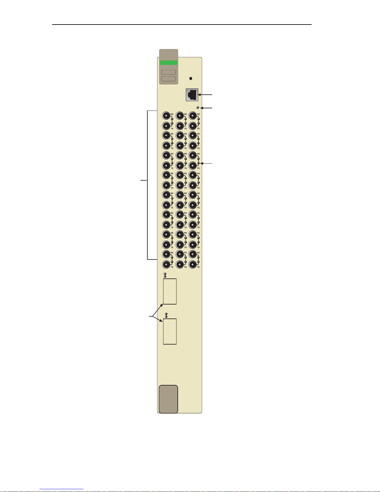
3.6.1 Connecting Fiber Optic Cables to
Ports 1 Through 24 of the Modules
Each fiber opti c link consists of two strands of fibe r optic cabling: the
transmit (TX) and the receive (RX). The transmit strand from a module
port connects to the receive port of a fiber optic Ethernet device at the
other end of the segment. The receive strand of the applicable port on the
module connects to the transmit por t of the fiber optic Ethernet device.
DIGITAL recom m en ds lab eling fiber optic cables to indicate receive and
transmit ends. Many cables are prelabeled, providing matching labels or
tapes at both ends of each strand of cable.
The instructions which fo llow detail the process used to connect an ST
connector to a module port.
1. Remove the protective pla stic covers from the fiber optic ports on the
applicable por t on th e module, and fr om the ends of the connectors o n
each fibe r stra nd.
Leave the protective rubber covers in place when the
connectors are not in use to prevent contamination.
Do not touch the ends of the fiber optic strands, and do not let
!
the ends come in contact with dust, dirt, or other contaminants.
Contamination of the ends causes problems in data
transmissions. If the ends become contaminated, blow the
surfaces with a canned duster. A fiber por t cleaning swab
saturated with optical-grade isoprop yl alcohol ma y also be used
to clean the ends.
2. Refer to Figure 3-2 and attac h one fiber to the applicable receive (RX)
port on the module. Insert the ST connector into the port with the
alignment slot on the connect or ins erted over the locking key on the
port. Turn the connector clockwise to lock it down.
3. Attach the other fiber of the pair to the applicable tra nsmit (TX) port
on the module. Use the same procedure for inse rtion of the ST
connector.
3-6 DLE28-MA User’s Guide

Connecting to the Network
4. At the other end of the fiber optic cable, attach the f iber pair to the
transmit and r eceive ports of the device.
.
Receive (RX) LED
17
231103
Figure 3-2 Fiber Optic Connection
5. Verify that a Link exists by checking that the port RX LED is on
(flashing amber , blinki ng green, or sol id gr een). If the RX LED is off,
perform the following steps until it is on:
a. Verify that the device at the other end of the segment is ON a nd
connected to the segment.
b. C heck the crossover of the cables. Swap the cable connections if
necessary.
c. Check the cable for continuity.
d. Check that the fibe r optic connection meets the dB loss and cable
specificati ons outlined in Chapter 2.
If a link is not established, contact your DIGITAL representative.
DLE28-MA User’s Guide 3-7

Chapter 3: Installation
6. Repeat steps 1 thr ough 5, above , unti l a ll c onnections ha ve bee n made.
3.6.2 Connecting a UTP Segment to the DELTX-UI
The DELTX-UI suppor ts Category 5 Unshielded Tw isted Pair
cable with an impedance between 85 and 111 ohms.
A DELTX-UI installed in por t 25 and/or 26 has an inte rnal crossover
switch. When c onnecting a workstation, use a straight-through cable and
set the Fast Eth ern et In te rface Mo dule crossover switch shown in
Figure 3-3 to the crossed over posi tion mar ked with X. When connecting
networking devices, such as another bridge, repeater, or router , use a
straight-through cable and set the Fast Ether net Interface Module
crossover switch shown in Figure 3-3 to the not crossed over position,
marked with =.
A schematic of a crossover cable is shown in Figure 3-3. If the wires do
not cross ove r, use the switch on the DELTX-UI to internally cross over
the RJ45 port. Figure 3-3 shows how to properly set the DELTX-UI
crossover switch.
Position =
(not crossed over)
1. TX+
2. TX-
3. RX+
4. NC
5. NC
6. RX-
7. NC
8. NC
=
DELTX-UI
x
Figure 3-3 DELTX-UI Crossover Switch
Position X
(crossed over)
1. RX+
2. RX-
10
100
3. TX+
4. NC
5. NC
6. TX-
7. NC
8. NC
LKG-10872-98F
Connect a DELTX-UI to a twisted pair segment as follows:
1. Ensure that the device connected to the other end of the segment is
powered ON.
2. Connect the twisted pair segment to the module by inserting the RJ45
connector on the twisted pai r segment into the RJ45 port on the
module shown in Figure 3-3.
3-8 DLE28-MA User’s Guide

Connecting to the Network
3. Verify that a link exists by checking that the port RX LED is on
(flashing amber , blinki ng green, or sol id gr een). If the RX LED is off,
perform the following steps until it is on:
a. V erif y that the 10 0BASE-TX de vice a t the other end of the twiste d
pair segment is powered up.
b. Verify that the RJ45 conne ctor on the twi sted pair se gment has the
proper pinouts.
c. Check the cable for continuity.
d. Make sure that the twisted pair connection meets dB loss and cable
specificati ons outlined in Section 2.3.
e. Confirm that the crossover switc h is in the correct position.
3.6.3 Connecting a Fiber Optic Segment
to the DELFX-UI and DELF3-UI
The DELFX-UI and DELF3-UI have an SC style net wor k port (see
Figure 3-4). DIGITAL supplies fiber optic cable that uses SC style
connectors whic h are keyed to ensure proper crossing over of the transmit
and receive fibers.
An odd number of crossovers (preferably one) must be
!
Fiber Optic Network Connection
maintained between devices so that the transmit port of one
device is connected to the receive por t of the other device and
vice versa .
If the fiber optic cable being used has SC style connectors that
do not resemble MIC style connectors, or has SC connectors
on one end and a diff erent type on the other , such as ST
connectors, ensure that the proper crossing ov er occurs.
1. Remove the protective pla stic covers from the fiber optic ports on the
applicable port on the module and fr om the ends of the conne ctors.
The DELF3-UI uses Class 1 lasers. Do not use optical
instruments to view the laser output. The use of optical
instruments to view laser output increases eye hazard. When
viewing the output optical port, power must be removed f rom
the network adapter.
DLE28-MA User’s Guide 3-9

Chapter 3: Installation
Do not touch the ends of the fiber optic strands, and do not let
!
the ends come in contact with dust, dirt, or other contaminants.
Contamination of the ends causes problems in data
transmissions. If the ends become contaminated, blow the
surfaces with a canned duster. A fiber port cleaning swab
saturated with optical-grade isoprop yl alcohol may also be used
to clean the ends.
2. Insert one end of the SC connector into the DELFX-UI or DELF3-UI
installed in the DLE28-MA. See Figure 3-4.
3. At the other end of the fiber optic cable, atta ch the SC connector to the
other device.
25
RX LED
TX LED
FE-100FX
26
Figure 3-4 DELFX-UI and DELF3-UI Port
4. Verify that a link exists by checking that the port RX LED is on
(flashing amber, blinking green , or solid green). If the RX LED is off
and the TX LED is not blinking amber, perf orm the following steps
until it is on:
3-10 DLE28-MA User’s Guide

Completing the Installation
The port RX LED flashes green and amber during bootup.
a. Check that the power is tur ned on for the de vice at the othe r end of
the link.
b. Verify proper crossing over of fiber strands between the
applicable por t on the DLE2 8-MA and the fiber optic de vice at t he
other end of the fiber optic link segment .
c. Verify that the fiber connec tion meets the dB loss specifications
outlined in Chapter 2.
3.7 COMPLETING THE INSTALLATION
The DLE28-MA is now ready to be set up through Local Manage ment.
Refer to Chapter 5, Local Management, to configure the modules and
DLM6C-AA chassis.
DLE28-MA User’s Guide 3-11


CHAPTER 4
TROUBLESHOOTING
This chapter prov ides information concerning the following:
• Using the LANVIEW diagnostic and status moni toring system
• Using the DELTX-UI LED
• Troubleshooting network and m odule operational problems
• Using the RESET button
The four interf ace modules covered in this manual all share the
same LANVIEW LEDs.
4.1 USING LANVIEW
The DLE28-MA uses the DIGITAL built- in visua l diagnostic and status
monitoring system calle d LANVIEW. The LANVIEW LEDs (Figure 4-1)
allow quick observation of the network status to aid in diagnosing
network problems. Refer to Table 4-1 for a description of the LEDs.
For a functional des cription of the LANVIEW LED on the optional Fast
Ethernet Interface Module (DELTX-UI), refer to Section 4.2.
All LEDs for the High Speed Int erface Module (HSIM) are located on the
HSIM and are described in the associated HSIM user’s guide.
The terms
definition tables of this chapter indicate the following:
Flashing
Blinking
Solid
indicates a steady LED light. No pulsing.
flashing, blinking
indicates an irregular LED pulse.
indicates a steady LED pulse (50% on, 50% off).
, and
solid
used in the LED
DLE28-MA User’s Guide 4-1

Chapter 4: Troubleshooting
Ethernet
DLE28-MA
CPU LED
COM
CPU
1917
2
10 18
31119
41220
51321
61422
71523
81624
25
26
Receive (RX)
Transmit (TX)
4-2 DLE28-MA User’s Guide
LKG-10783-98F
Figure 4-1 LANVIEW LEDs

Using LANVIEW
Table 4-1 LANVIEW LEDs
LED Color State Recommended Action
Off Power off. Power up chassis.
CPU
Blinking. Hardware
fai lure has occur red.
Red
Solid. Resetting,
normal power up res et.
Blinking. Crippled.
Amber
Solid. Testing.
Contact y our DIGITAL
represent ative.
No action. I f LED re mains Red
for several minutes, contact
your DIGITAL representati ve.
Contact y our DIGITAL
represent ative.
No action. If LED remains
Amber for several minutes,
contact y our DIGITAL
represent ativ e.
Green Solid. Functional. No action.
Amber
and
Green
Booting. Blinks amber
and green while
booting.
No action.
No link. No activity.
Off
Port enabled or
No error.
disabled.
RX
Solid. Port enabled,
link, no activity.
Green
Blinking. P ort
disabl ed, link.
Amber
Flashing. Port
enabled, link, activity.
Red Diagnostic failure.
No error.
No error.
No error.
Contact y our DIGITAL
representative for assistance.
DLE28-MA User’s Guide 4-3

Chapter 4: Troubleshooting
Table 4-1 LANVIEW LEDs (Continued)
LED Color State Recommended Action
1. Ensure that the STA is
enabled and that there is valid
link.
2. Contact your DIGITAL
representative for assistance
Off
Port enabled, and no
activity.
TX
Green
Amber
Red
Flashing
activity. Rate indicates
data rat e.
Blinking
standby, link.
Flashing
collis io n rat e.
Solid
Failure.
. Indic a te s
. Port in
. Indic a te s
. Diagnostic
No action.
1. Ensure that the port is not
disabled.
2. Contact your DIGITAL
representative for assistance
No action.
Contact y our DIGITAL
representative for assistance.
4.2 DELTX-UI LED
The optional DELTX-UI has one LED labeled 10/100. The 10/100 LED
together with the receive LED allows the user to determine th e link status
and the operating speed of the Fast Ethernet Interface Module. The
10/100 LED and the Receive (RX) LED are shown in Figure 4-2.
Table 4-2 and Table 4-3 provide a functional des cription of the
DELTX-UI LED when the RX LED is on or of f, respectively.
4-4 DLE28-MA User’s Guide

10
100
Receive
(RX) LED
LED
25 26
22
Figure 4-2 DELTX-UI LED
FE-100TX
100
10
DELTX-UI LED
=
x
A link exists if the associated port (port 25 or 26) Receive (RX)
LED is on.
Table 4-2 DELTX-UI LED Indicati ons Wh en the RX LED Is On
LED Color Descripti on
Off DELTX-UI is operating at 10 Mbps.
10/100
Green DELTX-UI is oper ating at 100 Mbps.
No link exists if t he associated port (port 25 or 26) Receive
(RX) LED is off.
Table 4-3 DELTX-UI LED Indications When the RX LED Is Off
LED Color Description
10/100
DLE28-MA User’s Guide 4-5
Off
Green
No link or no cable attached. DELTX-UI
forced to 10 Mbps operation, or is
manually set to “auto-negotiate” mode.
No link or no cable attached. DELTX-UI is
forced to 100 Mbps operation.

Chapter 4: Troubleshooting
4.3 TROUBLESHOOTING CHECKLIST
If the DLE28-MA or DLE3X-MA is not working properly, refer to
Table 4-4 for a checklist of possible problems, cause s, and recommended
actions to resolve the problem.
Table 4-4 T roubleshooting Checklist
Problem Possible Cause Recommended Action
All LEDs are OFF.
No Local
Management
Pa ssword screen.
Cannot contac t the
DLE28-MA from
in-band
management .
Loss of Power to the
DLM6C-AA chassis.
DLE28-MA not properly
instal led.
Autobaud enabled. But
baud rate has not yet
been sensed.
Terminal setup is not
correct.
Improper cons ole cable
pinouts .
Improper Community
Names T able.
DLE28-MA does not
have an IP address.
Port is disabled. Enable port.
Check the proper connection
of the power cable and its
access to a live outlet.
Check the i nstallation.
Press ENTER (RETURN)
(may take up to four times).
Refer to Chapter 5 for proper
setup procedures.
Refer to Appendix A for
proper console port pinouts.
Refer to Chapter 5
for Community Names Table
setup.
Refer to Chapter 5 for IP
address assignment
procedure.
No link to de vice. Check li nk to device.
Port(s ) goes into
standby for no
apparent re ason.
User p ar am ete rs (I P
address , Devi ce and
Module name , et c.)
were lost when the
DLE28-MA is
powered down or
the front panel
RESET button is
pressed.
DLE28-MA detects a
looped condition.
Mode sw itch (7), NVRAM
Reset, was changed
sometime before either
cycling power or
pressing the RESET
button, causing the
user-ent ered para meters
to reset to factory default
settings.
4-6 DLE28-MA User’s Guide
1. Review network design
and delete unnecessary
loops.
2. Contact your DIGITAL
representative for assistance
1. Reenter the lost
parame ters as necessary.
2. Contact your DIGITAL
representative for assistance

Using the RESET Button
4.4 USING THE RESET BUTTON
The RESET button located near the upper plastic locking tab of the
module (refer to Figure 4-3) res e ts the DLE28-MA processor without
affecting the NVRAM.
Pressing the RESET button resets the device, and all current
switching being performed by the device is halted. A module
downtime of up to two minutes will result from this action.
Ethernet
DLE28-MA
Reset Button
LKG-10983-98F
Figure 4-3 RESET Button
To reset the DLE28-MA processor, press and release the RESET button.
The module processor goes through a reset process of approximately 20
seconds. Additiona l modul e downtime may be added as the module
reenters the network.
DLE28-MA User’s Guide 4-7


CHAPTER 5
LOCAL MANAGEMENT
This chapter expl ains how to set up a management termina l to access
DLE28-MA Local Management. It also explains how to use the Local
Management scree n s and commands.
The Local Management screens shown in this chapter are for
the DLE28-MA. All Local Management functions specific to any
of the interface modules are preceded by a Note to alert the
reader.
5.1 OVERVIEW
Local Management f or the DLE28-MA consists of a series of
management screens that allow the management of the module, the
attached se gments a nd the DLM 6C-AA chassis. The management screens
allow the user to perf orm the following tasks:
• Manage any interface mo dule i n the chas sis via a connection to a
single interface module.
• Assign IP addresses and subnet masks to the DLE28-MA and the
DLM6C-AA chassis.
• Control access to the DLE28-MA and the DLM6C-AA chassis by
establishing communi ty names.
• Download a ne w image of operating software.
• Designate which Network Mana gement Workstations recei ve SNMP
traps from the DLE28-MA and the DLM6C-AA chassis.
• Monitor the environmental status of the DLM6C-AA chassis.
• View switch, inte rface, and RMON statistics.
• Assign ports to operate in standard or full duplex mode.
• Enable trunking of ports to perfor m load sharing.
• Configure the Fast Ethernet Inte rface Modules of the DLE28-MA.
There are thr ee ways to access Local Management:
DLE28-MA User’s Guide 5-1

Chapter 5: Loc al M anagem ent
• Locally using a VT type terminal connected to the C OM port of the
DLE28-MA.
• Remotely using a VT type terminal connected through a modem.
• In-band through a Telnet connection.
5.2 LOCAL MANAGEMENT KEYBOARD
CONVENTIONS
All key names appear as capital letters in this manual. Table 5-1 explains
the keyboard c onventions and the ke y functions that are used.
Table 5-1 Keyboard Conventions
Key Function
These are sel ection keys that perform the same
ENTER Key
RETURN Key
Local Managem ent function. For example, “Press
ENTER” means that y ou can press either ENTER
or RETURN, unless this ma nual specifi cally
instructs you otherwise.
ESCAPE (ESC) Ke y
SPACE bar
BACKSPACE Key
Arrow Keys
[–] K ey
DEL Key
This key allows an escape from a Local
Management screen without saving changes. For
example, “Press ESC twice” means the ESC key
must be pressed quick ly two times.
These k e ys cy cle t hrou gh selec tions in some Loc al
Management fi elds. Use the SPACE bar to cycl e
forward through selections and use BACKSPACE
to cycle backward through selections.
These are navigation keys. Use the UP-ARROW,
DOWN-ARROW, LEFT-ARROW, and
RIGHT-ARROW keys to move the screen cursor.
For example, “Use the arrow keys” means to press
whichever arrow k ey moves the cursor to the
desired field on the Local Management screen.
This key decreases values from a Local
Management increment field. For example, “Press
[–]” means to press the minus sign key.
The DEL (Delete ) key removes characters from a
Local Managem ent field. For example, “Press
DEL” means to press the Delete key.
5-2 DLE28-MA User’s Guide

Management Terminal Setup
5.3 MANAGEMENT TERMINAL SETUP
Use one of the followi ng systems to access Local Management:
• An IBM or compatible PC running a VT series emulation software
package
• A Digital Equipment Corporation VT100 type terminal
• A VT type terminal running emulation programs for the Digital
Equipment Corporation VT100 serie s
• A remote VT100 type terminal via a modem connection
• In-band via a Telnet connection
5.3.1 Console Cable Connection
Use the Console Cable Kit provide d with the DLM6C-AA chassis to
attach the m anagement terminal to the COM port as shown in Figure 5-1.
Connect an IBM PC or compatible device, running the VT terminal
emulation, to the DLE28-MA as follows:
1. Connect the RJ45 connector at one end of the cable (supplied in the
kit) to the COM port on the DLE28-MA.
2. Plug the RJ45 connector at the other end of the cable into the
RJ45-to-DB9 adapter (sup plied in the kit).
3. Connect the RJ45-to-DB9 adapter to the PC communications port.
Ethernet
DLE28-MA
COM
1917
2
10 18
CPU
RJ45 COM Port
TM
MultiSwitch 700
1
2345
Ethernet
DLE28-MA
25
26
COM
CPU PWR
1917
2
10 18
31119
41220
51321
61422
71523
81624
DLM6C-AA
PS1
PS2
TMTM
HA205-AAHA205-AA
PC
Figure 5-1 Management Terminal Connection
DLE28-MA User’s Guide 5-3
RJ45-to-DB9
PC Adapter
UTP Cable
With RJ45 Connectors
TM
H3105-AA
LKG-10784-98F

Chapter 5: Loc al M anagem ent
5.3.2 Connecting an Uninterruptible Power Supply
If the DLM6C-AA chassis is connected to an American Powe r
Conversion (APC) Uninterruptible Power Supply (UPS) for protection
from a loss of po wer, a connection from the COM port of a module to the
UPS can be made to monitor the power status of the UPS. To use the
COM port for this purpose, it must be reconfigured to support the UPS
application. This procedure is performed from the General C onfiguration
screen o f the int erfa ce module. Section 5.15.11, Configuring the COM
Port, provide s d etailed instructi ons on conf ig uring th e COM port fo r UPS
applications. Refer t o the UPS docum entat ion for de tails on ho w to acc ess
the status information.
Use the Console Cable Kit provide d with the DLM6C-AA chassis to
attach the UPS to the module COM port as shown in Figur e 5-2.
Connect the UPS device to the COM port of the DLE28-MA as follows:
1. Connect the RJ45 connector at one end of the cable to the COM port
on the DLE28-MA.
2. Plug the RJ45 connector at the other end of the cable into the
RJ45-to-DB9 male (UPS) adapter , Cable tron Part No. 9372066.
3. Connect the RJ45-to-DB9 male (UPS) ada pter to the female DB9 port
on the rear of the UPS device (refer to the particular UPS device’s user
instructions fo r more specific information about the monitoring
connection).
Ethernet
DLE28-MA
TMTM
COM
CPU
1917
2
10 18
RJ45 COM Port
DB9 Port
TM
MultiSwitch 700
1
2345
DLE28-MA
25
26
Ethernet
COM
1917
2
31119
41220
51321
61422
71523
81624
DLM6C-AA
PS1
PS2
CPU
10 18
HA205-AAHA205-AA
TM
H3105-AA
UPS Device
RJ45-to-DB9
UPS Adapter
Figure 5-2 Uninterru pti ble Power Supply (UPS)
5-4 DLE28-MA User’s Guide
UTP Cable
with RJ45 Connectors
LKG-10785-98F

Management Terminal Setup
5.3.3 Management Terminal Setup Parameters
Table 5-2 lists the setup parameters for the local management termina l.
Table 5-2 VT Termi nal Se t up
Displa y Setup Menu
Columns ->
Contro ls ->
Auto Wrap ->
Scroll ->
Text Cursor ->
Cursor Style ->
General Setup Menu
Mode ->
ID number ->
Curs o r Keys ->
Power Supply ->
Communic ati ons Setup Menu
Transmit ->
Receiv e ->
XOFF ->
Bits ->
Parity ->
Stop Bit ->
Local Echo ->
Port ->
Transmit ->
Auto Answerback ->
80 Columns
Interpret Controls
No Auto Wrap
Jump Scroll
Cursor
Underline Cursor Style
VT100, 7 Bit Controls
VT100ID
Normal Cursor Keys
UPSS DEC Supplemental
2400, 4800, 9600, 19200
Receive=Transmit
XOFF at 64
8 bits
No Parity
1 Stop Bit
No Local Echo
DEC-423, Data Leads Only
Limited Transmit
No Auto Answerback
Keyboard Setup Menu
Keys ->
Auto Repeat ->
Keyclick ->
Margin Bell ->
Warning Bell ->
DLE28-MA User’s Guide 5-5
Typewriter Keys
any option
any option
Margin Bell
Warning Bell

Chapter 5: Loc al M anagem ent
5.3.4 Telnet Connections
Once the module or chassis has a v alid I P address, the user can establis h a
Telnet session with Local Management from any TCP/IP based node on
the network. Telnet connections to the DLE28-MA require the
community name passwords assigned at the SNMP Community Names
screen of either the DLM6C-AA chassis, or the module. F or additional
information about community names, refer to Section 5.8, SNMP
Community Names Screen. Refer to the instructions included with the
Telnet application for information about establishing a Telnet session.
5-6 DLE28-MA User’s Guide

Accessing Local Management
5.4 ACCESSING LOCAL M ANAGEMENT
Access to Local Management is contro lled through the Passwor d screen,
Figure 5-3. Whenever a connection is made to the DLE28-MA the
Password screen displays. Before continuing, the user must enter a
password which is compared to the previously stored passwords. The
level of access allo wed the user depends on the password. To set or
change passwords refer to Section 5.8. The following step s de s crib e the
procedure to access Local Management.
1. Turn on the terminal. Press ENTER (this may take up to four tim es,
because the COM port of the DLE28-MA aut o-sens es the ba ud rate o f
the terminal) until the DLM6C-AA Local Management Password
screen, Figure 5-3, displays.
Event Message Line
Figure 5-3 Local Management P assword Screen
MS 700 Local Management
Enter Password:
Digital Equipment Corporation
(c) Copyright CABLETRON Systems, Inc, 1998
LKG-10808-98F
2. Enter the Password and press ENTER. The default Super-Us er acces s
password is “public” or press ENTER.
DLE28-MA User’s Guide 5-7

Chapter 5: Loc al M anagem ent
The User’s pass word is one of the community names specified
in the SNMP Community Names screen. Access to certain
Local Manageme nt capabilities depends on the degree of
access accorded that community name. Refer to Section 5.8.
If an invalid password is entered, the terminal beeps and the
cursor returns to the beginning of the password entry field.
Entering a valid password causes the associated access level
to display at the bottom of the screen and the Main Menu
screen to display.
If no activity occurs for several minutes, the Password s cre en
displays and the session ends.
5.4.1 Navigating Local Management Screens
The DLE28-MA Local Management application consists of a series of
menu screens. Na viga te through Local Management by selecting items
from the menu screens.
The DLE28-MA support two modes of switch operat ion. The switching
modes are as follo ws:
• 802.1D Switching, (IEEE 802. 1D switc hing)
• 802.1Q Switching, (IEEE 802.1Q port based VLANs)
Refer to the Release Notes shipped with the product to verify
which screens are supported in each of the two available
switc h ing mode s.
The switch operational mode may be set in either the Chassis
Configuration screen (Section 5.7), or the General Co n figuration screen
of the module (Section 5.15). Depending on the Operational Mode set for
the module, the hierarchy of Local Management screens differs as shown
in Figure 5-4, and Figure 5-5. Refer to the appropriate figure that relate s
to the Operational Mode that will be set fo r the modul e to see the
applicab l e Lo cal Ma na gement screen hierarchy.
5-8 DLE28-MA User’s Guide

\
Password
Chassis
Menu
Accessing Local Management
General Configuration
SNMP Community Names
SNMP Traps
Chassis Environmental
Port Redirect Function
Module
Configuration
Menu
Main
Menu
General Configuration
SNMP Community Names
SNMP Traps
Switch Configuration
Ethernet Full Duplex
Configuration
Module
Menu
Module
Statistics
Menu
SmartTrunk Configuration
Module Specific
Configuration
Switch Statistics
Interface Statistics
RMON Statistics
System
Resources
High Speed
Interface
Configuration
Flash Download
Port Redirect
Function
Broadcast
Suppression
Network Tools
Figure 5-4 802.1D Switching Mode, LM Screen Hierarchy
Chassis
Menu
General Configuration
SNMP Community Names
SNMP Traps
Chassis Environmental
Fast
Ethernet
HSIM
231169
Password
Main
Menu
Module
Menu
Module
Configuration
Menu
Module
Statistics
Menu
Network Tools
General Configuration
SNMP Community Names
SNMP Traps
Switch Configuration
Ethernet Full Duplex
Configuration
SmartTrunk Configuration
Module Specific
Configuration
Switch Statistics
Interface Statistics
RMON Statistics
System
Resources
High Speed
Interface
Configuration
Flash Download
Broadcast
Suppression
802.1Q VLAN
Configuration
Fi g ure 5- 5 802.1Q Sw itching Mo de, L M Sc reen H ierarchy
Fast
Ethernet
HSIM
231170
DLE28-MA User’s Guide 5-9

Chapter 5: Loc al M anagem ent
5.4.2 Selecting Local Management Menu Screen Items
Select items on a menu screen by performing the following steps:
1. Use the arrow keys to highlight a menu item.
2. Press ENTER. The selected menu item displays on the screen.
5.4.3 Exiting Local Management Screens
There are two ways to exit Local Management (LM).
Using the EXIT Command
To exit an LM screen using the EXIT command, proceed as follows:
1. Use the arrow keys to highlight the EXIT command at the bottom of
the Local Man a ge me n t scree n .
2. Press ENTER. The Password screen displays and the session ends.
Using the RETURN Command
To exit an LM screen using the RETURN command, proceed as follows:
1. Use the arrow keys to highli ght the RETURN command at the b ottom
of the Local Management screen.
2. Press ENTER. The previous screen in the Loca l Man agement
hierarchy displays.
The user can also exit Local Management screens by pressing
ESC twice. This exit method does not warn about unsaved
changes and all unsaved changes will be lost.
3. Exit from DLE28-MA Local Management by repeating steps 1 and 2
until the Main Menu screen displays.
4. To end the session, use the arrow keys to highlight the RETURN
command at the bottom of the Main Menu screen.
5. Press ENTER. The Password screen displays and the session ends.
5-10 DLE28-MA User’s Guide

The Mai n Menu Screen
5.5 THE MAIN MENU SCREEN
The Main Menu scr een is the ac cess point for all Local Management
screens for the module and th e DLM6C-AA cha ssis. F igure 5-6 shows t he
Main Menu screen.
DLE28-MA User’s Guide 5-11

Chapter 5: Loc al M anagem ent
MS 700 LOCAL MANAGEMENT
Main Menu
CHASSIS
MODULES
EXIT
RETURN
LKG-10809-98F
Figure 5-6 Main Menu Screen
If the terminal is idle for several minutes, the Local
Managemen t Password sc reen displays and the session ends.
The following explains each Main Menu screen ite m as shown in
Figure 5-6:
5-12 DLE28-MA User’s Guide

The Mai n Menu Screen
CHASSIS
The Chassis menu item provide s access to the Chassis Menu screen,
shown in Figure 5-7, that is used to conf igure the DLM6C-AA chassis,
access current chassis power supply and environmental status, and to
configure IEEE 802.1Q VLANs.
Access the Chassis Configuration screen by using the arrow ke ys to
highlight the CHASSIS menu item and pressing ENTER. The C hassis
Configuration screen displays. Proceed to Section 5.6.
MODULES
The Modules menu item provides access to the Module Selection screen
that is used to select individual modules in the chassis for management
purposes.
Access the Module Selection screen by using the arrow keys to highlight
the MODULES menu item and pressing ENTER. The Module Selection
screen displays. Proceed to Section 5.12.
DLE28-MA User’s Guide 5-13

Chapter 5: Loc al M anagem ent
5.6 CHASSIS MENU SCREEN
The Chassis Menu screen, Figure 5-7, provide s access to Local
Management scree n s tha t allow you to configure and monitor operating
parameters, modify SNMP community names, set SNMP traps, monitor
the DLM6C-AA environmental status, perform port redirec t functions,
and to configure the DLM6C-AA for IEEE 802.1Q operation.
MS 700 LOCAL MANAGEMENT
Chassis Menu
CHASSIS CONFIGURATION
SNMP COMMUNITY NAMES
SNMP TRAPS
CHASSIS ENVIRONMENTAL
PORT REDIRECT FUNCTION
EXIT
RETURN
LKG-10810-98F
Figure 5-7 Chassis Menu Screen
The following briefly explains each screen access ible from the Chassis
Menu screen.
CHASSIS CONFIGURATION
The Chassis Configuration screen allows the user to configure operating
parameters for the DLM6C-AA chassis. For details, refer to Section 5.7.
SNMP COMMUNITY NAMES
The SNMP Community Names screen allows the user to enter new,
change, or r eview the community names used as access passwords for
device management operation. Access is limited based on the password
level of the user. For details, refer to Section 5.8.
5-14 DLE28-MA User’s Guide

Chassis Menu Screen
SNMP TRAPS
The SNM P Traps screen provides display and configuration access to the
table of IP addresses used for trap destinati ons and associated community
names. For details, refer to Section 5.9.
CHASSIS ENVIRONMENTAL
The Chassis Environmental screen provides access to chassis power
supply status, power supply redundancy status and chassis fan tray stat us.
For details, ref er to Section 5.10.
PORT REDIRECT FUNCTION
The Port Redirect Function screen allows the user to redi rec t traffic from
one or multiple modules and ports in the chassis to a specific destination
module or port. For details, refer to Section 5.11.
DLE28-MA User’s Guide 5-15

Chapter 5: Loc al M anagem ent
5.7 CHASSIS CONFIGURATION SCREEN
The Chassis Config uration screen, Figure 5-8, allows the user to set the
chassis date and time, IP address and Subnet Mask, the operational mode
of all modules installed in the chassis, the screen refresh and lockout
times, and to view the chassis uptime.
Access the Chassis Configuration screen fro m the Ch assis Menu screen
by using the arrow keys to highlight the CHASSIS CONFIGURATION
menu item and pressing ENTER. The Chassis Configuration screen,
Figure 5-8, displays.
Event Message Line
MAC Address:
IP Address:
Subnet Mask:
Operational Mode: [802.1D SWITCHING]
Figure 5-8 Chassis Configuration Screen
MS 700 LOCAL MANAGEMENT
Chassis Configuration
00-00-ID-00-00-00
000.000.000.000
000.000.000.000
EXIT
Chassis Date:
Chassis Time:
Screen Refresh Time:
Screen Lockout Time:
Chassis Uptime XX D XX H XX M
10/11/97
14:23:00
30 sec.
15 min.
RETURNSAVE
LKG-10811-98F
The following briefly explains each Chassis Configuration screen field:
MAC Address
(Read-Only)
Displays the ba se physical address of the chassis.
5-16 DLE28-MA User’s Guide

Chassis Configuration Screen
IP Address (Modifiable)
This field allows the IP address to be set for the DLM6C-AA chassis. If
an IP addre s s is assign e d to th e DLM 6 C- A A cha s sis all the interface
modules installed in the chassis can be managed via this IP address,
eliminating the need to assi gn an IP address to e ach interface module. To
set the IP address, refer to Section 5.7.1.
Subnet Mask (Modifiable)
When a valid IP address is assigned, the Subnet Mask field
automatically enters the default mask that corresponds with
class of IP entered in the IP Address field. Some firmware
revisions do support changing the chass is subnet mas k from
the default va lue. Refer to your Re lease Not es to ensure that
the Subnet Mask is a modifiable field.
Displays the subnet mask for the chassis. A subnet mask “masks out” the
network bits of the IP a ddress by setting t he bi ts in the mas k to 1 when the
network treats the corresponding bits in the IP addre ss as par t of the
network or subnetwor k address, or to 0 if the corresponding bit identifies
the host. The DLM6C-AA chassis automatically uses the default subnet
mask that corresponds to the IP class tha t was entered in the IP address
field. S ection 5.7.2, Setting the S ubnet Mask describes how to change the
subnet mask from the default value.
Chassis Date (Modifiable)
Contains a value that the chassis recognizes as the current date. When the
chassis date is modified and saved all interface modules installed in the
chassis are set to this date. To set a new chassis date, refer to
Section 5.7.3.
Chassis Time (Modifiable)
Contains a value that the chassis recognizes as the current time. When the
chassis time is modified and saved, all interface modules installed in the
chassis are set to this time. To enter a new time, refer to Section 5.7.4.
Screen Refresh Time (Modifiable)
Contains the rate at which the scree ns are updated. This setting
determines ho w frequently (in seconds) information is updated on the
screen. To enter a new update time, r efer to Section 5.7.5.
DLE28-MA User’s Guide 5-17

Chapter 5: Loc al M anagem ent
Scre en Lockout Time (Modifiable)
Contains the maximum number of minutes that the Local Management
application displays a module’s screen wh ile awaiting input or action
from a user. For example, if the number 5 is entered in this field, the use r
has up to five minutes to res pond to each of the specified module’s Local
Management screens. In this e xample , afte r f i v e minutes of “idlene ss” ( no
input or action), the terminal “beeps” five times, the Local Management
application t erminates the se ssion, a nd the d isplay r eturns to the P assw ord
screen. To enter a new lockout time, refer to Section 5.7.6.
Chassis Uptime (Read-Only)
Displays the total time the chassi s has been operat ing. The chassi s uptime
is based on which interface module installed in the chassis has been
operating for the longest period of time.
Operation a l Mo de (Toggle)
This field a llo ws the user to set all the modules in the chassi s to operate a s
traditional switches (802.1D SWITCHING option), or as IEEE 802.1Q
switches (802.1Q SWITCHING option).
In 802.1D SWITCHING mode, the 24 ports located on the front panel,
and each Fast Ethernet Interface Module, and HSIM port( s) a re bridged t o
each other.
When the operational mode is set to 802.1Q SWITCHING, the
DLE28-MA acts as IEEE 802.1Q switches. The modules are able to
increase their switching functionality by c reating and maintaining port
based Virtual LANs (VLANs).
For details on how to select the Operational Mode, refer to Sect ion 5.7 .7 .
5.7.1 Setting the IP Address
To set the IP address, perform the following steps:
1. Use the arrow keys to highlight the IP Address field.
2. Enter the IP address into this field using Decimal Dotted Notation
(DDN) format.
For example: 134.141.79.120
5-18 DLE28-MA User’s Guide

Chassis Configuration Screen
3. Press ENTER. If the IP address is a valid for mat, the cursor re tur ns to
the beginning of the IP addre ss field. I f the entry is n ot valid , the Event
Message Line displays “INVALID IP ADDRESS OR FORMAT
ENTERED”. Local Management does not alter the current value and
refreshes the IP address field with the previous value.
4. Use the arrow keys to highlight the SAVE command, then press
ENTER. The “SAVED OK” message displays indicating that the
changes have been saved to memory.
5.7.2 Setting the Subnet Mask
If the management worksta tion that is to receive SNMP traps from the
DLM6C-AA is located on a separate subnet, the subnet mask for the
DLM6C-AA must be changed from its default.
When a valid IP address is assigned, the Subnet Mask field
automatically enters the default mask that corresponds with
class of IP entered in the IP Address field. Some firmware
revisions do support changing the chass is subnet mas k from
the default va lue. Refer to your Re lease Not es to ensure that
the Subnet Mask is a modifiable field.
To change the subnet mask from its default, perform the following steps:
1. Use the arrow keys to highlight the Subn et Ma s k fiel d .
2. Enter the subnet mask into this field using Decimal Dotted Notation
(DDN) format.
For example: 255.255.255.0
3. Press ENTER. If the subnet mask is valid, the cursor returns to the
beginning of the Subnet Mask field. If the entr y is n ot valid , the Ev ent
Message Line displays “INVALID SUBNET MASK OR FORMAT
ENTERED”. Local M anagement does not alter the current value, but
it does refresh the Subnet Mask field with the previous value.
4. Use the arrow keys to highlight the SAVE command, then press
ENTER. The changes are saved to memory.
DLE28-MA User’s Guide 5-19

Chapter 5: Loc al M anagem ent
5.7.3 Setting the Chassis Date
The DLM6C-AA is year 2000 compliant, so the Chassis Date may be set
beyond the year 1999. To set the chassis date, pe rfor m the following
steps:
1. Use the arrow keys to highlight the Chassis Date field.
2. Enter the date in this format: MM/DD/YYYY
It is not necessar y to add separators between month, day, and
year numbers. F or example, to set the date to 03/17/1997, type
“03171997” in the Chassis Date field.
3. Press ENTER to set the system calendar to the date in the input field.
4. Use the arrow keys to hig hlight the SAVE command at the bottom of
the scree n and pres s ENTER.
If the date entered is a va lid format, the Event Message Line at the top of
the scree n displays “SAVED OK”. If the entry is not valid, Local
Management does not alter the current value, but it does refresh the
Chassis Date field with the previous value.
Upon saving the new chassis date, all interface modules
installed in the chassis recognize the new value as the current
date.
5.7.4 Setting the Chassis Time
To set the chassis clock, perform the following steps:
1. Use the arrow keys to highlight the Chassis Time field.
2. Enter the time in a 24-hour format: HH:MM:SS
When enterin g the time in the system time field, separators
between hours, minutes, and seconds do not need to be added
as long as each entry uses two numeric characters. F or
A.M
example, to set the time to 6:45
Chassis Time field.
., type “064500” in the
3. Press ENTER to set the system clock to the time in the input field.
5-20 DLE28-MA User’s Guide

Chassis Configuration Screen
4. Use the arrow keys to hi ghlight the SAVE command at the bottom of
the screen and press ENTER.
If the time entered is a valid format , the Event Message Line at the top of
the screen displays “SAVED OK”. If the entry is not valid, Local
Management does not alter the current value and refreshes the Chassis
Time field with the previous value.
Upon saving the new chassis time, all interface modules
installed in the chassis recognize the new value as the current
time.
5.7.5 Entering a New Screen Refresh Time
The screen refresh time is set from 3 to 99 seconds with a default of 3
seconds. To set a new screen refr esh time, perform the following steps:
1. Use the arrow keys to highlight the Scre en Refresh Time fi el d.
2. En t er a num b er from 3 to 99.
3. Press ENTER to set the refresh time to the time entered in the input
field.
4. Use the arrow keys to hi ghlight the SAVE command at the bottom of
the screen and press ENTER.
If the time entered is within the 3 to 99 se conds range, the Event Message
Line at the top of the screen displays “SAVED OK”. If the entry is not
valid, Local Management does not alter the current setting, but it does
refresh the Screen Refresh Time field with the previous value.
5.7.6 Setting the Screen Lockout Time
The scree n lockout time can be set from 1 to 30 minutes with a default of
15 minutes. To set a new lockout time, perform the following steps:
1. Use the arrow keys to highlight the Scre en Lockout Time field .
2. En t er a num b er from 1 to 30.
3. Press ENTER to set the lockout time in the input field.
4. Use the arrow keys to hi ghlight the SAVE command at the bottom of
the screen and press ENTER.
DLE28-MA User’s Guide 5-21

Chapter 5: Loc al M anagem ent
If the time entered is within the 1 to 30 mi nutes range, the Event Message
Line at the top of the screen displays “SAVED OK”. If the entry is not
valid, Local Management does not alter the current setting, but it does
refresh the Screen Lockout Tim e field with the previous v a lue.
5.7.7 Setting the Operational Mode
To set the Operational Mode, proceed as follows:
1. Use arrow keys to highlight the Operat ion al M o de field.
2. Press the SPACE bar to step to the appropriate oper ation mode,
(802.1D SWITCHING or 802.1Q SWITCHING).
3. Use the arrow keys to hi ghlight the SAVE command at the bottom of
the screen and pr ess ENTER. The war ning screen shown in Figure 5-9
displays:
WARNING!
YOU HAVE ELECTED TO SAVE THE OPERATIONAL MODE FOR
THE WHOLE CHASSIS. THIS WILL CAUSE ALL OF THE
BOARDS IN THE CHASSIS TO REBOOT.
ARE YOU SURE YOU WANT TO SAVE THE NEW OPERATIONAL MODE?
NOYES
1666
Figure 5-9 Operational Mode W arning Screen
4. Use the arrow keys to highlight the YES command and press ENTER.
The changes are saved, and all the modules ins talled in the chassis
reboot.
5-22 DLE28-MA User’s Guide

Chassis Configuration Screen
If the DLE28-MA have been set to 802.1Q SWITCHING, refer
to your
P ort Based VLAN U ser’s Guide
to configure the devices
for this type of operation.
DLE28-MA User’s Guide 5-23

Chapter 5: Loc al M anagem ent
5.8 SNMP COMMUNITY NAMES SCREEN
The SNMP Community Na mes menu item allows the user to set Local
Management community names. Community names act as passwords to
Local/Remote Management and provide security a ccess to the
DLM6C-AA. Access to the DLM6C-AA is controlled by enacting any of
three different levels of security authorization ( rea d-only, read-write, and
super-user).
Super-User access gives the user full management privileges,
allows existing passwords to be changed, and all modifiable
MIB objects for t he DIGITAL Container MIB and Internet MIB-II
to be edited .
Access the SNMP Community Names screen from the Chassis Menu
screen by using the arrow keys to highlight the SNMP COMMUNITY
NAMES menu item and pressing ENTER. The SNMP Community
Names screen, Figure 5-10, displa ys.
Event Message Line
MS 700 LOCAL MANAGEMENT
SNMP Community Names
Community Name
public
public
public
EXIT
Access Policy
read-only
read-write
super-user
RETURNSAVE
LKG-10812-98F
Figure 5-10 SNMP Community Names Scr een
5-24 DLE28-MA User’s Guide

SNMP Community Names Screen
The following explains each SNMP Community Names screen field:
Community Name (Modifiable)
Displays the user-d efined na me through which a user accesses
DLM6C-AA management. Any community name assigned he re acts as a
password to Local/Remote Management.
Access Policy (Read-Only)
Indicates the access accorded each community name. Possible selections
are as follows:
read-only This community name allows read-only acce ss
to the DLM6C-AA MIB objects, and excludes
access to se curity-pr otected f ields of read-write
or super-user authorization.
read-write This community name allows read and write
access to the DLM6C-AA MIB objects,
excluding security protect ed fields for
super-user access only.
super-user This community name permits read-write
access to the DLM6C-AA MIB objects and
allows the user to change all modifiable
parameters including community names, IP
addresses, tr aps, and SNMP objects.
5.8.1 Establishing Community Names
The password used to ac cess Local Management at the Password screen
must have Super-User access in or der to view and edit the SNMP
Community Names screen. Using a password with read-only or
read-write access does not allow the user to view or edit the SNMP
Community Names screen.
Any community name assigned in the SNMP Community
Names screen is a password to its corresponding level of
access to Local Management . The community nam e assigned
Super-User access is the only one that gives the user complete
access to Local Management .
DLE28-MA User’s Guide 5-25

Chapter 5: Loc al M anagem ent
All passwords assigned in the DLM6C-AA SNMP Community
Names screen allow access to both DLM6C-AA Local
Managemen t screens, and the Local Management screens of
the interface modules that are installed in the chassis. To
configure the interface module to not allow access to
DLM6C-AA Local Management screens refer to Section 5.16.
To establish community names, proceed as follows:
1. Use the arrow keys to highlight the Community Name field adjacent
to the selected access level.
2. Enter the password in the field (maximum 31 characters).
3. Press ENTER.
4. Repeat steps 1 through 3 to modify the other community names.
5. Use the arrow keys to high light SAVE at the bott om of t he scre en and
press ENTER. The message “SAVED OK” displays. The community
names are saved to memory and their access modes implemented.
5-26 DLE28-MA User’s Guide

SNMP T r aps Screen
5.9 SNMP TRAPS SCREEN
Since the DLM6C-AA is an SNMP compliant device , it c an send
messages to multiple Networ k Management Stations to alert users of
status changes. The SNMP Traps screen is shown in Figure 5-11.
Access the SN M P Traps scree n from the Chassis Menu screen by using
the arrow keys to highlight the SNMP TRAPS menu item and pressing
ENTER. The SNMP Traps scree n displa ys.
Event Message Line
MS 700 LOCAL MANAGEMENT
Chassis SNMP Traps
Trap Destination
0.0.0.0
0.0.0.0
0.0.0.0
0.0.0.0
0.0.0.0
0.0.0.0
0.0.0.0
0.0.0.0
Trap Community Name
public
public
public
public
public
public
public
public
EXIT
Enable Traps
[YES]
[YES]
[YES]
[YES]
[YES]
[YES]
[YES]
[YES]
RETURNSAVE
Figure 5-1 1 SNMP Traps Screen
The following explains each f ield of the SNMP Traps screen.
LKG-10813-98F
Trap Destination
Indicates the IP address of the workstation to receive trap alarms. Up to
eight different destinat ions can be defined.
Trap Community Name
Displays the Community Name included in the trap message sent to the
Network Management Station with the associate d IP addres s.
DLE28-MA User’s Guide 5-27
(Modifiable)
(Modifiable)

Chapter 5: Loc al M anagem ent
Enable Traps (Toggle)
Enables transmiss ion of the traps to the network mana gement sta tion with
the associated IP address. This field toggles between YES and NO.
5.9.1 Configuring the Trap Table
To configure the Trap table, proceed as follows:
1. Using the arrow keys, highlight the appropriate Trap Destination
field.
2. Enter the IP Address of the workstation that is to receive traps. IP
address entries must follow the DDN format.
For example: 134.141.79.121
3. Press ENTER. If an invalid entry is entered “INVALID IP
ENTERED” is displayed in the Event Message Line.
4. Using the arrow keys, highlight the Trap Community Name field.
Enter the community name.
5. Press ENTER.
6. Using the arrow keys, highlight the Enable Traps field. Press the
SPACE bar to choose eithe r YES (send alarms fr om the chassis t o the
workstation), or NO (prevent alarms from being sent).
7. Using the arrow keys, highlight the SAVE command and press
ENTER. The message “SAVED OK” displays on the screen.
Exiting without saving causes a “NOT SAVED?” message to
appear above the SAVE command. Edits will be lost if they are
not saved before exiting.
The designated workst ations now receive traps from the DLM6C-AA.
5-28 DLE28-MA User’s Guide

Chassis Environmental Screen
5.10 CHASSIS ENVIRONMENTAL SCREEN
The Chassis Environmental menu item allows the user to view chassis
environmental information.
To access the Chassis Environmental Infor mation s creen from the Chassis
Menu screen, use the arrow keys to highlight the CHASSIS
ENVIRONMENTAL menu item and press ENTER. The Chassis
Environmental Information screen, Figure 5-12, displays.
MS 700 LOCAL MANAGEMENT
Chassis Environmental Information
Chassis Power Redundancy
Power Supply #1 Status
Power Supply #2 Status
Chassis Fan Status
EXIT
Not Available
Normal
Not Installed
Normal
RETURN
LKG-10814-98F
Figure 5-12 Chassis Environmental Information Screen
The following describes each of the Chassis Environmental Information
screen fields.
Chassis Power Redundancy
(Read-Only)
Displays the c urrent redundancy sta tus of the DLM6C-AA power
supplies. This field will read either “Available” or “Not Available”.
Pow er Supply #X Status
Displays the curr ent st atus of powe r suppli es 1 an d 2 for the DLM6C-AA.
This field will read either “Normal”, “Fault”, or “Not Insta lled”.
Chassis Fan Status
Displays the c urrent status of the DLM6C-AA fan tray. This field will
read either “Normal”, “Fa ult”, or “Not Installed”.
DLE28-MA User’s Guide 5-29
(Read-Only)
(Read-Only)

Chapter 5: Loc al M anagem ent
5.11 PORT REDIRECT FUNCTION SCREEN
The Port Redirect Function screen may not be ava ilable
depending on the operational mode that has been set for the
chassis. Refer t o your Release Notes to see what operational
modes support the Por t Redirect Function. Refer to
Section 5.7.7,
on configuring the operational mode of all t he modules installed
in the chassis.
Setting the Operational Mode
The Port Redirect Function screen, Figure 5-13, allows the user t o set
each one of the modules in the cha ssis (1 through 5), and the ports of the
corresponding module insta lled, as a source or destina tion port. A port
can be set to have one or more destination ports and chassis module slot
numbers. For example, port 1 in module (slot) 1 can be set as a source
port with three destinations, ports 2, 3, and 4 in module (slot) 3. Traffic
from port 1 in module 1 is then automatically redirected to ports 2, 3, and
4 in module 3. Port 1 in module 1 can also serve as a destinati on port for
other ports and mod ules. The port r edire ct f unction is e xtre mely useful f or
troubleshooting purposes, as it a llows traffic to be sent to a particula r
port(s) where, with the use of an analyzer or RMON probe, all current
, for instructions
traffic from the source port(s) can be examined.
The module number corresponds to the slot number in which
the module resides in the DLM6C-AA chassis (1 through 5).
Although traffic from the source port (including, if desired,
errored frames) is sent to the destination port, normal switching
is still performed for all frames on the source port.
Access the Port Redirect Funct ion screen from the Chassis Menu screen
by using the arrow keys to highlight the PORT REDIRECT
FUNCTION menu item and pressing ENTER. The Port Redirect
Function screen, Figure 5-13, displa ys.
5-30 DLE28-MA User’s Guide

Event Message Line
Module
1
1
1
2
2
3
3
3
Port Redirect Function Screen
MS 700 LOCAL MANAGEMENT
Port Redirect Function
Source Destination Remap Errors
============ ============ ============
Port
1
1
1
2
2
3
3
3
Module
3
3
3
1
3
4
5
5
Port
2
3
4
1
3
4
5
8
ON
ON
ON
OFF
ON
ON
ON
OFF
Status [ADD]
Errors [ON]
RETURN
RETURN
LKG-10815-98F
SAVE
Source Port [1]
Source Module [1]
EXIT
Destination Port [1]
Destination Module [1]
NEXT
PREVIOUS
Figure 5-13 Port Redirect Funct ion Screen
The following definitions briefly explain e ach field of the Port Redirect
Function screen.
Source Module
(Read-Only)
Displays which m odules are currently set as source modules.
Source Port
(Read-Only)
Displays which ports are curr ently set as source ports.
Destin a t ion Mo dule
(Read-Only)
Displays which m odules are currently set as destination modules.
Destin a t ion Port
(Read-Only)
Displays which ports are curr ently set as destination port s.
Remap Errors
(Read-only)
Displays whether the corresponding source modules and ports are
configur ed to send err ored fr ames to the des tinati on modules and por ts, or
to drop all err o red frames before forw arding traffic.
Source Module [n]
Allows a selecte d module [n] to be configured as a source module.
DLE28-MA User’s Guide 5-31
(Selectable)

Chapter 5: Loc al M anagem ent
Source Port [n] (Selectable)
Allows a selecte d port [n] to be configured as a source port.
Destin a t ion Mo dule [n] (Selectable)
Allows a selecte d module [n] to be configured as a desti nation module.
Destination Port [n] (Selectable)
Allows a selecte d port [n] to be configured as a destination port.
Errors (Toggle)
Allows the user to configure the source modules and ports to either send
errored frames to selected destination modules and ports ( ON option), or
to drop errored frames, and send only valid traffi c to the dest ination
modules and ports (OFF option). The default setting of this field is ON.
Status (Toggle)
Allows the user to add or delete the source/ des tination modules and ports
selected in the Source/ Destination Modules and ports fields.
5.11.1 Displaying the Source and Destination Entries
There can be more than one Port Redirect Function screen depending on
the number of port redirect entries. Each screen displa ys up to ten port
redirect entri es. If there is more than one screen of redirect entries, the
NEXT and/or PREVIOUS command is displ ayed at the bottom of the
screen, allowing the user to navigate to the next or previous screen.
To display the next screen, use the arrow keys to highlight NEXT. Pres s
ENTER and the next screen of entri es is dis played.
To display the previ ous screen, use the arrow keys to highlight
PREVIOUS. Press ENTER to view the entries in the previous screen.
5-32 DLE28-MA User’s Guide

Port Redirect Function Screen
5.11.2 Changing Source and Destination Ports
Add or delete source/destination module and port entr ies as follows:
1. Use the arrow keys to highlight the Sour ce Module fiel d.
2. Press the SPACE bar or BACKSPACE one or more times to incr ement
or decrement the module number dis played in the bracke ts [n] un til the
appropriate module number is displayed.
3. Use the arrow keys to highlight the Source Port field.
4. Press the SPACE bar or BACKSPACE one or more times to incr ement
or decrement the port num ber displayed in the brackets [n] until the
appropriate port number is displayed.
5. Use the arrow keys to highlight the Destination Module field.
6. Use the SPACE bar or BACKSPACE to step to the appropriate
module number for the destination module.
7. Use the arrow keys to highlight the Destination Port field.
8. Use the SPACE bar or BACKSPACE to step to the appropriate port
number for the destination port.
9. Use the arrow keys to highlight the Status fi el d.
10. Use the SPACE bar to se lect either the ADD or DEL (delete) option.
Press ENTER. This adds or deletes the select ions made in steps 2 and
4 and also updates t he screen Source M odule, Source Port, De stination
Module and Destination Port lists.
11. Use the arrow keys to highlight the Errors fi el d.
12. Use the SPACE bar to select either the ON or OFF option and pr ess
ENTER. ON forces the source module and port to forward errored
frames to the destination mod ule(s) and port(s). OFF forces th e
errored frames to be dr opped before forwarding traffic.
If more than one module and port is to be redirected, repeat
steps 1 through 12 for each additional setting, then go to step
13 to save all the new settings at once.
13. Use the arrow keys to highlight SAVE at the bottom of the screen.
Press ENTER. The message “SAVED OK” is displayed.
DLE28-MA User’s Guide 5-33

Chapter 5: Loc al M anagem ent
F
5.12 MODULE SELECTION SCREEN
The Module Selecti on screen is the access point to Loca l Manage ment for
all modules installe d in the DIGITAL MultiSwitch 700 chassis. By
selecting a module, the Module Menu for the sele cted device displays.
Figure 5-14 shows the Module Selection sc reen.
Event Message Line
MS 700 LOCAL MANAGEMENT
Module Selection
Module #
<1>
2
3
4
5
Module Type
DLE28-MA
DLE32-MA
DLE23-MA
DLE22-MA
Serial #
123456789
123456789
123456789
123456789
EXIT
Hardware Revision
XXX
XXX
XXX
XXX
RETURN
LKG-10816-98
Figure 5-14 Module Selection Screen
The following explains each Module Sele ction screen field as sho wn in
Figure 5-14.
Module #
The Module # field displays the slot in which the module is installed. The
module number enclose d in < > characters indicates the module to which
the management terminal or Telnet session is connected.
Module Type
The Module Type field displays the type of interface module that is
installed in each slot.
5-34 DLE28-MA User’s Guide

Module Selec tion Screen
Serial #
Indicates the seria l number of the module. The se rial num ber of the d e vic e
is necessary when calling your DIGITAL representative.
Hardware Revision
Reflects the hardwa re version of the module.
5.12.1 Selecting a Module
To select an individual module to perform Local Management functions,
proceed as follows:
1. Use the arrow keys to highlight the desired module number in the
Module # field.
2. Press ENTER, the applicable Module Menu screen displays. P roceed
to Section 5.13.
DLE28-MA User’s Guide 5-35

Chapter 5: Loc al M anagem ent
5.13 MODULE MENU SCREEN
The Local Management screens shown in this chapter are for
the DLE28-MA. All Local Management functions specific to any
interface module are preceded by a note to aler t the reader.
The DLE28-MA Module Menu screens are the access point for all Local
Management scree n s for the DLE28-MA. Figure 5-15 shows the
DLE28-MA Module Menu screen.
MS 700 LOCAL MANAGEMENT
Module Menu
Module Type: DLE28-MA
Slot Number: X
Firmware Revision: XX.XX.XX
BOOTPROM Revision: XX.XX.XX
MODULE CONFIGURATION
MODULE STATISTICS
NETWORK TOOLS
EXIT
Figure 5-15 Module Menu Screen
RETURN
LKG-10817-98F
5-36 DLE28-MA User’s Guide

Module Menu Screen
The following explains each Module Menu screen field as shown in
Figure 5-15:
MODULE CONFIGURATION
The Module Configura tion screen provides access to the Local
Management scree n s tha t are used to co nfigure the DLE28-MA. The
Module Specific Configuration Menu screen provides access to the
screens that allow the user to check DLE28-MA resources and set
operating parameters specific to each port. For details about the Module
Configur at ion Menu screen , refe r to S ec tio n 5.14. For deta ils ab o ut the
Module Specific Configuration M enu screen, refer to Section 5.21.
MODULE STATISTICS
The Module Statistics screen provides statistics and performance
information for the DLE28-MA. For details about this screen, refe r to
Section 5.27.
NETWORK TO OLS
The Network Tools function resides on the DLE28-MA and consists of a
series of commands that allow the user to access and manage networ k
devices. Section 5.31 explains how to use the Network Tools utility.
DLE28-MA User’s Guide 5-37

Chapter 5: Loc al M anagem ent
5.14 MODULE CONFIGURATION MENU SCREEN
The Module Configuration Menu screen, Figure 5-16, provides access to
Local Management sc reens that allow you to configure and monitor
operating parameters, modif y SNMP community names, set SNMP traps,
configure switch parameters and configure DLE28-MA ports.
To access the Module Configura tion Menu scree n from the Module Menu
screen, use the arrow keys to highlight the MODULE
CONFIGURATION menu item and press ENTER. The Module
Configuration screen displays.
MS 700 LOCAL MANAGEMENT
Module Configuration Menu
Module Type: DLE28-MA
Slot Number: X
Firmware Revision: XX.XX.XX
BOOTPROM Revision: XX.XX.XX
GENERAL CONFIGURATION
SNMP COMMUNITY NAMES
SNMP TRAPS
SWITCH CONFIGURATION
ETHERNET FULL DUPLEX CONFIGURATION
SMARTTRUNK CONFIGURATION
MODULE SPECIFIC CONFIGURATION
RETURNEXIT
LKG-10818-98F
Figure 5-16 Module Configurati on M enu Screen
The following briefly explains each screen access ible from the Module
Configuration Menu screen:
GENERAL CONFIGURATION
The General Configuration screen allows the user to monitor and
configure operating pa rameters for the DLE28-MA. For details, refer to
Section 5.15.
5-38 DLE28-MA User’s Guide

Module Configuration Menu Screen
SNMP COMMUNITY NAMES
The SNMP Community Names screen allows the user to enter new,
change, or r eview the community names used as access passwords for
Local/Remote management opera tion. Access is limite d based on the
password level of the user. For details, refer to Section 5.16.
SNMP TRAPS
The SNM P Traps screen provides display and configuration access to the
table of IP addresses used for trap destinati ons and associated community
names. For details, refer to Section 5.17.
SWITCH CONFIGURATION
The Switch Configura tion screen provides basic setup options for
modifying the switching fu nctions of the modules. For det ai ls, refer to
Section 5.18.
ETHERNET FULL DUPLEX CONFIGURATION
The Ethernet Full Duplex Configuration scre en allows each 10 Mbps port
(1 to 24) to be set for either Standard Ethernet or Full Duplex operat ion.
The screen also indicates whether or not each port is linked to another
Ethernet device and if that port is enable d. F or details, refer to
Section 5.19.
SMARTTRUNK CONFIGURATION
The SmartT runk Configuration screen allows the user to logically gr oup
interfaces together to create wider bandwidth uplinks. F or details, refer to
Section 5.20.
MODULE SPECI FIC CONFI GURATION
The Module Specific Configura tion Menu screen allows the user to
configur e ports or che ck system resourc es speci f ic to th e DLE28-MA. F or
details , refe r to Sec tio n 5.2 1.
DLE28-MA User’s Guide 5-39

Chapter 5: Loc al M anagem ent
Firmware Revision: XX.XX.XX
General Configuration
LKG-10819-98F
BOOTPROM Revision: XX.XX.XX
MAC Address:
IP Address:
Subnet Mask:
Default Gateway:
TFTP Gateway IP Addr:
Module Date:
Module Time:
Screen Refresh Time:
Screen Lockout Time:
Com: [ENABLED] Application: [LM]
Clear NVRAM [NO]
Module Uptime XX D XX H XX M
Module Type: DLE28-MA
Slot Number: X
IP Fragmentation [ENABLED]
Operational Mode: [802.1D SWITCHING] Management Mode: [DISTRIBUTED]
00-00-ID-00-00-00
0.0.0.0
255.255.0.0
NONE DEFINED
0.0.0.0
MS 700 LOCAL MANAGEMENT
Event Message Line
RETURNSAVE
10/11/97
14:23:00
30 sec.
15 min.
EXIT
5.15 GENERAL CONFIGURATION SCREEN
The General Configuration screen, Figure 5-17, allows the user to set the
system date and time, I P address and subne t mask, the default gateway,
the TFTP gateway IP address, the operational mode, the management
mode, set the screen refresh and lockout times, and the COM port
configuration. The General Configuration screen also allows the user to
Clear NV RAM, and enabl e or disable IP Fragmentation .
To access the General Configuration screen from the Module
Configuration Menu screen, use the arrow keys to highlight the
GENERAL CONFIGURATION menu item and press ENTER. The
General Co nfiguration screen, Figure 5-17, displays.
The following briefly explains each General Configuration screen field:
MAC Address
Displays the ba se physical address of the module.
5-40 DLE28-MA User’s Guide
Figure 5-17 General Confi guration Screen
(Read-Only)

General Configuration Screen
The IP Address can also be set through Runtime IP Address
Discovery as previously described in Section 1.1.8.
IP Address (Modifiable)
This display allows the user to set the IP address f or the DLE28- MA. To
set the IP address, refer to Section 5.15.1.
Subnet Mask (Modifiable)
Displays the subnet mask for the module. A subne t mask “masks out” t he
network bits of the IP a ddress by setting t he bi ts in the mas k to 1 when the
network treats the corresponding bits in the IP addre ss as par t of the
network or subnetwor k address, or to 0 if the corresponding bit identifies
the host. When an IP address is entered in th e IP Add ress f ield, the Subnet
Mask field automatically enters the default subnet mask for the IP
address. For de tails about how to change the subnet mask from its default
value, refer to Se ction 5 .15 .2.
Defau lt Gateway (Modifiable)
Displays the default gateway for the DLE28-MA. This fie ld is not def ine d
until an appropriate value is entered. For details about why a nd how to set
the Defaul t Gat eway, refer to Section 5.15.3.
TFTP Gateway IP Addr (Modifiable)
Displays and allo ws the user to set the TFTP Gateway IP address for the
DLE28-MA. To set the TFTP Gate way IP address, refer to Section 5.15.4.
Module Date (Modifiable)
Contains a value tha t the module recognizes as the curr ent date. To set a
new module date, refer to Section 5.15.5.
Module Time (Modifiable)
Contains a value that the module re cogniz es as the cur rent ti me. To enter a
new time, refer t o Sect ion 5.1 5.6 .
DLE28-MA User’s Guide 5-41

Chapter 5: Loc al M anagem ent
Screen Refresh Time (Modifiable)
Contains the rate at which the screens are updated. This setting
determines how frequently (in seconds) information is updated on the
screen. To enter a new update time, refer to Section5.15.7.
Screen Lockout Time (Modifiable)
Contains the maximum number of minutes that the Local Management
application displays a module’s screen while awaiting input or action
from a user. For example, if the number 5 is entered in this field, the user
has up to five minutes to respond to each of the specified module’s Local
Management screens. In this example, after five minutes of “idleness” (no
input or action), the terminal “beeps” five times, the Local Management
application terminates the session, and the display returns to the Password
screen. To enter a new lockout time, refer to Section5.15.8.
Module Uptime (Read-Only)
Displays the total time that the module has been operating.
Operational Mode (Selectable)
This field allows the user to set the DLE28-MA to operate as an IEEE
802.1D switch (802.1D SWITCHING option), or an IEEE 802.1Q switch
(802.1Q SWITCHING option).
In 802.1D SWITCHING mode, the 24 ports located on the front panel,
and each Fast Ethernet Interface Module, and HSIM port(s) are bridged to
each other.
In 802.1Q SWITCHING mode, the DLE28-MA are able to increase their
switching functionality by creating and maintaining IEEE port based
VLANs.
For details on how to select the Operational Mode, refer to Section5.15.9.
Management Mode (Toggle)
This field toggles between DISTRIBUTED and STAND ALONE.
In DISTRIBUTED mode, Local Management is entered via the
DLM6C-AA password screen, and all chassis configuration screens are
available to the user. All other modules installed in the chassis that are set
for distributed management may also be accessed via a connection to a
single COM port on one of the modules.
5-42 DLE28-MA User’s Guide
 Loading...