

Digital Equipment DIGITAL Ultimate Workstation 533, AlphaServer 1200 Service Manual

AlphaServer 1200
DIGITAL Ultimate Workstation 533
Service Manual PRELIMINARY
Order Number: EK–1200A–SV. A01
This manual is for anyone who services an
AlphaServer/AlphaStation system. It includes troubleshooting
information, configuration rules, and instructions for removal and
replacement of field-replaceable units.
Digital Equipment Corporation
Maynard, Massachusetts

First Printing, November 1997
Digital Equipment Corporation makes no representations that the use of its products in the
manner describ e d in th is pu b lic atio n will not infringe o n ex istin g o r fu tu re p a ten t rig h ts, nor do
the descriptions contained in this publication im ply the granting of licens es to make, use, or
sell equipment or software in accordance with the description.
The information in this document is subject to change without notice and should not be
construed a s a c o mmitme nt b y Digital Equ ip me n t C o rp o ra tio n .
Digital Equipment Corpor ation assumes no responsibility for any errors that may appear in
this documen t.
The software, if any, described in this document is furnis hed under a license and m ay be used
or copied only in accordance with the term s of such license. No responsibility is assumed for
the use or reliability of software or equipment that is not supplied by Digital Equipment
Corporatio n o r its affilia te d co mp a n ies .
Copyright 1997 by Digital Equipment Corporation. All rights reserved.
The following are trademarks of Digital Equipment Corporation: AlphaGeneration,
AlphaSe rver, Ope nVMS, Stor ageWor ks, VAX, the Al phaGener ation l ogo, and the DIGITAL
logo.
The following are third-party trademarks: Lifestyle 28.8 DATA/FAX Modem is a trademark
of Motorola, Inc. UNIX is a registered tradem ark in the U.S. and other countries, licensed
exclusively through X/Open Company Ltd. U.S. Robotics and Sportster are registered
trademarks of U.S. Robotics. Windows NT is a trademark of Microsoft, Inc. All other
trademarks and registered trademarks are the property of their respective holders.
FCC Notice : The equipment described in this manual generates, uses, and may emit radio
frequency energy. The equipment has been type tested and found to comply wit h t he limits for
a Class A digital device pursuant to Part 15 of FCC Rules, which are designed to provide
reasonable protection against such radio frequency interference. Operation of t his equipment
in a residential area may cause interference, in which case the user at his own expense will be
required to take whatever measures are required to correct the interference.
Shielded Cables: If shi el ded cabl es have been s uppl i ed or s pecif i ed, they mus t be used on the
system in order to ma in tain in tern a tio n al re g u lato ry co mp lia n ce .
Warning! This is a Class A product. In a domestic envir onment thi s product m ay cause radio
interference, in which case the user may be required to take adequate measures.
Achtung! Dies es ist ein Gerät der Funkstörgrenzwertklasse A. In Wohnbereichen können bei
Betrieb dieses Gerätes Rundfunkstörungen auftreten, in welchen Fällen der Benutzer für
entsprechen d e G e g en ma ß n ah me n v e ran twortlich ist.
Avertissement! Cet appareil est un apparei l de Classe A. Dans un environnement r ésidenti el,
cet appareil peut provoquer des brouillages radioélectriques. Dans ce cas, il peut être demandé
à l'utilisateur de p ren d re les mes u res ap p ro p rié es .

Contents
Preface
…………………………………………………………….………………x
Chapter 1 Overview
1.1 1200 System ............................................................................................1-2
1.2 Control Panel and Drives .........................................................................1-4
1.3 System Consoles......................................................................................1-6
1.4 System Architecture.................................................................................1-8
1.5 CPU Types............................................................................................1-10
1.6 Memory.................................................................................................1-12
1.7 Memory Addressing...............................................................................1-14
1.8 System Motherboard.............................................................................. 1-16
1.8.1 System Bus (Backplane) .................................................................1-18
1.8.2 System Bus to PCI Bus Bridge........................................................1-20
1.8.3 PCI I/O Subsystem..........................................................................1-22
1.8.4 Rem ot e Cont rol Logi c.....................................................................1-24
1.8.5 Power Control L ogi c.......................................................................1-26
1.9 Power Circuit and Cover Interloc k.........................................................1-28
1.10 Power Supply.........................................................................................1-30
1.11 Power Up/Down Sequence.....................................................................1-32
1.12 Maintenance Bus (I
1.13 StorageWorks ........................................................................................1-36
2
C Bus)....................................................................1-34
Chapter 2 Power-Up
2.1 Control Panel...........................................................................................2-2
2.2 Power-Up Sequence.................................................................................2-4
2.3 SROM Power-Up Test Flow ....................................................................2-8
2.4 SROM Errors Reported .......................................................................... 2-11
2.5 XSROM Power-Up Test Flow................................................................2-12
2.6 XSROM Errors Reported....................................................................... 2-15
2.7 Console Power-Up Tests........................................................................2-16
2.8 Console Device Determination ..............................................................2-18
2.9 Console Power-Up Display.................................................................... 2-20
2.10 Fail-Safe Loader....................................................................................2-24
Chapter 3 Troubleshooting
3.1 Troubleshooting with LEDs .....................................................................3-2
iii

3.2 Troubleshooting Power Problems............................................................. 3-4
3.3 Running Diagnostics — Test Command..................................................3-6
3.4 Releasing Secure Mode............................................................................3-7
3.5 Testing an Entire System.........................................................................3-8
3.5.1 Testing Memory..............................................................................3-10
3.5.2 Testing PCI .....................................................................................3-12
3.6 Other Useful Console Commands.......................................................... 3-14
Chapter 4 Error Logs
4.1 Using Error Logs .....................................................................................4-2
4.1.1 Hard Errors .......................................................................................4-4
4.1.2 Soft Errors ........................................................................................4-4
4.1.3 Error L og E vent s ............................................................................... 4-5
4.2 Using DECevent......................................................................................4-6
4.2.1 Translating Event Files..................................................................... 4-7
4.2.2 Filtering Events.................................................................................4-8
4.2.3 Selecting Alternative Reports .......................................................... 4-10
4.3 Error Log Examples and Analysis.......................................................... 4-11
4.3.1 MCHK 670 CPU-Detected Failure..................................................4-11
4.3.2 MCHK 670 CPU and IOD-Detected Failure....................................4-16
4.3.3 MCHK 670 Read Dirty CPU-Detected Failure................................4-21
4.3.4 MCHK 660 IOD-Detected Failure (System Bus Error)....................4-27
4.3.5 MCHK 660 IOD-Detected Failure (PCI Error)................................4-32
4.3.6 MCHK 630 Correctable CPU Error.................................................4-41
4.3.7 MCHK 620 Correctable Error .........................................................4-44
4.4 Troubleshooting IOD-Detected Errors....................................................4-47
4.4.1 System Bus ECC Error.................................................................... 4-48
4.4.2 System Bus Nonexistent Address Error...........................................4-49
4.4.3 System Bus Address Parity Error ....................................................4-50
4.4.4 PIO Buffer Ove rfl ow E rror (PIO_OVFL ) ........................................4-51
4.4.5 Page Table Entry Invalid Error........................................................4-52
4.4.6 PCI Master Abort............................................................................4-52
4.4.7 PCI System Error............................................................................4-52
4.4.8 PCI Parity E rror ..............................................................................4-52
4.4.9 Broken Mem ory..............................................................................4-53
4.4.10 Command Codes.............................................................................4-55
4.4.11 Node IDs.........................................................................................4-56
4.5 Double Error Halts and Machine Checks While in PAL Mode ............... 4-57
4.5.1 PALcode Overview.........................................................................4-57
4.5.2 Double E rror Hal t ...........................................................................4-58
4.5.3 Machine Checks While in PAL.......................................................4-58
iv

Chapter 5 Error Registers
5.1 External Interface Status Register - EL_STAT.........................................5-2
5.1.1 External Interface Address Register - EI_ADDR...............................5-6
5.1.2 MC Error Information Register 0 (MC_ERR0 - Offset = 800)..........5-8
5.1.3 MC Error Information Register 1 (MC_ERR1 - Offset = 840)..........5-9
5.1.1 CAP Error Registe r (CAP_ERR - Offset = 880) .............................5-11
5.1.2 PCI Error Status Register 1 (PCI_ERR1 - Offset = 1040)................5-14
Chapter 6 Removal and Replacement
6.1 System Safety ..........................................................................................6-1
6.2 FRU List..................................................................................................6-2
6.3 System Exposure .....................................................................................6-6
6.4 CPU Removal and Replacement..............................................................6-8
6.5 CPU Fan Removal and Replacement .....................................................6-10
6.6 Memory Riser Card Removal and Replacement.....................................6-12
6.7 DIMM Removal and Replacement.........................................................6-14
6.8 System Motherboard (54-25147-01) Removal and Replacement............6-16
6.9 PCI/EISA Option Removal and Replacement........................................6-18
6.10 Power Supply Removal and Replacement..............................................6-20
6.11 Power Harness Removal and Replacement.............................................6-22
6.12 System Fan Removal and Replacement..................................................6-24
6.13 Cover Interlock Removal and Replacement...........................................6-26
6.14 Operator Control Panel Removal and Replacement................................6-28
6.15 CD-ROM Removal and Replacement ....................................................6-30
6.16 Floppy Removal and Replacement......................................................... 6-32
6.17 SCSI Disk Removal and Replacement...................................................6-34
6.18 StorageWorks Backplane Removal and Replacement ............................6-36
6.19 StorageWorks Repeater Removal and Replacement...............................6-38
Appendix A Running Utilities
A.1 Running Utilities from a Graphics Monitor............................................. A-2
A.2 Running Utilities from a Serial Terminal................................................ A-3
A.3 Running ECU ......................................................................................... A-4
A.4 Updating Firmware with LFU ................................................................. A-5
A.4.1 Updating Firmware from the Inte rna l CD-ROM ...................................... A-7
A.4.2 Updating Firmware from the Internal Floppy Disk — Creating the
Disketts................................................................................................ A-11
A.4.3 Updating Firmware from the Inte rna l Floppy Disk — Performi ng t he
Update................................................................................................. A-13
A.4.4 Updating Firmware from a Network Device..........................................A-17
A.4.5 LFU Commands................................................................................... A-21
v

A.5 Updating Firmware from AlphaBIOS.................................................... A-24
A.6 Upgrading AlphaBIOS.......................................................................... A-25
A.7 Hard Disk Partitioning.......................................................................... A-26
A.7.1 Hard Disk Error Conditions .................................................................. A-26
A.7.2 System Partitions.................................................................................. A-27
A.7.3 How AlphaBIOS Works with System Partitions.................................... A-28
A.8 Using the Halt Button...........................................................................A-29
A.9 Halt Assertion....................................................................................... A-30
Appendix B SRM Console Commands and
Environment Variables
B.1 Summary of SRM Console Commands .................................................. B-2
B.1.1 Summary of SRM Environment Variables.............................................. B-4
B.2 Recording Environment Vari a ble s .......................................................... B-6
Appendix C Running Utilities
C.1 RCM Overview....................................................................................... C-2
C.2 First-Time Setup..................................................................................... C-3
C.2.1 Configuri ng t he Modem.......................................................................... C-4
C.2.2 Dialing In and Invoking RCM................................................................. C-5
C.2.3 Using RCM Locally................................................................................ C-6
C.3 RCM Commands.................................................................................... C-7
C.4 Dial-Out Alerts..................................................................................... C-16
C.5 Using the RCM Switchpack.................................................................. C-19
C.6 Troubleshooting Guide ........................................................................ C-23
C.7 Modem Dialog Details.......................................................................... C-26
Index
Examples
2–1 SROM Errors Reported at Power-Up ...........................................................2-11
2–1 XSROM Errors Reported at Power-Up........................................................2-15
2–1 Power-Up Display.......................................................................................2-20
3–1 Test Command Syntax..................................................................................3-6
3–1 Releasing/Reestablishing Secure Mode...........................................................3-7
3–1 Sample Test Command...................................................................................3-8
3–1 Sample Test Memory Command.................................................................3-10
3–1 Sample Test Command for PCI...................................................................3-12
3–1 Show Power...............................................................................................3-14
3–2 Show Memory ............................................................................................3-14
3–3 Show FRU.................................................................................................3-15
4–1 MCHK 670.................................................................................................4-12
vi

4–1 MCHK 670 CPU and IOD-Detected Failure ...............................................4-17
4–1 MCHK 670 Read Dirty Failure...................................................................4-22
4–1 MCHK 660 IOD-Detected Failure (System Bus Error)................................4-28
4–1 MCHK 660 IOD-Detected Failure (PCI Error)............................................ 4-33
4–1 MCHK 630 Correctable CPU Error.............................................................4-42
4–1 MCHK 620 Correctable Error..................................................................... 4-45
4–1 INFO 3 Command ......................................................................................4-59
4–2 INFO 5 Command ......................................................................................4-61
4–3 INFO 8 Command ......................................................................................4-63
6–1 Starting LFU from the SRM Console...........................................................A-5
6–2 Booting LFU from the CD-ROM.................................................................A-6
6–1 Updating Firmware from the Internal CD-ROM...........................................A-7
6–1 Creating Update Diskettes on an OpenVMS System ..................................A-12
6–1 Updating Firmware from the Internal Floppy Disk..................................... A-13
6–2 Selecting AS1200FW to Update Firmware from the Internal Floppy Disk .. A-16
6–1 Updating Firmware from a Network Device .............................................. A-17
6–1 Sample Remote Dial-In Dialog .................................................................... C-5
6–1 Invoking and Leaving RCM Locally............................................................ C-6
6–1 Configuring the Modem for Dial-Out Alerts.............................................. C-16
6–2 Typical RCM Dial-Out Command............................................................. C-17
Figures
1-1 1200 System...................................................................................................1-2
1-2 Cover Interlock Circuit..................................................................................1-3
1-3 Control Panel Assem bl y ................................................................................1-4
1-4 Architecture Diagram....................................................................................1-8
1-5 CPU Module Placement..............................................................................1-10
1-6 Memory Placement .....................................................................................1-12
1-7 How Memory Addressing Is Calculated.......................................................1-14
1-8 System Motherboard .....................................................................................1-16
1-9 System Bus Block Diagram......................................................................... 1-18
1-10 System bus to PCI bus Bridge Block Diagram...........................................1-20
1-11 PCI Block Diagram ...................................................................................1-22
1-12 Remote Control Logic ...............................................................................1-24
1-13 Power Control Logic ................................................................................. 1-26
1-14 Power Circuit Diagram................................................................................ 1-28
1-15 Back of Power Supply and Location..........................................................1-30
1-16 Power Up/Down Sequence Flowchart.........................................................1-32
2
1-17 I
1-18 StorageWorks Drive Location ....................................................................1-36
2-1 Control Panel and LCD Display .................................................................... 2-2
2-2 Power-Up Flow............................................................................................. 2-4
2-3 Contents of FEPROMs..................................................................................2-5
C Bus Block Diagram..............................................................................1-34
vii

2-4 Console Code Critical Path (1200 Block Diagram)........................................2-6
2-5 SROM Power-Up Test Flow......................................................................... 2-8
2-6 XSROM Power-Up Flowchart.....................................................................2-12
2-7 Console Device Determination Flowchart ...................................................2-18
3-1 System Motherboard LEDs............................................................................3-2
4-1 Error Detector Placement..............................................................................4-2
6-1 System FRU Locations..................................................................................6-2
6-2 Exposing the System .....................................................................................6-6
6-3 Removing CPU Module ................................................................................6-8
6-4 Removing CPU Fan.....................................................................................6-10
6-5 Removing Memory Riser Card....................................................................6-12
6-6 Removing A DIMM from a Memory Riser Card .......................................... 6-14
6-7 Removing System Motherboard ..................................................................6-16
6-8 Removing PCI/EISA Option........................................................................ 6-18
6-9 Removing Power Supply .............................................................................6-20
6-10 Removing Power Harness..........................................................................6-22
6-11 Removing System Fan...............................................................................6-24
6-12 Removing Cover Interlocks .......................................................................6-26
6-13 Removing OCP ......................................................................................... 6-28
6-14 Removing CD_ROM.................................................................................6-30
6-15 Removing Floppy...................................................................................... 6-32
6-16 Removing StorageWorks Disk...................................................................6-34
6-17 Removing StorageWorks Backpla ne..........................................................6-36
6-18 Removing StorageWorks Repeater............................................................6-38
A-1 Running a Utility from a Graphics Monitor................................................. A-2
A-2 Starting LFU from the AlphaBIOS Console................................................. A-5
A-3 AlphaBIOS Setup Screen........................................................................... A-24
A-1 System Partition Not Defined.................................................................... A-28
C-1 RCM Connections ....................................................................................... C-3
C-2 Location of RCM Switchpack on System Board........................................ C-19
C-3 RCM Switches (Factory Settings).............................................................. C-20
TablesI
1-1 PCI Motherboard Slot Numbering ................................................................1-23
2-1 Control Panel Display....................................................................................2-3
2-2 SROM Tests................................................................................................2-10
2-3 XSROM Tests............................................................................................. 2-13
2-4 Memory Tests ............................................................................................. 2-14
2-5 IOD Tests....................................................................................................2-16
2-6 PCI Motherboard Tests................................................................................ 2-17
4-1 Types of Error Log Events ............................................................................4-5
4-2 DECevent Report Formats...........................................................................4-10
4-3 CAP Error Register Data Pattern................................................................. 4-47
viii

4-4 System Bus ECC Error Data Pattern............................................................4-48
4-5 System Bus Nonexistent Address Error Troubleshooting.............................4-49
4-6 Address Parity Error Troubleshooting .......................................................... 4-50
4-7 Cause of PIO_OVFL Error ..........................................................................4-51
4-8 ECC Syndrome Bits Table........................................................................... 4-54
4-9 Decoding Commands ..................................................................................4-55
4-10 Node IDs................................................................................................... 4-56
5-1 External Interface Status Register..................................................................5-4
5-2 Loading and Locking Rules for External Interface Registers.........................5-7
5-3 MC Error Information Register 0...................................................................5-8
5-4 MC Error Information Register 1.................................................................5-10
5-5 CAP Error Register ..................................................................................... 5-12
5-6 PCI Error Status Register 1..........................................................................5-14
6-1 Field-Replaceable Unit Part Numbers............................................................ 6-3
A-1 AlphaBIOS Option Key Mapping................................................................A-3
A-1 File Locations for Creating Update Diskettes on a PC ............................... A-11
A-2 LFU Command Summary.......................................................................... A-21
B-1 Summary of SRM Console Commands........................................................ B-2
B-2 Environment Variable Summary.................................................................. B-4
B-3 Environment Variable s Workshee t............................................................... B-6
C-1 RCM Command Summary........................................................................... C-7
C-2 RCM Status Command Fields.................................................................... C-15
C-3 Elements of the Dial-Out String................................................................. C-18
C-4 RCM Troubleshooting ............................................................................... C-23
ix

Preface
Intended Audience
This manual is written for the customer service engineer.
Document Structure
This manual uses a structured documentation design. Topics are organized into
small sections for efficient online and printed reference. Each topic begins with an
abastract, followed by an illustration or example, and ends with descriptive text.
This manual has six chapters and three appendixes, as follows:
• Chapter 1, System Overview, introduces the DIGITAL AlphaServer 1200
pedestal and cabinet systems and gives an overview of the system bus modules.
• Chapter 2, Power-Up, provides information on how to interpret the power-up
display on the operator control panel, the console screen, and system LEDs. It
also describes how hardware diagnostics execute when the system is initialized.
• Chapter 3, Troubleshooting, describes troubleshooting during power-up a nd
booting, as well as the test command.
• Chapter 4, Error Logs, explains how to interpret error logs and how to use
DECevent.
• Chapter 5, Error Registers, describes the error registers used to hold error
information.
• Chapter 6, Removal and Replacement, describes removal and replacement
procedures for field-replaceable units (FRUs).
• Appendix A, Runni ng Ut ilities, explains how to run utilities such as the EISA
Configuration Utility and RAID Standalone Configuration Utility.
• Appendix B, SRM Consol e Commands and Envi r onme nt Var i a bl e s,
summarizes the commands used to examine and alter the system configuration.
• Appendix C, Oper ati ng the Syste m Re mote l y , describes how to use the remote
console monitor (RCM) to monitor and control the system remotely.
x

Documentation Titles
Table 1 lists books in AlphaServer 1200 documentation set.
Table 1 AlphaServer 1200 Documentation
Title Order Number
User and Installation Documentation Kit QZ–011AA–GZ
AlphaServer 1200 User’s Guide EK–AS120–UG
AlphaServer1200 Basic Installati on Guide EK–AS120–IG
Service Information
AlphaServer 1200 Service Manual EK–AS1200–SV
xi


Chapter 1
System Overview
This chapter introduce s the DIGITAL AlphaServer 1200 a nd t he DIGITAL
AlphaStation 1200 systems. These systems are available in cabinets or pedestals.
Pedestal systems contain a maximum of two CPUs, up to 2 Gbyte s of m em ory, a nd 6
PCI I/O slots or 5 PCI I/O slots and 1 EISA/ISA slot. A single StorageWorks shelf
provides disk storage.
Topics in this chapter include the following:
• 1200 Systems
• Control Panel and Drives
• System Consoles
• System Architecture
• CPU Types
• Memory Modules
• Memory Addressing
• System Motherboard
• System Bus Backplane
• System Bus to PCI Bus Bridge
• PCI I/O Subsystem
• Remote Control Monitor
• Power Control Logic
• Power Circuit and Cover Interloc k
• Power Supply
• Power Up/Down Sequence
2
• Maintenance Bus (I
• StorageWorks Drives
C Bus)
System Overview 1- 1
1.1 1200 System
The 1200 system has up to two CPU modules and 2Gbytes of memory. A single
fast wide SCSI Sto rageWorks shelf pr ovides storage. The system is r eady for
the next generatio n o f SCSI drives.
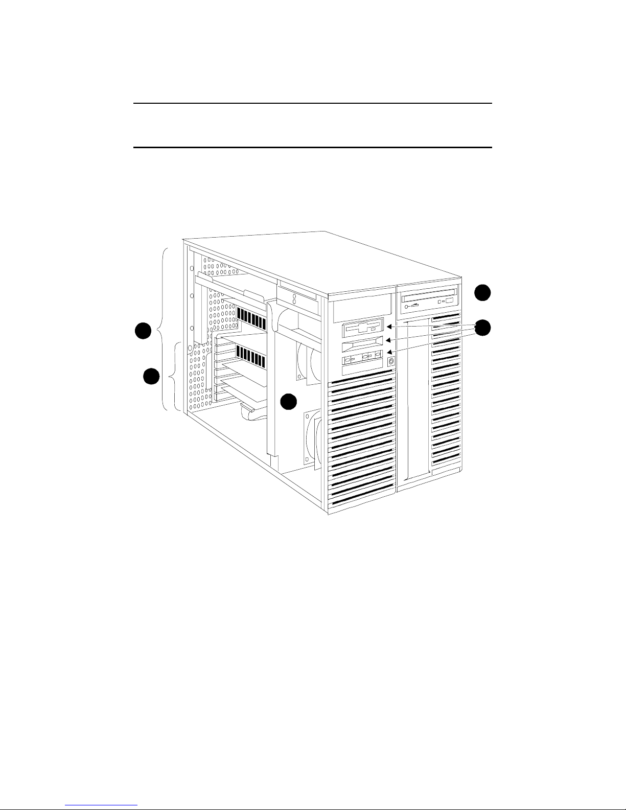
Figure 1-1 1200 System
4
1
1-2
3
2
5
PKW -0500- 97
The numbered callouts in Figure 1-1 refer to components of the system.
²
System card cage, which holds the system motherboard and the CPU, and
memory, and system I/O.
³
PCI/EISA section of the system card cage.
´
Server Control panel assembly, whic h i ncl ude s the c ont rol pa ne l, t he LCD
display, and the floppy dri ve.
µ
CD-ROM drive.
Cooling section containing two fans.
Cover Interlocks
The system has a single cover interlock switch on the top cover.
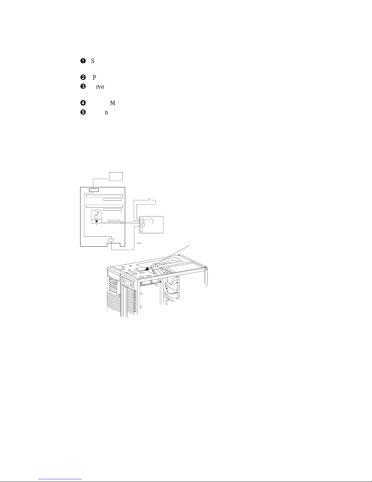
Figure 1-2 Cover Interlock Circuit
PowerSupply
J30
Switch
pack
Motherboard
J2
J7
Cover
Interlock
Push button
ON/OFF
OCP
DC_ENABLE_L
Cover
Interlock
Switch
PKW0503-97
NOTE: The cover interlocks must be engaged to e nabl e powe r-up.
To override the cover interlock, find a suitable object to close the interlock circuit.
System Overview 1- 3
1.2 Control Panel and Drives
The control panel includes the On/Off, Halt, and Reset buttons and an LCD
display.
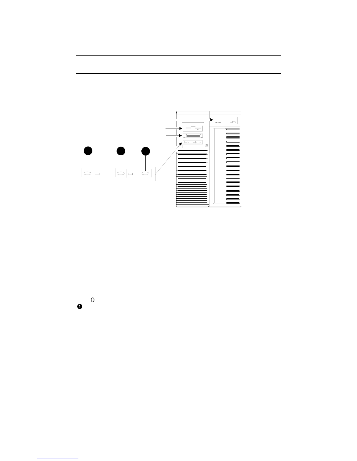
Figure 1-3 Control Panel Assembly
CD ROM
Floppy
OCP Display
1
OCP display. The OCP display is a 16-character LCD that indicates status
during power-up and self-test. While the operating system is running, the LCD
displays the system type. Its controller is on the XBUS.
CD-ROM drive. The CD-ROM drive is used to load software, firm ware , and
updates. Its controller is on PCI1 on the PCI backplane on the system
motherboard.
Floppy disk drive. The floppy drive is used to l oa d software a nd fi rmware
updates. The floppy controller is on the XBUS on the PCI backplane on the
system motherboard.
On/Off button. Powers the system on or off. When the LED to the right of the
²
button is lit, the power is on. The On/Off button is connected to the power
supplies through the system interlock and the RCM logic.
2
3
PKW-0501-97
1-4

³
Halt button. When the halt button is pressed, different results are manifest
depending upon the state of the machine. These states/results follow:
Machine State Result of pressing the Halt button
OpenVMS running/hung Simple halt. The SRM console
runs.
DIGITAL Unix running/hung Simple halt. The SRM console runs.
Windows NT running/hung Ignored.
AlphaBIOS running/hung Ignored.
SRM Console running Sets halt assertion flag; the SRM console
continues to run.
SROM (1
st
2 secs. of pwr-up) Not see n by the SROM firmware.
XSROM power up Sets halt assertion flag; auto boot ignored
SRM console power-up Sets halt assertion flag; auto boot ignored
A simple halt causes suspension of a system that is hung or running UNIX or
OpenVMS and drops back to t he SRM c onsol e .
The halt assertion flag is a set in the TOY NVRAM; it is read
and cleared by the console only during powered up or reset.
When the SRM console finds the halt assertion flag set, the
conditions of the environment variables auto_action =
boot/restart and os_type = NT are ignored; the SRM console
runs and prints the following message:
Halt assertion detected
NVRAM power-up script not executed
AUTO_ACTION=BOO T/RESTAR T and O S_TYPE =NT ignored, if applicable.
P000>>>
Some reasons for using the halt button:
1. The SRM console can be password protected. If the password is forgotten,
the Halt button can be used to regain control of the console. A new
password can then be set. See the A lphaSe rve r 1200 User’s Guide.
2. If the NVRAM power-up script becomes corrupt or is inadvert e ntl y
modified incorrectly, it can be bypassed and then edited by using the halt
button. See the AlphaServer 1200 User’s Guide.
Halt func t i o ns di f fer when oper a ting the system r emotely; se e Appendix A
and C.
1
´
Reset button. Initializes the system.
1
Halt button pressed after the console checks whether to run NVRAM script but before it
checks auto_action results in the NVRAM script running but no operating system is booted.
System Overview 1- 5
1.3 System Consoles
6
There are two console programs: the SRM console and the AlphaBIOS console.
SRM Console Prompt
On systems running the DIGITAL UNIX or OpenVMS operating system, the
following console prompt is displayed after system startup messages are displayed,
or whenever the SRM console is invoked:
P00>>>
NOTE: The console prompt displays only after the entire power-up sequence is
complete. This can take up to several minutes if the memory is very large.
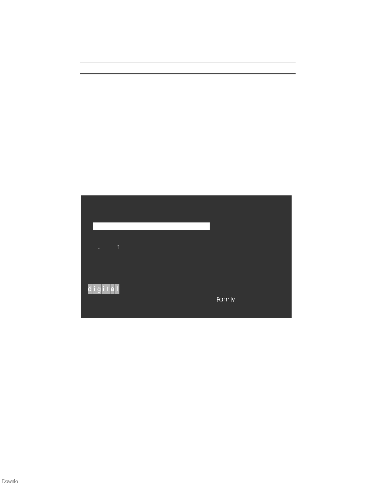
AlphaBIOS Boot Menu
On systems running the Windows NT operating system, the Boot menu is displayed
when the AlphaBIOS console is invoked:
AlphaBIOS 5.32
Please select the operating system to start:
Windows NT Server 4.0
Use and to move the highlight to your choice.
Press Enter to choose.
$OSKD6 HUYHU
1-6
)DPLO\
Press <F2> to enter SETUP
PK-0728C-9

SRM Console
The SRM console is a command-line interface that is used to boot the DIGITAL
UNIX and Open VMS o perating systems. It also provides support for examining and
modifying the system state and configuring and testing the system. The SRM
console can be run from a serial terminal or a graphics monitor.
AlphaBIOS Consol e
The AlphaBIOS console is a menu-based interface that supports the Microsoft
Windows NT operating system. AlphaBIOS is used to set up operating system
selections, boot Windows NT, and display information about the system
configuration. The EISA Configuration Utility and the RAID Standalone
Configuration Utility are run from the AlphaBIOS console. AlphaBIOS runs on
either a serial or graphics terminal. Windows NT requires a graphics monitor.
Environme nt Variabl es
Environment variables are software parameters that define, among other things, the
system configuration. They are used to pass information to different pieces of
software running in the system at various times. The os_type environment variable,
which can be set to VMS, UNIX, or NT , determines which of the two consoles is
used. The SRM console is always brought into memory, but AlphaBIOS is loaded if
os_type is set to NT and the Halt LED is not lit.
Refer to Appendix B of this guide for a l i st of the e nvironm e nt va ri abl e s used to
configure a1200 system.
Refer to the AlphaServe r 1200 Owner’s Manual for information on setting
environment variables.
Most environment variables are stored in the NVRAM that is placed in a socket on
the system motherboard. Even though the NVRAM can be removed and replaced on
a new system motherboard, it is recommended that you keep a record of the
environment variables for each system that you service. Some environment variable
settings are lost when a module is swapped and must be restored after the new
module is installed. Refer to Appendix B for a convenient worksheet for recording
environment variable settings.
System Overview 1- 7
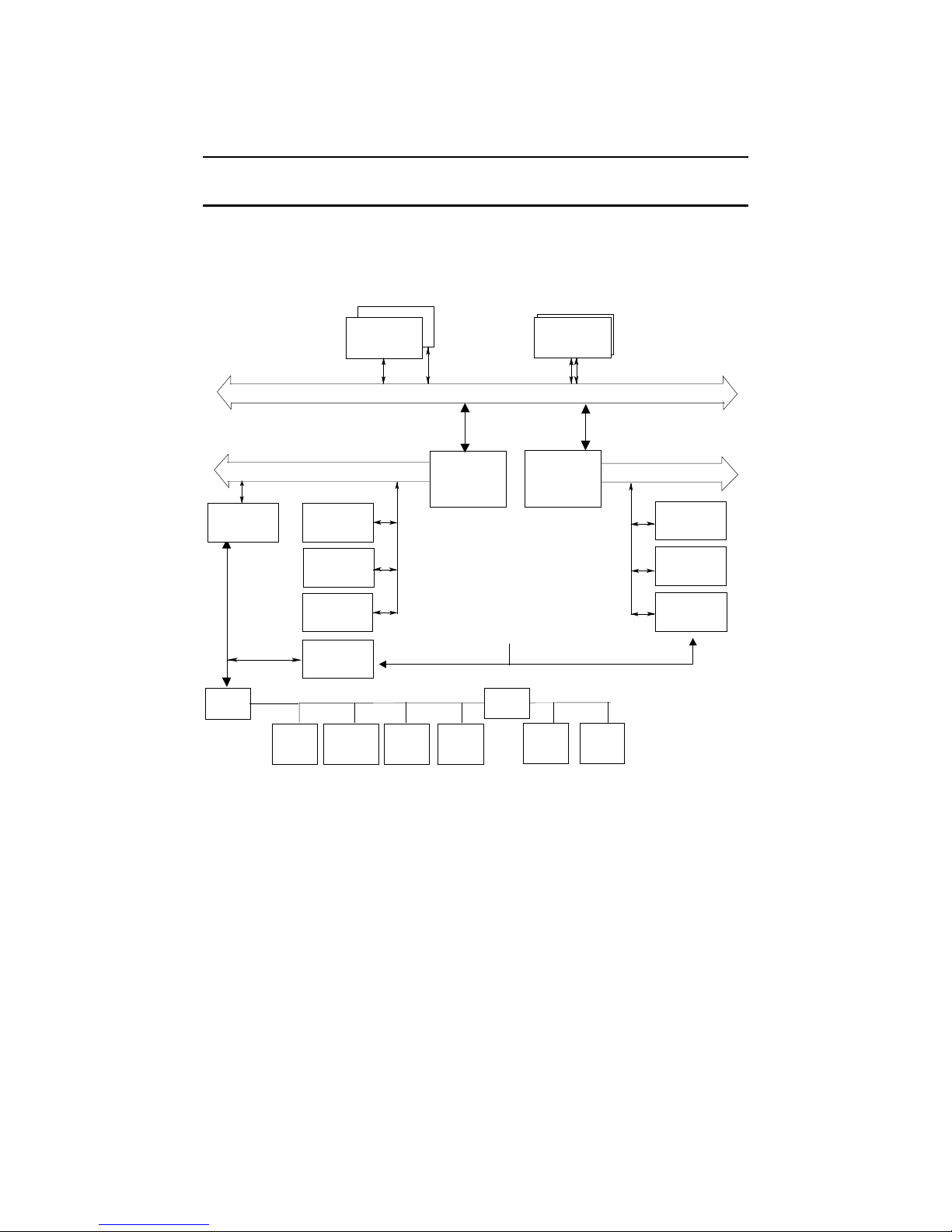
1.4 System Architecture
Alpha microprocessor chips are used in these systems. The CPU, memory, and
the I/O module(s) are connected to the system motherboard.
Figure 1 -4 Archit ecture Diagr am
EISA
Bridge
EISA
Bus
XBUS
Xceivers
CPU
Memory
Pair
System Bus
128-Bit Data Bus + 16 ECC and 40-Bit Command/Address Bus
PCI Bus 0
64 Bits
PCI Slot
System to
PCI Bus
Bridge 0
IOD0
System
System to
PCI Bus
Bridge 1
IOD1
PCI Bus 1
Motherboard
PCI Slot
Note: When the ISA slot on
PCI Slot
PCI Bus 0 is used, the last
PCI slot on PCI Bus 1 is not
available.
EISA Slot
Real-Time
Clock
Combo I/O:
serialports
parallel port
floppy cntrl
XBUS
Mouse/
Keyboard
Interface
I2C Bu s
BDATA
Xceivers
NVRAM
8Kx8
Flash
ROM
2MB
64 Bits
PCI Slot
PCI Slot
PCI Slot
1-8
PKW0502-97

AlphaServer 1200 systems use the Alpha chip for the CPU. The CPU, memory, and
I/O devices connect to the system motherboard. On the system motherboard is:
• the system bus
• two system bus to PCI bus chip sets that bridge two PCI busses to the system bus
• two 64-bit PCI busses with three PCI options slots each
• one EISA/ISA bus bridged to one of the PCIs (If an EISA/ISA option is used,
one PCI slot cannot be used)
• one CD-ROM controller built-in to the other PCI
• one EISA/ISA to XBUS bridge to the built-in XBUS options
A fully configured 1200 system can have two CPUs, one memory pair, and a total of
six I/O options. The I/O options can be all PCI options or a combination of PCI
options and a single EISA/ISA option.
The system bus has a 144-bit data bus, protected by 16 bits of ECC, and a 40-bit
command/address bus, protected by parity. The bus speed depends on the speed of
the CPU in slot 0 that provides the c l ock for t he buses. T he 40-bi t addre ss bus can
create one terabyte of addresses (that’s a million billion). The bus connects CPUs,
memory, and the system bus to PCI bus bridge(s).
The CPU modules have an external cache. The Alpha chip has an 8-Kbyte
instruction cache (I-cache), an 8-Kbyte write-through data cache (D-cache), and a
96-Kbyte, write-back secondary data cache (S-cache). The cache system is writeback. The system supports up to two CPUs.
Memory on 1200 systems is constructed of DIMM memory pairs place onto two
memory modules called riser cards. The riser cards are placed into the two memory
slots on the system motherboard. One member of a DIMM pair is placed onto one
riser card, and the other member is placed onto another riser card. Each riser card
drives half of the system bus, along with the associated ECC bits. Memory pairs
consist of two synchronous DIMMs of the same size and are placed into the same
slot on each riser card.
The system bus to PCI bus bridge chip set translates system bus commands and data
addressed to I/O space to PCI commands and data. It also translates PCI bus
commands and data addressed to system memory or CPUs to system bus commands
and data. The PCI bus is a 64-bit wide bus used for I/O.
Logic and sensors on the system motherboard monitor power status and the system
environment (temperature and fan speeds).
System Overview 1- 9

1.5 CPU Types
There are several CPU variants differentiated by CPU speeds.
Figure 1 -5 CPU Module Placement
PCI 0 Slot 2
PCI 0 Slot 3
PCI 0 Slot 4
PCI 1 Slot 2
PCI 1 Slot 3
PCI 1 Slot 4
ISA Slot
RCM
Switchpack
Powerconnectors
Floppy
connector
OCP
connector
Fan
connectors
CPU 0
MEM L
CPU 1
MEM H
LEDs
Internal SCSI
connector
Speaker
connector
PKW0504A-97
PCI Bridges
1-10

Alpha Chip Composition
The Alpha chip is made using state-of-the-art chip technology, has a transistor count
of 9.3 million, consumes 50 watts of power, and is air cooled (a fan is on the chip).
The default cache system is write-back and when the module has an external cache,
it is write-back.
Chip Description
Unit Description
Instruction 8-byte cache, 4-way issue
Execution 4-way execution; 2 inte ge r unit s, 1 fl oa ti ng-poi nt a dde r,
1 floating-point multiplier
Memory Merge logic, 8-Kbyte write-through first-level data cache,
96-Kbyte write-back second-level data cache, bus
interface unit
CPU Variants
Module Variant Clock Frequency Onboard Cache Color
B3007-AA 400 MHz 4 Mbytes Orange
B3007-CA 533 MHz 4 Mbyte s Violet
CPU Config uration Rules
• The first CPU must be in CPU slot 0 to provide the system clock.
• The second CPU should be installed in CPU slot 1.
• Both CPUs mu st h a v e the same Alpha chip clock speed. The system bus will
hang without an error message if the oscillators clocking the CPUs are differe n t .
System Overview 1- 11

1.6 Memory
Memory consists of two riser cards and up to eight pairs of DIMMs. Each riser
card receives one of the two DIMMs in the DIMM pair. There are two DIMM
variants: a 32MB version and a 128MB version.
Figure 1-6 Memory Placement
PCI 0 Slot 2
PCI 0 Slot 3
PCI 0 Slot 4
PCI 1 Slot 2
PCI 1 Slot 3
PCI 1 Slot 4
ISA Slot
RCM
Switchpack
Powerconnectors
Floppy
connector
OCP
connector
Fan
connectors
CPU 0
MEM L
CPU 1
MEM H
LEDs
Internal SCSI
connector
Speaker
connector
PKW0504B-97
PCI Bridges
1-12

Memory Variants
Memory consists of two riser cards supporting 8 DIMM pairs. There are two DIMM
variants: a 32MB version and a 128MB version. Maximum memory using 32MB
DIMMs is 512MB and the max im u m me m ory usi ng 128MB DIMMs i s 2GB. Al l
memory is synchronous
DRAM
Option Size Module Type Number Size
MS300-BA 64 MB 54-25084-DA
20-47405-D3
MS300-DA 256 MB 54-25092-DA
20-45619-D3
Synch. 9 4M x 72 =
32MB
Synch. 9 16M x 72 =
128MB
Memory Operation
Each DIMM in the pair provides half the data, or 64 bits plus 8 ECC bits, of the
octaword (16 byte) transferred on the system bus. DIMMs are placed in slots on the
riser cards and the riser cards are placed in the slots designated MEM L and MEM H
on the system motherboard.
NOTE: Memory in slot MEM L does not drive the lower 8 bytes, and memory in slot
MEM H does not drive the higher 8 bytes of the 16 byte transfer. Some bits
originating from MEM L are high order bits and some bits originating from MEM H
are low order bits.
Memory drives the system bus in bursts. Upon each memory fetch, data is
transferred in 4 consecutive cycles transferring 64 bytes.
Memory Configuration Rules
In a system, memories of different sizes are permitted, but:
• DIMMs are in stalled and used in pairs. Both DIMMs in a memory pair must be
of the same size.
• Each riser card receives one of the two DIMMs in the DI MM pair.
• The largest memory pa i r must be i n riser c a rd slot 0.
• Other memory pairs must be the same size or smaller than the first memory pair.
• Memory pairs must be installed in consecutive slots.
• Memory configurations that have a 64 MB pair in riser cars slot 0 are limited to
4 DIMM pairs or 256 MB for the system.
System Overview 1- 13
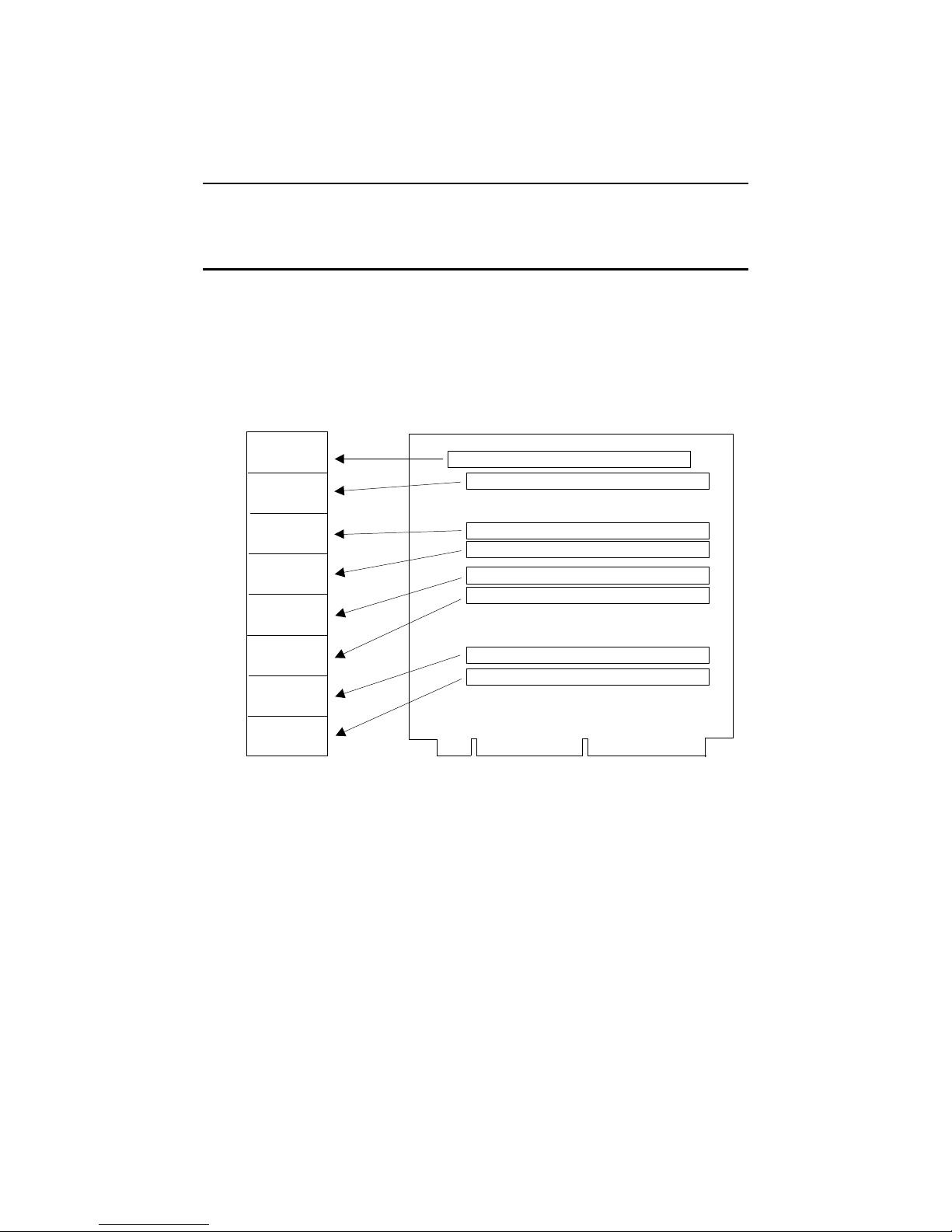
1.7 Memory Addressing
Memory addressing in these systems is fixed regardless of the size of the
DIMMs. The address of DIMM pair is fixed according to the slot in which the
pair is placed. The starting address of each pair in each slot on the riser card
starts on a 512 MB boundary.
Figure 1-7 How Memory Addressing Is Calculated
Address Space
GBytes
4.0
3.5
3.0
2.5
2.0
1.5
1.0
.5
0
e0000000
c0000000
a0000000
80000000
60000000
40000000
20000000
00000000
Riser Card
Slot
7
6
5
4
3
2
1
0
PKW0505-97
1-14

The rules for addr essing memory a re as follows:
1. A memory pair c onsi sts of 2 DIMMs of t he same size.
2. Memory pairs in riser cards may be of different sizes.
3. The memory pair in slot 0 must be the largest of all memory pairs. Other
memory pairs may be as la rge but none m ay be l arge r.
4. The physical starting address of each memory pair is N times 512MB (200
0000) where N is the slot number on the riser c a rd.
5. Memory addresses are contiguous within each module pair.
6. If memory pairs do not completely fill the 512MB space provided, memory
“holes” occur in the physical address space.
7. Software creates contiguous virtual memory even though physical memory may
not be contiguous.
System Overview 1- 15
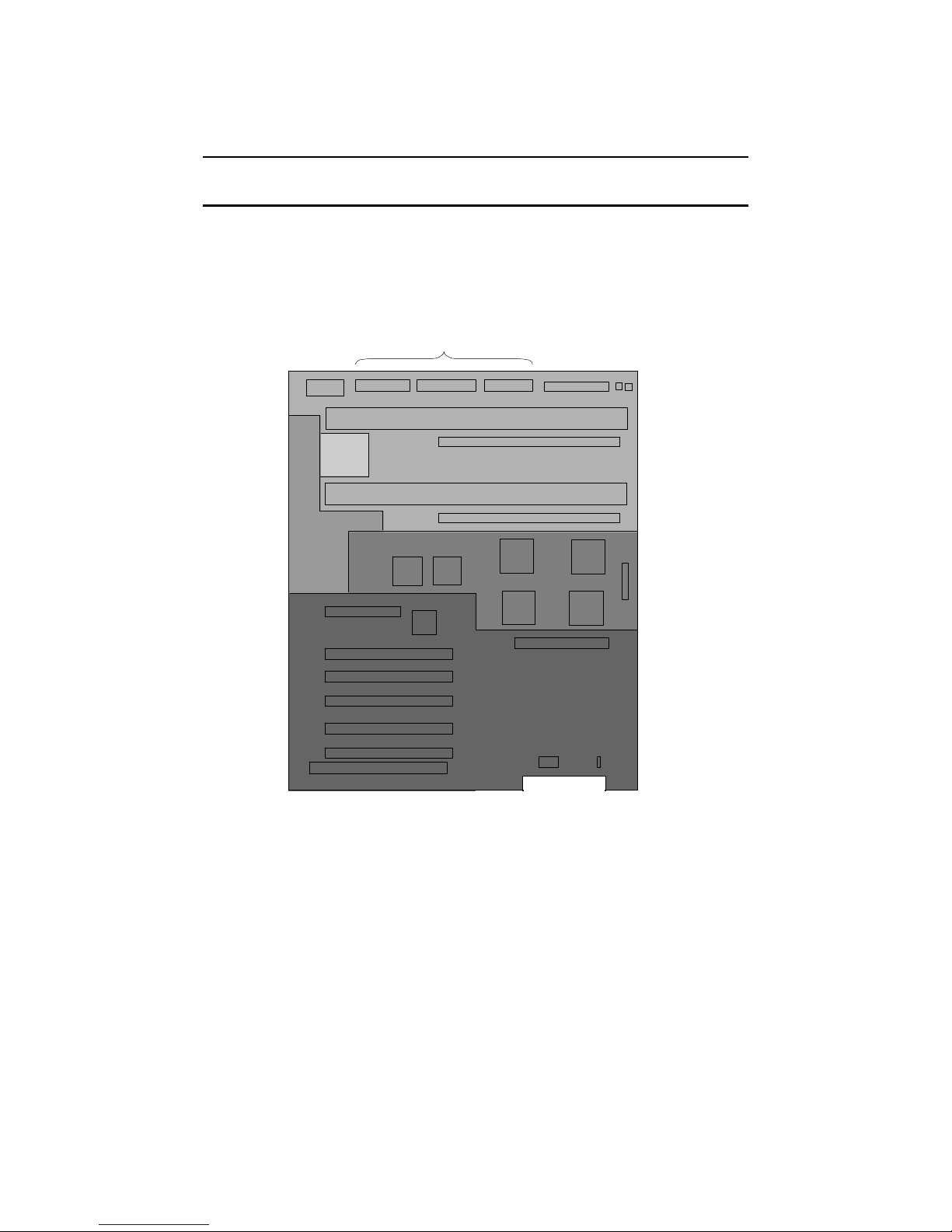
1.8 System Motherboard
The system motherboard contains five major logic sections performing five
major system functions.
Figure 1-8 System Moth erboard
PCI 0 Slot 2
PCI 0 Slot 3
PCI 0 Slot 4
PCI 1 Slot 2
PCI 1 Slot 3
PCI 1 Slot 4
ISASlot
Power
Control
Logic
Server
Control
Logic
Powerconnectors
CPU and Memory Backplane
System Bus
to
PCI Bus Bridges
PCI Backplane
and Legacy I/O
Devices
OCP
connector
Floppy
connector
Fan
connectors
CPU 0
MEM L
CPU 1
MEM H
Internal SCSI
connector
Speaker
connector
PKW0504F-97
1-16

The five sections on the system motherboard are:
• The system bus or the CPU and Memory backplane.
• The power control logic.
• The server control logic .
• The system bus to PCI bus bridges.
• The PCI backplane containing two PCI busses, an EISA/ISA bus, a built-in CD-
ROM controller, and an XBUS with several devices integral to the system on it.
System Overview 1- 17
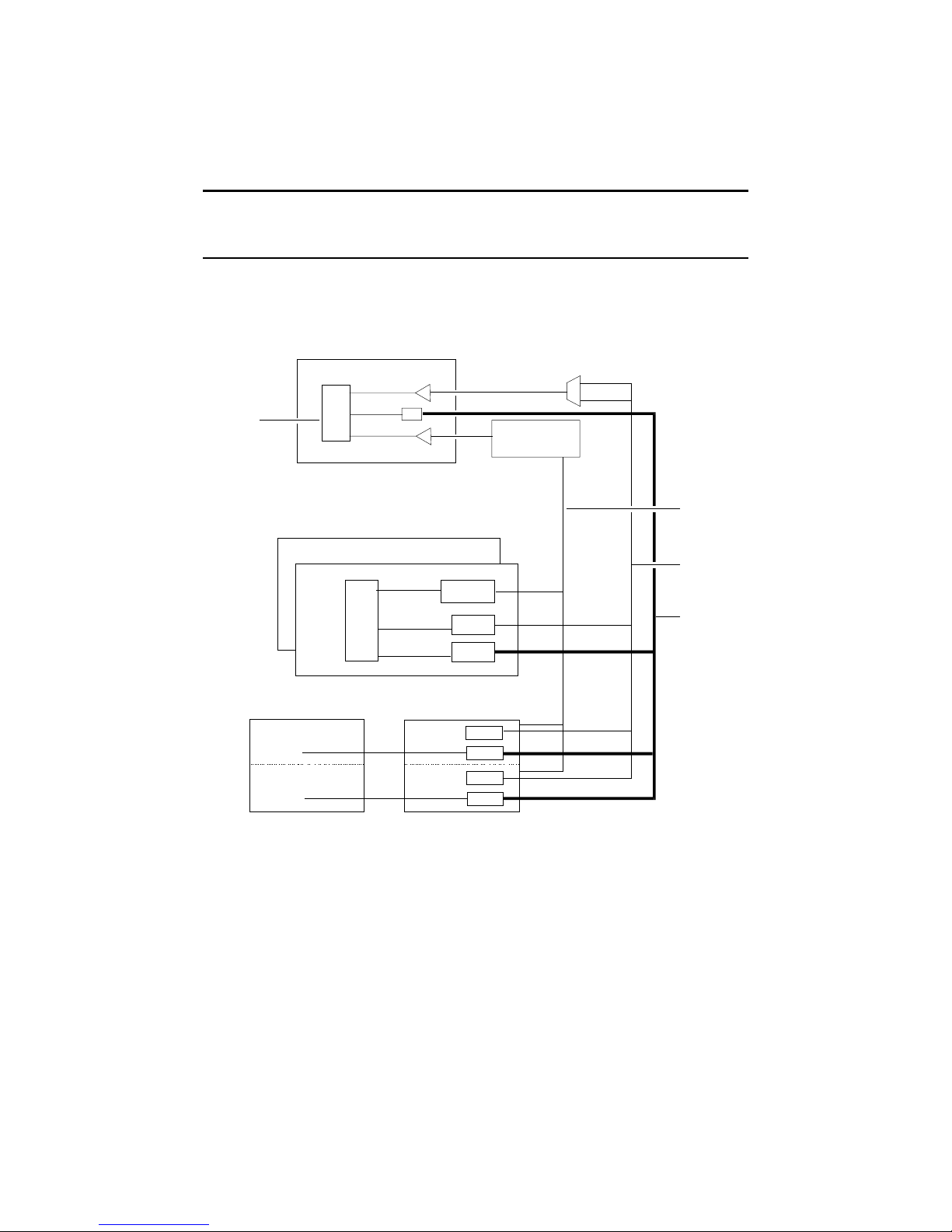
1.8.1 System Bus (Backplane)
The system bus consists of a 40-bit c ommand/address bus, a 128-bit plus ECC
data bus, and several control signals and clocks. The syste m bus is part of the
system motherboard.
Figure 1-9 System Bus B lock Diagram
SYNC
DRAMS
CPU1
CPU0
PCI/ISA
PCI/ISA0
PCI1
MEM0
ADR
DA T A
CTRL
A
L
P
H
A
CTRL
EV_ADR
EV_DATA
MC to PCI Bridge
IOD0
IOD1
SIM_ADR
MEM CTRL&
CNTRL ARB
ROW
COL
ADR
MC Bus
Control
MC ADR
<39:4>
MC DATA
<127:0>
1-18
PKW0506-97
 Loading...