

Digital Equipment Digital Server 3220 Series, Digital Server 3220R Series System Reference Manual

DIGITAL Server 3220/3220R Series
System Reference
Part Nu mb e r: E R-B4BWW -U A. A01
Digital Equipment Corporation

June 1998
The information in this document is subject to change without notice and should not
be construed as a commitment by Digital Equipment Corporation.
Digital Equipment Corporation assumes no responsibility for any errors that might
appear in this document.
The software, if any, described in this document is furnished under a license and may
be used or copied only in accordance with the terms of such license. No responsibility
is assumed for the use or reliability of software or equipment that is not supplied by
Digital Equipment Corporation or its affiliated companies.
Restricted Rights: Use, duplication, or disclosure by the U.S. Government is subject
to restrictions as set forth in subparagraph (c) (1) (ii) of the Rights in Technical Data
and Computer Software clause at DFARS 252.227-7013.
DIGITAL Se r ve r 3220/3220R Series System Reference
© 1998 Digital Equipment Corporation.
All Rights Reserved.
AMI is a registered trademark of American Megatrends, Inc.
DEC, DIGITAL, ServerWORKS , and the DIGITAL logo are trademarks of Digital
Equipment Corporation.
Intel, MMX and Pentium II are registered trademarks of Intel Corporation.
Microsoft, Windows NT, and Windows 95 are registered trademarks of Microsoft
Corporation.
Novell and NetWare are U.S. registered trademarks of Novell Inc.
OS/2 and PS/2 are registered trademarks of International Business Machines
Corporation.
PhoenixBIOS is a trademark of Phoenix Technologies Ltd.
SCO UNIX is a trademark of The Santa Cruz Operation, Inc.
Symbios is a trademark of Symbios, Inc.
UNIX is a registered trademark of The Open Group.
All other trademarks and registered trademarks are the property of their respective
holders.

Regulatory Compliance Statements
The following statements of compliance are required by the respective governmental
regulatory agencies.
DIGITAL Server 3220R (Rackmount Model)
FCC Notice — U.S.A.
This equipment has been tested and found to comply with the limits for a Class A
digital device, pursuant to Part 15 of the FCC rules. These limits are designed to
provide reasonable protection against harmful interference when the equipment is
operated in a commercial environment. This equipment generates, uses, and can
radiate radio frequency energy and, if not installed and used in accordance with the
instruction manual, may cause harmful interference to radio communications.
Operation of this equipment in a residential area is likely to cause harmful
interference, in which case, the user will be required to correct the interference at his
own expense.
CAUTION:
Any changes or modifications t o this device, whic h
are not identif ied in this manual, could c aus e har m ful
interferenc e and v oid the user’s author ity to operat e this device.
CSA — Canada
This digital apparatus does not exceed the Class A limits for radio noise emissions
established in the radio interference regulations of the Canadian Department of
Communications.
VCCI — Japan
This equipment is in the Class I category (information equipment to be used in
commercial and/or industrial areas) and conforms to the standards set by the
Voluntary Control Council for Interference (VCCI) by Data Processing Equipment and
Electronic Office Machines aimed at preventing radio interference in commercial
and/or industrial areas.
Consequently, when used in a residential area or in an adjacent area thereto, radio
interference may be caused to radio and TV receivers, etc.
Read the instructions for correct handling.

DIGITAL Server 3220 (Pedestal Model)
FCC Notice — U.S.A.
This equipment has been tested and found to comply with the limits for a Class B
digital device, pursuant to Part 15 of the FCC rules. These limits are designed to
provide reasonable protection against harmful interference in a residential installation.
This equipment generates, uses, and can radiate radio frequency energy and, if not
installed and used in accordance with the instructions, may cause harmful
interference to radio communications. However, there is no guarantee that
interference will not occur in a particular installation. If this equipment does cause
harmful interference to radio or television reception, which can be determined by
turning the equipment off and on, the user is encouraged to try to correct the
interference by one or more of the following measures:
• Reorient or relocate the receiving antenna
• Increase the separation between the equipment and receiver.
• Connect the equipment into an outlet on a circuit different from that to which
the receiver is connected.
• Consult the dealer or an experienced radio/TV technician for help.
All external cables connecting to this basic unit need to be shielded. For cables
connecting to option boards, see the option manual or installation instructions.
CSA — Canada
This digital apparatus does not exceed the Class B limits for radio noise emissions
established in the radio interference regulations of the Canadian Department of
Communications.
VCCI — Japan
This equipment is a Class II product based on the standard of the Voluntary Control
Council for Interference Technology Equipment (VCCI). If it is used near a radio or
television receiver in a domestic environment, it may cause radio interference. Install
and use the equipment according to the instruction manual.

DIGITAL Server 3220/3220R
Ergonom ics — Germany
This equipment meets or exceeds the ergonomic requirements of ZH1/618, TÜV,
Rheinland, Germany.
Safety Requir ements
This equipment meets or exceeds safety requirements in the U.S. (UL 1950),
Canada (CSA C22.2 No. 950), and Europe (IEC 950 and TÜV EN60950/A3: 1995).
The product is certified to bear the GS-Mark (Geprüfte Sicherheit) and CB
certification.
Laser Safety Notice
All CD-ROM drives included in DIGITAL compu te r s a r e cl a s si fied as Class 1 laser
products and comply with safety standards as set by U.S. government and applicable
European agencies.
No hazardous radiation is emitted from this CD-ROM drive; the laser beam is
completely enclosed in the CD-ROM subassembly during all customer operation and
maintenance. In the event that repair or service of the CD-ROM subassembly is
required, only authorized DIGITAL servi ce p e r sonnel should perform such repairs.

i
Contents
Preface
Introduction..................................................................................................... ix
Audience......................................................................................................... ix
Support Information......................................................................................... x
Organization.................................................................................................... xi
Conventions.................................................................................................... xiii
Abbreviations .................................................................................................. xiv
Special Notices................................................................................................ xvii
1
Introduction
Reliability/Availability........................................................................................ 1-1
Server Expansion............................................................................................ 1-2
Server Management and Security.................................................................... 1-3
Server Software and Documentation ............................................................... 1-4
Diagnostic Software......................................................................................... 1-5
Server Utilities and Technical Support.............................................................. 1-6
2
Server Software and Utilities
Introduction..................................................................................................... 2-1
ServerWORKS Quick Launch.......................................................................... 2-2
BIOS Setup Utility............................................................................................ 2-2
Accessing the BIOS Setup Utility.............................................................. 2-4
Helpful Hints............................................................................................. 2-5
Changing Your Server’s Configuration............................................................. 2-6
Changing Time and Date.......................................................................... 2-6
Changing I/O Port Settings....................................................................... 2-7

Contents
ii
Assigning IRQs ............................................................................................... 2-8
Advanced................................................................................................. 2-8
Setting Up Security................................................................................... 2-9
Changing the Boot Sequence ................................................................... 2-13
Speeding up the Boot Process.................................................................. 2-13
Checking System Management Parameters ............................................. 2-15
BIOS Upgrade Utility ....................................................................................... 2-15
SCSI Configuration Utility ................................................................................ 2-17
Determining Devices Attached to Each SCSI Channel............................... 2-18
RAID Configuration Utility................................................................................ 2-19
Diagnostics ..................................................................................................... 2-19
3
Server Components
Introduction..................................................................................................... 3-1
Disconnecting External Devices and Power ..................................................... 3-1
Unlocking the Server (Model 3220).................................................................. 3-2
Keylock Function...................................................................................... 3-2
Removing the Front Bezel............................................................................... 3-2
Removing and Installing the Side Panel (Model 3220)...................................... 3-4
Removing the Server from the Rack (Model 3220R)........................................ 3-6
Removing and Installing the Top Cover (Model 3220R).................................... 3-8
Front View....................................................................................................... 3-12
Internal View................................................................................................... 3-14
Rear View ....................................................................................................... 3-16
Main Logic Board Connectors.......................................................................... 3-18
Main Logic Board Components........................................................................ 3-20
Processor Module Components....................................................................... 3-22
Video/Ethernet Daughter Card Connectors and Indicators ............................... 3-24
Tools Needed.................................................................................................. 3-25
Static Electricity............................................................................................... 3-25
Replacing the Real Time Clock (RTC) Battery.................................................. 3-26

Contents
iii
4
Server Management
Introduction..................................................................................................... 4-1
Managing Your Server..................................................................................... 4-1
Obtaining Information about Your Server......................................................... 4-2
Obtaining Information Using the BIOS Setup Utility................................... 4-4
Obtaining Information Using Server Management Software....................... 4-4
Displaying Server Status Using the Hardware.................................................. 4-6
5
Processor Upgrades
Introduction..................................................................................................... 5-1
Processor Configuration Guidelines................................................................. 5-1
Removing the Processor Module..................................................................... 5-2
Removing the Terminator Card........................................................................ 5-4
Installing a Second Processor.......................................................................... 5-5
Installing the Processor Module....................................................................... 5-6
Run the System ID Configuration Utility ........................................................... 5-8
6
Installing Additional Memory
Introduction..................................................................................................... 6-1
Server DIMM Requirements............................................................................ 6-2
Memory Configuration Guidelines.................................................................... 6-2
Memory Configurations............................................................................. 6-4
Installing DIMMs on the Processor Module...................................................... 6-5
Memory Troubleshooting................................................................................. 6-8

Contents
iv
7
SCSI Device Configurations
Introduction..................................................................................................... 7-1
Storage Configuration Guidelines .................................................................... 7-1
SCSI Configuration Guidelines......................................................................... 7-2
Tape Drive Configuration Guidelines................................................................ 7-3
Hot Swap Drive Configuration Guidelines......................................................... 7-4
SCSI IDs (Model 3220R) .......................................................................... 7-6
RAID Configuration Guidelines ........................................................................ 7-7
Cables...................................................................................................... 7-8
8
Installing Storage Devices (DIGITAL Server 3220)
Introduction..................................................................................................... 8-1
Installing a Half-Height 5¼-Inch Device into the Top Drive Bay.................. 8-1
Installing a Full-Height 5¼-Inch Device into the Top Drive Bay.................. 8-4
Hot-Swap Drive Bay ................................................................................. 8-7
Installing the External Wide SCSI Cable Assembly........................................... 8-10
Connecting an External SCSI Storage Box ...................................................... 8-12
9
Installing Storage Devices (DIGITAL Server 3220R)
Introduction..................................................................................................... 9-1
Installing a Half-Height 5¼-Inch Device
into the Front Access Drive Bay........................................................... 9-2
Installing a Full-Height 5¼-Inch Device
into the Front Access Drive Bay........................................................... 9-6
Hot-Swap Drive Bay ................................................................................. 9-8
Connecting the External Wide SCSI Cable Assembly....................................... 9-14

Contents
v
10
Installing Expansion Boards
Introduction..................................................................................................... 10-1
ISA Expansion Board Configuration Guidelines................................................ 10-1
PCI Expansion Board Configuration Guidelines................................................ 10-3
Configuring PCI Expansion Boards Using the BIOS Setup Utility...................... 10-4
Boot Devices............................................................................................ 10-4
Server Boot Sequence.............................................................................. 10-5
Server Scan Sequence............................................................................. 10-6
PCI Scan Sequence ................................................................................. 10-7
Installing Expansion Boards............................................................................. 10-9
11
Connecting SCSI and RAID Devices
Introduction..................................................................................................... 11-1
SCSI Cable Configurations.............................................................................. 11-1
Wide Ultra SCSI Cable Configuration........................................................ 11-1
RAID Cable Configuration................................................................................ 11-4
12
Server Security Features
Introduction..................................................................................................... 12-1
Hold-Down Bar (Model 3220)........................................................................... 12-2
Front-Access Security Door and Front Bezel Lock (Model 3220)...................... 12-3
Supervisor Password....................................................................................... 12-4
If You Forget Your Password........................................................................... 12-4
Additional Security Features............................................................................ 12-5

Contents
vi
13
Troubleshooting
Introduction..................................................................................................... 13-1
Initial Troubleshooting...................................................................................... 13-2
When to Use the Diagnostics........................................................................... 13-3
Running the Diagnostics........................................................................... 13-4
Running Quick Tests or Groups of Tests................................................... 13-4
Running DIGITAL Vendor Extended Tests................................................ 13-5
Running the Diagnostics Tests from the Server’s Hard Disk Drive............. 13-5
Server Troubleshooting ................................................................................... 13-6
Disk Drive Troubleshooting.............................................................................. 13-10
Hot Swap Drive Troubleshooting (Model 3220) ................................................ 13-13
Hot Swap Drive Troubleshooting (Model 3220R).............................................. 13-13
Tape Drive Troubleshooting............................................................................. 13-14
Monitor Troubleshooting.................................................................................. 13-15
CD-ROM Troubleshooting ............................................................................... 13-16
Diskette Drive Troubleshooting........................................................................ 13-17
RAID Troubleshooting Hot Swap Drives........................................................... 13-18
Flash BIOS Troubleshooting............................................................................ 13-19
A
Technical Specifications
Introduction..................................................................................................... A-1
Server Specifications....................................................................................... A-2
DIGITAL Server 3220/3220R Performance Specifications......................... A-2
DIGITAL Server 3220 Dimensions............................................................ A-3
DIGITAL Server 3220R Dimensions.......................................................... A-3
Environmental Specifications.................................................................... A-4
ISA Expansion Slots........................................................................................ A-4
PCI Expansion Slots........................................................................................ A-4
Power Supply Input Power Requirements........................................................ A-5
Power Supply Output Specifications ................................................................ A-5
Power Cord Requirements............................................................................... A-5
Environmental Features................................................................................... A-6
Acoustic Levels ............................................................................................... A-7

Contents
vii
Main Logic Board Switch Settings.................................................................... A-8
Processor Module Switch Settings................................................................... A-10
Server Fault Status................................................................................... A-12
POST Messages............................................................................................. A-13
POST/Boot Codes.................................................................................... A-13
Processor Module Voltage and Temperature Ranges ...................................... A-14
Processor Voltage Range......................................................................... A-14
Processor Voltage Range (V
ccp
).............................................................. A-15
Processor Temperature Sensing............................................................... A-16
B
Device Mapping
Introduction..................................................................................................... B-1
Processor Memory Address Map.............................................................. B-2
I/O Address Map...................................................................................... B-3
Server Interrupt Levels............................................................................. B-4
PCI Configuration Space Address Map..................................................... B-4
C
BIOS Setup Utility Features
Introduction..................................................................................................... C-1
BIOS Setup (F2).............................................................................................. C-2
Main......................................................................................................... C-2
Advanced................................................................................................. C-7
Security Options....................................................................................... C-13
Boot......................................................................................................... C-15
System Management (F3)............................................................................... C-16

Contents
viii
D
Caring For Your Server
Introduction..................................................................................................... D-1
Cleaning the Server......................................................................................... D-2
Cleaning the Screen........................................................................................ D-2
Cleaning the Mouse......................................................................................... D-2
Moving the Server........................................................................................... D-3
Packing the Server................................................................................... D-3
Installing the Server at a New Location..................................................... D-3
Index.................................................................................................................. IN-1

Contents
ix
Figures
Typi ca l DIGITAL S e rv e r 3220 (Top) and 3220R (Bottom) ................................................. xviii
2-1. Typical BIOS Setup Utility Screen.............................................................................. 2-3
3-1. Front-Access Security Door and Front Bezel Lock .................................................... 3-3
3-2. Re mo ving the DIGITAL S e rv e r 3220 Side Panel....................................................... 3-4
3-3. Insta llin g th e D IGIT AL Serve r 3220 Side Panel......................................................... 3-5
3-4. Re mo v i n g th e Server from th e Rack.......................................................................... 3-6
3-5. Disconnecting the Cable Management Arm .............................................................. 3-7
3-6. Re mo ving the DIGITAL S e rv e r 3220R Top Cover..................................................... 3-9
3-7. Insta llin g th e D IGIT AL Serve r 3220R Top Cover....................................................... 3-11
3-8. DIGIT AL Serve r 3220/3220R Front View................................................................... 3-13
3-9. DIGIT AL Serve r 3220/3220R Internal View............................................................... 3-15
3-10. D IGIT AL Serve r 3220/3220R Rear View................................................................. 3-17
3-11. Main Logic Board Connectors.................................................................................. 3-19
3-12. Main Logic Board Components................................................................................ 3-21
3-13. Processor Module Components............................................................................... 3-23
3-14. Video/Ethernet Daughter Card Connectors ............................................................. 3-24
3-15. R e p lacin g th e S e rv e r B a tte ry /R TC........................................................................... 3-27
4-1. DIGIT A L S e rv e r C o mponent Information................................................................... 4-3
5-1. Removing the Processor Module............................................................................... 5-3
5-2. Removing the Terminator Module.............................................................................. 5-4
5-3. Installing the Second Processor................................................................................. 5-5
5-4. Installing the Processor Module................................................................................. 5-7
6-1. DIMM B a n k L o c a ti o n s................................................................................................ 6-3
7-1. Model 3220 Storage Backplane Switch Location....................................................... 7-5
7-2. Model 3220R Storage Backplane SCSI Drive IDs ..................................................... 7-6
8-1. Insta llin g a H a lf-Hei g h t 5 ¼-In ch Devic e In to th e T o p D r i v e B a y................................. 8-3
8-2. Insta llin g a F u l l-Hei g h t 5 ¼-In c h D e v ice Into th e T o p Drive B a y................................. 8-5
8-3. Installing 3½-Inch Expansion Brackets ...................................................................... 8-6
8-4. Re mo v i n g a Devic e fro m th e H o t-Swap D r i v e B a y.................................................... 8-8
8-5. Insta llin g th e E x te rn a l W i d e SCSI C a b l e Assembl y .................................................... 8 - 1 1
8-6. Connecting an External SCSI Storage Box................................................................ 8-13

Contents
x
9-1. Re mo v i n g th e Diske tte D rive...................................................................................... 9-3
9-2. Insta llin g a H a lf-Hei g h t 5 ¼-In ch Devic e In to th e F ro n t A c c e s s Drive B a y.................. 9-5
9-3. Insta llin g a F u l l-Hei g h t 5 ¼-In c h D e v ice Into th e F ro n t Access Drive B a y ................... 9-7
9-4. Removing the Hot Swap Drive Bay Cage Cover........................................................ 9-9
9-5. Removing the Hot Swap Drive and Drive Tray .......................................................... 9-10
9-6. Insta llin g a H o t Swap D rive Into th e Hot Sw a p D rive Ba y.......................................... 9-11
9-7. SC SI Knoc ko u t L o c a tions.......................................................................................... 9-15
9-8. Cable Connections..................................................................................................... 9-16
9-9. Connecting an External SCSI Device......................................................................... 9-17
10-1. Expansion Board Slot Locations .............................................................................. 10-2
10-2. Removing a Metal Filler Plate .................................................................................. 10-9
10-3. Installing an Expansion Board.................................................................................. 10-10
11-1. Wide Ul tra SCSI C a b l e Config u ra tion...................................................................... 11-3
11-2. R A ID Cable Con figurati o n........................................................................................ 11-6
12-1. H o ld-Dow n Bar......................................................................................................... 12-2
12-2. Front-Access Security Door and Front Bezel Lock .................................................. 12-3
A-1. Main Logic Board Switch Locations........................................................................... A-9
A-2. Processor Module Switch Settings ............................................................................ A-11

xi
Preface
P
Introduction
This
System Reference
describes how to operate, upgrade, configure, and
troubleshoot your DIGITAL Serve r 3220/3220R. This
System Reference
will also
help to familiarize you with all aspects of the server and provide a reference tool for
questions you might have in the future.
If you are initially setting up your server, refer to the DIGITAL Serve r 3220/3220R
Series
Installation Guide
.
The
Installation Guide
identifies all the components that were shipped from the
factory as well as how to connect the mouse, keyboard, monitor, and ac power.
The
Installation Guide
shows how to turn your server on for the first time and access
the ServerWORKS Quick Launch program. You must run the ServerWORKS Quick
Launch program to initially configure your server, create utility and device driver
diskettes, and install an operating system.
Audience
This
System Reference
is written specifically for anyone responsible for operating,
configuring, and expanding the DIGITAL Serve r 3220/3220R.

Preface
xii
Support Information
A variety of support information is available to help you set up, configure, and operate
your D IGITA L Se rv e r. Th i s i n fo rm a tion comes in the form of README information,
on-line help, electronic books, or as printed material.
If you want to… Refer to th e …
Set up your server
Installation Guide
to unpack, install internal
components, connect external devices and power,
and access the ServerWORKS Quick Launch
program.
Load the supplied ServerWORKS Quick
Launch software
ServerWORKS Quick Launch Getting Started
guide.
README information contained on the
ServerWORKS Quick Launch CD-ROM discs.
Locate the major internal components of
your server
Quick Refere nce
label on the side panel of the
DIGITAL Server 3220 or the top cover of the DIGITAL
Server 3220R.
Check the fault status of the server Fault status LED codes label located on your server’s
front panel.
Upgrade and configure your server after
installing optional components (for
example, a processor module, memory,
mass storage devices, SCSI or RAID
adapters, etc.)
Information supplied in this
System Reference
.
Supplied SCSI, RAID, and other options
documentation. These are supplied as either printed
manuals or as electronic books on the Quick Launch
CD-ROM discs.
Run diagnostics
ServerWORKS Quick Launch Getting Started
guide
and the Quick Launch program on the supplied CDROM d iscs.
Supplied diagnostics documentation which is on the
Quick Launch CD-ROM discs.

Preface
xiii
Organization
This
System Reference
contains the following:
•
Chapter 1:
Introduction
— Provides information about your server, such as
features, server software and documentation, diagnostic software, server
utilities, and technical support.
•
Chapter 2:
Server Software and Utilities
— Describes the server software
and utilities that are supplied with your server.
•
Chapter 3:
Server Components
— Provides information about the server’s
components and associated procedures such as removing the top cover
(DIGITAL S e rve r 3220R only) and side panel (DIGITAL Se rv e r 3220 only).
•
Chapter 4:
Server Management
— Describes how to manage your server
using a network manager, specifically DIGITAL Serve r WOR KS Manager.
•
Chapter 5:
Processor Upgrades
— Describes how to upgrade your server
with higher-performance processor modules.
•
Chapter 6:
Installing Additional Memory
— Describes how to install
additional memory on a processor module.
•
Chapter 7:
SCSI Device Configuration
—Describes how to configure SCSI
devices for your server.
•
Chapter 8:
Installing Storage Devices (DIGITAL Server 3220)
— Describes
how to install optional hot swap drives, tape drives, and external SCSI or
RAID devices.
•
Chapter 9:
Installing Storage Devices (DIGITAL Server 3220R)
— Describes
how to install optional hot swap drives, tape drives, and external SCSI or
RAID devices.
•
Chapter 10:
Installing Expansion Boards
— Describes how to install ISA
and PCI expansion boards.

Preface
xiv
•
Chapter 11:
Connecting SCSI and RAID Devices
— Describes how to
connect SCSI devices to the onboard SCSI controllers and to supported
RAID adapters.
•
Chapter 12:
Server Security Features
— Describes the various security
features that are available to prevent server or data theft.
•
Chapter 13:
Troubleshooting
— Describes initial and advanced
troubleshooting solutions.
•
Appendix A:
Technical Specifications
— Lists server operating
specifications. Also included is switch information on the main logic board
and processor module. It also provides a list and description of error
messages that might display and error codes that might sound if a failure
occurs.
•
Appendix B:
Device Mapping
— Provides a series of tables listing mapping
and address information related to server memory and various main logic
board devices (keyboard controller, interrupt controller, Direct Memory
Access (DMA) controller, etc.).
•
Appendix C:
BIOS Setup Utility Features
— Lists the available BIOS Setup
utility resource and configuration options.
•
Appendix D:
Caring For Your Server
— Provides suggestions for cleaning
and moving your server.

Preface
xv
Conventions
Convention
Example
Description
Installation Guide
Italics are typically used for titles, comments, and references to other
sections of this document or other documents.
C:\windows>
SCU.BAT
Monospaced text indicates information that your server or software
displays. For example, a directory path or error message.
Monospaced text can also indicate a command that you need to enter to
run an application or utility.
[Enter] Square brackets surrounding text represents a keyboard key.
[Ctrl]+[Alt]+[Del] A plus sign indicates that the keys shown should be pressed at the
same time.

Preface
xvi
Abbreviations
Abbreviation Meaning
ACPI Advanced configuration and power management interface
APIC Advanced programmable interrupt controller
ATAPI AT attachment packet interface
BIOS Basic inpu t/output system
DIMM Dual in-line memory module
DMA Direct memory access
DRAM Dynamic random access memory
ECC Error correction code
ECP Extended capabilities port
EDO Extended data out
EPP Enhanced parallel port
FDD Floppy disk drive
FRU Field replaceable unit
GB Gigabyte
GUI Graphical user interface
h An h suffix to a numerical value denotes hexadecimal
numbers. For example, 0F8h equals 0F8 hexadecimal.
HDD Hard disk drive
I2C Inter-integrated circuit
I2O Intellegent I/O
IDE Intelligent drive electronics
I/O Input/output
IOAPIC Input/output advanced programmable interrupt controller
IOP Input/output processor
continued

Preface
xvii
Abbreviation Meaning
IRQ Interrupt requests
ISA Industry standard architecture
KBC Keyboard controller
LCD Liquid crystal display
LPT Line printer (parallel port)
LVD Low voltage differential
MB Megabyte
MMX Multimedia enhancement technology
MS-DOS Microsoft disk operating system
NIC Network interface card
NOS Network operating system
NVRAM Non-volatile random access memory
OCP Operator control panel
PCI Peripheral component interconnect
POST Power-on self test
RAID Redundant array of independent disks
RAM Random access memory
ROM Read only memory
RSM Remote server manager
RTC Real-time clock
SBB Storage building block
SCA Single connector attachment
SCSI Small computer system interface
continued

Preface
xviii
Abbreviation Meaning
SCU System configuration utility
SDRAM Synchronous dynamic random access memory
SEC Single edge contact
SNMP Simple network management protocol
SMI System management interrupt
SVGA Super-video graphics array
USB Universal serial bus
VGA Video graphics array
V-NET Video-network
Windows NT Microsoft Windows NT operating system soft ware
XD-bus Utility bus for flashing BIOS and RTC
ZIF Zero insertion force

Preface
xix
Special Notices
Three kinds of special notices are used in this
System Reference
to emphasize
specific information.
WARNING:
Indicates the presence of a haz ar d that
can cause personal injury if the hazard is not avoided.
CAUTION:
Indicates the presence of a haz ar d that
might cause damage to hardware or that might corr upt
software.
NOTES:
Used to provide addit ional information.
Preface
xx
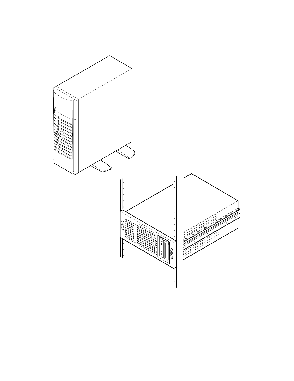
DEC01620
Typical D IGITA L S erver 3220 (Top) a nd 3220R (Bottom)

1-1
1
Introduction
1
The DIGITA L Se r ve r 3220 and 3220R are high-performance, highly-scaleable
departmental servers featuring the latest in modular processor and storage
technology. The DIGITAL Serv e r 3220 is a free-standing pedestal server, while the
DIGITAL Se r ve r 3220R is a rack-mountable server. The DIGITAL Server 3220
includes a monitor, a 104-key keyboard, and a three-button mouse. The DIGITAL
Server 3220R can be mounted into any Electronic Industries Association (EIA)
standard 19-inch rack. The rack, monitor, keyboard, and mouse must be purchased
separately. Both servers support the following features:
Reliabilit y /A v a ila bilit y
Processor Module
Support for one or two processors with 512 KB L2 cache and
the Intel BX chipset with 100 MHz bus speed.
Dual-Channel SCSI
Controller
Onboard dual-channel SCSI controller with wide Ultra internal
signaling and wide Ultra2 for external signaling on SCSI
channel 2.
Super I/O Controllers
Diskette drive, 2 serial ports, an ECP/EPP parallel port,
2-channel DMA, and IDE CD-ROM.
Power Supply
300 W power supply with server manageability.
continued

Introduction
1-2
Flexible Memory
Architecture
Server memory can be upgraded from 64 MB to a maximum
of 1 GB using 64 MB, 128 MB, or 256 MB registered SDRAM
DIMMs.
SDRAM DIMMs
168-pin registered SDRAM DIMMs, 10 or faster, with
100 MHz bus speed.
Internal Sensors
Monitors internal server temperatures, fan operation, and
voltages for the main logic board and processor module.
Clusters
Supports DIGITAL Clusters for Windows NT and Microsoft
Cluster Server (part of Microsoft Windows NT Server,
Enterprise Edition) for database and file services failover.
Server Ex pansion
Expansion Slots
Five PCI expansion slots, one shared PCI/ISA slot, and one
dedicated ISA slot.
Internal Storage
Devices
Accommodates four half-height or full-height hot swap drives,
one CD-ROM (standard), a 3½-inch diskette drive (standard),
and two half-height, 5¼-inch devices; or one full-height, 5¼inch device, such as a tape drive. The model 3220R
supports HDD/carrier in both half- and full-height units.
Hot Swap Disk
Capability
Supports up to four hot swap drives that can be replaced
while the server is operating with a RAID adapter.
Universal Serial Bus
Two integrated USB ports.
External I/O Ports
Two serial ports and one Extended Capabilities Port (ECP)/
Enhanced Parallel Port (EPP) to support external options,
such as a printer, modem, or local terminal.
continued

Introduction
1-3
External SCSI Port
Your server can be cabled to a rear panel SCSI knockout to
provide connection to an external storage box.
Integrated Video and
Network Controllers
A Video-Network (V-Net) daughter card on the main logic
board provides a video port for connecting to the S3 Trio64V2
video controller and one 10/100Base-T (10/100 Mb/s)
Ethernet port (RJ45) for connecting to the DIGITAL Ethern e t
controller.
Server Management and Security
Server Diagnostics
Allows local and remote diagnosis of server problems.
Hardware Configuration
Allows local and remote server configuration.
Unique Asset
Management
Unique server identifier in non-volatile memory provides
easy asset management.
BIOS Setup Utility
Allows configuration of your server’s factory-default
settings.
BIOS and Firmware
Upgrade Utility
Upgrades the BIOS and firmware versions.
Drive Status Indicators
(LEDs)
Provides immediate status information on hard drive
activity or failure.
Server Fault Bus and
LED Status
Provides immediate status information on server fan,
temperature, voltage, and memory failure.
Key Lock (Model 3220
only)
Limits access to server components. A 45° turn clockwise
opens the top door. A 90° rotation opens the bezel and
allows access to the side panel thumbscrews, hot swap
drives, and other components.

Introduction
1-4
Server Software and Documentation
The following software and documentation are supplied with your server:
•
ServerWORKS Manageability Suite contains ServerWORKS Quick
Launch, DIGITAL Serve rWOR KS M anager, and licenses.
−
ServerWORKS Quick Launch consists of a bootable CD-ROM disc,
a companion CD-ROM, and
Getting Started
guide. The Quick
Launch program steps you through the initial server setup and
operating system installation process.
Refer to the ServerWORKS Quick Launch Getting Started Guide and the
README.TXT file, which is located on the Quick Launch CD-ROM.
−
DIGITAL Se r ve rWOR K S M anager consists of two CD-ROMs, an
Installation and User’s Guide
, and supporting documentation.
Refer to th e D IGITAL S e rv e rWOR KS so ftw a r e ki t fo r mo r e i n fo rm a tion.
•
Server documentation box contains this
System Reference
, an
Installation Guide
, a
Documentation Overview
, Warranty information, and
Registration Card.
NOTE:
You might have order ed additional options, s uc h as
disk drives or m odem s , that have been ins talled in your
server. The documentat ion and any r elated softwar e for
these options hav e als o been pr ov ided. Save this m aterial
for future reference.

Introduction
1-5
Diagnostic Software
Diagnostic software is shipped with every DIGITAL Serve r o n th e Qu i c k Launch CDROM. This software contains an advanced set of diagnostic utilities for identifying
and correcting problems with the server. The diagnostic software is used to verify
proper hardware installation and isolate intermittent problems that are not detected by
the Power-On Self Test (POST).
The diagnostic program is a stand-alone MS-DOS package that is run from diskettes
or from the DOS partition on the server’s hard disk drive.
The diagnostic software includes:
•
AMIDiag base diagnostic (processors, memory, and main logic board
components tests) from American Megatrends, Inc.
•
DIGITAL vendor extended tests (SCSI, network, IDE, and RAID)
•
Extensive on-line help and the
AMIDiag User’s Guide
Refer to Chapter 2, “Server Software and Utilities” for information on creating
diagnostic diskettes from the Quick Launch CD-ROM.
For additional information on “When to Use the Diagnostics” and “Running the
Diagnostics”, refer to Chapter 13. Also refer to the AMIDiag User’s Guide,
located on the Quick Launch CD-ROM and to the README.TXT file on the
diagnostics diskettes.

Introduction
1-6
Server Ut ilities and Technic al Support
Current server utilities and technical support information is available on the Quick
Launch CD-ROM discs and the Internet.
For product information, use the address:
http://www.windows.digital.com
For technical support, use the address:
http://www.windows.digital.com/support/support.asp
For access directly to the software library for BIOS and driver updates, use the
address:
http://www.windows.digital/com/~ftp/00-index.stm
If you need additional information, access “Service Information” located in the
ServerWORKS Quick Launch CD-ROM discs.

2-1
2
Server Software and Utilities
2
Introduction
This chapter describes the utilities supplied with your server. Server utilities include:
•
ServerWORKS Quick Launch This software is used to install a network
operating system onto the server. The CD-ROM also contains various
device drivers and on-line documentation.
•
BIOS Setup Utility This utility allows you to configure your server after
installing additional options and when changing your server’s factory-default
settings. The BIOS Setup utility is available each time you boot your server.
•
BIOS Upgrade Utility This utility allows you to update or restore your
server’s BIOS. The BIOS Upgrade utility is available on the Internet.
•
SCSI Configuration Utility This utility allows you to configure and view
settings of the onboard SCSI controllers and SCSI devices. The SCSI
configuration utility is available each time you boot your server.
•
RAID Configuration Utility This utility is available for RAID-ready servers
only. This utility allows you to configure your RAID array and is available
each time you boot your server.
•
Diagnostics Diagnostics are used to verify server operation. The
diagnostics are available on the Quick Launch CD-ROM discs.

Server Software and Utilities
2-2
ServerWORKS Quick Launch
ServerWORKS Quick Launch is used to install the server’s Network Operating
System (NOS). In addition to providing quick and seamless NOS installation, Quick
Launch also provides device drivers, documentation, and the ability to make diskettes
of utilities such as diagnostics. For more information, refer to the
Quick Launch
Getting Started
guide.
BIOS Setup U tility
The BIOS Setup utility enables you to select and store information about your
server’s hardware and software in the battery-backed memory of the CMOS RAM.
This information takes effect each time the server boots and can be changed any
time you run setup.
You should use the BIOS Setup utility each time you need to reconfigure or expand
your server.
The following is an example of a BIOS Setup utility screen.
CAUTION:
Your server was s etup for normal oper ation at
the fact or y and will oper ate properly without additional
configuring.
It is impor tant for y ou to read carefully and under s tand this
section befor e attempting to modify your s er v er ’s factory
settings. Changing some settings might caus e y our s er v er
to operate impr oper ly .

Server Software and Utilities
2-3
Figure 2- 1 . Ty pic a l B IOS S e tup U tilit y S creen
Main Advanced Security Boot Exit
System Time: [13:11:10]
System Date: [10/29/1997]
Diskette A: [1.44 MB,3½"]
>Primary Master [Auto]
Video System: [EGA/VGA]
Monitor Type: [Color]
>Cache and Shadow
>Keyboard Features
System Memory: 640 KB
Extended Memory: 80896 KB
At Bus Space: [Disabled]
Extended Memory Report: [Compatibility]
Item Specific Help
DEC01706

Server Software and Utilities
2-4
Use the BIOS Setup utility to:
•
Set time and date
•
Change I/O port se ttings
•
Set security options
•
Change the boot sequence
•
Check system management parameters
The remainder of this section explains how to run the BIOS Setup utility, maneuver
through the options, and perform specific tasks.
Accessing the BIOS Setup Utility
To access the BIOS Setup utility:
1. Turn on your server and allow the Power-On Self Test (POST) to complete.
2. Make a note of any configuration errors listed, and then press [F2] to display
the Main menu.
3. Follow the instructions on your monitor screen and any on-line help pop-up
screens to configure your server.

Server Software and Utilities
2-5
Helpful Hints
When using the System Setup (F2) in the BIOS Setup utility:
•
Several keyboard keys are assigned to help you select menus and submenus, options, change option values, and display help information. These
keys are displayed at the bottom of all menus as follows:
Key Function
F1 Help (provides a general help screen)
Esc Exit (Exits the Setup utility and exits sub menus within the Setup utility)
↑↓
arrow keys Select Item
← →
arrow keys Select Menu
-/+ or spacebar Change Values
Enter Select > Sub-Menu
F9 Setup Defaults (Restore all current Setup screen values to their factory
default settings)
F10 Save and Exit
•
Item-specific help is available anytime during the setup process and appears
at the right of the setup screen when an option is highlighted.

Server Software and Utilities
2-6
•
Choosing the “
Exit
” menu allows you to:
−
Select “
Save Changes & Exit
” to save all Setup values and exit
Setup.
−
Select “
Exit Without Saving Changes
” to exit Setup without
recording any changes.
−
Select “
Get Default Values
” to set all setup options to their
factory default values.
−
Select “
Load Previous Values
” to restore all setup values from
the last session.
−
Select “
Save Changes
” to save all setup selections without exiting
Setup.
Changing Your Server’s Configuration
The following sections provide detailed information on changing your server’s factory
configuration. Before changing any setting, make sure you fully read and understand
the information provided and view any on-line help for a selected setting.
Changing Time and Date
To change the time and date:
1. Reboot the server.
2. Press <F2> when the DIGITAL logo screen appears.
3. In the Main menu, using the cursor keys and [Tab], select (highlight) the
System Time or System Date field you want to change.
4. Use [+] or [-] to change the field to the desired value.
You can also enter the desired date and time by typing the required
numbers.
5. Press [Esc] then [Enter] twice to exit the BIOS Setup utility and to reboot the
server so changes immediately take effect.

Server Software and Utilities
2-7
Changing I/O Port Settings
The following list shows the settings that can be made to the I/O ports via the
Advanced
section of the BIOS Setup utility.
•
PS/2 mouse
•
COM1
•
COM2
•
Parallel port
•
Parallel port mode
•
Floppy disk controller
•
Integrated PCI Ethernet
•
Integrated PCI SCSI
•
Integrated IDE controller
For more information on changing I/O port settings, refer to Appendix C, “BIOS
Setup Utility Features.”
To change the I/O port settings:
1. Reboot the server
2. Press <F2> when the DIGITAL logo screen appears.
3. Select
Advanced.
4. Select
Integrated Peripherals.
5. Select the port(s) you wish to change.
6. Use the +/- keys to change values.
7. Press [Esc] then [Enter] twice to exit the BIOS Setup utility and to reboot the
server so changes immediately take effect.

Server Software and Utilities
2-8
Assigning IRQs
The following information is important for managing server IRQ assignments.
The default setting for PCI expansion boards is Auto Select, which automatically
assigns IRQs to PCI expansion boards. If you have ISA expansion boards or you
wish to manually control PCI IRQ assignments, you must do the following to assign
IRQs to expansion slots.
1. Reboot the server and press <F2> when the DIGITAL logo screen appears.
2. Select
Advanced
at the top of the screen menu.
3. Select
PCI Configuration.
The following table shows the menu
selections.
Advanced
Menu Fields Settings Comments
PCI Configuration: [submenu]
PCI IRQ line #
Disabled
Disables the specific IRQ Line number.
Auto select
(1)
Automatically assigns IRQs to PCI slots.
3
4
5
7
9
10
11
12
14
15
Select a number to assign to the PCI IRQ line. If the
IRQ number is already in use, an asterick (*) appears
to the left of the line.
PCI/PNP ISA UMB Region Exclusion
Use this selection to reserve a specific block of upper
memory for ISA adapters. Press [Enter] to display
memory addresses available.
PCI/PNP ISA IRQ Resource Exclusion
Use this selection to reserve IRQ numbers for ISA
adapters. Press [Enter] to display IRQs.
(1)
Factory default

Server Software and Utilities
2-9
Setting Up Security
The following sections describe the security features available and how to use them.
Setting Supervisor and User P asswords
Your server has password protections that can be set to prevent unauthorized
access to the BIOS Setup utility. If a supervisor password is set, the server prompts
you to enter a password before accessing the BIOS Setup utility.
If "Password On Boot" is enabled, and both the supervisor and user passwords have
been set, you need to enter either the supervisor or user password to use the server.
The following list provides more information about setting passwords.
•
You must enable the password during boot.
•
Setting the supervisor password allows you to make changes to the boot
process.
•
Setting the user password allows a lower level user to access files.
NOTE:
A supervisor pas s wor d m us t be set befor e y ou c an
set a user pass wor d. If t he s uper v is or pas s wor d is later
deleted, the us er pas s wor d is automatically r em ov ed.

Server Software and Utilities
2-10
Perform the following steps to set a supervisor password:
1. Reboot the server and enter Setup.
2. Highlight the “
Security
” menu.
3. Highlight “
Set Supervisor Password
” and press [Enter].
4. Type in a seven (7) digit alpha-numeric supervisor password and then press
[Enter].
5. Retype your password as instructed and press [Enter]. (Notice that
“Supervisor Password Is” field now indicates Enabled.)
If desired, set a user password as follows:
1. Highlight “
Set User Password
” and press [Enter].
2. Type in a seven (7) digit alpha-numeric user password and then press
[Enter].
3. To confirm, retype the user password as instructed and press [Enter].
(Notice that “User Password Is” field now indicates Enabled.)
4. Press [Esc] then [Enter] twice to exit the BIOS Setup utility and to reboot the
server so changes immediately take effect.
The server runs the POST and then asks for the password, which has just been set.

Server Software and Utilities
2-11
Enabling Password On B oot
When “Password On Boot” is enabled, a screen appears after POST. The screen
asks you to enter your supervisor or user password to allow your server to finish the
boot process.
Perform the following steps to set “Password On Boot”:
1. Reboot the server and enter Setup.
2. Highlight the “
Security
” menu.
3. Highlight “
Password On Boot
.”
4. Press the [+] key. (Pressing the [+] key again reverses your action.)
5. Press [Esc] then [Enter] twice to exit the BIOS Setup utility and to reboot the
server so changes immediately take effect.
Eliminating User and Supervisor Passwor ds
To eliminate your server’s password(s):
1. Reboot the server and enter Setup.
2. Enter the supervisor password and press [Enter].
3. Do you wish to eliminate the User Password or the Supervisor Password?
If User Password, select “
Set User Password
.”
If Supervisor Password, select “
Set Supervisor Password
.”
4. Press [Enter] three times.
You have cleared the old password and are returned to the “Security” menu.
Verify that the appropriate password is disabled by checking “
User
Password is
” or the “
Supervisor Password is
” field, whichever is
relevant.
5. Press [Esc] then [Enter] twice to exit the BIOS Setup utility and to reboot the
server so changes immediately take effect.

Server Software and Utilities
2-12
Other Security Options
These options can provide further security for your server under certain conditions:
•
If “Password On Boot” is enabled and “Diskette Access” is set to
“Supervisor,” entering the supervisor password at boot allows access to a
diskette. Entering the user password at boot, however, prevents the server
from accessing a diskette.
CAUTION:
Consider your secur ity needs caref ully before
using the Passwor d on B oot option. W hile this option is
enabled, the cont ents of the har d dis k dr iv e c annot be
backed up to diskettes and the s er v er c annot be booted
from a diskette drive.
•
Sign On Banner
When enabled, allows a custom banner to be displayed
every time you turn your server on.
•
Diskette Access
While enabled, this option prevents the server from
accessing a diskette.
•
Network Server
Locks the keyboard and mouse to prevent tampering
during network operation. You must enter a supervisor password to unlock
the keyboard and mouse.
•
System BIOS Flash
When disabled, prevents the server’s BIOS from
being flashed (rewritten).

Server Software and Utilities
2-13
Changing the Boot Sequence
It is sometimes necessary to change your server’s boot sequence. Follow your
network manual’s instructions to determine the correct boot sequence.
To change the boot sequence, proceed as follows:
1. Reboot the server and enter the BIOS Setup utility.
2. Highlight the “
Boot
” menu.
If the CD-ROM drive is listed as the first boot device in the BIOS, the server
will boot from the CD-ROM drive. Otherwise, the server can be booted from
the diskette drive (drive A) or the hard drive (drive C). If the diskette drive
(drive A) then the hard drive (drive C) is selected, the server searches the
diskette drive (drive A) first to boot the operating system. When no diskette
is in the diskette drive (drive A), the server then tries to boot from the hard
drive (drive C).
3. Use the [↑] and [↓] arrows to locate the field you want to change. Then use
the [+] to raise the order and [-] to lower it.
4. Press [Esc] twice then [Enter] twice to exit the BIOS Setup utility and to
reboot the server so changes immediately take effect.
Following is a typical boot sequence:
•
CD-ROM
•
Diskette drive (drive A)
•
Hard drive (drive C)
For more information, refer to the “Server Scan Sequence” section in Chapter
10.

Server Software and Utilities
2-14
Speeding up the Boot Process
There are four options for speeding up the boot process which, in essence, eliminate
or replace displays or checks. To make these changes, proceed as follows:
1. Reboot the server and enter Setup.
2. Highlight the
Boot
menu.
The following table lists and describes the items displayed.
Field Description
Floppy check Verifies the diskette boot drive.
Setup prompt Displays the Setup prompt message during the boot
sequence. If disabled, the Setup prompt message will not be
displayed; however, you can still access the BIOS Setup
utility by pressing <F2> before POST completes.
POST errors Pauses and displays the Setup prompt or Resume boot
prompt, if an error occurs during the boot sequence. If
disabled, the server always attempts to boot.
Sign-on banner When enabled, displays the DIGITAL logo during POST.
3.
Select the item(s) you wish to change and use the [+] or [-] as follows:
Field Speed Up Boot Selection
Floppy check Disable
Setup prompt Enable
POST errors Disable
Sign-on banner Disable
4. Press [Esc] twice then [Enter] twice to exit the BIOS Setup utility and to
reboot the server so changes immediately take effect.

Server Software and Utilities
2-15
Checking System Management Parameters
These screens allow you to see an overview of your server's system and
environment parameters, and details of the system assets (environment, memory,
POST system, processor module, main logic board, and PCI IRQ assignment). To
manage the system:
1. Reboot the server and press <F3> when the DIGITAL logo screen appears.
2. The "Summary” menu appears. Use the [←] and [→] arrows to select the
parameter you want to view or change.
3. In screens that are editable, use the [↑] and [↓] arrows to select the field you
want to change. Enter the new parameter(s) and then press [Enter] to
accept the changes.
4. Press [Esc] then [Enter] to exit system management and reboot the server
so changes immediately take effect.
BIOS Upgrad e Ut ility
All servers have BIOS software in a flash (ROM) chip located on the main logic
board. This BIOS initializes hardware and boots the operating system when the
server is turned on. The BIOS also provides access to other services such as a
keyboard and disk drives.
You can upgrade your server's BIOS to future releases by executing the BIOS
upgrade utility (PHLASH.EXE) located in the BIOS upgrade kit. PHLASH.EXE and
BIOS upgrades are available on the Internet.

Server Software and Utilities
2-16
For technical support, use the address:
http://www.windows.digital.com/support/support.asp
For access directly to the software library for BIOS and driver upgrades, use the
address:
http://www.windows.digital/com/~ftp/00-index.stm
CAUTION:
A crisis rec ov er y dis k ette should be created
before upgrading the s er v er B IOS.
Also, when upgrading the BIOS, you must remove any video
expansion boards and enable the onboard VGA. In the rare
event that you might need to use the Crisis Recovery Diskette,
the server will require that the onboard VGA be used in this
mode.
Two switches and one BIOS option affect the result of executing the PHLASH.EXE
program:
1.
BIOS Protection (SW1-1
) — This switch, located on the main logic board,
must be s e t to
Normal
before you can upgrade the server’s BIOS.
2.
Recovery Mode Switch (SW1-2)
— This switch, located on the main logic
board, must be set to
Recovery
so the server BIOS can enter “Recovery
Mode.”
3.
System BIOS Flash (BIOS option)
— This BIOS option must be set to
Enabled
before you can upgrade the server’s BIOS.
If you are having trouble flashing your server’s BIOS, refer to Chapter 13,
“Troubleshooting.”

Server Software and Utilities
2-17
SCSI Configurat ion Utilit y
Your D IGITA L Se rv e r c o me s w i th a n onboard, dual channel SYMBIOS 896 SCSI
controller and a SCSI
Configuration utility. This utility, located within the server BIOS,
allows you to change SCSI controller settings without opening the server.
Use the SCSI Configuration Utility to:
•
Check global factory default settings for each SCSI channel and devices
connected to it.
•
Change factory default settings for individual SCSI devices.
•
Change the device boot order.
To start the SCSI Configuration utility:
Press [Ctrl] + [C] when the following message appears during the boot process:
Press Ctrl-C to start Symbios Configuration Utility…
This message stays on the screen for about five seconds. If you invoke the
Configuration utility, the Main Menu of the Symbios SCSI Configuration utility is
displayed.
Main Menu
DEC01598
Port IRQ---------Status-------------NVRAM
SYM53C896 9000 9 On On Yes
Additional Adapter Configuration
Display Mode = Verbose
Mono/Color
Language
Num Level Current Next-Boot Found
SYM53C896 9400 9 On On Yes
Change Adapter Status
Adapter Boot Order
Help
Quit

Server Software and Utilities
2-18
The Main menu fields are described in the table that follows.
Menu Fields Allows you to…
SYM port number Change adapter setup specifications and device selections.
Change adapter status Activate or deactivate an onboard or external SCSI channel and all devices
attached to it. The changes take place after a reboot.
Adapter boot order Change the boot sequence of the adapters in the server.
Additional adapter
configuration
Select adapters other than those displayed on the first screen.
Display mode
Select a Verbose or a Terse text.
Mono/Color Change the screen instantly between
Mono and Color.
Language
Select a language for th is utility.
Determining Devices Attached to Each SCSI Channel
To check the devices connected to each channel, use the following procedure:
1. Start the Symbios SCSI Configuration utility to display the Main menu.
2. Use the arrow keys to select the SYM port number and press [Return]. The
following menu items are displayed:
Adapter Setup
Device Selections
Help
Exit this menu
3. Choose
Device Selections
to display the SCSI devices attached to this
port.
4. Press the [
Esc
] key to exit from this menu.
For additional information, refer to the Symbios User’s Manual on the Quick Launch
CD-ROM discs. Select the “User Documentation” button.

Server Software and Utilities
2-19
RAID Conf iguration U tility
If a RAID adapter is installed in the server, the RAID configuration utility appears
when you boot your server. If desired, you can skip this utility, or use this utility to
configure your RAID array during initial setup.
Refer to the RAID User’s Manual on the Quick Launch CD-ROM discs. Select
the “User Documentation” button.
Diagnostics
Diagnostic software is shipped with every DIGITAL Server o n th e Qu i ck Launch CDROM discs. This software contains an advanced set of diagnostic utilities for
identifying and correcting problems with the server. The diagnostic software can be
used to verify proper hardware installation and isolate intermittent problems that are
not detected by the Power-On Self Test (POST).
The diagnostic program is a stand-alone MS-DOS package that can be run from
diskettes or from the DOS partition on the server’s hard disk drive.
To access the supplied diagnostic software:
•
During your server installation process, the diagnostic software will be
automatically copied to a subdirectory on the Quick Launch MS-DOS
partition (only if you selected the option to create a partition). This allows
you to run the diagnostic software from the MS-DOS partition you created.
•
Using the Quick Launch CD-ROM, you can create bootable diagnostic
software diskettes. This allows you to run the diagnostic software using the
diskettes you created.
NOTE:
DIGITAL strongly recommends that you copy the
diagnostics t o dis k ettes and then us e these diskettes to run
the diagnostics on y our s er v er .
To run the diagnostics from the DOS partition, perform the following:
1. At the MS-DOS prompt, type:
C:\diag\diagnose.bat
2. After the server boots, choose MS-DOS from the boot selection.
3. Once the diagnostics begin, the main screen appears.

Server Software and Utilities
2-20
To create the diagnostic diskettes from the Quick Launch CD-ROM, perform the
following:
1. Insert the Quick Launch CD-ROM into the drive and boot the server; or from
a PC or workstation, use Windows File Manager or Explorer and run:
<cd-rom>:\QLAUNCH.EXE.
2. From the Quick Launch main menu, select
Installations &
Utilities
.
3. Select the
Utilities
tab and then select the server model.
4. Insert a blank MS-DOS formatted diskette into drive A and select
Diagnostics
.
5. Select
Continue
. Afterwards, remove the diskette for safekeeping.
6. Choose the next diagnostic diskette from the list and then select
Continue
.
Create all the diskettes labeled “
Diagnostics
.”
Refer to Chapter 13, “Troubleshooting,” for more information on using the
diagnostics software.

3-1
3
Server Components
3
Introduction
This chapter shows the location of your DIGITAL Server’ s i n te rnal components and
procedures for unlocking and removing the access panels. A procedure for installing
a new Real-Time Clock (RTC) battery is also included.
Disconnecting External Devices and Power
Before removing any access panel, perform the following:
1. Shut down any applications that are currently running, then shut down the
operating system.
2. Turn off power to all external devices connected to the server.
3. Turn the server off.
4. Unplug the power cord from the power source.

Server Components
3-2
Unlocking the Server (Model 3220)
1. Unlock the server’s front bezel by depressing and rotating the key 90°
clockwise.
2. Swing the bezel open.
Keylock Function
•
Depress and rotate the key 45° for access to the control panel and upper
drive bays.
•
Depress and rotate the key 90° for access to the side panel thumbscrews
and hot swap drives.
CAUTION:
Keep your keys in a s afe place. They ar e not
easily duplicated or r eplac ed.
Removing the Front Bezel
The front bezel is the hinged door running the full height of the server. If necessary,
you can remove the front bezel by lifting it up and away from the chassis.

Server Components
3-3
Figure 3- 1 . Fr ont-Access Security Door and Front Bezel Lock

Server Components
3-4
Removing and Installing the Side Panel (Model 3220)
1. Loosen the two thumbscrews that secure the side panel to the chassis.
2. Slide the side panel to the rear of the server and then pivot it down to
remove it.
DEC01627-2
Figure 3- 2 . Removing the D IGITA L Server 3220 Side Panel

Server Components
3-5
To install the side panel.
1. Pivot the side panel up and then slide it to the front of the server.
2. Secure the side panel to the chassis using the two thumbscrews.
3. Close and lock the server’s front bezel.
DEC01627-3
Figure 3- 3 . Ins ta lling the D IGITA L S erver 3220 Side Panel

Server Components
3-6
Removing the Server from the Rack (Model 3220R)
You must remove the server from the rack prior to accessing internal components.
To remove the server:
1. Remove the front bezel (see Figure 3-4).
2.
Remove all cabling from the server.
3.
Disconnect the cable management arm from the server (see Figure 3-5).
DEC01457
Figure 3- 4 . Removing the Server from the Rack

Server Components
3-7
4.
Remove the two screws securing the server to the rack and then slide it out
(see Figure 3-4).
5.
Place the server on a flat surface.
DEC01658
Figure 3- 5 . D is c onne c ting the C a ble M a na gement Arm

Server Components
3-8
Removing and Installing the Top Cover (Model
3220R)
To remove the top cover, perform the following:
1. Remove the front bezel.
2. Remove the screw securing the top cover to the server’s chassis.
3. Carefully slide the top cover toward the rear of the chassis until the locking
tabs are clear from their slots.
4. Carefully lift the top cover up and then forward until it clears the chassis.

Server Components
3-9
DEC01627B
Figure 3- 6 . Removing the D IGITA L Server 3220R Top C ov e r

Server Components
3-10
To install the top cover.
1. Carefully slide the top cover onto the server’s chassis making sure that all
locking tabs fit into their slot openings.
2. Slide the top cover forward to secure the locking tabs into their slots.
3. Secure the top cover to the chassis using the previously removed screw.
4. Align the front bezel and then snap it into place.

Server Components
3-11
DEC01627A
Figure 3- 7 . Ins ta lling the D IGITA L S erver 3220R Top C ov e r

Server Components
3-12
Front View
Figure
Legend
Component
A Power button
B Power indicator
C Disk drive activity indicator
D 3½-inch diskette drive
E IDE CD-ROM drive
F Front access 5¼-inch half-height drive bays
G
(1)
Fault status LED label (model 3220 only)
H Removable media access door (model 3220 only)
I Front bezel
J Stabilizing feet (model 3220 only)
K Hot swap drive LED status indicators
L Three-way security lock (model 3220 only)
M
(2)
Fault status LEDs
N Reset button
(1)
For the model 3220, the fault status LED label is located at the back of the removable media access door.
For the model 3220R, this label is located behind the front bezel at the lower-left corner of the chassis.
(2)
For the model 3220 only, the four internal fault status LEDs appear as one indicator with the front door
closed. You must open the front door to view a specific LED fault code.

Server Components
3-13
E
D
F
L
H
A
N
I
C
M
B
K
G
J
M
N
A
B
D
FE
C
DEC01621-2
KI
4
3
2
1
Figure 3- 8 . D IGITA L Server 3220/3220R Front View

Server Components
3-14
Internal View
Figure
Legend
Component
A Video/Ethernet daughter card
B Hot swap drive bay cooling fan (model 3220 only)
C Power supply
D Removable media drive bays
E Hot swap drive bay
F Main logic board cooling fan
G Speaker
H Main logic board
I Processor and memory module with retainer

Server Components
3-15
Model 3220
Side View
Model 3220R
Top View
H
F
D
E
C
DEC01675-2
G
I
A
B
A
C
E
D
F
G
H
I
Figure 3- 9 . D IGITA L Server 3220/3220R Internal View

Server Components
3-16
Rear View
Figure
Legend
Component
A One dedicated ISA expansion slot
B One shared ISA/PCI expansion slot
C Five dedicated PCI expansion slots
D USB ports
E Serial ports
F Keyboard and mouse ports
G Video port
H 10/100Base-T connector (RJ45)
I SCSI knockouts
J ac power input plug
K Voltage selection switch
L Parallel port
M Security hold-down bar (model 3220 only)
N Cable management arm attachment holes (model 3220R only)

Server Components
3-17
KJ
I
H
G
F
L
E
D
C
B
A
I
M
ABCDEFGH
J
K
L I
N
DEC01623-2
Figure 3- 1 0 . D IGITA L Server 3220/3220R Rear View

Server Components
3-18
Main Logic Board Connectors
Figure Legend Connector
A Dedicated ISA expansion slot (slot 2)
B Shared PCI/ISA expansion slots (PCI slot 6; ISA slot 1)
C PCI expansion slots (slots 1-5)
D USB ports
E Two serial ports and one parallel port
F Mouse and keyboard ports
G Video/Ethernet daughter card connector
H OCP Connector (for model 3220R)
I Fan 2 connector (for model 3220 hot swap drive bay)
J Power supply connectors
K Diskette drive connector
L IDE connector for CD-ROM drive
M Channel 1 SCSI connector
N
(1)
Channel 2 SCSI connector
O Processor and memory module connector
P RSM connector
Q Hard disk drive LED connector
R Speaker connector
S Fan 1 connector
(1)
If a dual processor module is installed, this connector is hidden.

Server Components
3-19
1
2
3
1
2
4
5
6
A
B
C
D
E
K
J
N
P
O
M
L
Q
G
F
I
R
S
DEC01624-2
H
Figure 3- 1 1 . Ma in Logic B oa r d C onne c tor s

Server Components
3-20
Main Logic Board Components
Figure Legend Component
A Real-time clock battery
B SCSI controller
C Switch block (SW1)
D BIOS flash ROM

Server Components
3-21
1
2
3
1
2
4
5
6
D
C
A
B
DEC01624-3
Figure 3- 1 2 . Ma in Logic B oa r d C om pone nts

Server Components
3-22
Processor Module Components
Figure
Legend
Component/Connector
A Processor 1
B Processor 2 slot or terminator card
C Switch for processor clock speed settings
D Four DIMM sockets

Server Components
3-23
DEC01638-3
A
BC
D
1
2
Figure 3- 1 3 . Pr ocessor Module C om pone nts

Server Components
3-24
Video/Ethernet Daughter Card Connectors and
Indicators
Figure
Legend
Connector
A Video graphics port
B Network link indicator (green)
C Network activity indicator (yellow)
D 10/100Base-T connector (RJ45)
DEC01625-2
ABC
D
Figure 3- 1 4 . Vide o/E the r ne t D a ught e r Card Connectors

Server Components
3-25
Tools Needed
Prior to installing an option, have the following available:
•
A Phillips screwdriver
•
An antistatic wrist strap
Static Electricity
Static electricity collects on non-conductors such as paper, cloth, or plastic. A static
discharge can be damaging even though you often cannot see or feel it. To prevent
damage to circuit boards and/or components:
•
Before touching any circuit board or component, put on a properly-grounded,
anti-static wrist strap.
•
Keep circuit boards and components away from non-conductors.
•
Keep clothing away from circuit boards and components.
•
Keep circuit boards in anti-static bags.

Server Components
3-26
Replacing the Real Time Clock (RTC) Battery
Your server’s battery runs the server clock and retains any setup information when it
is turned off. If your serve r e v e r fails to retain the correct date, time, or configuration
settings when it is turned on, you need to replace your server’s RTC battery. Also,
make sure you replace the battery with either a DIGITAL part numb e r 1 2 -41474-05,
Toshiba (P/N CR2032), or equivalent 3 V dc Lithium battery. This part can be
obtained through your DIGITAL ser vi c e p ro v ider.
WARNING:
There is a danger of battery explos ion if a lithium
battery is inc or r ec tly replaced. To prevent damage to your
server, be s ur e the + side fac es up when ins talling a new
battery.
Depending on your locality, your server ’s battery might be
considered hazardous was te. Make sur e y ou follow any stat e
or local stat ute to properly dis pos e of the old batt er y .
To replace the battery/RTC, perform the following:
1. If you have not already done so, record server configuration settings using
the BIOS Setup utility.
2. Turn off your server.
3. Disconnect external devices (if any), ac power, and monitor power.
4. For th e D IGITAL S e rve r 3220 only, unlock and open the front bezel, loosen
the two thumbscrews, and then remove the side panel (see Figure 3-2).
5.
For the D IGITAL S e rve r 3220R only:
a. Remove the front bezel (see Figure 3-4).
b. Disconnect all cables from the rear of the server.
c. Disconnect the cable management arm (see Figure 3-5).
d. Remove the two screws securing the server to the rack and then
slide it out (see Figure 3-4).
e. Remove the top cover (see Figure 3-6).

Server Components
3-27
6.
Lift the retaining clip slightly and push on the battery from the side to slide it
out (see Figure 3-15).
1
2
3
1
2
4
5
6
DEC01624-4
Figure 3- 1 5 . R e pla c ing the S erver Battery/RTC

Server Components
3-28
7. Install the new battery/RTC (Figure 3-15). When installing the new battery,
make sure the “+” side faces up.
8. For th e D IGITAL S e rve r 3220 only, replace the side panel and then close
and lock the front bezel (see Figure 3-3).
9.
For the D IGITAL S e rve r 3220R only:
a. Replace the top cover (see Figure 3-7).
b. Slide the server into the rack and then secure it using the two
previously removed screws (see Figure 3-4).
c. Connect the cable management arm (see Figure 3-5).
d. Replace the front bezel (see Figure 3-4).
e. Connect any previously removed cables to the rear of the server.
10. Restore power, reboot and then run the BIOS Setup utility to configure your
server.
Refer to Chapter 2, “Server Software and Utilities,” for information on using the
BIOS Setup utility.

4-1
4
Server Management
4
Introduction
The DIGITA L Se r ve r 3220/3220R is configured with hardware that supports server
management, including an 8031 processor with multiple I
2
C busses for server status
reporting.
Managing Your Server
The server allows you to perform the following management functions:
•
Monitor main logic board voltage and cooling fan status
•
Monitor processor module voltage, temperature and status
•
Detect and automatically correct single-bit ECC errors
The DIGITA L Se r ve r 3220/3220R allows you to manage your server and its main
components by:
1. Obtaining information about the main logic board and the processor module.
2. Notifying you of any changes to the main logic board or processor module
on your server.
Information can be obtained either through the BIOS Setup utility or through system
management software, such as the DIGITAL Server WOR KS Manager.

Server Management
4-2
Obtaining Information about Your Server
The DIGITA L Se r ve r p r o v ides the following system information for the main logic
board and the processor module configured on your server:
•
Asset number User-definable field for tracking these components
•
Part number DIGITAL p a rt n u mb e r
•
Revision number Board assembly revision number
•
Serial number Serial number of the board assembly
•
Artwork number Revision of the printed circuit board
The System ID is also located on the main logic board and processor module. The
System ID contains the following information:
•
Model number Server model number
•
Serial number Server serial number
•
System asset number User-definable field for tracking the system

Server Management
4-3
The main logic board and processor module each contain memory where specific
information and System ID information is stored. The main logic board also stores
the server’s System Asset number (see Figure 4-1).
Information is available for the server’s main logic board and processor module (such
as part numbers, revisions, serial numbers, etc.). You can also assign Asset
numbers to these components. In addition, the software can detect when you
change your server configuration by adding or removing either component.
You can obtain information about your server’s configuration by running the BIOS
Setup utility or by using the ServerWORKS management software.
DEC0103
Processor Module
Main Lo
g
ic Board
Asset#
Part#
Revision#
Serial#
Artwork#
System ID
Asset#
Part#
Revision#
Serial#
Artwork#
System
System ID
DIGI TAL
3220/3220R
Server(System ID)
Figure 4- 1 . D IGITA L Server Component Inf ormation

Server Management
4-4
Obtaining Information Using the BIOS Setup Utility
You can use the BIOS Setup utility to check the Serial number, Revision number,
and Asset number for the main logic board and processor module configured in the
server. For example, if you change the main logic board or processor module in
your server, you must run the BIOS Setup utility to re-synchronize the System ID
(server model number and serial number) in the main logic board or processor
module’s memory. The BIOS Setup utility will check the new main logic board or
processor module and will then detect the System ID mismatch.
You can view the details for the main logic board or processor module by pressing
<F3> and then selecting the
SYS
option. The BIOS Setup utility lists the server
model number and server serial number information stored on the main logic board
or processor module. You can then confirm the correct model number and serial
number. This data is available on the label located on the server’s back panel.
Refer to Appendix C, “BIOS Setup Utility Features,” for more detailed
information about the BIOS Setup utility.
Obtaining Information Using Server Management Software
Your D IGITA L Se rv e r i s s hipped with DIGITAL Se r ve r WOR KS Manager software.
ServerWORKS Manager is a workgroup and server management product for
DIGITAL’ s fa m i l y o f s e rve r s. S e rv e rWOR K S M anager utilizes the Simple Network
Management Protocol (SNMP) environment to assist the Network or Server
administrator by constantly monitoring the network for problems.
DIGITAL Se r ve rWOR K S M anager is based on an open architecture that enables
seamless integration and interoperability with popular enterprise management
software packages such as Computer Associates’ POLYCENTER
Manager/NetView, Hewlett-Packard’s OpenView UX for Windows, and IBM’s
Netview/6200 AIX. Also included with the DIGITAL ServerWOR K S M anager are
Network Operating System (NOS) Agents for Windows NT V4.x, Novell NetWare
V3.12, V3.2, and V4.x, and SCO UNIX V5.x. The OS/2 NOS includes its own agent
and can also be managed from ServerWORKS Manager.

Server Management
4-5
DIGITAL Se r ve rWOR K S M anager allows the Network or Server Administrator to
perform the following functions on your server:
•
Manage DIGITAL PC p ri n t, file, and application servers supported by
DIGITAL Se r ve rs u s ing a Windows-based graphical user interface (GUI) for
point and click simplicity.
•
Display server component information that provides critical information such
as processor and file system utilization and information about the network
interface.
•
Automatically build a database of the network by Autodiscovering all SNMP
network resources and display the nodes discovered during Autodiscovery
on a color-coded topological map.
•
Poll all network devices at intervals defined by the administrator.
•
Perform an in-depth network analysis to continuously monitor the status of
the network.
•
Set alarms and alerts for specified events on all network devices, as well as
the network itself, to spot problems early and avoid costly downtime.
Refer to th e D IGITAL S e rv e rWOR KS M anager Installation and User’s Guide for
more information on how to use ServerWORKS Manager to view and be notified
of events on the server.
You can also manage the DIGITAL Server w i th o th e r SN M P- b a se d m anagers.
Refer to th e D IGITAL S e rv e rWOR KS M anager Installation and User’s Guide for
more information.

Server Management
4-6
Displaying Server Status Using the Hardware
There are two types of information displayed when your DIGITAL Serve r i s operating:
•
Normal status messages
•
Error messages
During normal operation, Power On Self Test (POST) and boot messages are
displayed on the monitor. Some error messages are also displayed by the server
fault status LEDs.
These messages can also be seen by using the DIGITAL Ser ve rWOR K S M anager
to monitor the server.
Refer to Appendix A for server fault status LED and POST messages.

5-1
5
Processor Upgrades
5
Introduction
Installing a second processor increases the capabilities of your DIGITAL Server
3220/3220R. This chapter describes the configuration guidelines that must be
followed prior to upgrading your server as well as detailed procedures on removing
and installing a processor module.
Processor Configuration Guidelines
To upgrade to a dual processor configuration you must purchase and install a
processor upgrade kit. Contact your authorized DIGITAL sales representative for
more information.
Apply the following guidelines to your processor upgrade:
•
Single processor modules must be installed in the primary processor socket
(CPU1) and have a termination card installed in the second processor
socket (CPU2). The termination card must be removed prior to installing a
second processor.
•
If two processor are installed, they must be the same speed.
•
DIGITAL re c o mm ends that dual processor configurations use processors
with identical stepping (manufacturing revision). Processors with different
stepping might not function properly. You can use the processor ID number
that appears during the Power-On Self Test (POST) for each processor to
help you determine stepping. This information is found in the README files
on the Quick Launch CD-ROM discs.

Processor Upgrades
5-2
•
Use only DIGITAL-supplied processor modules and DIMMs.
•
Use an anti-static wrist strap when servicing any part of the server.
Refer to Appendix A, “Technical Specifications” for specific POST messages.
Please refer to the README file on the ServerWORKS Quick Launch CD-ROM
discs to view the latest processor compatibility information. Also, contact your
DIGITAL sales representative or reseller for future processor upgrades and
BIOS revisions.
Removing the Processor Module
To remove the processor module:
1. Power down the server.
2. Disconnect ac power and monitor power.
3. Remove the side panel or top cover to access the processor module.
Refer to Chapter 3, “Server Components,” for more information.
4. Place the antistatic wrist strap on your wrist and connect the grounding clip
to a non-painted metal surface of the server’s chassis.
5. Loosen the screw (A, Figure 5-1) and then remove the retainer.
6. Pull the processor module straight out of its socket.

Processor Upgrades
5-3
A
A
DEC01659-2
Figure 5- 1 . Removing the Pr ocessor Module

Processor Upgrades
5-4
Removing the Terminator Card
To remove the terminator card from the processor module, grasp the terminator by
each end and pull up (see Figure 5-2).
DEC01638-4
Figure 5- 2 . Removing the Te r m ina tor M odule

Processor Upgrades
5-5
Installing a Second Processor
1. Remove the processor from its shipping container.
2. Insert the processor into this slot (see Figure 5-3).
3. Press down on the processor so the two plastic tabs at each side lock it
securely in the socket.
DEC01638-5
Figure 5- 3 . Ins ta lling the S e c ond Pr ocessor

Processor Upgrades
5-6
Installing the Processor Module
1. If you are changing processor speeds, set all appropriate switch settings on
the processor module. Otherwise, current switch settings apply.
Refer to Appendix A, “Technical Specifications,” for switch locations.
2.
If you are installing additional memory as part of this procedure, refer to
Chapter 6, “Installing Additional Memory,” for more information.
3. Install the processor module.
4. Install the retainer and then tighten the thumbscrew (A, Figure 5-4).
5. Replace the side panel or top cover.
Refer to Chapter 3, “Server Components,” for more information.
6.
Connect all external devices and restore power. Afterwards, your server
automatically recognizes both processors.

Processor Upgrades
5-7
A
A
DEC01659-3
Figure 5- 4 . Ins ta lling the P r ocessor Module

Processor Upgrades
5-8
Run the System ID Configuration Utility
If you upgraded your server with a new processor, you need to run the System ID
utility (SIDUTIL) to store the new model information in your server memory. To run
the SIDUTIL:
1. Insert the bootable Quick Launch CD-ROM disc in the CD-ROM drive.
2. Select the
Installation and Utilities
button on the main screen.
3. Select the
Utilities
tab.
4. Insert a blank formatted diskette into drive A.
5. Select the
System Identification Utility
and then select
Continue
.
6. After creating the diskette, exit Quick Launch.
7. From drive A, run
SIDUTIL
.
Example:
A:\>SIDUTIL
8. Using the arrow keys, highlight the correct server model name/part
number/description for your server. Match the processor type and cache size
with the line items displayed to select the new DIGITAL Server m odel.
The System ID Configuration Utility appears on your monitor screen.
The description of the System ID information currently on the main logic board
appears at the first line in the following format:

Processor Upgrades
5-9
Example:
DIGITAL Se r ve r 3225 FR-B4BAW-AA
where 3225 is the model name and FR-B4BAW-AA is the part number.
The following description is an example: 400/512 PII 64 MB.
9. After selecting the correct description, press [Enter]. A new System ID is stored
in the main logic board memory. The changed model name and part numbers
appear at the top of the menu in the current field.
10. To exit SIDUTIL, press [Esc].

6-1
6
Installing Additional Memory
6
Introduction
Your server supports 168-pin DIMM memory modules that use registered
Synchronous Dynamic Random Access Memory (SDRAM) technology. Your server
requires at least 64 MB of memory. Adding more memory enables your server to run
larger, more complicated software and run it more quickly. Registered SDRAM
DIMMS are available in 64 MB, 128 MB and 256 MB sizes to expand your server
memory up to 1GB.
Server memory is installed using the four DIMM sockets located on the processor
module, as shown in Figure 6-1.
When adding memory, make sure you reference the memory configuration table and
follow the memory expansion guidelines.
CAUTION:
DIMMs must be ordered separately. Only
install DIMMs supported by Digit al Equipment
Corporation. DIGITAL does not support s er v er
performance, product warr anty, or ser v ic e c alls r es ulting
from installing non-qualified DI MMs.

Installing Additional Memory
6-2
Server DIMM Requirements
•
Supported DIMMs: 168-pin registered SDRAM with ECC.
•
DIMMs should have an access time of 10 ns or faster.
•
Supported densities: DIMMs are available in 64 MB, 128 MB, and 256 MB
of ECC protected memory.
•
Maximum memory: 1 GB.
Memory Configuration Guidelines
The memory configuration guidelines for the DIGITAL Server 3220/3220R are as
follows:
•
Each memory bank on the processor module accommodates one DIMM.
•
Install DIMMs starting with Bank 0. See Figure 6-1 for Bank locations.
•
DIMM capacities can be mixed.
•
Use only registered SDRAM DIMMs supported by Digital Equipment
Corporation.

Installing Additional Memory
6-3
DEC01638-6
Bank 0
Bank 1
Bank 2
Bank 3
Figure 6- 1 . D IMM B a nk Loc a t ions

Installing Additional Memory
6-4
Memory Configurations
The following table lists examples of memory configurations and the mixing of
memory sizes.
Bank 0 Bank 1 Bank 2 Bank 3 Total Memory
64 MB 64 MB
64 MB 64 MB 128 MB
64 MB 64 MB 64 MB 192 MB
64 MB 64 MB 64 MB 64 MB 256 MB
128 MB 128 MB
128 MB 64 MB 192 MB
128 MB 128 MB 256 M B
128 MB 128 MB 64 M B 320 MB
128 MB 128 MB 128 M B 384 MB
128 MB 128 MB 128 M B 64MB 448 MB
128 MB 128 MB 128 M B 128 MB 512 MB
256 MB 256 MB
256 MB 64 MB 320 MB
256 MB 128 MB 384 M B
256 MB 256 MB 512 M B
256 MB 256 MB 64 M B 576 MB
256 MB 256 MB 128 M B 640 MB
256 MB 256 MB 128 M B 64 MB 704 MB
256 MB 256 MB 256 M B 768 MB
256 MB 256 MB 256 M B 64 MB 832 MB
256 MB 256 MB 256 M B 128 MB 896 MB
256 MB 256 MB 256 M B 256 MB 1 GB
Table does not list all possible configurations

Installing Additional Memory
6-5
Installing DIMMs on the Processor Module
Use the following procedure to install DIMMs:
CAUTION
:
To avoid possible damage to the
components, plac e the antistatic wrist s trap on your wrist
and connect the gr ounding c lip to a non-painted met al
surface of the server’s chassis.
1. Power down your server.
2. Remove the side panel or top cover.
Refer to Chapter 3, “Server Components,” for more information.
3. Remove the processor module.
4. Unpack the DIMMs. Refer to “Memory Configurations” described earlier in
this chapter for information on the supported memory configurations.
5. Install DIMMs starting with the next available Bank on the processor module,
orient the DIMM so that the two notches at the bottom edge of the DIMM are
aligned with the keyed socket (see Figure 6-2).

Installing Additional Memory
6-6
DEC01638-7
Figure 6- 2 . Ins ta lling a D IMM
 Loading...