

Page 1

For: JDUSSAULT
Printed on: Tue, Sep 15, 1992 14:00:29
From book: Owners
Document: fcOWN
Last saved on: Tue, Sep 15, 1992 11:25:11
Document: classA/L hw
Last saved on: Mon, Jul 27, 1992 15:27:21
Document: Title
Last saved on: Fri, Sep 11, 1992 14:36:30
Document: copyright_hw
Last saved on: Thu, Aug 27, 1992 11:04:22
Document: tocold
Last saved on: Fri, Sep 11, 1992 14:26:31
Document: Safety
Last saved on: Thu, Sep 10, 1992 13:02:19
Document: P
Last saved on: Fri, Sep 11, 1992 14:39:05
Document: C1
Last saved on: Fri, Sep 11, 1992 15:57:52
Document: C2
Last saved on: Tue, Sep 15, 1992 13:48:26
Document: C3
Last saved on: Fri, Sep 11, 1992 16:04:51
Document: C4
Last saved on: Fri, Sep 11, 1992 16:06:23
( ...)
pl2ps 4.0.5 Copyright 1988 Interleaf, Inc.
Page 2

DEC WANrouter 90
TM
Owner’s Manual
Order Number: EK–DRT90–OM.A01
Page 3

NOTICE – Class A Computing Device:
This equipment generates, uses, and may emit radio frequency energy . The equipment has
been type tested and found to comply with the limits for a Class A computing device
pursuant to Subpart J of Part 15 of FCC Rules, which are designed to provide reasonable
protection against such radio frequency interference when operated in a commercial
environment. Operation of this equipment in a residential area may cause interference; in
which case, measures taken to correct the interference are at the user’s expense.
Page 4

DEC WANrouter 90
Owner’s Manual
October 1992
This manual describes the DEC
It provides installation instructions and troubleshooting
information. It also provides reference information regarding
cable structures.
Supersession/Update Information: This is a new manual.
TM
WANrouter 90 hardware unit.
Order Number: EK–DRT90–OM.A01
Page 5

The information in this document is subject to change without notice and should not be construed as a
commitment by Digital Equipment Corporation. Digital Equipment Corporation assumes no responsibility for any errors that may appear in this document.
Copyright
The following are trademarks of Digital Equipment Corporation: DEC, DECconnect, DECmcc,
DECnet, DEMPR, PATHWORKS, Scholar, ThinWire, ULTRIX, VAX, VAXmate, VMS, WANrouter,
and the Digital logo.
IBM is a registered trademark of International Business Machines Corporation. MS-DOS and
Windows are registered trademarks of Microsoft Corporation. SmartModem 2400 is a trademark of
Hayes Microcomputer, Inc.
1992 by Digital Equipment Corporation
All Rights Reserved.
Printed in U.S.A.
This manual was produced by Telecommunications and Networks Publications.
Page 6

About This Manual
1 Introduction
1.1 Overview 1–1. . . . . . . . . . . . . . . . . . . . . . . . . . . . . . . . . . . . . . . . . . .
1.1.1 Features 1–2. . . . . . . . . . . . . . . . . . . . . . . . . . . . . . . . . . . . . . . . .
1.2 Functions of the DEC WANrouter 90 1–2. . . . . . . . . . . . . . . . . . . . .
1.3 Supported Protocols 1–3. . . . . . . . . . . . . . . . . . . . . . . . . . . . . . . . . .
1.4 Supported Interface Standards 1–3. . . . . . . . . . . . . . . . . . . . . . . . . .
1.5 Controls, Indicators, and Connectors 1–4. . . . . . . . . . . . . . . . . . . . .
1.6 Models 1–5. . . . . . . . . . . . . . . . . . . . . . . . . . . . . . . . . . . . . . . . . . . .
1.7 Management Tools 1–6. . . . . . . . . . . . . . . . . . . . . . . . . . . . . . . . . . .
1.8 Software Requirements 1–7. . . . . . . . . . . . . . . . . . . . . . . . . . . . . . . .
1.9 Product Specifications 1–8. . . . . . . . . . . . . . . . . . . . . . . . . . . . . . . .
1.9.1 Physical Dimensions 1–8. . . . . . . . . . . . . . . . . . . . . . . . . . . . . . .
1.9.2 Electrical Specifications 1–8. . . . . . . . . . . . . . . . . . . . . . . . . . . . .
1.9.3 Environmental Requirements 1–9. . . . . . . . . . . . . . . . . . . . . . . . .
1.9.4 Power Supply Specifications 1–10. . . . . . . . . . . . . . . . . . . . . . . . .
1.10 Installation Overview 1–10. . . . . . . . . . . . . . . . . . . . . . . . . . . . . . . . .
Contents
2 Preparing for Installation
2.1 Site Verification Checklist 2–1. . . . . . . . . . . . . . . . . . . . . . . . . . . . .
2.2 Unpacking and Checking the Contents of Shipment 2–3. . . . . . . . .
2.3 Verifying Electrical, Environmental, and Cable Requirements 2–4.
iii
Page 7

2.3.1 Electrical Requirements 2–4. . . . . . . . . . . . . . . . . . . . . . . . . . . . .
2.3.2 Environmental Requirements 2–4. . . . . . . . . . . . . . . . . . . . . . . . .
2.3.3 Cabling Requirements 2–4. . . . . . . . . . . . . . . . . . . . . . . . . . . . . .
2.3.3.1 Maximum Cable Lengths 2–4. . . . . . . . . . . . . . . . . . . . . . . . . .
2.3.3.2 ThinWire Ethernet Connection 2–5. . . . . . . . . . . . . . . . . . . . .
2.4 Software Considerations 2–6. . . . . . . . . . . . . . . . . . . . . . . . . . . . . . .
3 Installing the DEC WANrouter 90
3.1 Overview 3–1. . . . . . . . . . . . . . . . . . . . . . . . . . . . . . . . . . . . . . . . . . .
3.2 Installing in a Standalone Configuration 3–1. . . . . . . . . . . . . . . . . .
3.2.1 Placing or Mounting the DEC WANrouter 90 3–4. . . . . . . . . . . .
3.2.1.1 Removing the Back Cover (for Wall Mounting) 3–4. . . . . . . .
3.2.1.2 Wall Mounting 3–4. . . . . . . . . . . . . . . . . . . . . . . . . . . . . . . . . .
3.2.2 Connecting the Router to the Ethernet 3–5. . . . . . . . . . . . . . . . . .
3.2.3 Completing the Standalone Router Installation 3–7. . . . . . . . . . .
3.3 Installing in a DEChub 90 Ethernet Backplane 3–7. . . . . . . . . . . . .
3.3.1 Removing the Back Cover (if necessary) 3–8. . . . . . . . . . . . . . . .
3.3.2 Inserting the DEC WANrouter 90 into the DEChub 90 Ethernet
Backplane 3–8. . . . . . . . . . . . . . . . . . . . . . . . . . . . . . . . . . . . . . . .
3.4 Testing the Router Hardware 3–9. . . . . . . . . . . . . . . . . . . . . . . . . . .
3.4.1 Evaluating Test Results 3–11. . . . . . . . . . . . . . . . . . . . . . . . . . . . .
3.4.1.1 Self-Test Successful and Network LED Remains Lit 3–11. . . .
3.4.1.2 Self-T est Fails 3–11. . . . . . . . . . . . . . . . . . . . . . . . . . . . . . . . . . .
3.4.1.3 Self-Test Successful But Network LED Not Lit 3–12. . . . . . . .
3.5 Connecting a Device to the 50-Pin Device Port 3–12. . . . . . . . . . . . .
3.6 Connecting a Terminal to the Console Port Connector 3–16. . . . . . . .
3.7 Completing the Router System Installation 3–20. . . . . . . . . . . . . . . .
A.2.3 BC16E-xx 6-Conductor DEC Office Cable A–17. . . . . . . . . . . . . .
4 Troubleshooting
4.1 General Information 4–1. . . . . . . . . . . . . . . . . . . . . . . . . . . . . . . . . .
4.2 Troubleshooting Guidelines 4–1. . . . . . . . . . . . . . . . . . . . . . . . . . . .
iv
Page 8

4.3 Troubleshooting Tools 4–2. . . . . . . . . . . . . . . . . . . . . . . . . . . . . . . .
4.4 Troubleshooting Procedure 4–3. . . . . . . . . . . . . . . . . . . . . . . . . . . . .
A Connector and Cable Pin Descriptions
A.1 Connector Pin Descriptions A–1. . . . . . . . . . . . . . . . . . . . . . . . . . . .
A.1.1 Ethernet Transceiver Interface A–1. . . . . . . . . . . . . . . . . . . . . . . .
A.1.2 Device Port Connector A–2. . . . . . . . . . . . . . . . . . . . . . . . . . . . .
A.1.3 Console Port Connector A–4. . . . . . . . . . . . . . . . . . . . . . . . . . . . .
A.2 Cable Structure A–5. . . . . . . . . . . . . . . . . . . . . . . . . . . . . . . . . . . . . .
A.2.1 Device Cables and Loopback Connectors for the Serial
Communication 50-Pin D-Connector A–6. . . . . . . . . . . . . . . . . .
A.2.1.1 BC19B-02 Synchronous Line Adapter Cable A–7. . . . . . . . . .
A.2.1.2 BC19E-02 Synchronous Line Adapter Cable A–9. . . . . . . . . .
A.2.1.3 BC19F-02 Synchronous Line Adapter Cable A–10. . . . . . . . . .
A.2.1.4 BC23V-02, BC19V-02 and BC19D-02 Synchronous Line
Adapter Cables A–11. . . . . . . . . . . . . . . . . . . . . . . . . . . . . . . . . .
A.2.1.5 BC22X-02 BT Kilostream Adapter Cable (U.K. Only) A–12. .
A.2.1.6 BC19C-02 Synchronous Line Adapter Cable A–13. . . . . . . . . .
A.2.1.7 H3199 Universal, 50-Pin, Loopback Connector A–13. . . . . . . .
A.2.1.8 H3198, 37-Pin, Loopback Connector A–14. . . . . . . . . . . . . . . . .
A.2.1.9 H3250, 34-Pin, Loopback Connector A–16. . . . . . . . . . . . . . . . .
A.2.2 Synchronous Line Extension Cables for Serial
Communication A–17. . . . . . . . . . . . . . . . . . . . . . . . . . . . . . . . . . .
A.2.3 BC16E-xx 6-Conductor DEC Office Cable A–17. . . . . . . . . . . . . .
B How to Order Hardware
B.1 DEC WANrouter 90, for Inclusion in DEChub 90
Ethernet Backplane B–1. . . . . . . . . . . . . . . . . . . . . . . . . . . . . . . . . .
B.2 DEC WANrouter 90, for Standalone Use B–2. . . . . . . . . . . . . . . . . .
B.3 How to Order Multiple Units B–3. . . . . . . . . . . . . . . . . . . . . . . . . . .
B.4 DEC WANrouter 90 Accessories B–3. . . . . . . . . . . . . . . . . . . . . . . .
B.5 DEC WANrouter 90 Device Cables and Adapters B–3. . . . . . . . . .
B.6 DEC WANrouter 90 Field Replacement Unit B–5. . . . . . . . . . . . . . .
v
Page 9

C Bootline Configuration Program
C.1 Introduction C–1. . . . . . . . . . . . . . . . . . . . . . . . . . . . . . . . . . . . . . . . .
C.2 How to Enter BCP C–2. . . . . . . . . . . . . . . . . . . . . . . . . . . . . . . . . . .
C.3 BCP Commands C–3. . . . . . . . . . . . . . . . . . . . . . . . . . . . . . . . . . . . .
C.3.1 CONFIGURE Command C–3. . . . . . . . . . . . . . . . . . . . . . . . . . . .
C.3.2 SHOW Command C–4. . . . . . . . . . . . . . . . . . . . . . . . . . . . . . . . . .
C.3.3 TEST Command C–4. . . . . . . . . . . . . . . . . . . . . . . . . . . . . . . . . . .
C.3.4 CONTINUE Command C–5. . . . . . . . . . . . . . . . . . . . . . . . . . . . .
C.3.5 How to Abort a Command Within BCP C–5. . . . . . . . . . . . . . . . .
C.4 BCP Messages C–5. . . . . . . . . . . . . . . . . . . . . . . . . . . . . . . . . . . . . .
C.4.1 CONFIGURE Command Messages C–5. . . . . . . . . . . . . . . . . . . .
C.4.2 TEST Command Messages C–6. . . . . . . . . . . . . . . . . . . . . . . . . .
C.4.3 General Messages C–6. . . . . . . . . . . . . . . . . . . . . . . . . . . . . . . . . .
C.5 Configuring the Serial Port Parameters, Node
Parameters, and Load Protocol C–6. . . . . . . . . . . . . . . . . . . . . . . . . .
C.5.1 How to Configure Serial Port Parameters C–7. . . . . . . . . . . . . . .
C.5.2 How to Configure Node Parameters C–9. . . . . . . . . . . . . . . . . . . .
C.5.3 How to Enable/Disable Ethernet Down-line Load C–9. . . . . . . . .
C.5.4 How to Set the Router Password C–10. . . . . . . . . . . . . . . . . . . . . .
C.5.5 How to Configure the Load Protocol C–10. . . . . . . . . . . . . . . . . . .
C.6 Checking Serial Port Parameters and Node Parameters C–11. . . . . . .
C.6.1 How to Check Serial Port Parameters C–11. . . . . . . . . . . . . . . . . .
C.6.2 How to Check Node Parameters C–12. . . . . . . . . . . . . . . . . . . . . . .
C.6.3 How to Check the Selected Load Protocol C–12. . . . . . . . . . . . . . .
C.7 Testing the Serial Port, Cable and Modem C–13. . . . . . . . . . . . . . . . .
C.7.1 How to Testthe Serial Port C–13. . . . . . . . . . . . . . . . . . . . . . . . . . .
C.7.2 How to Test the Serial Port Using a Loopback Connector C–13. . .
C.7.3 How to Test the Serial Port and Cable C–14. . . . . . . . . . . . . . . . . .
C.7.4 How to Test the Serial Port, Its Cable, and It Local Modem C–15.
C.7.5 How to Test the Serial Port, Its Cables, Its Local Modem,
Its Modem Line, and Remote Modem C–15. . . . . . . . . . . . . . . . . .
C.8 Factory Set Parameters C–16. . . . . . . . . . . . . . . . . . . . . . . . . . . . . . . .
vi
Page 10

D U.K. Required Information
D.1 Safety Warning for United Kingdom Installations D–1. . . . . . . . . . .
D.1.1 Connection of Power Supply D–2. . . . . . . . . . . . . . . . . . . . . . . . .
D.2 Service Categories D–3. . . . . . . . . . . . . . . . . . . . . . . . . . . . . . . . . . .
D.3 Cables D–4. . . . . . . . . . . . . . . . . . . . . . . . . . . . . . . . . . . . . . . . . . . . .
D.4 Module Isolation D–5. . . . . . . . . . . . . . . . . . . . . . . . . . . . . . . . . . . . .
D.5 Equipment Between the Approved Module and a
Digital Circuit D–5. . . . . . . . . . . . . . . . . . . . . . . . . . . . . . . . . . . . . .
Index
vii
Page 11

Figures
1–1 DEC WANrouter 90 1–4. . . . . . . . . . . . . . . . . . . . . . . . . . . . . . . . . .
1–2 DEC WANrouter Installation Overview 1–11. . . . . . . . . . . . . . . . . . .
2–1 Hardware Kit Contents 2–3. . . . . . . . . . . . . . . . . . . . . . . . . . . . . . . .
3–1 DEC WANrouter 90 Standalone Installation
with Domestic Power Supply 3–2. . . . . . . . . . . . . . . . . . . . . . . . . .
3–2 DEC WANrouter 90 Standalone Installation
with International Power Supply 3–3. . . . . . . . . . . . . . . . . . . . . . .
3–3 Removing the Back Cover of the DEC WANrouter 90 3–5. . . . . . .
3–4 Connecting to the ThinWire Ethernet LAN 3–6. . . . . . . . . . . . . . . .
3–5 DEC WANrouter 90 Backplane Installation 3–9. . . . . . . . . . . . . . . .
3–6 Connecting to the 50-Pin D-Connector 3–13. . . . . . . . . . . . . . . . . . .
3–7 Connecting an Adapter Cable to an Extension Cable 3–14. . . . . . . . .
3–8 Connecting to the Modem 3–15. . . . . . . . . . . . . . . . . . . . . . . . . . . . .
3–9 Connecting an Adapter Cable, a V24/RS-232-C Adapter, and
an Extension Cable 3–16. . . . . . . . . . . . . . . . . . . . . . . . . . . . . . . . . .
3–10 Connecting to the Console Port Connector 3–17. . . . . . . . . . . . . . . . .
3–11 Connecting to the Terminal 3–18. . . . . . . . . . . . . . . . . . . . . . . . . . . . .
3–12 Connecting to 25-Pin D-Connector Terminal 3–19. . . . . . . . . . . . . .
4–1 Diagnostic Flowchart 4–4. . . . . . . . . . . . . . . . . . . . . . . . . . . . . . . . .
A–1 Pin Numbers for 50-Pin D-Connector A–2. . . . . . . . . . . . . . . . . . . .
A–2 Pin Numbers for the Console Port Connector A–5. . . . . . . . . . . . . .
A–3 Wiring Diagram for BC19B-02 Synchronous
Line Adapter Cable A–8. . . . . . . . . . . . . . . . . . . . . . . . . . . . . . . . . .
A–4 Wiring Diagram for BC19E-02 Synchronous
Line Adapter Cable A–9. . . . . . . . . . . . . . . . . . . . . . . . . . . . . . . . . .
A–5 Wiring Diagram for BC19F-02 Synchronous
Line Adapter Cable A–10. . . . . . . . . . . . . . . . . . . . . . . . . . . . . . . . . .
A–6 Wiring Diagram for BC23V-02, BC19V/D-02 Cables A–11. . . . . . . .
A–7 Wiring Diagram for BC22X-02 BT Kilostream
Adapter Cable A–12. . . . . . . . . . . . . . . . . . . . . . . . . . . . . . . . . . . . . .
A–8 Wiring Diagram for BC19C-02 Synchronous Line
Adapter Cable A–13. . . . . . . . . . . . . . . . . . . . . . . . . . . . . . . . . . . . . .
A–9 Wiring Diagram for H3199 Universal Loopback Connector A–14. . .
A–10 H3198, 37-Pin, Loopback Connector A–15. . . . . . . . . . . . . . . . . . . . .
viii
Page 12

A–11 Wiring Diagram for H3250, 34-Pin, Loopback Connector A–16. . . .
A–12 Wiring Diagram for BC16E-xx Cable A–17. . . . . . . . . . . . . . . . . . . .
D–1 Ports Affected by U.K. Safety Warning D–3. . . . . . . . . . . . . . . . . . .
Tables
1–1 Controls, Indicators, and Connectors 1–5. . . . . . . . . . . . . . . . . . . . .
1–2 Physical Dimensions 1–8. . . . . . . . . . . . . . . . . . . . . . . . . . . . . . . . . .
1–3 Electrical Specifications 1–8. . . . . . . . . . . . . . . . . . . . . . . . . . . . . . .
1–4 Environmental Requirements 1–9. . . . . . . . . . . . . . . . . . . . . . . . . . .
1–5 Power Supply 1–10. . . . . . . . . . . . . . . . . . . . . . . . . . . . . . . . . . . . . . .
2–1 Maximum Cable Lengths — Router to Devices 2–5. . . . . . . . . . . . .
3–1 States of the DEC WANrouter 90 LEDs 3–11. . . . . . . . . . . . . . . . . . .
4–1 States of the DEC WANrouter 90 LEDs 4–3. . . . . . . . . . . . . . . . . . .
A–1 Pin Descriptions for 50-Pin D-Connector A–3. . . . . . . . . . . . . . . . . .
A–2 Pin Descriptions for Console Port Connector A–5. . . . . . . . . . . . . . .
A–3 Synchronous Line Extension Cables A–17. . . . . . . . . . . . . . . . . . . . .
B–1 DEC WANrouter 90 B–2. . . . . . . . . . . . . . . . . . . . . . . . . . . . . . . . . .
B–2 DEC WANrouter 90 Accessories B–3. . . . . . . . . . . . . . . . . . . . . . . .
B–3 DEC WANrouter 90 Device Cables and Adapters B–4. . . . . . . . . . .
C–1 Serial Port Parameters C–4. . . . . . . . . . . . . . . . . . . . . . . . . . . . . . . . .
C–2 Factory Set Parameters C–16. . . . . . . . . . . . . . . . . . . . . . . . . . . . . . .
D–1 Service Categories D–4. . . . . . . . . . . . . . . . . . . . . . . . . . . . . . . . . . .
D–2 Clearance and Creepage Distances D–5. . . . . . . . . . . . . . . . . . . . . . .
ix
Page 13

Safety
Any warning or caution that appears in this manual is defined as follows:
Warning Contains information to prevent personal injury.
Caution Contains information to prevent damage to equipment.
Vorsicht Enthält Informationen, die beachtet werden müssen, um
den Benutzer vor Schaden zu bewahren.
Achtung Enthält Informationen, die beachtet werden müssen, um
die Geräte vor Schaden zu bewahren.
Danger Signale les informations destinées à prévenir les accidents
corporels.
Attention Signale les informations destinées à prévenir la détérioration
du matériel.
!
A viso Contiene información para evitar daños personales.
Precaucion
Contiene información para evitar daños al equipo.
xi
Page 14

The warnings and cautions that must be observed for the hardware described in this manual are listed below in English, Dutch, Norwegian, Danish, German, French, Swedish, Italian, Spanish, and Hebrew. The pages on which these safety messages appear are also
listed.
CAUTION
CAUTION
!
For V.24 installations, a V24/RS–232–C adapter
(12–27591–01) must be fitted between the adapter
cable and the extension cable, or between the
adapter cable and the modem, if the modem/eliminator
has any of the following:
• A signal with a DCE source on pin 18
• Signal quality implemented on pin 21
• Data Signal Rate Selector (DCE) on pin 23
Failure to comply with this could result in damage
to the interface module and modem or modem eliminator.
If you are not sure what signals the modem or modem
eliminator provides, contact Digital Field Service.
(Page 3–15)
!
The V.24 to RS–232–C adapter must be fitted between
the adapter cable (BC23V–02, BC19D–02, or BC19V–02)
and the extension cable if the modem/eliminator has:
• A signal with a DCE source on pin 18
xii
• Signal quality implemented on pin 21
• Data Signal Rate Selector (DCE) on pin 23
Failure to comply with this could result in damage to the
interface module and modem or modem eliminator. If
you are not sure what signals the modem or modem
eliminator provides, contact Digital Field Service.
(Page A–6)
Page 15

A TTENZIONE
!
Bij V.24–installaties moet er een V24/RS–232–C adapter
(12–27591–01) worden geïnstalleerd tussen de adapter–
kabel en het verlengsnoer of tussen de adapterkabel en
het modem, als het modem/de eliminator voldoet aan één
van de volgende voorwaarden:
• Een signaal met een DCE–bron op pen 18
• Signaalkwaliteit geïmplementeerd op pen 21
• Data Signal Rate Selector (DCE) op pen 23
Als aan geen van deze voorwaarden is voldoen, kan er
schade optreden aan de interface–module en het modem
of aan de modem–eliminator. Als u niet zeker weet
welke signalen het modem of de modem–eliminator
levert, neemt u contact op met Digital Field Service.
(Pagina 3–15)
A TTENZIONE
!
De V.24 naar RS–232–C adapter moet worden geïnstalleerd
tussen de adapterkabel (BC23V–02, BC19D–02, of
BC19V–02) en het verlengsnoer als het modem/de
eliminator voldoet aan één van de volgende voorwaarden:
• Een signaal met een DCE–bron op pen 18
• Signaalkwaliteit geïmplementeerd op pen 21
• Data Signal Rate Selector (DCE) op pen 23
Als aan geen van deze voorwaarden is voldoen, kan er
schade optreden aan de interface–module en het modem
of aan de modem–eliminator. Als u niet zeker weet
welke signalen het modem of de modem–eliminator
levert, neemt u contact op met Digital Field Service.
(Pagina A–6)
xiii
Page 16

ADV ARSEL
!
På V .24–installasjoner må en V24/RS–232–C–adapter
(12–27591–01) monteres mellom adapterkabelen og
skjøtekabelen, eller mellom adapterkabelen
og modemet, hvis modem/eliminator har ett eller flere
av følgende:
• Et signal med en DCE–kilde på pinne 18
• Implementert signalkvalitet på pinne 21
• Data Signal Rate Selector (DCE) på pinne 23
Avvik fra disse retningslinjene kan medføre skade på
grensesnittmodulen og modemet eller modemeliminatoren. Hvis du ikke er sikker på hva slags signaler
modemet eller modemeliminatoren benytter, bør du
kontakte Digital.
(Side 3–15)
ADV ARSEL
xiv
!
Adapteren for V24 til RS–232–C må plasseres mellom
adapterkabelen (BC23V–02, BC19D–02 eller BC19V–02),
og skjøtekabelen, hvis modem/eliminator har:
• Et signal med en DCE–kilde på pinne 18
• Implementert signalkvalitet på pinne 21
• Data Signal Rate Selector (DCE) på pinne 23
Avvik fra disse retningslinjene kan medføre skade på
grensesnittmodulen og modemet eller
modemeliminatoren. Hvis du ikke er sikker på hva slags
signaler modemet eller modemeliminatoren benytter, bør
du kontakte Digital.
(Side A–6)
Page 17

ADVARSEL ! Ved V.24 installationer skal en V24/RS–232–c adapter
(12–27591–01) indføjes mellem adapterkablet og
forlængerkablet, eller mellem adapterkablet og modemmet,
hvis kablet til modemmet/nul–modemkablet
har følgende kabelkonfiguration:
– ’DCE source’ på ben 18
– ’Signal quality’ på ben 21
– ’Data Signal Rate Selector’ på ben 23
Hvis dette ikke overholdes kan der ske skader på udstyret
i begge ender af forbindelsen.
Er man ikke sikker på konfigurationen af ens modem/nul–
modemkabel bedes man kontakte Digital Field service.
ADVARSEL ! En adapter V.24/RS–232–C skal anvendes mellem adapter-
kablet (BC23V–02, BC19D02, eller BC19V–02) og
forlængerkablet, hvis kablet til
modemmet/nul–modemkablet har følgende
kabelkonfiguration:
– ’DCE source’ på ben 18
– ’Signal quality’ på ben 21
– ’Data Signal Rate Selector’ på ben 23
Hvis dette ikke overholdes kan der ske skader på udstyret
i begge ender af forbindelsen.
Er man ikke sikker på konfigurationen af ens modem/nul–
modemkabel bedes man kontakte Digital Field service.
xv
Page 18

ACHTUNG
!
Bei V.24–Installation muß zwischen dem Adapterkabel
und dem Verlängerungskabel bzw. zwischen dem Adapterkabelund dem Modem ein Adapter V.24/RS232–C
(Best.Nr. 12–27591–01,
erhältlich über die Geschäftsstellen von Digital Equipment)
angebracht werden, wenn das Modem/Nullmodem
folgende Bedingungen erfüllt:
• Signal mit DCE–Source an Stift 18
• Signalqualität an Stift 21
• Data Signal Rate Selector (DCE) an Stift 23
Wenn Sie diese Richtlinien nicht einhalten, können das
Schnittstellenmodul und das Modem oder das Nullmodem
beschädigt werden. Wenn Sie nicht wissen, mit welchen
Signalen das Modem oder das Nullmodem arbeitet, wenden Sie sich an den Field Service von Digital Equipment.
(Seite 3–15)
ACHTUNG
!
Der Adapter V.24/RS232–C muß zwischen dem Adapter-
kabel (BC23V–02, BC19D–02 oder BC19V–02) und dem
Verlängerungs–kabel angebracht werden, wenn das
Modem/Nullmodem folgende Bedingungen erfüllt:
• An Stift 18 liegt ein Signal mit DCE–Source an
• Die Signalqualität an Stift 21
• Data Signal Rate Selector (DCE) an Stift 23
Wenn Sie diese Richtlinien nicht einhalten, können das
Schnittstellenmodul und das Modem oder das Nullmodem
beschädigt werden. Wenn Sie nicht wissen, mit welchen
Signalen das Modem oder das Nullmodem arbeitet,
wenden Sie sich an den Field Service von Digital
Equipment.
(Seite A–6)
xvi
Page 19

ATTENTION
!
Pour les installations V.24, un adaptateur
V24/RS–232–C (12–27591–01) doit relier le câble
adaptateur au câble d’extension, ou le câble
adaptateur au modem, si le modem ou le
simulateur de modem possède les caractéristiques
suivantes :
• un signal avec une source ETCD à la broche n18;
• un détecteur de qualité du signal à la broche n21;
• un sélecteur de débit binaire (ETCD) à la broche n23.
Le non–respect de cette directive peut endommager
le module et le modem ou simulateur de modem.
Veuillez communiquer avec Digital, si vous ne
connaissez pas les types de signaux transmis par votre
modem ou simulateur de modem.
(Page 3–15)
ATTENTION
!
Un adaptateur V.24/RS–232–C doit relier le câble
adaptateur (BC23V–02, BC19D–02, ou BC19V–02) au
câble d’extension si le modem ou le simulateur de
modem possède les caractérisques suivantes :
• un signal avec une source ETCD à la broche n18;
• un détecteur de qualité du signal à la broche n21;
• un sélecteur de débit binaire (ETCD) à la broche n23.
Le non–respect de cette directive peut endommager
le module et le modem ou simulateur de modem. Veuillez communiquer avec Digital si vous ne connaissez pas
les types de signaux transmis par votre modem ou simulateur de modem.
(Page A–6)
xvii
Page 20

VARNING
!
I V .24–installationer måste en adapter av typen
V24/RS–232–C (12–27591–01) fästas mellan
adaptersladden och förlängningssladden eller mellan
adaptersladden och modemet, om modemet/eliminatorn
har något av följande:
• En signal med en DCE–källa på stift 18
• Signalkvalitet implementerad på stift 21
• Data Signal Rate Selector (DCE) på stift 23
Underlåtelse att göra detta kan resultera i skador på
gränssnittsmodulen och modemet eller modemeliminatorn.
Om du är osäker på vilka signaler modemet eller
modemeliminatorn ger, kontakta Digitals Kundtjänst.
(Sida 3–15)
VARNING
!
Adaptern för V.24 till RS–232–C måste fästas mellan
adaptersladden (BC23V–02, BC19D–02 eller BC19V–02)
och förlängningssladden, om modemet/eliminatorn har:
• En signal med en DCE–källa på stift 18
• Signalkvalitet implementerad på stift 21
• Data Signal Rate Selector (DCE) på stift 23
Underlåtelse att göra detta kan resultera i skador på
gränssnittsmodulen och på modemet eller
modemeliminatorn.
Om du är osäker på vilka signaler modemet eller
modemeliminatorn ger, kontakta Digitals Kundtjänst.
(Sida A–6)
xviii
Page 21

A TTENZIONE
!
Per installazioni V.24, un adattatore V24/RS–232–C
(12–27591–01) deve essere inserito tra il cavo
adattatore e il cavo d’estensione o tra il cavo adattatore
e il modem, se il modem/eliminator possiede le sequenti
caratteristiche:
• Un segnale con sorgente DCE sul pin 18
• Qualità del segnale implementata sul pin 21
• Data Signal Rate Selector (DCE) sul pin 23
Il mancato rispetto di tali norme potrebbe causare danni
al modulo d’interfaccia e al modem o al modem
eliminator. Se non si è certi dei segnali che il modem o
il modem eliminator fornisce, contattare il Servizio
Clienti Digital.
(Pagina 3–15)
A TTENZIONE
!
Un adattatore V.24/RS–232–C deve essere inserito tra il
cavo adattatore (BC23V–02, BC19D–02, o BC19V–02) e il
cavo d’estensione se il modem/eliminator possiede le
seguenti caratteristiche:
• Un segnale con sorgente DCE sul pin 18
• Qualità del segnale implementata sul pin 21
• Data Signal Rate Selector (DCE) sul pin 23
Il mancato rispetto di tali norme potrebbe causare danni
al modulo d’interfaccia e al modem o al modem eliminator. Se non si è certi dei segnali che il modem o il modem eliminator fornisce, contattare il Servizio Clienti
Digital.
(Pagina A–6)
xix
Page 22

PRECAUCION
!
Para instalaciones V.24, debe fijarse un adaptador
V24/RS–232–C (12–27591–01) entre el cable del adaptador y
el cable extensión, o bien entre el cable del adaptador y el
módem, si el módem/eliminador tiene cualquiera de las
características siguientes:
• Una sefíal con una fuente DCE en la clavija 18
• Calidad de señal implantada en la clavija 21
• Selector de velocidad de señal de datos (DCE en la
clavija 23
Si no se cumple esto, podrían resultar dañados el módulo
de la interfaz y el módem o eliminador de módem. Si no
está seguro de qué señales proporciona el módem o
eliminador de módem, póngase en
contacto con el Servicio Téchno de Digital
Página 3–15)
PRECAUCION
xx
!
El adaptador de V.24 a RS–232–C debe fijarse entre el cable
del adaptador (BC23V–02, BC19D o BC19V–02) y el cable
extensión si el módem/eliminador tiene cualquiera de las
características siguientes:
• Una sefíal con una fuente DCE en la clavija 18
• Calidad de señal implantada en la clavija 21
• Selector de velocidad de señal de datos (DCE en la
clavija 23
Si no se cumple esto, podrían resultar dañados el módulo
de la interfaz y el módem o eliminador de módem. Si no
está seguro de qué señales proporciona el módem o
eliminador de módem, póngase en
contacto con el Servicio Téchno de Digital
(Página A–6)
Page 23

THIS SPACE RESERVED FOR HEBREW TRANSLATION
THIS SPACE RESERVED FOR HEBREW TRANSLATION
xxi
Page 24

About This Manual
This manual describes how to install, verify , and troubleshoot the DEC W ANrouter 90.
This manual is intended for personnel who install or replace the DEC WANrouter 90
hardware unit.
Organization
This guide has four chapters and four appendixes, as follows:
Chapter 1 Provides introductory information about the DEC WANrouter 90
hardware, including a description of the router’s features and
functions, and specifications. Additionally , this chapter includes
an overview of the installation process.
Chapter 2 Lists the shipping contents and includes important site verifica-
tion information that should be considered before installation.
Chapter 3 Provides procedures for installing the DEC WANrouter 90 and
connecting devices to the unit. Also, this chapter provides instructions for testing the router hardware once it is installed.
Chapter 4 Provides guidelines for troubleshooting the DEC WANrouter 90
hardware and includes a diagnostic flowchart.
Appendix A Describes connector pins for the DEC WANrouter 90’s connec-
tors and also describes the various cables and adapters used with
the router.
Appendix B Lists order codes for the DEC WANrouter 90, including optional
items and cables.
xxiii
Page 25

Appendix C Describes how to use the Bootline Configuration Program (BCP)
to configure the DEC Wanrouter 90 for serial line loading.
Appendix D Provides information required for United Kingdom (U.K.)
installations.
The postage-paid Reader’s Comments form on the last page of this manual requests
your critical evaluation to assist us in preparing future documentation.
Related Documentation
For additional information about the DEC WANrouter 90 refer to the following
manuals:
• DEC WANrouter 90/150/250 Installation (VMS)
Provides instructions for down-line loading the DEC WANrouter 90 software
from a VMS load host.
• DEC WANrouter 90/150/250 Installation (ULTRIX)
Provides instructions for down-line loading the DEC WANrouter 90 software
from an ULTRIX load host.
• DEChub 90 Owner’s Manual
Provides installation, configuration, and troubleshooting information about
the DEChub 90 Ethernet backplane.
• DEC WANrouter 90/150/250 Management
Provides information about managing the DEC WANrouter 90 using the Network Command Language (NCL). Also, this manual provides essential information about configuring the DEC WANrouter 90 software.
• DEC WANrouter 90/150/250 X.25 Reference
This manual explains how to use the X.25 feature in the DEC WANrouter
90/150/250 Version 1.1 software. It contains an introduction to X.25 and
packet switching, and provides information on handling X.25 security, managing an X.25 system, and solving some of the problems that might occur
when using the X.25 feature.
xxiv
Page 26

• Hubwatch for DECmcc MSU
Provides instructions for managing the DEC WANrouter 90 from a DECmcc
MSU management station.
• Hubwatch for Windows
TM
Provides instructions for managing the DEC WANrouter 90 from a
386-based PC using DOS 3.3 (or higher) and Windows
• DECnet/OSI Routing Overview
Provides detailed information about DECnet/OSI routing.
• DECconnect System Planning and Configuration
Contains planning requirements and guidelines for configuring DECconnect
System networks and other networks that use DECconnect System products.
• DECconnect System Facilities Cabling Installation
Provides procedures for properly installing ThinWire cables within a
DECconnect System site.
Conventions
This manual uses the following typographical conventions:
Convention Meaning
special type Indicates system output or user input.
TM
software.
Return
Ctrl/
Press the Return key .
X
Indicates that you should hold down the Control key and simultaneously press the key specified by
X.
xxv
Page 27

Introduction
This chapter describes the features of the DEC W ANrouter 90 and provides a summary
of the installation procedure.
1.1 Overview
The DECTM W ANrouter 90TM is a multiprotocol router that connects an Ethernet local area network (LAN) to a wide area network (WAN) through a single serial line.
The DEC WANrouter 90 serial port operates in either synchronous or ansynchronous mode at speeds up to 64 Kbps. Serial line connection is provided by a 50-
D
-sub connector.
1
pin
The DEC WANrouter 90 connects to the Ethernet LAN through a ThinWire
Ethernet interface. T wo interfaces are provided: one allows the router to be installed
in a standalone configuration, and the other allows the unit to be inserted into a
DEChub
TM
90 Ethernet backplane.
TM
1–1
Page 28

1.1.1 Features
The DEC WANrouter 90 has the following features:
• Standalone or rack mountable in a DEChub 90 Ethernet backplane.
• Compact and easy to install.
• Can be installed in the DEChub 90 Ethernet backplane while the backplane is
powered on.
• Suitable for structured and unstructured wiring environments.
• Multiprotocol functionality allowing communications between nodes in an
Ethernet LAN and a wide area Open Systems Interconnection (OSI) network.
• DECnet routing (for example, message switching and best path analysis),
which allows host processors more time for application tasks.
• Network management through the Simple Network Management Protocol
(SNMP), Network Control Language (NCL), and Maintenance Operations
Protocol (MOP).
• Console port for local hardware management and troubleshooting.
• Support for dial-in and dial-out modems.
You can install the DEC WANrouter 90 in a variety of environments, including offices and computer rooms. Y ou can place the router on a desk or table, or mount it in a
DEChub 90 Ethernet backplane.
1.2 Functions of the DEC WANrouter 90
The DEC W ANrouter 90 allows a synchronous or asynchronous device connected to
a wide area network to be connected to an Ethernet LAN. Devices that can connect
to the DEC W ANrouter 90 through its synchronous/asynchronous serial port include
modems, personal computers, and larger host computers. For a list of supported devices, refer to the latest DEC WANrouter 90 Softwar e Product Description (SPD).
1–2 DEC WANrouter 90 Owner’s Manual
Page 29

1.3 Supported Protocols
The personal computers and hosts connected to the DEC WANrouter 90 serial port
(either directly or through a modem) must be running one of the following protocols:
• DECnet
TM
Phase IV
• TCP/IP
• DECnet/OSI (DECnet Phase V)
• X.25
1.4 Supported Interface Standards
The DEC WANrouter 90 is compliant with the following interface standards:
• EIA-232-D
• EIA-422-A
• EIA-449 (Category I signals)
• CCITT Recommendations V.11, V.24, V.28, V.35, and V.36
• CCITT Recommendation X.21 (Leased Circuit operation only)
The DEC W ANrouter 90 is also interface pin-compatible (and will interoperate) with
equipment that complies with the following interface standards:
• EIA-423-A
• EIA-449 (Category II signals)
• CCITT Recommendation V.10
• U. K. (United Kingdom) BT Kilostream Service
1–3Introduction
Page 30
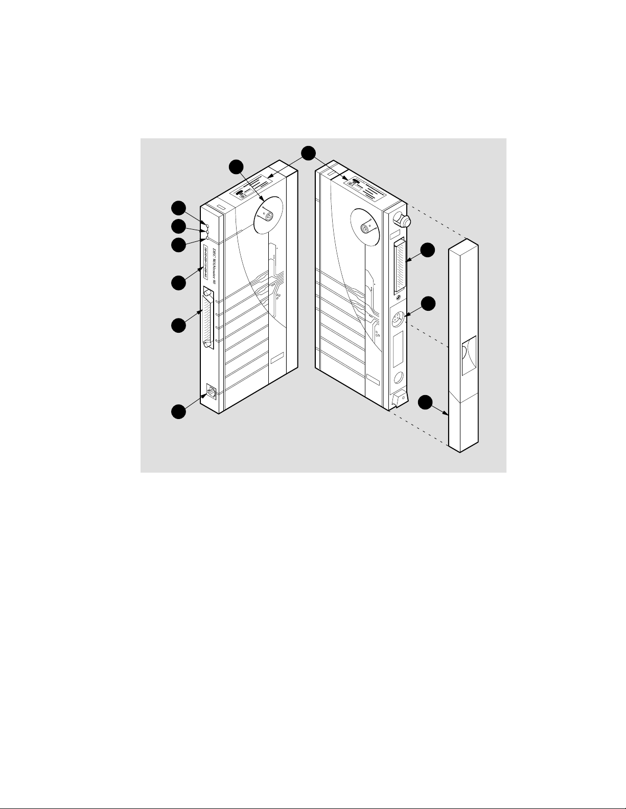
1.5 Controls, Indicators, and Connectors
Figure 1–1 shows the DEC WANrouter 90 and calls out its controls, indicators, and
connectors. The controls, indicators, and connectors are described in Table 1–1.
Figure 1–1: DEC WANrouter 90
11
7
1
2
3
4
5
6
8
9
10
LKG-5965-92I
NOTE
Pins 13 and 16 on the 50
European versions of the DEC WANrouter 90.
ent on
-pin connector are not pres-
1–4 DEC WANrouter 90 Owner’s Manual
Page 31

Table 1–1: Controls, Indicators, and Connectors
Item
1 Power
Indicator
2 System OK
Indicator
3 Network OK
Indicator
4 Ethernet
Address
550-pin D-sub
Connector
6 Console Port
Connector
(MMJ)
7 Network
Connector
(BNC)
8 Backplane
Connector
9 Power
Connector
10 Cover
1 1 PTT Label
Description
Turns on when +5 volts is supplied to the unit.
Turns on when the unit has successfully completed its diagnostics.
Turns on when the unit is connected to a properly terminated
network and software has been successfully downline loaded.
Unique physical address of the unit.
Connects a synchronous or ansynchronous device to the router. The device connects to the port via an adapter cable and an
extension cable. Refer to Appendix A for information about
these cables.
Connects a terminal to the DEC WANrouter 90 for performing
diagnostic procedures and setting parameters.
Connects the unit to the Ethernet LAN. Not used when the unit
is installed in the DEChub 90 Ethernet backplane.
Provides network and power connections to the DEC WANrouter 90 when it is installed in the DEChub 90 Ethernet backplane.
Provides +5 volts from the DEC WANrouter 90 standalone power supply . Not used when the unit is installed in the DEChub 90
Ethernet backplane.
Present on standalone units only. Covers the backplane connector and mounting assembly.
PTT approval label. Contains warning information for installations in the United Kingdom.
1.6 Models
There is only one model of the DEC W ANrouter 90, but this model has several versions depending on whether the unit is intended for:
• Standalone installation or insertion into a DEChub 90 backplane
• Installation in Europe or in a non European country
1–5Introduction
Page 32

The versions of the DEC WANrouter 90 are:
• DEWAR-MA— for insertion into a DEChub 90 backplane installed in any
country outside of Europe.
• DEWAR-ME— for insertion into a DEChub 90 backplane installed in any
European country.
• DEWAR-** — for standalone configurations, where ** refers to the unique
country code that specifies the type of external power supply and cord
shipped with the DEC WANrouter 90.
Refer to Appendix B for information about DEC W ANrouter 90 order codes, and for
information about DEC WANrouter 90 accessories and cables.
1.7 Management Tools
The following tools are available for managing the DEC WANrouter 90:
• Light emitting diodes (LEDs)— Three LEDs provide status information that
help in managing and troubleshooting the router. Refer to Chapters 3 and 4
for information on the DEC WANrouter 90 LEDs.
• Console port—A terminal can be attached to the router’s console port for per-
forming diagnostic functions. Generally, this port is only used by Digital
Field Service personnel. However, in the event of a hardware problem, Digital Field Service may request you to collect status information from the router
by connecting a terminal to this port to display informational and error messages. The informational/error messages are automatically sent to the console
port by the router’s firmware. Chapter 3 discusses how to connect a terminal
to the console port.
• MOP—The software installer uses MOP to down-line load operational soft-
ware to the DEC WANrouter 90 from a load host. Refer to the appropriate
DEC WANrouter 90/150/250 Installation guide for further information.
• Network Control Language (NCL)—NCL can be used manage the router
from a remote location. For information about using NCL to manage the
DEC WANrouter 90, refer to DEC WANrouter Management.
1–6 DEC WANrouter 90 Owner’s Manual
Page 33

• SNMP—SNMP can be used to manage the router using Hubwatch software.
For information about using this tool to manage the DEC WANrouter 90, refer to Hubwatch for DECmcc MSU and Hubwatch for Windows
NOTE
Although the SNMP management manuals describe
how to use both GET s and SETs, the DEC WANrouter
90 only supports GET s.
TM
1.8 Software Requirements
The software requirements for installing and operating the DEC WANrouter 90 depend on the type of load host used for down-line loading the operational software:
.
• For a VMS
TM
load host, the VMS operating system V5.4 and DECnet exten-
sions must be installed on the DEC WANrouter 90 system load host.
• For an ULTRIX
TM
load host, the ULTRIX operating system V4.2 and
DECnet/OSI for ULTRIX must be installed on the DEC WANrouter 90 system load host.
• DEC WANrouter 90 distribution software must be installed on each DEC
WANrouter 90 system load host.
The distribution software includes a router image file that is down-line loaded over
the Ethernet or the serial line to the DEC WANrouter 90. The load host down-line
loads the router image whenever required, and provides the router image to any number of routers. The router image, running on the DEC WANrouter 90, enables the
router to perform its functions.
NOTE
The DEC WANrouter 90 hardware is configured at the
factory for down-line loading over the Ethernet. Appendix C provides instructions for configuring the router for down-line loading over the serial line.
All software must be installed and verified before you can operate the router. For
more information, refer to the appropriate DEC W ANrouter 90/150/250 Installation
guide.
1–7Introduction
Page 34

1.9 Product Specifications
This section describes the physical, electrical and environmental specifications of
the DEC WANrouter 90.
1.9.1 Physical Dimensions
Table 1–2 lists the physical dimensions of the DEC WANrouter 90.
Table 1–2: Physical Dimensions
Dimension
Height 3.18 cm (1.25 in)
Width
Depth
Weight
Value
27.31 cm (10.75 in)
12.70 cm (5.0 in)
.77 kg (1.7 lb)
1.9.2 Electrical Specifications
Table 1–3 lists the electrical characteristics for the DEC WANrouter 90.
Table 1–3: Electrical Specifications
Voltage
+5.0 V 1.2 A 6.0 W
Current (Ampere) Power (Watts)
1–8 DEC WANrouter 90 Owner’s Manual
Page 35

1.9.3 Environmental Requirements
Table 1–4 lists the environmental requirements of the DEC WANrouter 90.
Table 1–4: Environmental Requirements
Parameter
Operating Environment:
Temperature
Maximum rate of change
Relative humidity 10% to 95% (noncondensing)
Wet-bulb temperature
Altitude Sea level to 2.4 km (8000 ft)
Air flow Convectively cooled. A minimum of 10 cm
Nonoperating environment:
Temperature
Relative humidity Up to 95% (noncondensing)
Altitude Up to 4.9 km (16,000 ft)
Value
° C to 50° C (41° F to 122° F)
5
20
° C/hr (36° F/hr)
32
° C (90° F)
(4 in) of space must be provided on both
ends of the unit for adequate air flow.
–40
° C to 66° C (–40° F to 151° F)
1–9Introduction
Page 36

1.9.4 Power Supply Specifications
T able 1–5 lists the electrical specifications of the DEC W ANrouter 90 power supply.
Table 1–5: Power Supply
Parameter
Voltage (Domestic) 104 Vac to 128 Vac (nominal 120 Vac)
Voltage (International) 208 Vac to 256 V ac (nominal 240 Vac)
Current at 120 V .25 A
Current at 240 V .125 A
Frequency 50 Hz to 60 Hz
Power Consumption 16 W
Output voltage 5.1 Vdc
Output current
Value
1.8 A
1.10 Installation Overview
Installing the DEC WANrouter 90 involves the following tasks:
• Preparing for the installation, including:
– Reviewing the site verification checklist
– Unpacking the unit and checking the contents of the shipment
– Verifying site requirements
• Placing or mounting the router
• Connecting to the Ethernet or inserting the router into a DEChub 90 Ethernet
backplane
• Testing the router hardware
• Connecting a device to the 50-pin serial port
• Connecting a terminal to the console port (optional)
• Completing the installation
1–10 DEC WANrouter 90 Owner’s Manual
Page 37

Figure 1–2 lists the steps of the DEC W ANrouter 90 installation and identifies where
in the manual each task is described.
Figure 1–2: DEC WANrouter Installation Overview
1.
Review the site verification checklist.
Unpack the unit and check the contents
2. Refer to Section 2.2.
of the shipment.
Refer to Section 2.1.
3.
4.
5.
Verify site requirements.
Place or mount the router.
Connect to the Ethernet or insert the
router into a DEChub 90 Ethernet
backplane
6.
7.
Connect a terminal to the console port.
8.
(Optional)
9.
Test the router hardware.
Connect a device to the 50-pin serial
port.
Complete the installation.
Refer to Section 2.3.
Refer to Section 3.2.
Refer to Sections 3.2.2 or
3.3, respectively.
Refer to Section 3.4.
Refer to Section 3.5.
Refer to Section 3.6
Refer to Section 3.7 (and also
the
DEC WANrouter
90/150/250 Installation Guide).
LKG-6514-92I
1–11Introduction
Page 38

Preparing for Installation
This chapter describes the contents of the shipment and provides important site verification information to consider before installation.
2.1 Site Verification Checklist
Site verification ensures that the site has been properly prepared to accept the installation with a minimum of system downtime. Use the following checklist to verify all
site preparation tasks have been completed before beginning the DEC WANrouter
90 installation:
2
General
Determine where the router will be installed.
Ensure that the system manager is notified if you intend to shut down the
system during the installation.
2–1
Page 39

Hardware
Ensure that the ThinWire Ethernet LAN is in place and operable.
Ensure that a DEChub 90 Ethernet backplane is installed and operable; or
if this is a standalone installation, ensure that arrangements have been
made to connect the router’s Ethernet port to a suitable Ethernet interface
device (a DEMPR, a DESPR or a ThinWire segment), and that an appropriate ac power source is within 1.6 m (5.5 ft) of the router.
Ensure that the appropriate synchronous or asynchronous device (a modem, personal computer, or host) is ready for connection to the router’s
serial port.
Electrical and Environmental Requirements
Ensure that the electrical and environmental requirements are within the
ranges described in the DEC WANrouter 90 specifications listed in
Chapter 1.
Cabling Requirements
Ensure that the required adapter cable for connecting the synchronous or
asycnhronous device to the DEC WANrouter 90’s 50-pin port has been
obtained. Note that this cable is not included in the shipment. Refer to
Appendix A for information about the type of cables to use. Refer to Appendix B for information about ordering cables.
Ensure that appropriate types and lengths of cable are available for connection to the Ethernet (if this is a standalone installation).
Service
Make sure the (optional) service contracts are in place. Call your Digital
sales representative for information on available hardware and software
services to support the DEC WANrouter 90.
2–2 DEC WANrouter 90 Owner’s Manual
Page 40

2.2 Unpacking and Checking the Contents of Shipment
Unpack the unit and check the shipment for damage or missing parts. Figure 2–1
shows the contents of the shipment for the DEW AR-MA and DEW AR-ME versions
of the the DEC WANrouter 90. For the standalone versions, the shipment also includes a power supply and power supply cord. Refer to Appendix B for a list of the
items shipped with each version.
If any items are damaged or missing, immediately notify the delivery agent and the
Digital sales representative.
NOTE
Save the original packing material should you need to
return the unit to Digital.
Figure 2–1: Hardware Kit Contents (DEWAR
DEC WANrouter 90 Owner’s
Manual
H3199 Loopback
Connector
-MA and DEWAR-ME)
LKG-6065-92I
2–3Preparing for Installation
Page 41

2.3 Verifying Electrical, Environmental, and Cable Requirements
The router can operate as a standalone unit in an office environment or as a module
installed in a DEChub 90 Ethernet backplane. Regardless of where you install the
router, verify that all of the requirements in this section are met before beginning the
installation.
2.3.1 Electrical Requirements
The power at the electrical outlet must match the requirements specified in Table
1–1. Refer to Chapter 1.
2.3.2 Environmental Requirements
Environmental requirements for temperature and humidity must be within the
ranges shown in Table 1–2. Refer to Chapter 1.
2.3.3 Cabling Requirements
The cabling requirements of the router are discussed in this section. For additional
information on cabling and configuring of local area networks, and using DECconnect system products, refer to the DECconnect System Planning and Configuration
Guide (see Appendix C for information on how to order this document).
2.3.3.1 Maximum Cable Lengths
T able 2–1 shows the maximum cable lengths for a number of data rates using DEC
WANrouter 90 supported line interface standards.
2–4 DEC WANrouter 90 Owner’s Manual
Page 42

Table 2–1: Maximum Cable Lengths — Router to Devices
Line Protocol Data Rate (b/s) Cable Length
EIA-232-D/V.24
RS-423-A
RS-422-A
V.35
Up to 20 K
Below 4.8 K
20 K
48 K
64 K
Up to 64 K
48 K
15 m (50 ft)
1200 m (4000 ft)
150 m (500 ft)
58 m (190 ft)
25 m (80 ft)
1200 m (3900 ft)
60 m (200 ft)
Table 2–1 assumes the following:
• The V.24 cable capacitance is 50 pF/ft.
• The RS-423-A cable capacitance is 15 pF/ft.
• The RS-422-A cable is 100 ohm terminated with a capacitance of 15 pF/ft.
The maximum cable length for V.35 is a recommended figure only.
2.3.3.2 ThinWire Ethernet Connection
If you are installing the DEC WANrouter 90 in a standalone configuration, ensure
that the following requirements are met:
• The maximum ThinWire cable segment length must not exceed 185 m
(606 ft).
• There must be a 50-ohm terminator at each end of the cable segment unless
the cable ends in a DEMPR or DESPR (both these devices have inbuilt
50-ohm terminators).
• There must be only one ground per cable segment.
• There must be at least 0.5 m (19 in) between T-connectors.
• The maximum number of stations, between terminators, must not exceed 30.
2–5Preparing for Installation
Page 43

• ThinWire cable segments must not be configured in a loop.
• ThinWire cable segments must not have any branch segments.
2.4 Software Considerations
The router software and software installation instructions are shipped separately
from the DEC W ANrouter 90 hardware. Before starting the installation described in
the following chapter, check with the system manager to verify that the router software is ready for down-line loading over the Ethernet or serial line.
It is recommended that you install the DEC WANrouter 90 after the software is installed on the load host. This will allow you to verify the complete system installation. If you install the hardware before the software is installed, the Network OK
LED will indicate an error when power is applied to the unit, as described in Section
3.4. If you install the hardware before the software is installed, the software installer
is responsible for verifying the complete system installation.
2–6 DEC WANrouter 90 Owner’s Manual
Page 44

Installing the DEC WANrouter 90
This chapter describes how to install the DEC WANrouter 90. There are two types of
installations for the DEC WANrouter 90:
• As a standalone unit placed on a table or desktop, or mounted to a wall
• Inserted into a DEChub 90 Ethernet backplane
3.1 Overview
The DEC WANrouter 90 can be placed on a table or desktop, mounted to a wall, or
inserted into a DEChub 90 Ethernet Backplane. T o install the DEC W ANrouter 90 as
a standalone unit, refer to Section 3.2. To install the DEC WANrouter 90 in a
DEChub 90 Ethernet backplane, refer to Section 3.3. Once the unit is installed, refer
to Section 3.5 to connect a device to the router’s 50-pin serial port.
3
CAUTION
Before installing the DEC WANrouter 90 in the United
Kingdom (U.K.), you must refer to Appendix D.
3.2 Installing in a Standalone Configuration
Figure 3–1 illustrates the DEC WANrouter 90 installed in a standalone configuration using a domestic power supply . Figure 3–2 illustrates the same type of configuration, except using an international power supply. Refer to these figures when
performing the procedures described in this section.
3–1
Page 45

Figure 3–1: DEC WANrouter 90 Standalone Installation
with Domestic Power Supply
Domestic
Power Supply
50 ohm
Terminator
T-Connector
LKG-6626-92I
3–2 DEC WANrouter 90 Owner’s Manual
Page 46

Figure 3–2: DEC WANrouter 90 Standalone Installation
with International Power Supply
International
Power Supply
50 ohm
Terminator
T-Connector
LKG-6625-92I
3–3Installing the DEC WANrouter 90
Page 47

3.2.1 Placing or Mounting the DEC WANrouter 90
Place or mount the DEC WANrouter 90. For desktop installation, stand the unit on
end or lay the unit horizontally.
For wall mounting, remove the back cover of the unit and mount the unit on the wall,
as described in the following subsections.
3.2.1.1 Removing the Back Cover (for Wall Mounting)
To remove the back cover of the DEC WANrouter 90, refer to Figure 3–3 and perform the following steps:
1. Insert a small screwdriver into the top mounting hole in the cover.
2. Lift up on the latch.
3. While lifting up on the latch, pull the top of the cover away from the unit and
down.
3.2.1.2 Wall Mounting
Once you have removed the back cover, use the mounting holes on the cover as a
template to locate the mounting screws. The screws are not supplied with the router.
After marking for the mounting screws, mount the back cover to the wall and then
snap the unit into the back cover.
3–4 DEC WANrouter 90 Owner’s Manual
Page 48

Figure 3–3: Removing the Back Cover of the DEC WANrouter 90
3.2.2 Connecting the Router to the Ethernet
Once the unit is placed or mounted, perform the following steps to connect the router
to the ThinWire Ethernet local area network:
1. Attach the Ethernet T-connector to the BNC connector on the DEC
WANrouter 90, as illustrated in Figure 3–4.
LKG–6722–92I
3–5Installing the DEC WANrouter 90
Page 49

Figure 3–4: Connecting to the ThinWire Ethernet LAN
Inserting ThinWire
T-Connector
Locking ThinWire
T-Connector
50-ohm
Terminator
LKG-5970-92
2. Turn the barrel of the connector clockwise to lock (see Figure 3–4).
3–6 DEC WANrouter 90 Owner’s Manual
Page 50

NOTE
Figure 3–4 shows the T-connector terminated using a
50-ohm terminator. The 50-ohm terminator is replaced
by a cable if the router is not at the end of a cable segment. The cable segment must be terminated by 50-ohm
terminators at both ends unless a DEMPR or a DESPR is
used. Where a cable segment is terminated in a DEMPR
or a DESPR at one end only, the opposite end needs to
have a 50-ohm terminator.
3.2.3 Completing the Standalone Router Installation
To complete the standalone router installation, perform the following steps:
1. Connect the H3199 loopback connector to the router’s 50-pin male D-connector.
2. Plug the external power supply connector into the DEC WANrouter 90’s
power connector.
3. Attach the power cord to the power supply (if you are using an international
power supply).
4. Plug the power supply or power supply cord into a working ac outlet.
5. With the power applied to the DEC WANrouter 90, the unit’s Power LED is
lit and the router starts its self-test. The self-test takes approximately one minute to complete. Refer to Section 3.4 for information about running the self
test.
3.3 Installing in a DEChub 90 Ethernet Backplane
T o install the DEC WANrouter 90 in a DEChub 90 Ethernet backplane, perform the
procedures described in this section.
-
3–7Installing the DEC WANrouter 90
Page 51

3.3.1 Removing the Back Cover (if necessary)
If there is a cover on the back of the router, you must remove it before inserting the
router into the backplane. Perform the following steps to remove the back cover:
1. Insert a small screwdriver into the top mounting hole in the cover (see
Figure 3–3).
2. Lift up on the latch.
3. While lifting up on the latch, pull the top of the cover away from the unit and
down.
3.3.2 Inserting the DEC WANrouter 90 into the DEChub 90 Ethernet Backplane
Perform the following steps to insert the router in the DEChub 90:
1. Place the lower mounting tab, located on the back of the DEC WANrouter 90,
into a mounting slot on the backplane, as shown in Figure 3–5. Use any slot
except slot 8.
NOTE
The DEC W ANrouter 90 can be installed in the DEChub
90 Ethernet backplane while the backplane is poweredup and connected to the network. Similarly, once the
router is mounted you can replace the router (if necessary) with another router (‘hot swap’) without having to
power down the backplane.
2. Connect the H3199 loopback connector to the 50-pin male D-connector on
the router.
3. Rock the unit into place. An audible click is heard when the unit is securely
latched in place.
With the power applied to the backplane, the router’s Power LED is lit and the unit
starts its self-test. The self-test takes approximately one minute to complete. Refer
to Section 3.4 for information about running the self-test.
3–8 DEC WANrouter 90 Owner’s Manual
Page 52

Figure 3–5: DEC WANrouter 90 Backplane Installation
3.4 Testing the Router Hardware
Plugging in the router power cord, or inserting the router into a powered-up DEChub
90 backplane, applies power directly to the router and causes the router to automatically begin its self-test. The self-test consists of diagnostic routines that test and
verify the operation of the unit. Pass/fail test results are indicated by the router’s
LEDs.
LKG-5966-92I
3–9Installing the DEC WANrouter 90
Page 53

The following sequence of events occur at power up:
1. As soon as power is applied to the unit, the green Power LED is lit.
2. Core tests are run to verify that the router’s data and address registers function correctly.
3. Next, the PROM and DRAM are verified. Following these tests, the remaining logic is tested.
4. The self-test takes approximately one minute. The results of the self-test are
displayed by the unit’s LEDs:
a. If only the Power LED is lit, it indicates that the self-test failed.
b. If the Power LED is lit, and the System OK LED is blinking, it indicates
that the self-test failed, but the core is operational.
c. If both the Power and System OK LEDs are lit, it indicates that the unit
passed its self-test.
5. Upon successful completion of the self-test, the router attempts to down-line
load the DEC WANrouter 90 software image over the Ethernet LAN, from a
suitably configured load host. During this process, both the Power LED and
System OK LED remain lit.
6. If the operational software is successfully loaded, the Network LED is lit and
remains on, along with the Power and System OK LEDs.
7. If the software is not available (for example, if it has not been installed on the
load host, or the load host is not functioning), the Network LED will blink
momentarily and then extinguish.
Table 3–1 summarizes the states of the DEC WANrouter 90 LEDs.
3–10 DEC WANrouter 90 Owner’s Manual
Page 54

Table 3–1: States of the DEC WANrouter 90 LEDs
Power LED
Off Off Off No power.
On Off
On Blinking
On On
On On
On
System OK Network LED Meaning
-test failed.
-test failed, but
core is operational.
software image
successfully loaded.
-test passed.
Router is attempting
to find the load host.
could not find the
software image.
On
Off Self
Off Self
On Self-test passed and
Off Self
Blinking Self-test passed but
3.4.1 Evaluating Test Results
Upon completion of the self-test, examine the state of the DEC W ANrouter 90 LEDs
to evaluate the test results.
3.4.1.1 Self-Test Successful and Network LED Remains Lit
If the DEC W ANrouter 90 successfully completes its self-test, and the Network LED
remains lit (indicating the software has been successfully loaded), perform the following steps:
1. Remove the H3199 loopback connector from the 50-pin port connector.
2. Proceed to connect a device to the serial port, as described in Section 3.5.
3.4.1.2 Self-Test Fails
If the DEC W ANrouter 90 fails its self-test (for example, both the Power and System
OK LEDs do not remain lit), refer to Chapter 4.
3–11Installing the DEC WANrouter 90
Page 55

3.4.1.3 Self-Test Successful But Network LED Not Lit
If the Network LED is not lit or blinks (indicating that the DEC W ANrouter 90 software has not been down-line loaded to the router), check with the system manager
to:
• Determine if the DEC WANrouter 90 software has been installed on the load
host.
• Determine whether the software will be down-line loaded over the Ethernet
or over the serial line.
If the router software is not installed on the load host, notify the system manager that
the software needs to be installed in order to complete the router installation.
If the system manager informs you that the router software has already been installed
on the load host, and must be down-line loaded over the serial line, perform the following steps:
1. Remove the H3199 loopback connector from the 50-pin port connector.
2. Connect a device to the serial port, as described in Section 3.5.
3. Connect a terminal to router’s console port connector, as described in
Section 3.6.
4. Configure the serial port for down-line loading, as described in Appendix C.
5. After completing these steps, examine the state of the Network LED. At this
point, the Network LED should remain lit. If it is not lit, nofity the system
manager.
3.5 Connecting a Device to the 50-Pin Device Port
T o connect a device to the router’s serial port, you need an adapter cable (and, if necessary , an extension cable). Appendix A provides detailed information about which
adapter cable and extension cable to use, depending on the type of device you are
connecting.
3–12 DEC WANrouter 90 Owner’s Manual
Page 56

NOTE
Since the DEC WANrouter 90 is typically used to connect an Ethernet LAN to a wide area network through a
modem, this section uses the example of connecting a
modem to the 50-pin port.
To connect a device to the router’s serial port, perform the following steps:
1. Connect the 50-pin female D-connector of the adapter cable to 50-pin male
D-connector on the router (see Figure 3–6).
Figure 3–6: Connecting to the 50-Pin D-Connector
1. Insert the 50-Pin D-connector.
2. Tighten the screws.
LKG-5968-92I
3–13Installing the DEC WANrouter 90
Page 57

2. If necessary, connect the adapter cable to an extension cable (see Figure 3–7).
Figure 3–7: Connecting an Adapter Cable to an Extension Cable
Adapter Cable
Extension Cable
LKG-5972-92I
3. Connect the adapter cable or extension cable to the device. Figure 3–8 illustrates how the adapter or extension cable is connected to a modem.
3–14 DEC WANrouter 90 Owner’s Manual
Page 58

Figure 3–8: Connecting to the Modem
1. Attach cable.
2. Tighten screws.
CAUTION
For V.24 installations, a V24/RS-232-C adapter
(12-27591-01) must be fitted between the adapter cable and
the extension cable, or between the adapter cable and the modem (refer to Figure 3–9), if the modem/eliminator has any
of the following:
• A signal with a DCE source on pin 18
• Signal quality implemented on pin 21
LKG-5973-92I
3–15Installing the DEC WANrouter 90
Page 59

• Data Signal Rate Selector (DCE) on pin 23
Failure to comply with this could result in damage to the in-
terface module and modem or modem eliminator. If you are
not sure what signals the modem or modem eliminator provides, contact Digital Field Service.
Figure 3–9: Connecting an Adapter Cable, a V24/RS-232-C Adapter, and an
Extension Cable
V24/RS-232-C Adapter
(12-27591-01)
Adapter
Extension Cable
Note: If the extension
cable is not used, the
adapter connects directly to the modem
or modem eliminator.
3.6 Connecting a Terminal to the Console Port Connector
To connect a terminal to the console port connector, do the following:
1. Insert the cable’s modified modular plug (MMP) into the router’s modified
modular jack (MMJ) connector, as shown in Figure 3–10.
LKG-5974-92I
3–16 DEC WANrouter 90 Owner’s Manual
Page 60

Figure 3–10: Connecting to the Console Port Connector
MMJ
Connector
MMP
LKG-5969-92I
2. Insert the cable’s modified modular plug (MMP) into the modified modular
jack (MMJ) connector on the terminal, as shown in Figure 3–11. If the terminal has a 25-pin D-connector, use an H8571-A adapter (see Figure 3–12).
3–17Installing the DEC WANrouter 90
Page 61

Figure 3–11: Connecting to the Terminal
MMJ Connector
MMP
LKG-5975-92I
3–18 DEC WANrouter 90 Owner’s Manual
Page 62

Figure 3–12: Connecting to 25-Pin D-Connector Terminal
1. Insert the H8571-A adapter.
2. Tighten the screws.
3. Insert the MMP.
LKG-5976-92I
3. Power up the terminal.
4. Configure the terminal to operate with a speed of 9600 bits/s and with a character size of 8 bits (no parity). Refer to the specific terminal user’s guide if
you need help setting the terminal parameters.
3–19Installing the DEC WANrouter 90
Page 63

3.7 Completing the Router System Installation
After you install and test the DEC W ANrouter 90 hardware, inform the system manager that the router installation is complete.
If you have installed the router hardware without the router software installed on the
load host, it is the system manager’s responsibility to verify the total system installation after installing the software. Instructions for verifying the total system installation are provided in the DEC WANrouter 90/150/250 Installation guide.
3–20 DEC WANrouter 90 Owner’s Manual
Page 64

Troubleshooting
This chapter describes how to troubleshoot the DEC WANrouter 90 hardware.
4.1 General Information
The troubleshooting information in this chapter helps you identify and correct problems you may encounter during the installation of the DEC W ANrouter 90 hardware.
These troubleshooting procedures are for diagnosing and correcting hardwarerelated problems only. Notify the network manager if the troubleshooting procedures indicate the problem is software related or if the procedures do not correct the
problem.
4
4.2 Troubleshooting Guidelines
Refer to the following guidelines when troubleshooting the DEC WANrouter 90
hardware:
• Always check for loose cable connections before commencing extensive
troubleshooting.
• Consider possible environmental problems, such as power fluctuations or
high ambient temperatures.
• When corrective action is indicated (such as checking for loose cables, and so
on) power down the system before performing those actions.
4–1
Page 65

• If the DEC WANrouter 90 has been functioning for a while without any prob-
lems, but now indicates a fault, it is possible that the fault is in a related device, for example, the DEChub 90 Ethernet backplane, the Ethernet segment,
the device connected to the router’s serial port, or the device cables.
• When the fault is isolated to a malfunction of a connected device or cable,
replace the device or cable or refer to their associated documents for troubleshooting information.
• When the fault is isolated to the DEC WANrouter 90, contact your Digital
Sales Representative to make arrangements for a replacement unit.
4.3 Troubleshooting Tools
The self-test diagnostic program and the DEC W ANrouter 90 LEDs are the primary
diagnostic tools used for troubleshooting the router hardware. Pass or fail test results are indicated by the combined states of the router’s LEDs. Table 4–1 lists the
various states of the LEDs.
Also, you can connect a terminal to the console port connector (as described in Chapter 3) and monitor any error messages that are sent to the console port by the router
firmware.
4–2 DEC WANrouter 90 Owner’s Manual
Page 66

Table 4–1: States of the DEC WANrouter 90 LEDs
Power LED
Off Off Off No power.
On Off Off Self-test failed.
On Blinking Off Self-test failed, but
On On On Self-test passed and
On On Off Self-test passed.
On
System OK Network LED Meaning
core is operational.
software image
successfully loaded.
Router is attempting
to find the load host.
On Blinking Self-test passed but
could not find the
software image.
4.4 Troubleshooting Procedure
To troubleshoot the DEC WANrouter 90 hardware, refer to Table 4–1 and to the
diagnostic flow chart in Figure 4–1.
4–3Troubleshooting
Page 67

Figure 4–1: Diagnostic Flowchart
Start
Power on and
self-test
Is this a
standalone
installation
1. Check the power con nection to the router.
2. Ensure that the power
cord is properly con nected to the router,
power supply , and
power outlet.
3. Verify that the AC
power outlet is working.
Power LED on
?
Yes
No
?
Yes
1. Verify that the
DEChub 90 Ethernet
backplane is receiving
power. Refer to the
No
DEChub 90 Ethernet
Backplane Owner’s
Manual
on troubleshooting
the backplane.
2. Ensure that the router
is firmly seated in the
backplane.
for instructions
No
Replace the router
Power LED on
Replace the router.
?
Yes
1
Legend:
= Off-page reference tag.
LKG-6489-92I
4–4 DEC WANrouter 90 Owner’s Manual
Page 68

Figure 4–1 (Cont.): Diagnostic Flowchart
1
System
OK LED
?
Yes
Self-test successful
A
Network
LED is lit
?
Yes
Router has
successfully loaded
the software image
and is fully functional.
Legend:
No No
System
OK LED
blinking
?
Yes
Router core passed
self-test; however,
the router is not
operational.
Replace the router.
No No
Network
LED blinks and
then extinquishes
?
Yes
Indicates the router has failed to
locate the DEC WANrouter 90
software image.
Ensure that the system manager
has installed the software on a
suitable load host, and that the
load host is powered on and
connected to the network.
If the software is being loaded
over the serial line, ensure that
the serial port is configured for
down-line loading.
Self-test failed.
Replace the router.
Router is attempting to
load the DEC
WANrouter 90
software image from
the load host.
A
= Off-page reference tag. = On-page reference tag.
LKG-6490-92I
4–5Troubleshooting
Page 69

Connector and Cable Pin Descriptions
This appendix describes the pins of the DEC WANrouter 90 hardware connectors
and the cables used to interface to the DEC WANrouter 90 hardware. Wiring diagrams of the individual cables are included to help you in troubleshooting and cable
building.
A.1 Connector Pin Descriptions
This section describes the pins for the following DEC WANrouter 90 connectors:
• ThinWire Ethernet connector
• Device port connector
• Console port connector
A.1.1 Ethernet Transceiver Interface
A
The DEC WANrouter 90 unit has a ThinWire Ethernet connector that is used when
the unit is installed in a standalone configuration. The ThinWire Ethernet connector
is a 50-ohm, RG58 type, BNC connector with one pin and a shield.
A–1
Page 70

A.1.2 Device Port Connector
The 50-pin D-connector is used to connect a synchronous or asynchronous device
(modem, personal computer, and so forth) to the router . The device must support one
of the following standards:
• EIA-232-D/V.24/V.28
• RS-449,RS-423-A/V.10
• RS-449,RS-422-A/V.11
• V.35
• V.36
• X.21 Leased Circuit
• BT Kilostream Service
Figure A–1 shows how the pins are numbered and Table A–1 describes the signals
on each pin.
Figure A–1: Pin Numbers for 50-Pin D-Connector
Pin 1
Pin 18 Pin 33
Pin 34
NOTE
A separate adapter cable is required for each standard.
Section A.2.1 provides information on the correct
adapter cables to use.
A–2 DEC WANrouter 90 Owner’s Manual
Pin 17
Pin 50
LKG-5977-92I
Page 71

Table A–1 : Pin Descriptions for 50-Pin D-Connector
Signal Signal
Pin Description Name EIA-232-D V.24 RS-423 RS-422 V.35 X.21 BT
Code Gnd
1
Code 0 *
2
Code 1 *
3
Code 2 *
4
Code 3 *
5
Transmitted data A
6
Transmitted data B
7
Transmitted data
8
Request to send A
9
Request to send B
10
Received data A
11
Received data B
12
Local Loop
13
Data signal rate
14
selector (DCE)
Test indicator
15
Remote loopback
16
Ring indicator
17
Receiver signal
18
element timing (DCE) A
Receiver signal
19
element timing (DCE) B
Transmit signal
20
element timing
(DCE) A
Transmit signal
21
element timing
(DCE) B
Transmit signal
22
element timing
(DTE)
V35 Transmit signal
23
element timing
(DCE) A
V35 Transmit signal
24
element timing
(DCE) B
V35 Transmit signal
25
element timing
(DTE) A
V35 Transmit signal
26
element timing
(DTE) B
* Code <0:3> identifies the adapter cable that is attached to the 50-pin connector.
TXD A
TXD B
TXD
RTS A
RTS B
RXD A
RXD B
LOC LPBK
SMI
TEST IND
REM LPBK
RI
RXCLK A
RXCLK B
TXCLK A
TXCLK B
CLK
V35 TXCLK A
V35 TXCLK B
V35 CLK A
V35 CLK B
BA
BB
earth
LL
CI
TM
RL
CE
DD
earth
DB
earth
DA
103
104
earth
141
112
142
140
125
115
earth
114
earth
113
SD
RD
RD
LL
TM
RL
IC
RT
RT
ST
ST
TT
SD
SD
RS
RS
RD
RD
LL
TM
RL
IC
RT
RT
ST
ST
114
114
113
113
T
T
C
C
R
R
B
B
S
S
NOTE
T
T
R
R
S
S
Pins 13 and 16 are not present on the European versions
of the DEC WANrouter 90.
A–3Connector and Cable Pin Descriptions
Page 72

Table A-1 : Pin Descriptions for 50-Pin D-Connector (Cont.)
Signal Signal
Pin Description Name EIA-232-D V.24 RS-423 RS-422 V.35 X.21 BT
V35 RXD A
27
V35 RXD B
28
V35 TXD A
29
V35 TXD B
30
V35 Receiver signal
31
element timing (DCE)
A V35 Receiver signal
32
element timing (DCE) B
Data terminal ready
33
Data set ready A
34
Data set ready B
35
Request to send
36
Data channel
37
received line signal detector A
Data channel
38
received line signal detector B
Clear to send send A
39
Clear to send B
40
DCE ground
41
Test transmit data
42
Test RTS
43
DTE ground
44
Data terminal
45
ready A
Data terminal
46
ready B
Terminal Timing A
47
Terminal Timing B
48
Test transmit clock
49
Data signal rate
50
selector
** These three pins are used for testing.
V35 RXD A
V35 RXD B
V35 TXD A
V35 TXDB
V35 RXCLK A
V35 RXCLK B
DTR
DSR A
DSR B
RTS
DCD A
DCD B
CTS A
CTS B
DCE GND
TEST TXD
TEST RTS
DTE GND
DTR A
DTR B
CLOCK A
CLOCK B
TEST TXCLK
DSRS
CD
CC
earth
CA
CF
earth
CB
earth
earth
**
**
AB
**
CH
108/2
107
earth
105
109
earth
106
earth
earth
**
**
102
**
111
TR
DM
DM
RS
RR
RR
CS
CS
RC
SC
SR
DM
DM
RR
RR
CS
CS
RC
SC
TR
TR
TT
TT
SR
104
104
103
103
115
115
107
earth
105
109
earth
106
earth
earth
102
I
I
Ga
A.1.3 Console Port Connector
The console port connector on the DEC WANrouter 90 is a modified modular jack
(MMJ). The MMJ supports DEC 423 Data Leads Only connections.
Figure A–2 shows how the pins are numbered on an MMJ connector and Table A–2
lists the signals on the pins.
A–4 DEC WANrouter 90 Owner’s Manual
Page 73

Figure A–2: Pin Numbers for the Console Port Connector
Pin 1 6
LKG-5978-92I
Table A–2 : Pin Descriptions for Console Port Connector
Pin Number Signal Name
1
2
3
4
5
6
Tied to VCC via 150-ohm resistor
Txdata
Txcommon
(N.C.)
Rxdata
Tied to GND via 3K-ohm resistor
A.2 Cable Structure
This section describes the cable structures that are compatible with the device port
and console port on the DEC WANrouter 90. Wiring diagrams of individual cables
are provided for use in troubleshooting and cable building.
NOTE
For the European versions of the DEC WANrouter 90,
ignore the connections for pins 13 and 16 shown in the
cable wiring diagrams in this section. These pins are not
present on the European versions of the DEC
WANrouter 90.
A–5Connector and Cable Pin Descriptions
Page 74

A.2.1 Device Cables and Loopback Connectors for the Serial Communication
50-Pin D-Connector
Y ou use an adapter cable and extension cable (see Section A.2.2 for information on
extension cables) to connect a device to the 50-pin D-connector. Choose an adapter
cable, to match the standard of the device you wish to connect, from the following
list:
• BC19B-02 — Connects DEC WANrouter 90 to RS-422-A devices
• BC19E-02 — Connects DEC WANrouter 90 to RS-423-A devices
• BC19F-02 — Connects DEC WANrouter 90 to V.35 devices
• BC23V-02 — Connects DEC WANrouter 90 to V.24/RS-232 devices
• BC19D-02 — Connects DEC WANrouter 90 to V.24/RS-232 devices
• BC19V-02 — Connects the standalone version of the DEC WANrouter 90 to
V.24/RS-232 devices
• BC22x–02 — Connects DEC WANrouter 90 to BT Kilostream Service (U.K.)
• BC19C-02 — Connects DEC WANrouter 90 to X.21 leased lines
CAUTION
The V.24 to RS-232-C adapter must be fitted between
the adapter cable (BC23V-02, BC19D-02, or
BC19V-02) and the extension cable if the modem/eliminator has:
• A signal with a DCE source on pin 18
• Signal quality implemented on pin 21
• Data signal rate selector (DCE) on pin 21
Failure to comply with this could result in damage to the
interface module and modem or eliminator. If you are
not sure what signals the modem or eliminator provides,
contact Digital Field Service.
A–6 DEC WANrouter 90 Owner’s Manual
Page 75

Use any of the following loopback connectors from the following list, that match
your adapter cable combination:
• H3199 — Universal 50-pin
• H3198 — Synchronous line loopback (RS-423-A and RS-422-A)
• H3250 — Synchronous line loopback (V.35)
• H3266 — Synchronous line loopback (EIA-232-D)
Sections A.2.1.1 through A.2.1.9 contain more information on these adapters and
connectors.
A.2.1.1 BC19B-02 Synchronous Line Adapter Cable
Use the BC19B-02 synchronous line adapter cable to connect the DEC WANrouter
90 50-pin D-connector to RS-422-A devices. The BC19B-02 is 28-wire cable with a
50-pin, female, D-connector on one end and a 37-pin, male, D-connector on the other
end. Figure A–3 shows the wiring diagram.
A–7Connector and Cable Pin Descriptions
Page 76

Figure A–3: Wiring Diagram for BC19B-02 Synchronous Line Adapter Cable
50-Pin
D-Connector
TXDA
TXDB
RTS A
RTS B
RXD A
RXD B
LOC LBK
SMI
TEST IND
REM LPBK
RI
RXCLK A
RXCLK B
TXCLK A
TXCLK B
DSR A
DSR B
DCD A
DCD B
CTS A
CTS B
DCE GND
DTE GND
DTR A
DTR B
CLK A
CLK B
DSRS
1
2
37-Pin
D-Connector
3
4
6
7
9
10
11
12
13
14 2
15
16
17
18
19
20
21
34
35
37
38
39
40
41
44
45
46
47
48
50
4
22
7
25
6
24
10
18
14
15
8
26
5
23
11
29
13
31
9
27
20
19
12
30
17
35
16
37
TXDA
TXDB
RTS A
RTS B
RXD A
RXD B
LOC LBK
SMI
TEST IND
REM LPBK
RI
RXCLK A
RXCLK B
TXCLK A
TXCLK B
DSR A
DSR B
DCD A
DCD B
CTS A
CTS B
DCE GND
DTE GND
DTR A
DTR B
CLK A
CLK B
= 120-ohm .5w resistors
LKG-5979-92I
A–8 DEC WANrouter 90 Owner’s Manual
Page 77

A.2.1.2 BC19E-02 Synchronous Line Adapter Cable
Use the BC19E-02 synchronous line adapter cable to connect the DEC WANrouter
90, 50-pin, D-connector to RS-423-A devices. The BC19E-02 is 24-wire cable with
a 50-pin, female, D-connector on one end and a 37-pin, male, D-connector on the
other end. Figure A–4 shows the wiring diagram.
Figure A–4: Wiring Diagram for BC19E-02 Synchronous Line Adapter Cable
50-Pin D-Connector
1
TXD
RXD A
RXD B
LOC LBK
SMI
TEST IND
REM LPBK
RI
RXCLK A
RXCLK B
TXCLK A
TXCLK B
CLK
DTR
DSR A
DSR B
RTS
DCD A
DCD B
CTS A
CTS B
DCE GND
DTE GND
DSRS
2
3
4
8
11
12
13
14
15
16
17 15
18
19
20
21
22
33
34
35
36
37
38
39
40
41
44
50
37-Pin D-Connector
4
TXD
6
RXD A
24
RXD B
10
LOC LBK
2
SMI
18
TEST IND
14
REM LPBK
RI
RXCLK A
8
RXCLK B
26
TXCLK A
5
TXCLK B
23
CLK
17
DTR
12
DSR A
11
DSR B
29
RTS
7
DCD A
23
DCD B
32
CTS A
9
CTS B
27
DCE GND
20
DTE GND
19
DSRS
16
22
25
30
35
37
LKG-5980-92I
A–9Connector and Cable Pin Descriptions
Page 78

A.2.1.3 BC19F-02 Synchronous Line Adapter Cable
Use the BC19F-02 synchronous line adapter cable to connect the DEC WANrouter
90, 50-pin, D-connector to V.35 devices. The BC19F-02 is 16-wire cable with a
50-pin, female, D-connector on one end and a 34-pin, male, square connector on the
other end. Figure A–5 shows the wiring diagram.
Figure A–5: Wiring Diagram for BC19F-02 Synchronous Line Adapter Cable
50-Pin
D-Connector
RI
V35 TXCLK A
V35 TXCLK B
V35 CLK A
V35 CLK B
V35 RXD A
V35 RXD B
V35 TXD A
V35 TXD B
V35 RXCLK A
V35 RXCLK B
DTR
DSR A
DSR B
RTS
DCD A
DCD B
CTS A
CTS B
DCE GND
DTE GND
1
2
34-Pin Square
Connector
3
4
17
23
24
25
26
W
27
28
29 P
30
31
32
33
34
35
36
37
38
39
40
41
44
J
RI
Y
V35 TXCLK A
a
V35 TXCLK B
U
V35 CLK A
V35 CLK B
R
V35 RXD A
T
V35 RXD B
V35 TXD A
V35 TXD B
S
V35 RXCLK A
V
X
V35 RXCLK B
H
DTR
DSR A
E
RTS
C
F
DCD A
CTS A
D
DTE GND
A
LKG-5981-92I
A–10 DEC WANrouter 90 Owner’s Manual
Page 79

A.2.1.4 BC23V-02, BC19V-02 and BC19D-02 Synchronous Line Adapter Cables
Use the BC23V-02, BC19V-02, or BC19D-02 synchronous line adapter cable to
connect the DEC W ANrouter 90, 50-pin, D-connector to V.24 devices. These cables
are 16-wire cables with a 50-pin, female, D-connector on one end and a 25-pin, male,
D-connector on the other end. Figure A–6 shows the wiring diagram.
NOTE
The BC19V-02 adapter cable can only be used in a
standalone router configuration.
Figure A–6: Wiring Diagram for BC23V-02, BC19V/D-02 Cables
50-Pin D-Connector
1
TXD
RXD A
RXD B
LOC LBK
SMI
TEST IND
REM LPBK
RI
RXCLK A
RXCLK B
TXCLK A
TXCLK B
CLK
DTR
DSR A
DSR B
RTS
DCD A
DCD B
CTS A
CTS B
DCE GND
DTE GND
DSRS
2
3
4
8
11
12
13
14
15
16
17 22
18
19
20
21
22
33
34
35
36
37
38
39
40
41
44
50
25-Pin D-Connector
2
TXD
3
RXD
18
LOC LBK
12
SMI
25
TEST IND
21
REM LPBK
RI
RXCLK
17
TXCLK
15
CLK
24
DTR
20
DSR
6
RTS
4
DCD
8
CTS
5
GND
7
DSRS
23
LKG-5982-92I
A–11Connector and Cable Pin Descriptions
Page 80

A.2.1.5 BC22X-02 BT Kilostream Adapter Cable (U.K. Only)
Use the BC22X-02 BT Kilostream adapter cable to connect the DEC W ANrouter 90,
50-pin, D-connector to British Telecom’s Kilostream service (through the
BC22Z-xx extension cable and the 64k bit/s, X.21 interface). The BC22X-02 is
7-wire cable with a 50-pin, female, D-connector on one end and a 15-pin, male,
D-connector on the other end. Figure A–7 shows the wiring diagram.
Figure A–7: Wiring Diagram for BC22X-02 BT Kilostream Adapter Cable
50-Pin D-Connector
1
15-Pin D-Connector
120-ohm
.5w
resistors
2
9
4
11
6
13
8
TXDA
TXDB
RXD A
RXD B
TXCLK A
TXCLK B
DTE GND
TXD A
TXD B
RTS A
RTS B
RXD A
RXD B
LOCL LPBK
TEST IND
RI
RXCLK A
RXCLK B
TXCLK A
TXCLK B
DSR A
DSR B
DCD A
DCD B
CTS A
CTS B
DTE GND
DTR A
DTR B
DSRS
2
3
4
6
7
9
10
11
12
13
15
17
18
19
20
21
34
35
37
38
39
40
44
45
46
50
LKG-5983-92I
A–12 DEC WANrouter 90 Owner’s Manual
Page 81

A.2.1.6 BC19C-02 Synchronous Line Adapter Cable
Use the BC19C-02 adapter cable to connect the DEC W ANrouter 90, 50-pin, D-connector to X.21 leased lines. The BC19C-02 is 7-wire cable with a 50-pin, female,
D-connector on one end and a 15-pin, male, D-connector on the other end.
Figure A–8 shows the wiring diagram.
Figure A–8: Wiring Diagram for BC19C-02 Synchronous Line Adapter Cable
50-Pin D-Connector
1
2
T
T
C
C
R
R
B
B
S
S
I
I
Ga
3
4
6
7
9
10
11
12
13
15
17
18
19
20
21
34
35
37
38
39
40
44
45
46
50
15-Pin D-Connector
120-ohm
.5w
resistors
TX DATA A
2
TX DATA B
9
3
CONTROL A
CONTROL B
10
RX DA TA A
4
RX DA TA B
11
7
BYTE TIMING A
14
BYTE TIMING B
SIGNAL TIMING A
6
SIGNAL TIMING B
13
5
INDICATION A
INDICATION B
12
DTE GROUND
8
DRAIN WIRE
A.2.1.7 H3199 Universal, 50-Pin, Loopback Connector
Use the H3199 universal, 50-pin, loopback connector to test the 50-pin D-connector
driver and receiver circuits. Figure A–9 shows the wiring diagram.
LKG-6488-92I
A–13Connector and Cable Pin Descriptions
Page 82

Figure A–9: Wiring Diagram for H3199 Universal Loopback Connector
TXD A
TXD B
TXD
RTS A
RTS B
RXD A
RXD B
LOC LBK
SMI
TEST IND
REM LPBK
RI
RXCLK A
RXCLK B
TRCLK A
TRCLK B
CLK
V35 TXCLK A
V35 TXCLK B
V35 CLK A
V35 CLK B
V35 RXD A
V35 RXD B
V35 TXD A
V35 TXD B
V35 RXCLK A
V35 RXCLK B
DTR
DSR A
DSR B
RTS
DCD A
DCD B
CTS A
CTS B
DCE GND
TEST TXD
TEST RTS
DTE GND
DTR A
DTR B
CLK A
CLK B
TEST TXCLK
DSRS
10
11
12
13
14
15
16
17
18
19
20
21
22
23
24
25
26
27
28
29
30
31
32
33
34
35
36
37
38
39
40
41
42
43
44
45
46
47
48
49
50
1
2
3
4
5
6
7
8
9
50-Pin D-Connector
LKG-5984-92I
A.2.1.8 H3198, 37-Pin, Loopback Connector
Use the H3198, 37-pin, loopback connector to test the following:
A–14 DEC WANrouter 90 Owner’s Manual
Page 83

• RS-422-A and the RS-423-A interfaces on the 50-pin D-connector
• RS-422-A and RS-423-A adapter cables
Figure A–10 shows the wiring diagram for the H3198 loopback connector.
Figure A–10: H3198, 37-Pin, Loopback Connector
37-Pin D-Connector
SMI
TXD A
TXCLK A
RXD A
RTS A
RXCLK A
CTS A
LOC LPBK
DSR A
DTR A
DCD A
RI
DSRS
CLK A
TEST IND
DCE GND
TXD B
TXCLK B
RXD B
RTS B
RXCLK B
CTS B
DSR B
DTR B
DCD B
NC
NC
NC
CLK B
NC
DTE GND
1
2
3
4
5
6
7
8
9
10
11
12
13
14
15
16
17
18
19
20
21
22
23
24
25
26
27
28
29
30
31
32
33
34
35
36
37
LKG-5985-92I
A–15Connector and Cable Pin Descriptions
Page 84

A.2.1.9 H3250, 34-Pin, Loopback Connector
Use the H3250, 34-pin, loopback connector to test the V.35 interface on the 50-pin,
D-connector and the BC19F-02 adapter cable. Figure A–11 shows the wiring diagram of the H3250, 34-pin, loopback connector.
Figure A–11: Wiring Diagram for H3250, 34-Pin, Loopback Connector
34-Pin Square
Connector
V35 CLK A
V35 TXCLK A
V35 RXCLK A
V35 CLK B
V35 TXCLK B
V35 RXCLK A
V35 TXD A
V35 RXD A
V35 TXD B
V35 RXD B
RTS
CTS
DCD A
DTR
DSR A
U
Y
V
W
a
X
P
R
S
T
C
D
F
H
E
LKG-5986-92I
A–16 DEC WANrouter 90 Owner’s Manual
Page 85

A.2.2 Synchronous Line Extension Cables for Serial Communication
Use the cables in Table A–3 with the appropriate line adapter cables.
Table A–3 : Synchronous Line Extension Cables
Type Description
BC55D-XX
BC22F-YY
BC55D-XX
BC19L-XX
BC22Z-XX
Extends BC19B-02 line adapter cable (RS-422/V.36)
Extends BC19V-02 line adapter cable (V.2 4)
Extends BC19E-02 line adapter cable (RS-423-A)
Extends BC19F-02 line adapter cable (V.35)
Extends BC22X-02 BT Kilostream Adapter Cable
A.2.3 BC16E-xx 6-Conductor DEC Office Cable
Use the BC16E cable to connect a terminal to the console port. The BC16E is an unshielded 6-conductor flat cable. This cable is terminated at both ends with an MMP.
Figure A–12 shows a wiring diagram of the BC16E-xx.
Figure A–12: Wiring Diagram for BC16E-xx Cable
6-Pin
MMP Connector
1
TX+
TX–
RX–
RX+
2
3
4
5
6
6-pin
MMP Connector
6
5
RX+
4
RX–
3
TX–
2
TX+
1
LKG-5987-92I
A–17Connector and Cable Pin Descriptions
Page 86

B
How to Order Hardware
This appendix lists order codes for the DEC W ANrouter 90, including optional items
and cables. See your Digital sales representative to purchase equipment.
For a listing of software options, see the DEC WANrouter 90 Softwar e Product De-
scription.
B.1 DEC WANrouter 90, for Inclusion in DEChub 90 Ethernet Back-
plane
As a minimum, the DEC WANrouter 90 hardware shipment consists of the following:
• DEC WANrouter 90 (without a back cover)
• DEC W ANrouter 90 Owner’s Manual
• H3199 loopback connector
The order number for this option is DEWAR
DEWAR
-MA for all other countries.
-ME for European countries, and
B–1
Page 87

B.2 DEC WANrouter 90, for Standalone Use
When ordering a DEC WANrouter 90 for standalone use, the hardware shipment
consists of the following:
• DEC WANrouter 90, including snap-on back cover
• DEC W ANrouter 90 Owner’s Manual
• H3199 loopback connector
• External power supply and cord
Table B–1 gives the order codes for this shipment.
Table B–1: DEC WANrouter 90
Country Order Code
United States, Canada, Japan
Finland, Belgium, France, Germany , Holland,
Norway , Sweden, Spain, Austria
Italy
Israel
Australia, New Zealand
Switzerland
United Kingdom, Ireland
India, South Africa
Denmark
DEWAR-AA
DEWAR-AX
DEWAR-AI
DEWAR-AT
DEWAR-AZ
DEWAR-AK
DEWAR-AE
DEWAR-BJ
DEWAR-AD
B–2 DEC WANrouter 90 Owner’s Manual
Page 88

B.3 How to Order Multiple Units
T o order quantities of 24 units, prefix the order code with DL. For example, to order
24 units for inclusion into multiple DEChub 90 Ethernet backplanes installed in the
United States (or any other country outside of Europe), use the following order code:
DL
-DEW AR-MA
Similarly , to order 24 standalone units for use in Germany, France, Finland, Austria
and so on, use the following order code:
DL
-DEWAR-AX
B.4 DEC WANrouter 90 Accessories
T able B–2 describes the routers accessories and gives their order codes. Generally ,
you would only order these accessories when switching from a DEChub 90 backplane configuration to a standalone configuration.
Table B–2: DEC WANrouter 90 Accessories
Description Order Code
Back cover — used for standalone installations only
External power supply — used for standalone installations
only. There are two versions:
• 120V power supply with integral power connector
• 240V power supply with IEC connection
H3042-AA
H7082-AA
H7082-AB
B.5 DEC WANrouter 90 Device Cables and Adapters
T able B–3 shows the cables and adapters available to connect devices (modems, personal computers, and hosts) to the DEC WANrouter 90.
NOTE
The RS-232-C/EIA-232-D adapter, Digital part number
12-27591-01, can be obtained by contacting your local
Digital service office.
B–3How to Order Hardware
Page 89

Table B–3: DEC WANrouter 90 Device Cables and Adapters
Description Order Code
Null modem cable, 6-wire, fully shielded EIA-232-C/V.28
BC22D-YY *
Null modem cable, 10-wire, fully shielded EIA-232-C/V.28
Full, EIA-232-C/V.28, modem cable, 25-wire, fully shielded
Synchronous line adapter cable, DEC WANrouter 90 to RS-422/V36
Synchronous line adapter cable kit, DEC WANrouter 90 to V.24
Synchronous line adapter cable kit, DEC WANrouter 90 to V.24
Synchronous line adapter cable kit, DEC WANrouter 90 to V.24
Synchronous line adapter cable, DEC WANrouter 90 to RS-423
Synchronous line adapter cable, DEC WANrouter 90 to V.35
BT Kilostream adapter cable, DEC WANrouter 90 to BT Kilostream
Synchronous line extension cable, RS-422/RS-423/V.36
Synchronous line extension cable, V.35
X.21 modem extension cable, BT Kilostream service
Synchronous line extension cable, RS-232/V.24
Universal 50-pin loopback connector
Console port loopback connector
RS-232 loopback connector
Synchronous line loopback connector (RS-423/RS-422)
BC17D-YY*
BC22F-YY *
BC19B-02
BS23V-02 #
BS19V-02 ##
BS19D-02
BC19E-02
BC19F-02
BC22X-02
BC55D-XX **
BC19L-XX **
BC22Z-XX **
BC22F-XX
H3199
H3103
H3248
H3198
Synchronous line loopback connector (V.35)
25-pin, male to MMJ (modified modular jack), adapter
25-pin, female to MMJ (modified modular jack), adapter
X.21 line adapter cable
* YY represents one of:
10 10 ft (3.1 m)
25 25 ft (7.6 m)
35 35 ft (10.7 m)
50 50 ft (15.2 m)
# Includes BC23V-02 cable and 12-27591-01 adapter ## Use with standalone version only
Note: For U.K. installations, the total length of V .28 and V.35 cables must not exceed 27 ft,
comprising 2 ft for the adapter cable and 25 ft for the extension cable.
** XX represent one of:
25 25 ft (7.6 m)
50 50 ft (15.2 m)
75 75 ft (22.9 m)
A0 100 ft (30.5 m)
H3250
H8571-A
H8571-B
BC19C-02
B–4 DEC WANrouter 90 Owner’s Manual
Page 90

B.6 DEC WANrouter 90 Field Replacement Unit (FRU)
Use the following order code to order a replacement unit in the event the router is
found to be defective:
• DEWAR-M (for all DEWAR-MA and DEWAR-AA units)
• DEWAR-E (for all other units)
The replacement unit (FRU) consists of a single DEC WANrouter 90. It does not
include an owner’s manual, rear cover, loopback connectors, or external power supply. For information about ordering accessories, refer to Section B.4.
B–5How to Order Hardware
Page 91

Bootline Configuration Program
This chapter describes how to use the Bootline Confguration Program (BCP) to configure the DEC WANrouter 90 for serial line loading.
C.1 Introduction
The Bootline Configuration Program (BCP) allows you to configure the DEC W ANrouter 90 serial port so that software can be down-line loaded to the router over a serial line. Y ou can also use BCP to examine the current parameters of the serial port and
to test the attached modem and cable.
BCP supports the following commands:
• CONFIGURE –– Sets the parameters for the serial port. It can also be used to
change the load protocol.
C
• SHOW –– Displays the current parameters of the serial port, or displays the
selected load protocol.
• TEST –– Performs loopback testing on the serial port and its associated cable
and modem.
• CONTINUE –– Returns the router to firmware control.
C–1
Page 92

The DEC WANrouter 90 is factory preset for down-line loading over the Ethernet.
However, when the serial port is configured for down-line loading, software can no
longer be down-line loaded through the router’s Ethernet interface. To enable the
DEC WANrouter 90 Ethernet interface for down-line loading, you use BCP to
change the load protocol to BOOTP/TFTP, as described in Section C.5.5. When
BOOTP/TFTP is selected, serial port down-line loading is automatically disabled.
C.2 Howto Enter BCP
Enter BCP by pressing Ctrl/B under one of the following conditions:
• When the router passes its self-test and is attempting to load using MOP.
The terminal attached to the router’s console port will show one of the following messages:
Init –1101– Attempting to locate load host, [IS08802]
Init –1 101– Attempting to locate load host, [ETHERNET]
Init –1 100– Requesting load on serial line
Init –1 103– Router will retry operation in n seconds
• When the router passes the self-test and is attempting to load using BOOTP/
TFTP.
Only when the terminal displays the following message can BCP be entered
using Ctrl/B:
Init –1314– Router will retry operation in n seconds
• When prompted by the screen display:
Init –1004– Enter Ctrl/B to enter BCP
This prompt occurs when neither the serial port or Ethernet interface have
been enabled to load the software, or the enabled port has failed self-test.
• When prompted by the screen display:
Init –1003– Enter Ctrl/P to repeat self-test or enter Ctrl/B to enter BCP
This prompt occurs when the Ethernet port has been enabled to load the software but fails self-test and the serial port is not available for loading.
C–2 DEC WANrouter 90 Owner’s Manual
Page 93

If the router is trying to load over the serial line, when you type Ctrl/B, there is a delay
of approximately five seconds and the following message is displayed:
Init –1 122– Entering BCP, please wait
C.3 BCP Commands
The following subsections describe the BCP commands and the last subsection describes how to abort a command.
C.3.1 CONFIGURE Command
Use the CONFIGURE command to:
• Select MOP or BOOTP/TFTP for downline loading.
If BOOTP/TFTP is selected, then the router only attempts to load over the
Ethernet.
• Enable/disable downline load over the Ethernet.
If downline loading over the Ethernet is disabled, the BCP program will inform the firmware and the firmware will only attempt to downline load
through the serial port.
• Set the node password for the router.
This password is used by the router to accept or reject information. This password is set by the network manager.
• Set the serial port parameters.
Table C–1 shows the serial port parameters.
C–3Bootline Configuration Program
Page 94

T able C–1: Serial Port Parameters
Parameter
Line State Enable or disable (downline load)
Modem Control/
Data Leads Only
Protocol Type Digital Data Communications Message
Mode Synchronous or asynchronous
Modem Control/
Data Leads Only
1
Speed
1
You can set speed in asynchronous mode only.
Possible Values
Modem control or data leads only
Protocol (DDCMP)
or
High–level Data Link Control (HDLC)
Data leads only
300, 600, 1200, 2400, 4800, 9600, 19200, or
38400 baud
C.3.2 SHOW Command
Use the SHOW command to:
• Display the selected load protocol.
• Display the current parameters of the serial port. See Table C–1 for a list of
the serial port parameters.
• Display the node parameters for the router. The node parameters are the rout-
er password, Ethernet down-line loading (enabled or disabled), and the router address.
C.3.3 TEST Command
Use the TEST command to perform loopback testing on the serial port and its associated cable and modem. The test command has four modes:
• Internal loop ––Use this mode to run the self-test loopback tests. The port
connector and its internal wiring are not checked during this test.
• External loop –– Use this mode to test:
C–4 DEC WANrouter 90 Owner’s Manual
Page 95

– A port connector and its internal wiring. You must terminate the port
with an H3199 loopback connector.
– The port connector, its internal wiring, and associated cables. You must
terminate the cables with a loopback connector.
• Local loop –– Use this mode to test as far as the local modem. This test as-
sumes that the modem recognizes the local loop modem signal.
• Remote loop –– Use this mode to test as far as the remote modem. This test
assumes that the remote modem recognizes the remote loop modem signal.
C.3.4 CONTINUE Command
Use the CONTINUE command to exit BCP.
C.3.5 How to Abort a Command Within BCP
To abort a CONFIGURE/SHOW/TEST command, press the Escape key.
C.4 BCP Messages
This section describes the BCP messages that may appear on the console terminal.
C.4.1 CONFIGURE Command Messages
BCP displays the following messages if you make an error configuring the node
password:
Init –1200– Password too long – enter 8 byte password
Init –1201– Invalid password – enter hexadecimal number
BCP displays the following messages if it finds a checksum error when you configure/show the node password:
Init –1206– Checksum error found in maintenance password section
Init –1207– Factory defaults applied to this section
BCP displays the following messages if it finds a checksum error when you configure/show the serial port parameters:
Init –1204– Checksum error found in line parameters section
Init –1207– Factory defaults applied to this section
C–5Bootline Configuration Program
Page 96

BCP displays the following messages if it finds a checksum error when you enable/
disable/show the Ethernet port:
Init –1205– Checksum error found in NI parameters section
Init –1207– Factory defaults applied to this section
BCP displays the following messages if it finds a checksum error when you configure/show the load protocol:
Init –1209– Checksum error found in Load Protocol section
Init –1207– Factory defaults applied to this section
C.4.2 TEST Command Messages
BCP displays the following message if the router fails the specified test:
Init –1202– Test failed
BCP displays the following message if the router passes the specified test:
Init –1208– Test passed
C.4.3 General Messages
BCP displays the following message if you make a mistake entering command keywords:
Init –1203– Unrecognised or ambiguous keyword
C.5 Configuring the Serial Port Parameters, Node
Parameters, and Load Protocol
This section describes how to configure the serial port parameters, node parameters,
and load protocol using the CONFIGURE command. For the factory set parameter
values, refer to Section C.8.
C–6 DEC WANrouter 90 Owner’s Manual
Page 97

NOTE
In the following procedures, default values are shown in
square brackets. In the case of the CONFIGURE command, the default value is the value that the parameter
was set to during the previous use of the command. For
the sake of explanation, it is assumed that the default
values used in the following examples apply .
You should also note that the BCP program refers to
ports as lines.
C.5.1 How to Configure Serial Port Parameters
Peform the following steps to configure the serial port parameters:
1. Enter CONF at the BCP command prompt as follows:
BCP>CONF
Return
The terminal displays:
(LINE, NODE, LOAD_PROTOCOL) [LINE]:
2. To select LINE, press Return.
The terminal displays:
[1]:
3. Press Return.
The terminal displays:
(ENABLE, DISABLE) [ENABLE]:
4. To enable the port for down-line loading, press Return.
The terminal displays:
(MODEM_CONTROL, DATA_LEADS_ONLY) [DATA_LEADS_ONLY]:
5. To enable the port for modem control, enter MODEM_CONTROL at the
prompt as follows:
(MODEM_CONTROL,DATA_LEADS_ONLY)
[DATA_LEADS_ONLY]:MODEM_CONTROL
Return
C–7Bootline Configuration Program
Page 98

The terminal displays:
(LINE PROTOCOL) [DDCMP]:
6. To select DDCMP, press Return.
Alternatively, you can type HDLC to select the High–level Data Link Control
protocol (HDLC).
The terminal displays:
(SYNC ASYNC) [SYNC]:
7. To select ASYNC, enter ASYNC at the prompt as follows:
(SYNC ASYNC) [SYNC]:ASYNC
Return
If you choose SYNC, no further prompting is required as the speed is set by
the external clock.
The terminal displays:
(300, 600, 1200, 2400,
4800, 9600, 19200, 38400) [300]:
8. To select 19200, enter 19200 at the prompt:
(300, 600, 1200, 2400,
4800, 9600, 19200, 38400) [300]:19200
Return
You have now configured the serial port for down-line loading, using
DDCMP protocol, asynchronously, at a speed of 19200 bits/s. The terminal
displays:
BCP>
9. To return command of the router to the firmware, type:
BCP>CONTINUE
Return
The following example shows how to enable the serial port and configure it for
DDCMP, ASYNC, 9600 baud.
C–8 DEC WANrouter 90 Owner’s Manual
Page 99

BCP>CONF
(LINE, NODE, LOAD_PROTOCOL) [LINE]:
Return
[1]:
(ENABLE, DISABLE) [DISABLE]:ENABLE
(MODEM_CONTROL, DATA_LEADS_ONLY) [DATA_LEADS_ONLY]:
MODEM_CONTROL
(LINE PROTOCOL) [DDCMP]:
(SYNC, ASYNC) [ASYNC]:
(300, 600, 1200, 2400, 4800, 9600, 19200, 38400) [4800]:9600
BCP>CONTINUE
Return
Return
Return
Return
Return
Return
Return
Return
C.5.2 How to Configure Node Parameters
The following subsections describe how to configure the node parameters of the
router.
C.5.3 How to Enable/Disable Ethernet Down-line Load
To enable/disable Ethernet downline load, use the following procedure:
1. Enter CONF at the BCP command prompt:
BCP>CONF
Return
The terminal displays:
(LINE, NODE, LOAD_PROTOCOL) [LINE]:
2. To select NODE, enter NODE and press Return. The terminal displays:
(NI, SERVICE_PASSWORD) [NI]:
3. To select NI, press Return.
The terminal displays:
(NI_ENABLED, NI_DISABLED) [NI_ENABLED]:
4. To disable downline loading on the Ethernet, enter:
NI_DISABLE
Return
C–9Bootline Configuration Program
Page 100

5. To return control of the router to the firmware, type CONTINE at the BCP
command prompt and press Return:
BCP>CONTINUE
Return
C.5.4 How to Set the Router Password
To set the router password, use the following procedure:
1. Enter CONF at the BCP command prompt:
BCP>CONF
Return
The terminal displays:
(LINE, NODE, LOAD_PROTOCOL) [LINE]:
2. To select NODE, enter NODE and press Return. The terminal displays:
(NI, SERVICE_PASSWORD) [NI]:
3. To set the password, enter:
SERVICE_PASSWORD
Return
The terminal displays:
Enter New Service Password:
4. Enter a new service password, for example:
Enter New Service Password>:fa0a5a
Return
5. To return control of the router to the firmware, type CONTINE at the BCP
command prompt and press Return:
BCP>CONTINUE
C.5.5 How to Configure the Load Protocol
Return
To configure the load protocol, use the following procedure:
1. Enter CONF at the BCP command prompt:
BCP>CONF
C–10 DEC WANrouter 90 Owner’s Manual
Return
 Loading...