

Digital Equipment DECswitch 900EE Installation Manual

DECswitch 900EE
Installation
Part Number: EK-DEBMP-IN. A01
October 1994
This manual describes how to install and verify the
operation of the DECswitch 900EE module.
Revision/Update Information: This is a new manual.

Copyright
October 1994
The information in this document is subject to change without notice and should not be construed as a
commitment by Digital Equipment Corporation. Digital Equipment Corporation assumes no responsibility
for any errors that may appear in this document.
Copyright 1994 by Digital Equipment Corporation.
All rights reserved. Printed in U.S.A.
The postage-paid Reader’s Comments form at the back of this document requests your evaluation of this
document to assist us in preparing future documentation.
The following are trademarks of Digital Equipment Corporation: DEC, DECswitch, DECconnect, DEChub,
DEChub ONE, DECndu, DECndu Plus, DECnet, Digital, HUBwatch, MultiSwitch, and the DIGITAL logo.
AppleT alk is a registered trademark of Apple Computer, Inc.
Novell is a registered trademark of Novell, Inc.
FCC NOTICE — Class A Computing Device:
This equipment generates, uses, and may emit radio frequency energy. The equipment has been type
tested and found to comply with the limits for a Class A computing device pursuant to Subpart J of Part 15
of FCC Rules, which are designed to provide reasonable protection against such radio frequency
interference when operated in a commercial environment. Operation of this equipment in a residential area
may cause interference; in which case, measures taken to correct the interference are at the user’s
expense.
VCCI NOTICE — Class 1 Computing Device:
This equipment is in the 1st Class category (information equipment to be used in commercial and/or
industrial areas) and conforms to the standards set by the Voluntary Control Council for Interference by
Data Processing Equipment and Electronic Office Machines aimed at preventing radio interference in
commercial and/or industrial areas. Consequently , when used in a residential area or in an adjacent area
thereto, radio interference may be caused to radios and TV receivers. Read the instructions for correct
handling.
CE NOTICE – Class A Computing Device:
Warning!
This is a Class A product. In a domestic environment this product may cause radio interference, in which
case the user may be required to take adequate measures.
Achtung!
Dieses ist ein Gerät der Funkstörgrenzwertklasse A. In Wohnbereichen können bei Betrieb dieses
Gerätes Rundfunkstörungen auftreten, in welchen Fällen der Benutzer für entsprechende
Gegenmaßnahmen verantwortlich ist.
Attention!
Ceci est un produit de Classe A. Dans un environment domestique, ce produit risque de créer des
interférences radioélectriques, il appartiendra alors à l’utilisateur de prendre les mesures spécifiques
appropriées.

iii
Contents
Safety
Introduction 1. . . . . . . . . . . . . . . . . . . . . . . . . . . . . . . . . . . . . . . . . . . . . . . . . .
Features 1. . . . . . . . . . . . . . . . . . . . . . . . . . . . . . . . . . . . . . . . . . . . . . . . . . .
Front Panel 3. . . . . . . . . . . . . . . . . . . . . . . . . . . . . . . . . . . . . . . . . . . . . . . . . . .
Back Panel 4. . . . . . . . . . . . . . . . . . . . . . . . . . . . . . . . . . . . . . . . . . . . . . . . . . .
Installing the Module 5. . . . . . . . . . . . . . . . . . . . . . . . . . . . . . . . . . . . . . . . .
Removing the Module 9. . . . . . . . . . . . . . . . . . . . . . . . . . . . . . . . . . . . . . . .
Configuring the Module 10. . . . . . . . . . . . . . . . . . . . . . . . . . . . . . . . . . . . . .
Setup Port Description 10. . . . . . . . . . . . . . . . . . . . . . . . . . . . . . . . . . . . . . .
Setup Port Cabling 10. . . . . . . . . . . . . . . . . . . . . . . . . . . . . . . . . . . . . . . . . .
Accessing the Setup Port 10. . . . . . . . . . . . . . . . . . . . . . . . . . . . . . . . . . . . . .
Start Redirect Mode 13. . . . . . . . . . . . . . . . . . . . . . . . . . . . . . . . . . . . . . . . .
DECswitch 900EE Installation Menu (DEChub ONE Options) 14. . . . . . .
DECswitch 900EE Installation Menu (DEChub 900 Options) 15. . . . . . . . .
Description of Menu Options 16. . . . . . . . . . . . . . . . . . . . . . . . . . . . . . . . . .
LED Descriptions 38. . . . . . . . . . . . . . . . . . . . . . . . . . . . . . . . . . . . . . . . . . . . .
Problem Solving Using the LEDs 39. . . . . . . . . . . . . . . . . . . . . . . . . . . .
Normal Powerup 39. . . . . . . . . . . . . . . . . . . . . . . . . . . . . . . . . . . . . . . . . . . .
Connector Pin Assignments 41. . . . . . . . . . . . . . . . . . . . . . . . . . . . . . . . .
10BaseT (8-pin MJ) Port Connector 41. . . . . . . . . . . . . . . . . . . . . . . . . . . . .
AUI (15-pin D-Sub) Port Connector 41. . . . . . . . . . . . . . . . . . . . . . . . . . . . .
Internal and External Crossover Configurations 42. . . . . . . . . . . . . . . . . . . .
H8571-J Adapter 43. . . . . . . . . . . . . . . . . . . . . . . . . . . . . . . . . . . . . . . . . . . .
H8575-A Adapter 43. . . . . . . . . . . . . . . . . . . . . . . . . . . . . . . . . . . . . . . . . . . .

iv
Contents (Cont.)
Product Specifications 44. . . . . . . . . . . . . . . . . . . . . . . . . . . . . . . . . . . . . . .
Associated Documents 46. . . . . . . . . . . . . . . . . . . . . . . . . . . . . . . . . . . . . .
Tables
1 DLU Process Description 26. . . . . . . . . . . . . . . . . . . . . . . . . . . . . . . . . . . .
2 Module LED States 38. . . . . . . . . . . . . . . . . . . . . . . . . . . . . . . . . . . . . . . .
3 Problem Solving Using the LEDs 39. . . . . . . . . . . . . . . . . . . . . . . . . . . . .
4 DECswitch 900EE Operating Specifications 44. . . . . . . . . . . . . . . . . . . .
5 Acoustical Specifications 45. . . . . . . . . . . . . . . . . . . . . . . . . . . . . . . . . . .

v
Safety
!
Any warning or caution that appears in this manual is defined as follows:
WARNING Contains information to prevent personal injury.
CAUTION Contains information to prevent damage to equipment.
VORSICHT Enthält Informationen, die beachtet werden müssen,
um den Benutzer vor Schaden zu bewahren.
ACHTUNG Enthält Informationen, die beachtet werden müssen,
um die Geräte vor Schaden zu bewahren.
DANGER Signale les informations destinées à prévenir les acci-
dents corporels.
ATTENTION Signale les informations destinées à prévenir la détéri-
oration du matériel.
AVISO Contiene información para evitar daños personales.
PRECAUCION
Contiene información para evitar daños al equipo.
vi
Safety
!
(Cont.)
The cautions that must be observed for the hardware described in this manual are
listed below in English, German, French, and Spanish. The pages on which these
safety messages appear are also listed.
CAUTION
!
This action deletes all configured settings and replaces
them with factory default values. All configuration settings
will be lost. [Page 16.]
ACHTUNG Bei diesem Vorgang werden alle Konfigurationseinstel-
lungen gelöscht und die Werkseinstellungen wieder eingesetzt. Alle Konfigurationsdaten gehen verloren.
ATTENTION Cette action supprime tous les paramètres de configura-
tion et les remplace par des valeurs prédéfinies. Tous
les paramètres de configuration seront perdus.
PRECAUCION
Esta intervención borrará todos los parámetros de configuración y los sustituirá por valores por defecto definidos
de fábrica. Se perderán todos los parámetros de configuración.
vii
Safety
!
(Cont.)
CAUTION
!
If power is interrupted during Stage 3 of the DLU process,
the firmware image can become corrupted. Do not turn off
power to the unit or perform any action that can cause the
unit to lose power during Stage 3 of the DLU process.
[Pages 25, 26, and 32.]
ACHTUNG Sollte während der Phase 3 des DLU–Prozesses eine
Unterbrechung der Stromversorgung eintreten, kann das
Firmwareprogramm zerstört werden. Aus diesem Grunde
wird dringend empfohlen, Vorkehrungen zu treffen, daß
während der Durchführung dieser Phase 3 die Systemeinheit weder ausgeschaltet noch die Stromversorgung
unterbrochen werden kann.
ATTENTION L’image du microprogramme risque d’être corrompue, en
cas de coupure de courant au cours de l’étape 3 du processus DLU. Ne mettez pas l’unité hors tension et n’exécutez aucune action risquant d’entraîner une coupure
d’alimentation au cours de cette étape.
PRECAUCION
Si se interrumpe el suministro eléctrico durante la Etapa
3 del proceso DLU, puede dañarse la imagen del firm-
ware. No se debe apagar la unidad ni realizar ninguna
operación que pueda causar una interrupción del suministro de la unidad durante la Etapa 3 del mencionado
proceso.


1
DECswitch 900EE Installation
Introduction
The DECswitch 900EE (also referred to in this manual as the module) provides the
interconnection between six 10 Mb/s Ethernet1 LANs.
As a self-learning IEEE 802.1d Media Access Control (MAC) bridge, the module
performs standard functions such as filtering and forwarding.
The DECswitch 900EE module is protocol-independent. As such, it accommodates
multiple protocols such as DECnet, LAT, TCP/IP, or any other protocol running on
Ethernet LANs. The module operates transparently for plug-and-play network
operations and also includes flexible filtering options for destination and source
addresses and protocols.
These features can be accessed through Simple Network Management Protocol
(SNMP) management software, allowing network managers to determine which
users or groups of users can gain access to the networks. As with other bridge
products from Digital, access to network management can be restricted by password
protection.
The DECswitch 900EE standards-compliant technology (IEEE 802.1d, 802.2, and
802.3) ensures operability in multivendor networks.
The module can be configured into the DEChub 900 MultiSwitch (also referred to in
this manual as the DEChub 900) and can also be configured as a standalone unit into
a DEChub ONE2 docking station.
Features
Your DECswitch 900EE module includes the following features:
• High-speed local traffic filtering and forwarding.
• Supports up to 8000 network addresses.
• Option to turn off automatic learning and manually load the address database.
1
In this manual, the term Ethernet is Digital’s term for its product compatibility with the
ISO 8802-3/ANSI/IEEE 802.3 standards and the Ethernet standards for Carrier Sense
Multiple Access with Collision Detection (CSMA/CD) local area networks (LANs).
2
Throughout this manual, the term DEChub ONE refers to the DEChub ONE or the
DEChub ONE-MX docking station unless otherwise specified.

2
DECswitch 900EE Installation
Introduction (Cont.)
• Configurable rate limiting of multicast packets to limit the spread of multicast and
broadcast storms.
• Flexible filtering capabilities (source address, destination address, and proto-
col) for greater network control, increased security and bandwidth utilization,
and reduced propagation of network problems.
• Spanning tree loop detection protocol:
– IEEE 802.1d (default)
– Digital LB100 mode
• Built-in SNMP agent supports the following:
– SNMP management (RFC-1157)
– MIB II (RFC-1213)
– Bridge MIB (RFC-1493)
– Ethernet MIB (RFC-1398)
– Digital ELAN MIB Extensions
• Manageability using any generic SNMP management application that supports
the MIBs listed above.
• User-friendly advanced Graphical User Interface (GUI) manageability with
Digital’s HUBwatch Network Management Station (NMS) application.
• Six 802.3/Ethernet LAN ports that are individually switchable to a DEChub 900
backplane LAN through HUBwatch management. When the module is installed
into a DEChub ONE docking station, one of the 10BaseT ports can be switched
to the DEChub ONE AUI connector.
• Out-of-band management (OBM) using SNMP over Serial Line Internet Proto-
col (SLIP) through the OBM connector as an alternative to normal in-band management.
• Setup port for the initial setup of the module using a setup port device (a terminal
or personal computer).
• Upgradeable device firmware (in nonvolatile Flash memory) using Trivial File
Transfer Protocol (TFTP) with Digital’s Network Device Upgrade (DECndu) Plus
utility or through the setup port with any TFTP server.
3
DECswitch 900EE Installation
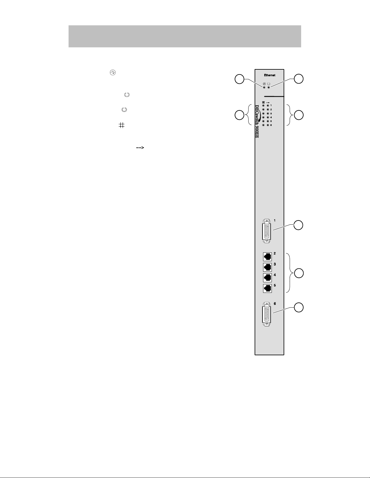
Front Panel
1) Power
LED — Lights when the module has
power.
2) Module OK
LED — Lights when the module
passes self-test. If the module fails self-test, the Module OK LED remains off.
3) Port State
LEDs — Show the status of ports 1
to 6. The LEDs can be on, off, or flashing.
4) Network Activity
LED — Indicates network traf-
fic level. The color of the LED (green or yellow) indicates whether the specific port’s network connection
is through the front panel (green) or through the
backplane (yellow).
NOTE: For more information about the
module’s LEDs, refer to the section
titled LED Descriptions.
5) 802.3/Ethernet AUI (15-pin D-Sub) port connec-
tors. — Refer to the OPEN DECconnect Applica-
tions Guide for a list of AUI media adapters you can
use with your module.
6) 10BaseT (8-pin MJ) port connectors — Supports
both UTP and STP cabling.
5
3 4
2
1
5
6
LKG-9549-94I

LKG-8709-93I
7
1
2
3
8
4
5
6
4
DECswitch 900EE Installation
Back Panel
1) Locking tab — Locks the module into a DEChub 900
backplane or into the DEChub ONE docking station.
It also contains the hot-swap switch lever.
2) 48-pin connector — Provides network and power
connections to the module when the module is
installed into a DEChub 900 or DEChub ONE docking station.
3) Grounding bolt — Provides a chassis grounding
connection between the module and a DEChub 900
or a DEChub ONE docking station.
4) Manufacturing label — Lists the module part number, serial number , revision level, and power requirements.
5) 160-pin connector — Provides network and power
connections to the module when the module is
installed into a DEChub 900 or a DEChub ONE docking station.
6) Mounting tab — Secures the module to the backplane when the module is installed into a DEChub 900
or a DEChub ONE docking station.
7) Grounding fingers — Provides additional chassis
grounding between the module and a DEChub 900
or a DEChub ONE docking station.
8) Address Label – Represents the lowest of six consecutive Media Access Control (MAC) addresses.
For example, if this module’s port 1 MAC address is
08–00–2B–AB–0C–08, then the consecutive port
MAC addresses are:
Port 1 = 08–00–2B–AB–0C–08
Port 2 = 08–00–2B–AB–0C–09
Port 3 = 08–00–2B–AB–0C–0A
Port 4 = 08–00–2B–AB–0C–0B
Port 5 = 08–00–2B–AB–0C–0C
Port 6 = 08–00–2B–AB–0C–0D
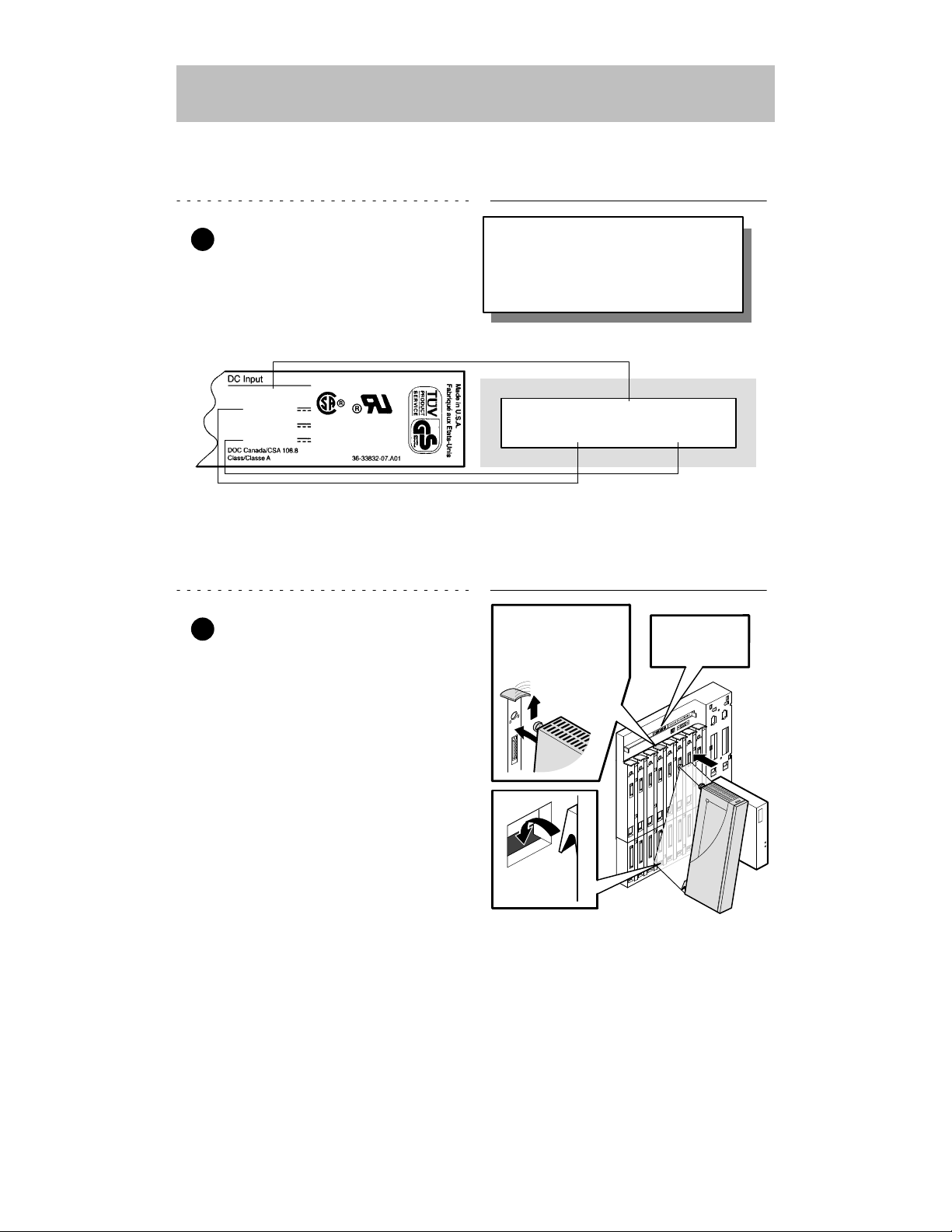
Module’s Manufacturing
Label (Example)
If any of the module’s power requirements
exceed the values shown in the status
display, add another power supply (see
the DEChub 900 MultiSwitch Owner’s
Manual).
Hub Manager Status
Display (Example)
LKG-9643-94I
Available: 90.5 W
5V: 13.0 A, 15V: 3.5 A
62.5 W
5 V
12 V
15 V
8.0 A
0.1 A
1.5 A
5
DECswitch 900EE Installation
Installing the Module
The DECswitch 900EE hot-swap feature allows you to install the module into the
DEChub 900 or DEChub ONE docking station without turning off power . Seating the
module initiates the module powerup sequence if enough power is available.
1 Compare your module’s power
requirements with the values
shown in the Hub Manager status
display (see example).
NOTE: The 12V power in the DEChub 900 is derived from the
15V power source. Although it is listed separately in the
product specifications, the 12V requirements are
included in the 15V power total.
2 Seat the module into the
DEChub 900.
a. Place the module’s mounting
tab into a mounting slot on the
DEChub 900.
b. Pivot the module on the mount-
ing tab and align the connectors.
c. Firmly push the module onto the
backplane connectors until the
release lever clicks.
d. Press down on the release lever
to ensure that it is locked.
Mounting tab
LKG–8711–93I
Release lever clicks
when module is
seated.
Hub Manager
status display
6
DECswitch 900EE Installation
Installing the Module (Cont.)
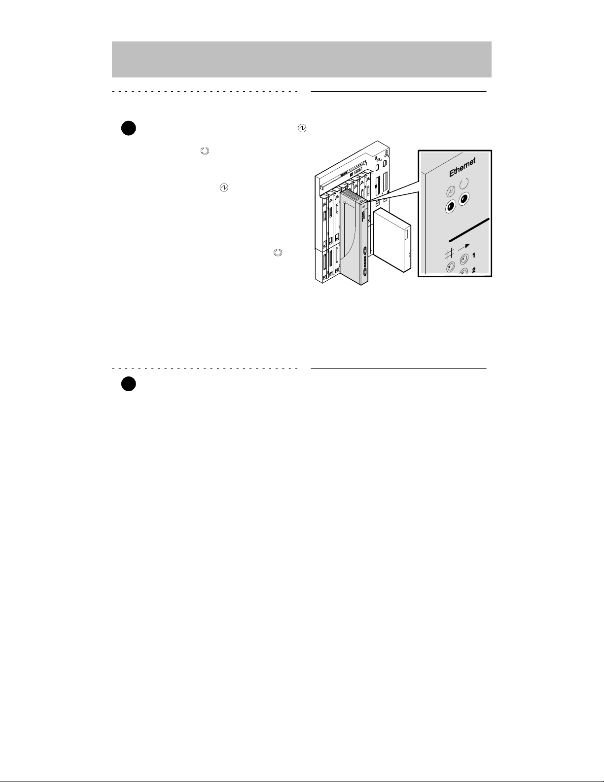
3 Verify that the module’s Power
LED lights immediately , and that the
Module OK
LED lights (within 1
minute).
a. The Power LED lights
when power is applied, then
the module performs a selftest.
b. After the module completes
self-test, the Module OK
LED lights and remains lit,
then the Hub Manager status
display shows:
DECswitch 900EE
up
NOTE: If the LEDs do not operate as described, refer to the
section titled Problem Solving Using the LEDs.
4 Connect the port cables.
Depending on your network configuration requirements, connect the appropriate
AUI cables and UTP/STP cables. After all cables are connected, go to the section
titled Configuring the Module.
See your network manager if you are not sure which cables to connect.
NOTE: All cables should be installed, tested, and tagged at the
site, prior to this installation.
• To connect AUI cables, go to step 5.
• To connect UTP/STP cables, go to step 6.
LKG-9658-94I
7
DECswitch 900EE Installation
Installing the Module (Cont.)
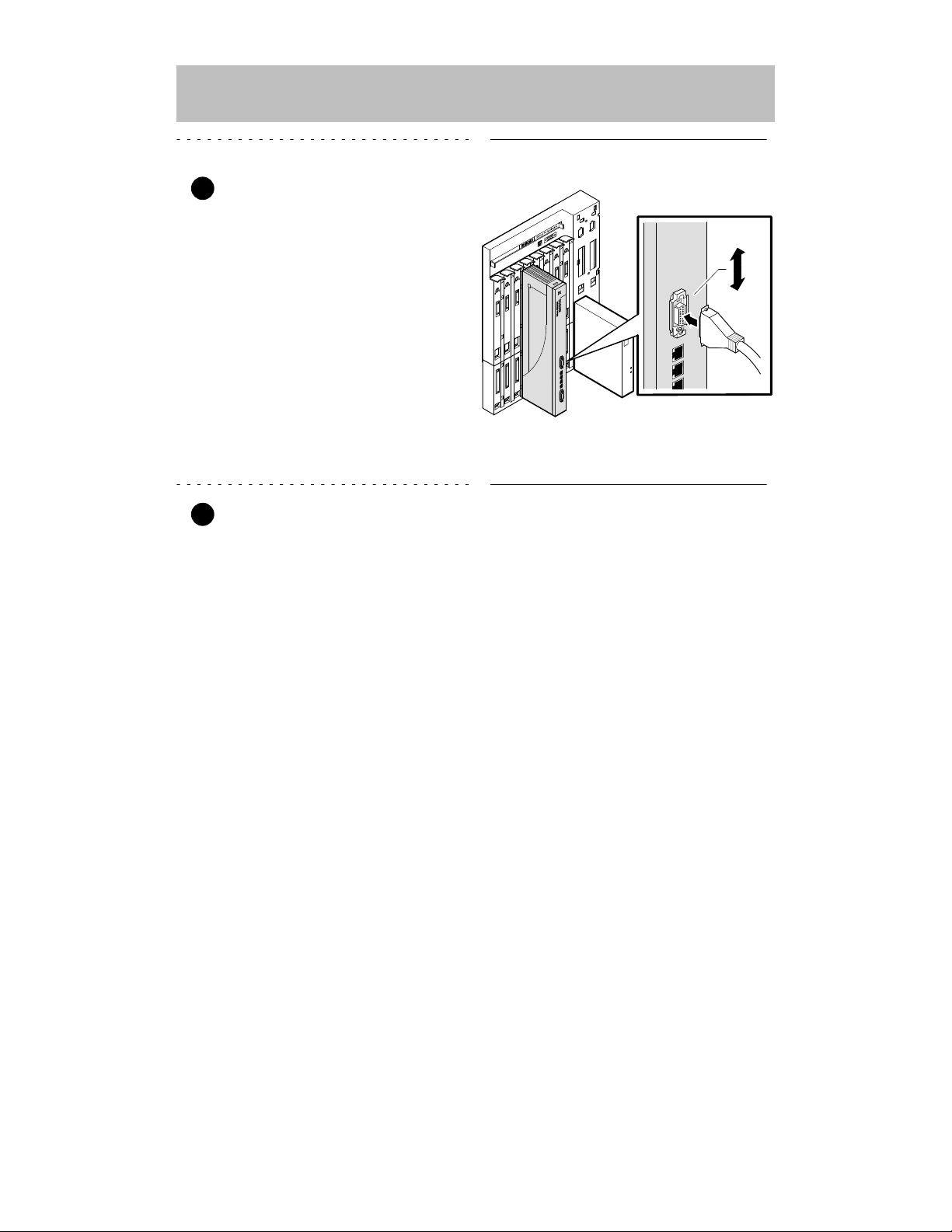
5 Connect the AUI cables.
a. Push the module’s AUI con-
nector slide latch to the unlocked position.
b. Insert the AUI cable plug into
the AUI connector.
c. Push the module’s AUI con-
nector slide latch to the
locked position.
NOTE: To disconnect the cables, push the connector slide latch
to the unlocked position, then disconnect the cable.
6 Connect the UTP/STP cables.
The DECswitch 900EE module uses straight-through 10BaseT (8-pin MJ) port
connectors. The appropriate UTP/STP cable type, crossover or straight-through, is
required to ensure that the module’s transmit/receive signals connect correctly to the
transmitter/receiver of the connected device.
Before connecting the cables to the module, note the following:
• If the device you are connecting to the module uses straight-through connectors,
use crossover cables.
• If the device you are connecting to the module uses crossover connectors, use
straight-through cables.
• The sum of crossovers must always equal an odd number.
NOTE: Digital’s straight-through cables are marked (=);
crossover connectors (and cables) are marked (X).
If you need help determining the appropriate cable type to use, refer to the section titled
Connector Pin Assignments.
LKG-9659-94I
Unlocked
Locked
8
DECswitch 900EE Installation
Installing the Module (Cont.)
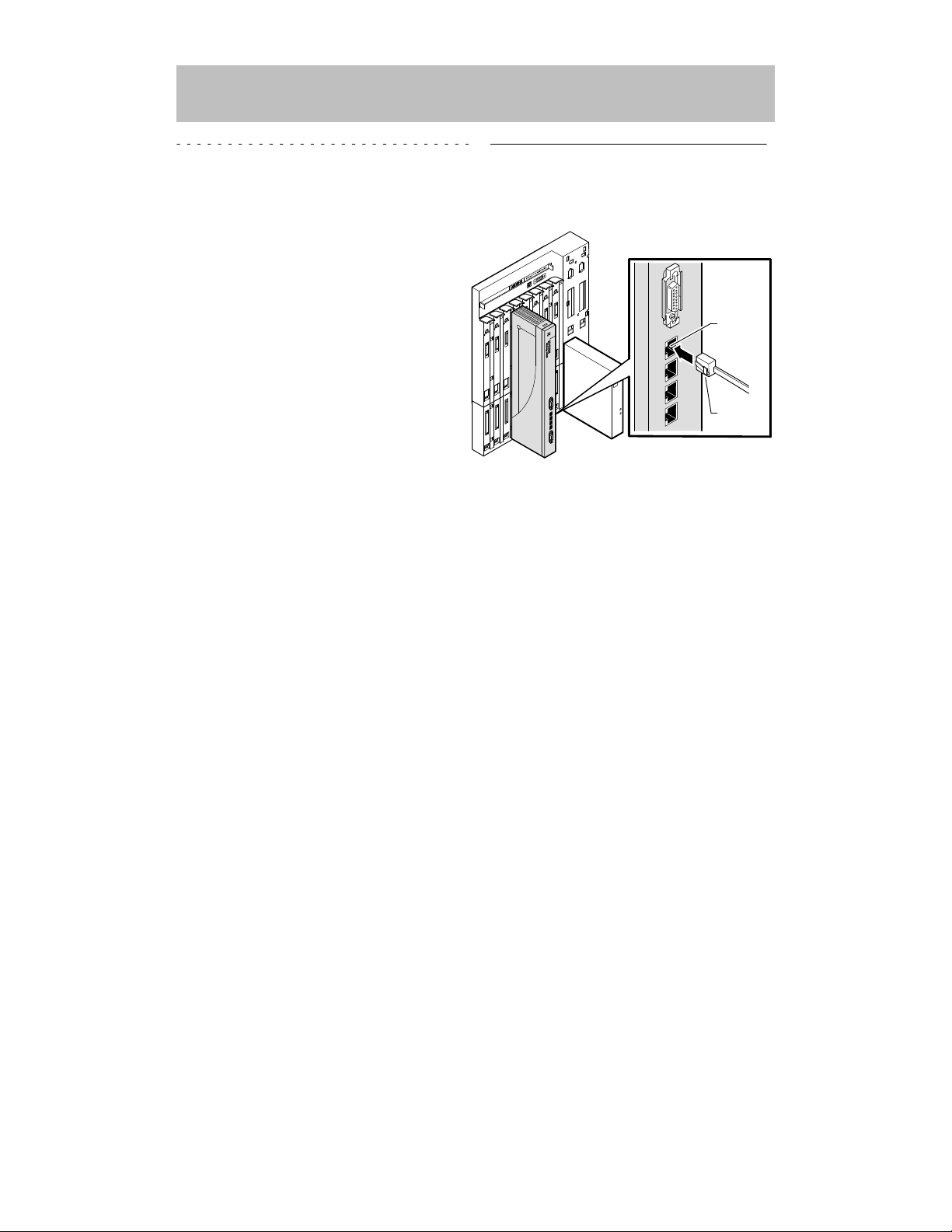
To connect the UTP/STP cables, complete the following steps:
a. Align the release tab on the
cable plug with the keyway on
the module’s 10BaseT port
connector.
b. Insert the plug into the con-
nector, ensuring that the release tab snaps into the
locked position.
NOTE: To disconnect the UTP/STP cables, press the release tab.
After all cables are installed, go to the section titled Configuring the Module.
LKG-9660-94I
Keyway
Release
tab
9
DECswitch 900EE Installation
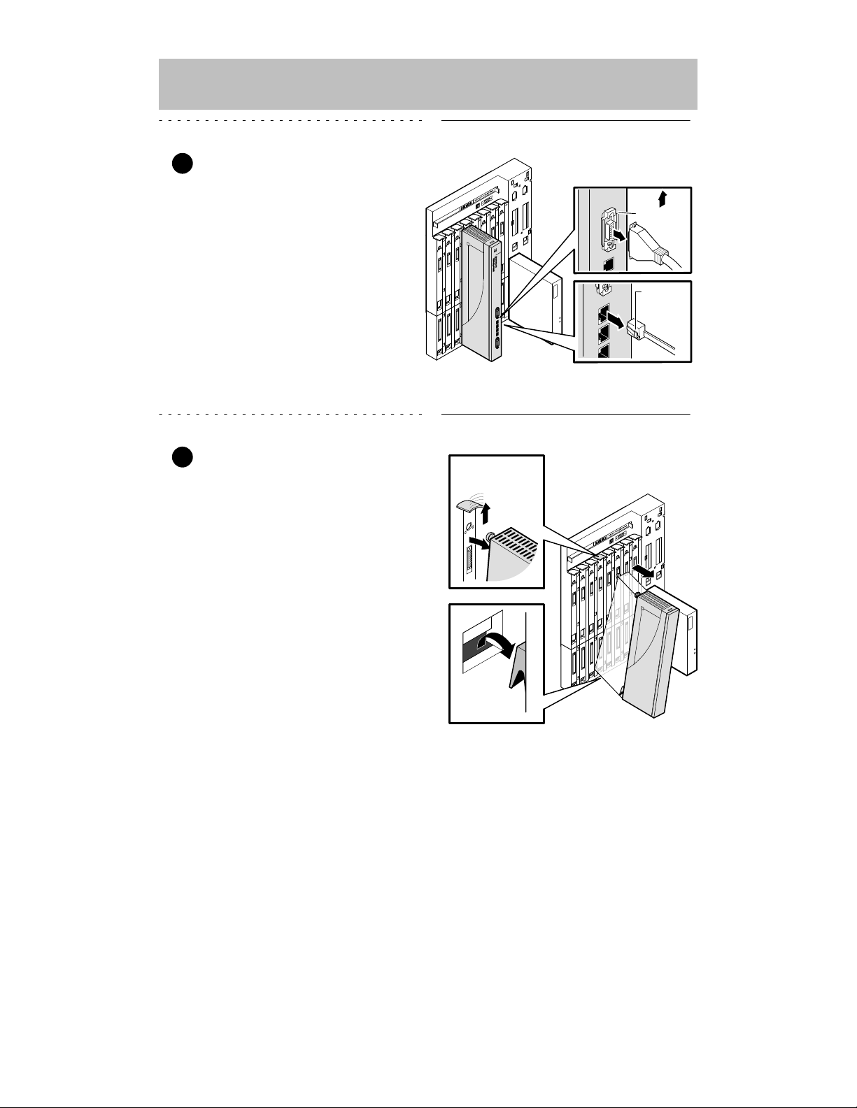
Removing the Module
1 Disconnect all the cables from
the module.
To disconnect:
a. AUI cables, push the connec-
tor slide latch to the unlocked
position, then disconnect the
cable.
b. UTP/STP cables, press the
release tab on the cable plug,
then disconnect the cable.
2 Unseat the module from the
DEChub 900.
a. Lift the release lever located
on the top of the DEChub 900
slot.
b. Pivot the module back on its
bottom mounting tab, and
disengage the module from
the backplane.
LKG-9661-94I
Unlocked
Release
tab
Mounting tab
LKG–8717-93I
Lift release lever

10
DECswitch 900EE Installation
Configuring the Module
Setup Port Description
The setup port (on the DEChub 900 MultiSwitch or the DEChub ONE) allows you to
access and set DECswitch 900EE parameters. This section describes how to access
the module from either the DEChub 900 or the DEChub ONE.
NOTE: The setup port screen displays illustrated in this manual
may vary slightly from the actual screen displays on your
setup port device.
The signals from the DEChub 900 Hub Manager setup port and from the DEChub
ONE setup port conform to the EIA-232D signaling standard at 9600 baud. To the
user, the port appears as a data terminal equipment (DTE) device.
NOTE: Devices that use the EIA-423 signaling standard are
compatible with the DEChub 900 Hub Manager setup
port.
Setup Port Device Cabling
The setup port on the DEChub 900 MultiSwitch or the DEChub ONE can be
connected to a setup port device (a terminal or personal computer), using the
following cables and adapters.
Cable/Adapter Type
Connecting Device
BN24H-xx
1
A terminal with a 6-pin MMJ connector
BN24H-xx1/H8575-A A terminal with a 25-pin D-Sub connector
BN24H-xx1/H8571-J
A PC with a 9-pin D-Sub communications port
1
xx indicates cable length in meters.
Accessing the Setup Port
To access the setup port on the DECswitch 900EE module, do the following:
1. Ensure that the transmit and receive baud rates on the setup port device are
set to 9600 baud.
2. Connect the setup port device to the setup port connector on either the
DEChub 900 or the DEChub ONE (see illustration).
 Loading...