

Digital Equipment DECstation 5000 Model 200 Operator's Manual

DECstation 5000
Model 200
HardwareOperator’sGuide
EK-366AA-OG-002
digital equipment corporation
maynard, massachusetts

First printing, April 1990
Second printing, October 1990
The information in this document is subject to change without notice and should
not be construed as a commitment by Digital Equipment Corporation. Digital
Equipment Corporation assumes no responsibility for any errors that may appear
in this document.
The software described in this document is furnished under a license and may be
used or copied only in accordance with the terms of such license.
Digital Equipment Corporation assumes no responsibility for the use or reliability
of its software on equipment that is not supplied by Digital or its affiliated
companies.
© Digital Equipment Corporation 1990.
All Rights Reserved
Printed in U.S.A.
U.S.A.
This equipment generates, uses, and may emit radio frequency energy. The
equipment has been type tested and found to comply with the limits for a Class
A computing device pursuant to Subpart J of Part 15 of FCC Rules, which
are designed to provide reasonable protection against such radio frequency
interference. Operation of this equipment in a residential area may cause
interference in which case the user at his own expense will be required to take
whatever measures may be required to correct the interference.
The following are trademarks of Digital Equipment Corporation:
DEC PDP VAXBI
DECnet ThinWire VAXcluster
DECstation TURBOchannel VAXstation
DECsystem ULTRIX VMS
DECUS ULTRIX-32 VT
MicroVAX UNIBUS
MicroVMS VAX
dt

Contents
Using This Guide ........................................... xiii
Part I Basic Workstation Hardware
1 Getting Started
Workstation Site Requirements ........................ 1–2
Temperature. . .................................... 1–2
Humidity ........................................ 1–2
Cleanliness . . . .................................... 1–2
Interference . . .................................... 1–3
Power ........................................... 1–3
Supplies ......................................... 1–3
Workstation Voltage Requirements. . .................... 1–4
The Parts of a Basic DECstation 5000 Model 200
Workstation ......................................... 1–4
2 System Unit, Monitor, Keyboard, and Mouse or Tablet
The System Unit . .................................... 2–2
Connectors, Controls, and Indicator Lights on the
System Unit . . .................................... 2–2
Inside the System Unit ............................ 2–4
The Monitor ......................................... 2–7
Connectors, Controls, and Indicator Lights on the
Monitors ......................................... 2–7
Connecting the Monitor to the System Unit ........... 2–13
iii

The Keyboard . . . .................................... 2–19
Adjusting the Keyboard ............................ 2–20
The Mouse and Tablet ................................ 2–22
Cleaning the Mouse .................................. 2–23
Connecting the Keyboard and Mouse or Tablet to the
System Unit ......................................... 2–24
Connect the Cable Assembly to the System Unit....... 2–25
Position the Connector Block Next to the Monitor. . . . . . 2–26
Connect the Keyboard to the Connector Block ......... 2–27
Connect the Mouse or Tablet to the Connector Block . . . 2–28
Supplying Power to the System Unit and Monitor ........ 2–29
Connect the Monitor-to-System-Unit Power Cable or the
Monitor Power Cord . . . ............................ 2–30
Connect the System Unit Power Cord ................ 2–32
3 Ethernet Hardware for the Basic Workstation
Terminating ThinWire Ethernet ........................ 3–2
Connecting ThickWire Ethernet Loopback Connectors . . . . . 3–4
Part II Optional Hardware
4 Internal Hardware Options
Removing and Replacing the System Unit Cover.......... 4–2
Installing and Removing Memory Modules ............... 4–5
Adding and Removing Option Modules .................. 4–12
Installing and Removing Option Modules ................ 4–15
Testing a new option module.................. 4–21
5 External Storage Options: Hard Disk, Floppy Disk,
Tape, and Optical Compact Disc Drives
Installing External Storage Devices . .................... 5–4
Set Up Your Expansion Boxes . . . .................... 5–4
Set the SCSI Switches for Each Device ............... 5–6
Connect Expansion Boxes to the System Unit ......... 5–9
Turn On Expansion Boxes and Check Configuration
Displays ......................................... 5–15
Installing a Device in a BA42 Storage Expansion Box . . . . . 5–17
Using External Storage Devices ........................ 5–17
iv

6 Optional Network Connections: ThinWire and
ThickWire Ethernet
Finding Your Ethernet Station Address.................. 6–3
Connecting the Workstation to an Ethernet Network . . . . . . 6–4
Connecting to a ThinWire Network .................. 6–4
For a workstation at the end of a ThinWire cable
segment ................................... 6–5
For a workstation within a ThinWire cable
segment ................................... 6–7
Connecting to ThickWire Networks . .................... 6–9
7 External Communication Options: Printers, Plotters,
Modems, and Console Terminals
Installing a Device That Has a 25-Pin Connector ......... 7–3
Installing a Device That Has a Telephone-Jack Type of
Connector ........................................... 7–6
Part III Testing Hardware
8 Starting and Testing Workstation Hardware
Turning On Your Workstation .......................... 8–2
Testing Your Workstation . . ............................ 8–9
Run the System Self-Test........................... 8–9
Checking Your Configuration Displays................... 8–10
Turning Off Your Workstation .......................... 8–13
9 Troubleshooting
Using Self-Tests . . .................................... 9–2
The Power-Up Self-Test ............................ 9–3
The System Self-Test . . ............................ 9–3
Reading Self-Test Results .......................... 9–4
Interpreting Error Messages Displayed on the
Screen . .................................... 9–4
Interpreting Diagnostic Indicator Lights on the
System Unit ................................ 9–15
Solving Basic Hardware Problems . . .................... 9–17
Contacting Your Digital Service Representative ........... 9–25
v

10 Using the Console Program
Console and Operating Modes.......................... 10–2
Using Console Mode . . . ............................ 10–2
Console prompts ............................ 10–2
Using Operating Mode . ............................ 10–3
Operating system prompts.................... 10–3
Entering Console and Operating Modes . . . ........... 10–3
Console mode . . . ............................ 10–3
Operating mode . ............................ 10–3
Rules for Typing Console Commands.................... 10–4
Conventions Used in This Chapter. . .................... 10–5
Console Command Formats and Functions ............... 10–6
Console Command Description ......................... 10–8
? Command . . .................................... 10–8
boot Command.................................... 10–8
cat Command. .................................... 10–9
cnfg Command.................................... 10–10
d Command . . .................................... 10–11
e Command . . .................................... 10–12
erl Command . .................................... 10–13
go Command . .................................... 10–13
init Command .................................... 10–13
ls Command . . .................................... 10–14
passwd Command ................................. 10–14
printenv Command ................................ 10–15
restart Command ................................. 10–15
script Command .................................. 10–15
setenv Command.................................. 10–15
sh Command . .................................... 10–16
t Command . . .................................... 10–17
unsetenv Command . . . ............................ 10–17
Environment Variables ................................ 10–18
Console Autoconfiguration . ............................ 10–20
11 Moving the DECstation 5000 Model 200 Workstation
Dismantling Your Workstation ......................... 11–2
Packing Your Equipment . . ............................ 11–3
Reinstalling Your DECstation 5000 Model 200. ........... 11–3
vi

Part IV Appendixes
A Equipment Specifications
B Part Numbers
C Connector Pin Assignments
Index
Figures
1-1 Voltage labels ......................................... 1–4
1-2 The parts of the basic DECstation 5000 Model 200
workstation .......................................... 1–5
2-1 The back of the system unit ............................ 2–2
2-2 Icons on the system unit . . . ............................ 2–4
2-3 Removing the cover from the system unit ................. 2–5
2-4 The inside of the system unit ........................... 2–6
2-5 Icons on the monitors .................................. 2–7
2-6 The 19-inch VR262 gray-scale monitor ................... 2–8
2-7 The 16-inch VR297 color monitor ........................ 2–9
2-8 The 19-inch VR299 color monitor ........................ 2–10
2-9 The 19-inch VRT19 color monitor ........................ 2–11
2-10 Video cable assemblies ................................. 2–13
2-11 On/off switches on the monitors ......................... 2–14
2-12 Connecting a video cable to the system unit............... 2–15
2-13 Connecting a video cable assembly to a color monitor....... 2–17
2-14 Connecting a video cable assembly to a VR262 19-inch
gray-scale monitor. .................................... 2–18
2-15 The keyboard ......................................... 2–19
2-16 Routing the keyboard cable . ............................ 2–20
2-17 Adjusting keyboard tilt ................................ 2–21
2-18 A mouse and a tablet with its puck and stylus . ........... 2–22
2-19 Removing the tracking ball from the mouse ............... 2–23
2-20 Connecting the keyboard-mouse cable .................... 2–25
vii

2-21 Positioning the connector block.......................... 2–26
2-22 Connecting the keyboard to the connector block ........... 2–27
2-23 Connecting the mouse or tablet to the connector block...... 2–28
2-24 A monitor-to-system-unit power cable and a monitor or
system unit power cord ................................ 2–29
2-25 Connecting the monitor-to-system-unit power cable to the
system unit .......................................... 2–30
2-26 Connecting a power cord to a monitor .................... 2–31
2-27 Connecting the power cord to the system unit . . ........... 2–32
3-1 Attaching terminators to a T-connector ................... 3–2
3-2 Terminating ThinWire Ethernet ......................... 3–3
3-3 Attaching a ThickWire loopback connector ................ 3–5
4-1 Removing the cover from the system unit ................. 4–3
4-2 Using an antistatic wrist strap .......................... 4–4
4-3 A memory module . .................................... 4–5
4-4 Memory inside the system unit.......................... 4–6
4-5 Releasing the memory module bracket ................... 4–7
4-6 Installing a memory module ............................ 4–8
4-7 Releasing the memory module bracket ................... 4–10
4-8 Removing a memory module ............................ 4–11
4-9 An option module . .................................... 4–13
4-10 Option slots inside the system unit . . .................... 4–14
4-11 Installing an option module in option slot 2 ............... 4–18
4-12 Installing a low 3D graphics accelerator option module . . . . . 4–19
4-13 Installing a high 3D graphics accelerator option module . . . . 4–20
5-1 Some expansion boxes ................................. 5–2
5-2 A SCSI connector and option slots . . . .................... 5–3
5-3 Expansion box cables and an expansion box, power cord and
terminator ........................................... 5–5
5-4 Removing the SCSI-switch cover from the BA42 storage
expansion box ........................................ 5–6
5-5 Expansion box SCSI switches ........................... 5–8
5-6 Attaching a system-unit-to-expansion-box cable to a SCSI
connector on the system unit ........................... 5–9
5-7 Attaching a system-unit-to-expansion-box cable to a SCSI
connector on an expansion box .......................... 5–11
5-8 Connecting expansion boxes to other expansion boxes . . . . . . 5–12
5-9 Terminating the final expansion box . .................... 5–13
5-10 Connecting power cords ................................ 5–14
6-1 ThinWire and ThickWire connectors on the system unit . . . . 6–2
viii

6-2 Sample Ethernet station addresses . . .................... 6–3
6-3 Removing a terminator from the T-connector . . ............ 6–5
6-4 Connecting a ThinWire cable to the T-connector ........... 6–6
6-5 Removing the terminators from the T-connector ........... 6–7
6-6 Connecting ThinWire cables to a T-connector . . . ........... 6–8
6-7 A ThickWire Ethernet cable ............................ 6–9
6-8 Removing a loopback connector from a ThickWire
connector ............................................ 6–10
6-9 Connecting a ThickWire Ethernet cable to the system unit . . 6–11
7-1 Communication device connectors and an adapter.......... 7–2
7-2 Connecting a communication device directly to the system
unit ................................................. 7–4
7-3 A communications connector adapter. .................... 7–6
7-4 Using an adapter to connect a communication device to the
system unit .......................................... 7–7
8-1 Expansion box on/off switches ........................... 8–2
8-2 Brightness and contrast icons ........................... 8–3
8-3 Turning on the system unit . ............................ 8–6
8-4 Sample workstation configuration display ................. 8–10
8-5 Sample slot configuration display ........................ 8–12
9-1 The reset button on the system unit . .................... 9–2
9-2 Diagnostic indicator lights . . ............................ 9–15
Tables
1 Conventions Used in This Guide ........................ xiv
2-1 Connectors, Controls, and Indicator Lights on the System
Unit................................................. 2–3
2-2 Controls, Connectors, and Indicator Lights on the
Monitors ............................................. 2–12
5-1 SCSI Cable Lengths ................................... 5–5
5-2 SCSI ID Switch Settings . . . ............................ 5–7
9-1 Error Messages on the Monitor ......................... 9–5
9-2 Test Error Codes for Color Frame Buffer Modules.......... 9–10
9-3 Test Error Codes for the 2D Graphics Accelerator Module . . . 9–10
9-4 Test Error Codes for 3D Graphics Accelerator Modules . . . . . 9–11
9-5 Test Error Codes for SCSI Modules . . .................... 9–11
9-6 Test Error Codes for Ethernet Controller Modules ......... 9–12
9-7 Test Error Codes for Base System Modules ............... 9–12
ix

9-8 Interpreting Diagnostic Indicator Lights on the System
Unit................................................. 9–16
9-9 Solutions to Basic Hardware Problems ................... 9–17
10-1 Console Command Functions ........................... 10–7
10-2 Console Commands for Environment Variables . ........... 10–18
10-3 Environment Variables Set by the User .................. 10–19
A-1 System Unit Description . . . ............................ A–2
A-2 System Unit Specifications . ............................ A–2
A-3 System Unit Operating Conditions. . . .................... A–2
A-4 System Unit Nonoperating Conditions.................... A–2
A-5 VR262 Monitor Description . ............................ A–3
A-6 VR262 Monitor Specifications ........................... A–3
A-7 VR262 Monitor Operating Conditions .................... A–4
A-8 VR262 Monitor Nonoperating Conditions ................. A–4
A-9 VR297 Monitor Description . ............................ A–5
A-10 VR297 Monitor Specifications ........................... A–5
A-11 VR297 Monitor Operating Conditions .................... A–6
A-12 VR297 Monitor Nonoperating Conditions ................. A–6
A-13 VR299 Monitor Description . ............................ A–7
A-14 VR299 Monitor Specifications ........................... A–7
A-15 VR299 Monitor Operating Conditions .................... A–8
A-16 VR299 Monitor Nonoperating Conditions ................. A–9
A-17 VRT19 Monitor Description . ............................ A–10
A-18 VRT19 Monitor Specifications ........................... A–10
A-19 VRT19 Monitor Operating Conditions .................... A–11
A-20 VRT19 Monitor Nonoperating Conditions ................. A–11
A-21 LK201 Keyboard Description............................ A–12
A-22 LK201 Keyboard Specifications .......................... A–12
A-23 LK201 Keyboard Operating Conditions ................... A–12
A-24 LK201 Keyboard Nonoperating Conditions ................ A–13
A-25 VSXXX-AA Mouse Description .......................... A–14
A-26 VSXXX-AA Mouse Specifications ........................ A–14
A-27 VSXXX-AA Mouse Operating Conditions.................. A–14
A-28 VSXXX-AA Mouse Nonoperating Conditions............... A–15
A-29 VSXXX-AB Tablet Description .......................... A–16
A-30 VSXXX-AB Tablet Specifications ......................... A–16
A-31 VSXXX-AB Tablet Operating Conditions .................. A–17
A-32 VSXXX-AB Tablet Nonoperating Conditions ............... A–17
A-33 RZ55 SCSI Hard Disk Drive Description ................. A–18
x

A-34 RZ55 SCSI Hard Disk Drive Specifications................ A–18
A-35 RZ55 SCSI Hard Disk Drive Operating Conditions ......... A–19
A-36 RZ55 SCSI Hard Disk Drive Nonoperating Conditions . . . . . . A–19
A-37 RZ56 SCSI Hard Disk Drive Description ................. A–20
A-38 RZ56 SCSI Hard Disk Drive Specifications................ A–20
A-39 RZ56 SCSI Hard Disk Drive Operating Conditions ......... A–21
A-40 RZ56 SCSI Hard Disk Drive Nonoperating Conditions . . . . . . A–21
A-41 RZ57 SCSI Hard Disk Drive Description ................. A–22
A-42 RZ57 SCSI Hard Disk Drive Specifications................ A–22
A-43 RZ57 SCSI Hard Disk Drive Operating Conditions ......... A–23
A-44 RZ57 SCSI Hard Disk Drive Nonoperating Conditions . . . . . . A–23
A-45 TK50Z Tape Drive Description .......................... A–24
A-46 TK50Z Tape Drive Specifications ........................ A–24
A-47 TK50Z Tape Drive Operating Conditions ................. A–24
A-48 TK50Z Tape Drive Nonoperating Conditions . . . ........... A–25
A-49 TLZ04 Tape Drive Description .......................... A–26
A-50 TLZ04 Tape Drive Specifications ........................ A–26
A-51 TLZ04 Tape Drive Operating Conditions.................. A–26
A-52 TLZ04 Tape Drive Nonoperating Conditions............... A–26
A-53 RRD40 Compact Disc Drive Description (Tabletop) ......... A–27
A-54 RRD40 Compact Disc Drive Specifications (Tabletop) ....... A–27
A-55 RRD40 Compact Disc Drive Operating Conditions
(Tabletop) ............................................ A–27
A-56 RRD40 Compact Disc Drive Nonoperating Conditions
(Tabletop) ............................................ A–27
B-1 Basic Components . .................................... B–2
B-2 Cords, Cables, and Connectors .......................... B–3
B-3 Software Documentation . . . ............................ B–4
B-4 Hardware Documentation . . ............................ B–5
C-1 SCSI Cable Connector Pin Assignments .................. C–2
C-2 Keyboard and Mouse or Tablet Connector Pin
Assignments.......................................... C–3
C-3 Communications Connectors Pin Assignments . . ........... C–4
C-4 ThickWire Ethernet Connector Pin Assignments ........... C–5
C-5 Summary of Loopback Connectors . . . .................... C–5
C-6 Power Supply Pin Assignments ......................... C–6
C-7 Modem Loopback Connector Pin Assignments . . ........... C–6
C-8 Ethernet Loopback Connector Pin Assignments . ........... C–6
xi

Using This Guide
Use this guide to learn to operate and troubleshoot your
DECstation 5000 Model 200 hardware.
This guide tells you
How to use the connectors and controls and interpret the
indicator lights on your workstation hardware
How to adjust your workstation hardware for your comfort
What options you can add to improve workstation
performance
How to use console commands
How to interpret the results of the power-up self-test and
the system self-test
How to read the configuration displays
How to diagnose and solve basic hardware problems
How to dismantle your workstation in preparation for
moving
What the specifications are for your workstation
components
What the part numbers are for the components of your
workstation
What the pin assignments are for your workstation cables
and connectors
xiii

Table 1. Conventions Used in This Guide
Convention Use
Monospace type Anything that appears on your monitor is
set in monospace in the text and looks like
this.
Boldface type Anything you are asked to type is set in boldface
in the text and looks like this.
Important: Type console commands exactly as they
appear in the text. The workstation does not recognize
uppercase and lowercase letters as the same input.
xiv

Part I
Basic Workstation Hardware

Getting Started
This chapter tells you
What site requirements must be met so your hardware can
operate efficiently and safely
How to check the voltage requirements of the devices that
make up your workstation
What parts make up the basic DECstation 5000 Model 200
workstation
1
Getting Started 1–1

Workstation Site Requirements
For your DECstation 5000 Model 200 workstation to function
efficiently, your work environment must meet the requirements
listed here.
Caution: Failure to meet these requirements can damage equipment.
Temperature
Keep the temperature around the workstation between 50
and 104 degrees Fahrenheit (10 and 40 degrees Celsius).
– Set up your workstation away from heaters,
photocopiers, and other sources of heat.
– Protect your workstation from sunlight.
Allow air to flow freely around your workstation to keep
heat from building up and damaging your equipment.
– Leave 4 inches (10 cm) of space between system unit
vents and other objects.
– Leave 3 inches (8 cm) of space between monitor vents
and other objects.
Humidity
Keep relative humidity within the range of 10 to 80 percent.
Cleanliness
Keep your work area as dust-free as possible.
1–2 Getting Started

Interference
Set up your workstation at least 30 inches (90 cm) away
from other terminals or monitors and from other sources
of electrical interference, such as printers or electric pencil
sharpeners.
Limit exposure to static electricity and magnetized objects
by setting up your workstation away from busy corridors
and other high-traffic areas and away from filing cabinets
and steel beams in walls.
Power
Provide a 15-ampere branch circuit for the exclusive use of
your workstation.
Be sure your electrical circuit is properly grounded and free
from electrical noise.
Be sure the voltage for workstation devices matches that of
your power source.
Supplies
Store supplies, such as tape cartridges, within the same
temperature and humidity limits as those for your
workstation.
Getting Started 1–3
Workstation Voltage Requirements
The voltage for many devices, including most monitors, must
match that of your power source. Your power source is either
110/120 or 220/240 volts. Where necessary, a yellow voltage
label that covers the power connector on your device tells you
the voltage requirements for that device.
Caution: Connecting a device to a power source that does not meet
the voltage requirements of that device can damage the device.
V 100-120
Figure 1-1. Voltage labels
V 220-240
36-17905-19
V 100-120
V 220-240
36-17905-19
WSE2I021
The Parts of a Basic DECstation 5000 Model 200 Workstation
In addition to the documentation you are reading, you should
have all the items that appear in Figure 1-2, plus your software
and any options you have ordered. Options are discussed in
Part II of this guide.
For a detailed list of items available for your workstation, see
Appendix B of this guide.
1–4 Getting Started

Getting Started 1–5
and two ThinWire terminators
One ThinWire T-connector
Screwdrivers
or other communication device
Serial cable for console terminal
Antistatic wrist strap

2
System Unit, Monitor, Keyboard, and
Mouse or Tablet
This chapter tells you
What connectors, controls, and indicator lights are present
on the system unit and monitor and what their functions
are
How to remove and replace the system unit cover
What you see when you look inside the system unit
How to connect the monitor, keyboard, and mouse or tablet
to the system unit
When to use the monitor power cord instead of the monitor-
to-system-unit power cable
How to connect the system unit power cord and the
monitor-to-system-unit power cable or the monitor power
cord
System Unit, Monitor, Keyboard, and Mouse or Tablet 2–1
The System Unit
The system unit is designed to sit flat on a level surface with
the monitor placed on top of or next to it.
Caution: Standing the system unit on its side blocks vents and can
damage the unit.
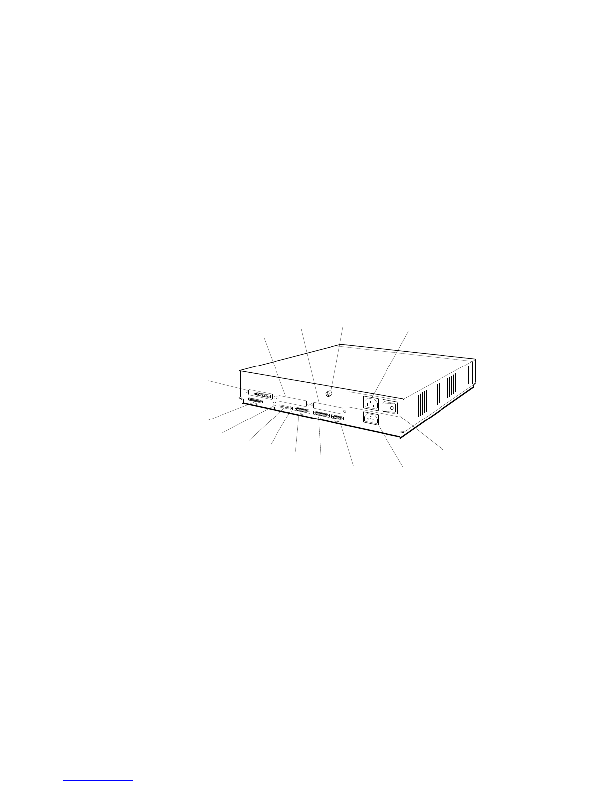
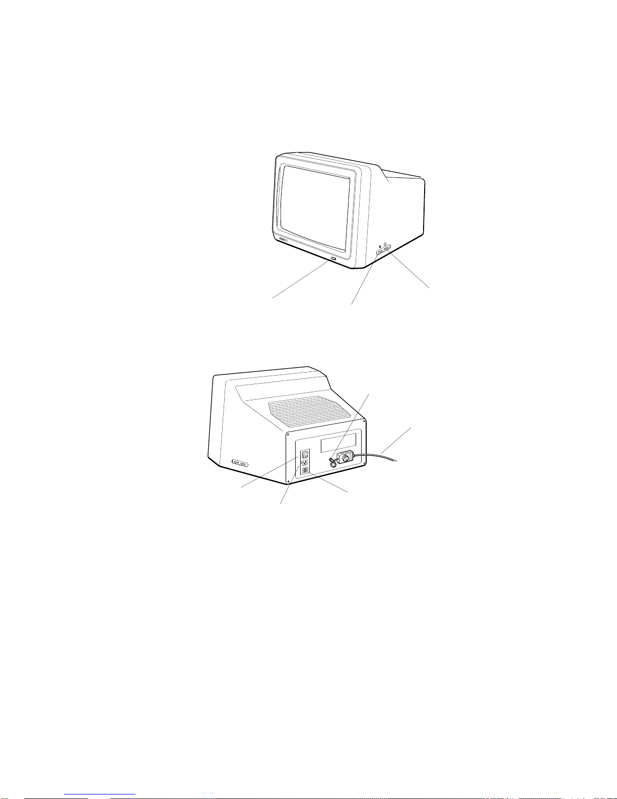
Connectors, Controls, and Indicator Lights on the System Unit
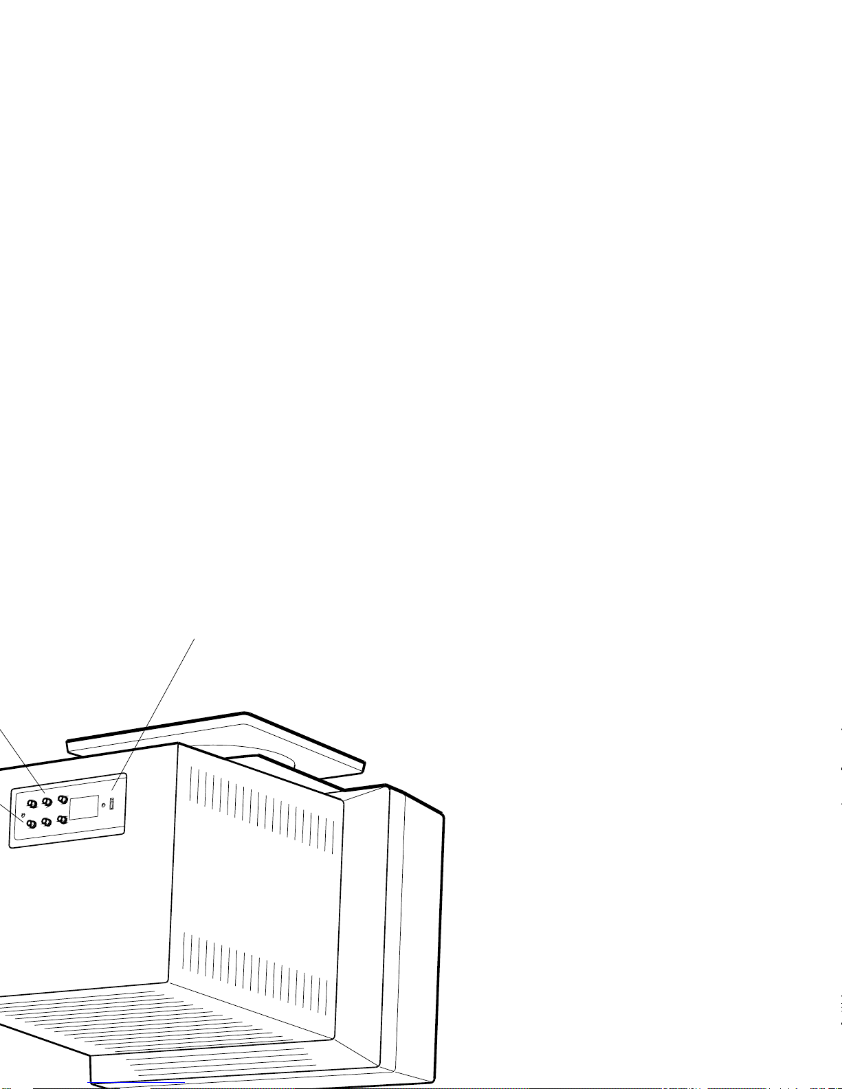
The back of the system unit contains the connectors, controls,
and indicator lights pictured in Figure 2-1 and described in
Table 2-1. Icons that appear on the system unit are pictured in
Figure 2-2.
2
3
1
0
PMAG-C
14
13
1.
Option slot 0 with a
12
11
1
10
3
2
9
video connector in place
2.
Option slot 1
3.
Option slot 2
4.
Cover-release screw
5.
Monitor-to-system-unit power connector
6.
On/off switch
7.
System unit power connector
4
V~100-120 A 3.0
V~220-240 A 1.7
2
V~100-120/220-240
A 7.9/4.2
Hz 50-60
W 359
5
6
8
8.
Keyboard-mouse connector
9.
Communications connector (baud 2)
10.
Communications connector (baud 3)
11.
Reset button
12.
Diagnostic indicator lights
13.
ThinWire Ethernet connector
14.
Small computer system interface
7
(SCSI) connector
WSE2O002
Figure 2-1. The back of the system unit
2–2 System Unit, Monitor, Keyboard, and Mouse or Tablet

Table 2-1. Connectors, Controls, and Indicator Lights on the System Unit
Item Function
Option slots 0, 1, and 2 Points at which video, SCSI, and network
options can connect to option modules in
the system unit. In Figure 2-1, option slot
0 contains a video connector, the point at
which a video cable connects the monitor to
the system unit.
Cover-release screw A captive screw that allows the cover to be
removed from the system unit.
Monitor-to-system-unit power
connector
The point at which power can pass from the
system unit to the monitor.
On/off switch Turns the system unit on and off. Pressing
the 1 turns the system unit on. Pressing
the 0 turns it off.
System unit power connector The point at which power from the power
source reaches the system unit.
Keyboard-mouse connector The point at which the keyboard-mouse
cable connects the keyboard and mouse or
tablet to the system unit.
Communications connectors The points at which communication devices,
such as modems and printers, can connect
to the system unit.
Reset button Resets the system hardware.
Diagnostic indicator lights When there is no display on the monitor,
these lights indicate where system failures
have occurred.
ThinWire Ethernet connector The point at which ThinWire Ethernet
connects to the system unit.
SCSI connector The point at which up to seven external
SCSI storage devices can connect to the
system unit.
System Unit, Monitor, Keyboard, and Mouse or Tablet 2–3

d
i
g
i
t
a
l
0
PMAG-C
1
PMAZ-A
PMAD-A
3
V~100-120 A 3.0
V~220-240 A 1.7
2
V~100-120/220-240
A 7.9/4.2
Hz 50-60
W 359
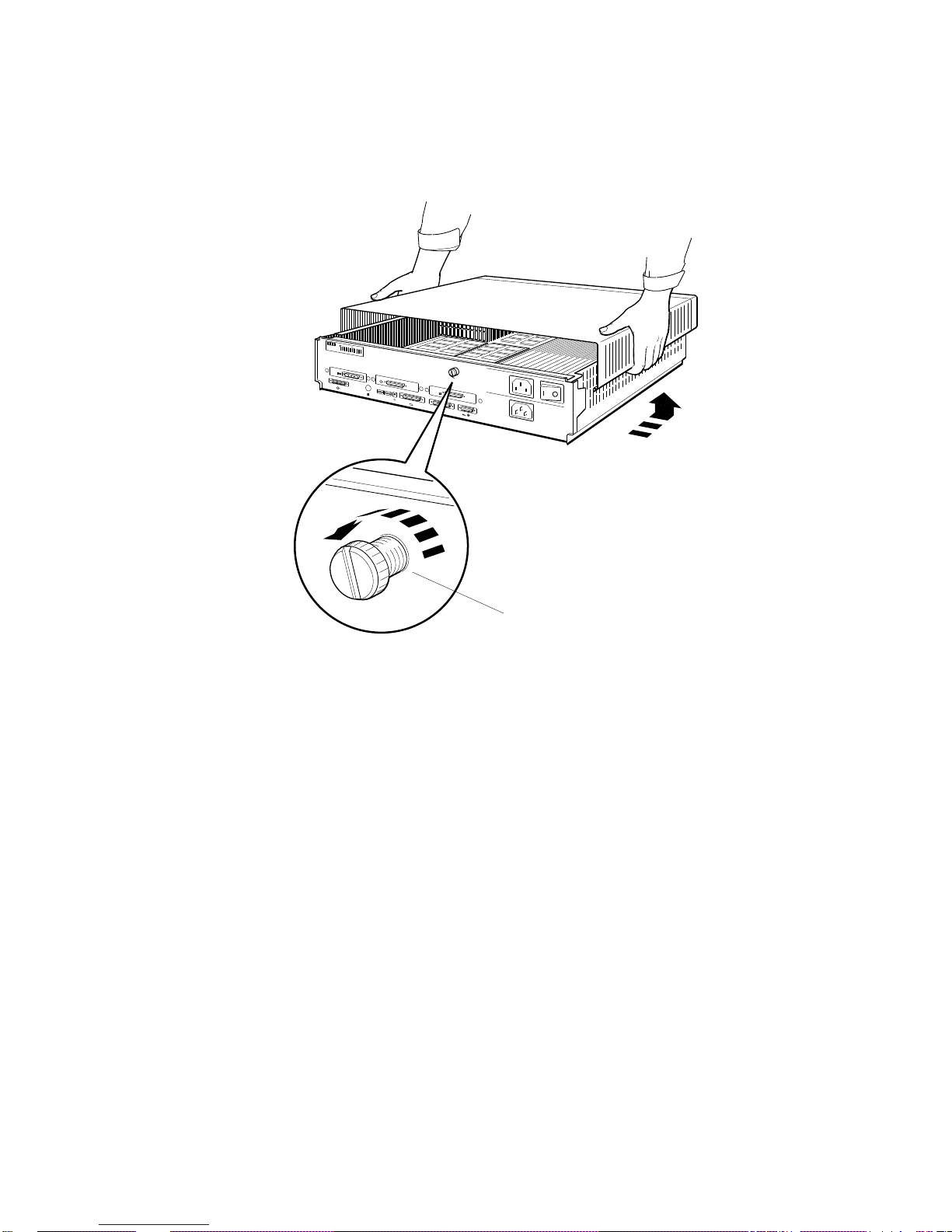
Cover-release screw
Figure 2-3. Removing the cover from the system unit
WSE2O027
System Unit, Monitor, Keyboard, and Mouse or Tablet 2–5
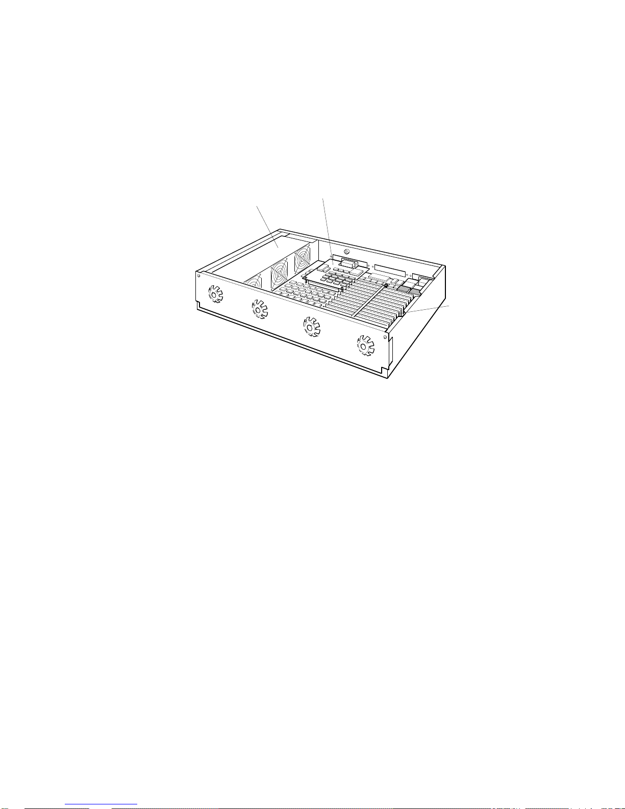
When the cover is off the system unit, you can see the power
supply and any memory and option modules inside the unit.
An option module
Power supply
Memory modules
WSE2O028
Figure 2-4. The inside of the system unit
To replace the cover on the system unit
1. Facing the front of the system unit, grasp each side of the
cover with your hands and position it so it rests on top of
the unit about 3 inches short of the back panel of the unit.
2. Move the cover straight toward the back panel of the
system unit until it slips into place on the unit.
3. Press the cover-release screw on the back of the unit toward
you and turn it to your left until it locks in place.
2–6 System Unit, Monitor, Keyboard, and Mouse or Tablet
The Monitor
Your DECstation 5000 Model 200 workstation came with one of
the following monitors:
You can tell which monitor you have by looking at the name on
the identification plate on the back of the monitor.
Connectors, Controls, and Indicator Lights on the Monitors
Connectors, controls, and indicator lights are located in
different places on different monitors. Look at the illustration
of your monitor to see where to find them.
Figure 2-5 shows the icons that appear on the monitors.
Figures 2-6 through 2-9 show the monitors. Table 2-2 describes
the connectors, controls, and indicator lights on the monitors.
19-inch VR262 gray-scale monitor
16-inch VR297 color monitor
19-inch VR299 color monitor
19-inch VRT19 color monitor
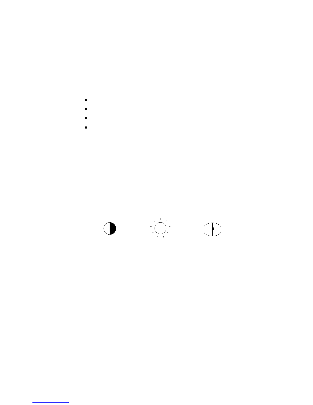
Contrast
Figure 2-5. Icons on the monitors
System Unit, Monitor, Keyboard, and Mouse or Tablet 2–7
DegaussBrightness
WSE2O004
Power indicator light
Brightness control
Contrast control
Video cable
connector
Video cable
On/off switch
Power connector
Fuse panel
Figure 2-6. The 19-inch VR262 gray-scale monitor
2–8 System Unit, Monitor, Keyboard, and Mouse or Tablet
DEPG006
Vertical static
convergence
(V-STAT) control
Horizontal static
convergence
(H-STAT) control
Vertical centering
(V-CENT) control
Contrast control
Power indicator light
RGB signal
cable connectors
Fuse
R
G
B
Power connector
Figure 2-7. The 16-inch VR297 color monitor
On/off switch
WSE2O006
System Unit, Monitor, Keyboard, and Mouse or Tablet 2–9
connectors
RGB signal cable
WSE2O007
High-scan/low-scan switch
 Loading...