

Digital Equipment DECserver 700-08, DECserver 700-16 Hardware Owner's Manual

DECserver 700
Site Preparation and Maintenance
(Hardware Owner’s Manual)
Part Number: EK-DSRVW-MG. B01

NOTICE — Class A Computing Device:
This equipment generates, uses, and may emit radio frequency energy. The equipment
has been type tested and found to comply with the limits for a Class A computing device pursuant to Subpart J of Part 15 of FCC Rules, which are designed to provide
reasonable protection against such radio frequency interference.
Operation of this equipment in a residential area may cause interference; in which
case, the user at his own expense will be required to take whatever means are neces sary to correct the interference.

DECserver 700
Site Preparation and Maintenance
(Hardware Owner’s Manual)
February 1993
This manual, in conjunction with the
Installation Card
network access server and how to verify its operation. This
manual also describes the controls and indicators. This manual
is intended for the hardware installer and the network manager.
Supersession/Update Information: This is a revised manual.
Software Version: DECserver Network Access Software V1.0
This manual applies to Version 1.0 of the DECserver Network
Access Software and all subsequent maintenance releases up
to the next major product release.
, describes how to install the DECserver 700
DECserver 700 Hardware
Part Number: EK-DSRVW-MG. B01

EK-DSRVW-MG. B01
The information in this document is subject to change without notice and should not be construed as
a commitment by Digital Equipment Corporation. Digital Equipment Corporation assumes no responsibility for any errors that may appear in this document.,
Copyright 1993 by Digital Equipment Corporation
All Rights Reserved
The following are trademarks of Digital Equipment Corporation: DEC, DECconnect, DECnet,
DECserver, DELNI, DEMPR, DESTA, ThinWire, UNIBUS, VAX, and the Digital logo.
This manual was produced by Telecommunications and Networks Publications.

Preface
Hardware Overview
1.1 Models 1–1. . . . . . . . . . . . . . . . . . . . . . . . . . . . . . . . . . . . . . . . . . . .
1.2 Controls, Indicators, and Connectors 1–3. . . . . . . . . . . . . . . . . . . . .
1.3 Understand the Software Loading 1–6. . . . . . . . . . . . . . . . . . . . . . .
1.3.1 Loading from Flash RAM 1–6. . . . . . . . . . . . . . . . . . . . . . . . . . .
1.3.2 Loading from the Network 1–6. . . . . . . . . . . . . . . . . . . . . . . . . .
Checking the Site
2.1 Physical Requirements 2–1. . . . . . . . . . . . . . . . . . . . . . . . . . . . . . . .
2.2 Environmental Requirements 2–2. . . . . . . . . . . . . . . . . . . . . . . . . . .
2.3 Electrical Requirements 2–3. . . . . . . . . . . . . . . . . . . . . . . . . . . . . . .
Contents
iii

Cabling the Site
3.1 Preinstallation Checks 3–1. . . . . . . . . . . . . . . . . . . . . . . . . . . . . . . .
3.2 Installing the Ethernet Cables and Devices 3–2. . . . . . . . . . . . . . . .
3.2.1 Installing the Standard Ethernet Cables and Devices 3–2. . . . . .
3.2.2 Installing the 10BaseT Ethernet Cables and Devices 3–4. . . . . .
3.2.3 Installing the ThinWire Ethernet Cables and Devices 3–5. . . . . .
3.3 Installing Serial Cables and Devices on the DECserver 700-16 3–9
3.4 Installing Serial Cables and Devices on the DECserver 700-08 3–11
3.5 Cabling Requirements 3–12. . . . . . . . . . . . . . . . . . . . . . . . . . . . . . . .
3.5.1 Standard Ethernet Connection 3–13. . . . . . . . . . . . . . . . . . . . . . . .
3.5.2 10BaseT Ethernet Connection 3–14. . . . . . . . . . . . . . . . . . . . . . . .
3.5.3 ThinWire Ethernet Connection 3–14. . . . . . . . . . . . . . . . . . . . . . .
3.6 Installing the DECserver 700 in a Rack 3–15. . . . . . . . . . . . . . . . . . .
Connector and Cable Pin Descriptions
4.1 Connector Pin Descriptions 4–1. . . . . . . . . . . . . . . . . . . . . . . . . . . .
4.1.1 Standard Ethernet 4–2. . . . . . . . . . . . . . . . . . . . . . . . . . . . . . . . . .
4.1.2 10BaseT Ethernet 4–3. . . . . . . . . . . . . . . . . . . . . . . . . . . . . . . . . .
4.1.3 DECserver 700-08 Serial Line Ports 4–4. . . . . . . . . . . . . . . . . . .
4.1.4 DECserver 700-16 Serial Line Ports 4–5. . . . . . . . . . . . . . . . . . .
4.2 Cable Connections 4–6. . . . . . . . . . . . . . . . . . . . . . . . . . . . . . . . . . .
Replacing and Adding Memory
5.1 Replacing a Faulty Single-In-Line Memory Module 5–1. . . . . . . . .
5.2 Additional Memory Supported 5–2. . . . . . . . . . . . . . . . . . . . . . . . .
5.3 Installing Extra Memory 5–4. . . . . . . . . . . . . . . . . . . . . . . . . . . . . .
Replacing and Adding Flash RAM
6.1 Replacing or Adding Flash RAM 6–1. . . . . . . . . . . . . . . . . . . . . . .
iv

What to Do If You Have Problems
7.1 Diagnosing DECserver 700 Problems 7–1. . . . . . . . . . . . . . . . . . . .
7.2 Seven-Segment Display Off and System OK LED Off 7–2. . . . . . .
7.3 System OK LED Off/Seven-Segment Display Flashing “C”, “d”,
or “n” 7–3. . . . . . . . . . . . . . . . . . . . . . . . . . . . . . . . . . . . . . . . . . . . .
7.4 System OK LED Off/Seven-Segment Display Flashing 7–4. . . . . .
7.5 System OK LED Flashing 7–4. . . . . . . . . . . . . . . . . . . . . . . . . . . . .
7.5.1 Error Message 952 7–5. . . . . . . . . . . . . . . . . . . . . . . . . . . . . . . . .
Figures
1–1 DECserver 700-08 Rear View 1–2. . . . . . . . . . . . . . . . . . . . . . . . . .
1–2 DECserver 700-16 Rear View 1–3. . . . . . . . . . . . . . . . . . . . . . . . . .
1–3 DECserver 700 Front End 1–3. . . . . . . . . . . . . . . . . . . . . . . . . . . . .
3–1 Standard Ethernet Coaxial Cable Connection 3–3. . . . . . . . . . . . . .
3–2 10BaseT Ethernet Connection 3–4. . . . . . . . . . . . . . . . . . . . . . . . . .
3–3 Connecting the DECserver 700 to ThinWire Ethernet Cable 3–5. .
3–4 ThinWire Ethernet Standalone Segment 3–7. . . . . . . . . . . . . . . . . .
3–5 DEMPR ThinWire Connection 3–8. . . . . . . . . . . . . . . . . . . . . . . . .
3–6 DEMPR Connections 3–9. . . . . . . . . . . . . . . . . . . . . . . . . . . . . . . . .
3–7 How to Fit the Brackets to Recess the DECserver 700 3–16. . . . . . .
3–8 Removing the Brackets 3–17. . . . . . . . . . . . . . . . . . . . . . . . . . . . . . .
4–1 Pin Numbers and Signals for Standard Ethernet Connector 4–2. . .
4–2 Pin Numbers and Signals for 10BaseT Ethernet Connector 4–3. . .
4–3 Pin Numbers and Signals for 25-Pin D-sub Connector 4–4. . . . . . .
4–4 Pin Numbers and Signals for the MJ8 Connector 4–5. . . . . . . . . . .
4–5 Adapters and Connectors Used with the DECserver 700 4–8. . . . .
5–1 Removing the Brackets 5–5. . . . . . . . . . . . . . . . . . . . . . . . . . . . . . .
5–2 Removing the Covers 5–6. . . . . . . . . . . . . . . . . . . . . . . . . . . . . . . . .
5–3 Fitting the Anti-Static Kit 5–7. . . . . . . . . . . . . . . . . . . . . . . . . . . . . .
5–4 Locating the SIMs Connectors 5–8. . . . . . . . . . . . . . . . . . . . . . . . . .
5–5 Removing a Sim 5–9. . . . . . . . . . . . . . . . . . . . . . . . . . . . . . . . . . . . .
5–6 Inserting the Replacement SIM 5–10. . . . . . . . . . . . . . . . . . . . . . . . .
5–7 Adding an Additional SIM 5–11. . . . . . . . . . . . . . . . . . . . . . . . . . . . .
v

5–8 Replacing the Covers 5–12. . . . . . . . . . . . . . . . . . . . . . . . . . . . . . . . .
6–1 Locating the Flash RAM Card Connector 6–3. . . . . . . . . . . . . . . . .
6–2 Inserting the Flash RAM Card 6–4. . . . . . . . . . . . . . . . . . . . . . . . .
Tables
1–1 DECserver 700 Controls 1–4. . . . . . . . . . . . . . . . . . . . . . . . . . . . . .
1–2 DECserver 700 Indicators 1–4. . . . . . . . . . . . . . . . . . . . . . . . . . . . .
1–3 Network Activity LED 1–5. . . . . . . . . . . . . . . . . . . . . . . . . . . . . . . .
1–4 DECserver 700 Connectors 1–5. . . . . . . . . . . . . . . . . . . . . . . . . . . .
2–1 Physical Specifications of the DECserver 700 2–1. . . . . . . . . . . . . .
2–2 Acoustics 2–2. . . . . . . . . . . . . . . . . . . . . . . . . . . . . . . . . . . . . . . . . .
2–3 Environmental Specifications of the DECserver 700 2–2. . . . . . . .
2–4 Electrical Requirements 2–3. . . . . . . . . . . . . . . . . . . . . . . . . . . . . . .
2–5 Standard Ethernet/IEEE 802.3 Connector Output 2–3. . . . . . . . . . .
3–1 Cables and Adapters for the DECserver 700-16 3–10. . . . . . . . . . . .
3–2 Cables and Adapters for the DECserver 700-08 3–11. . . . . . . . . . . .
3–3 Maximum Communications Distances — Ethernet 3–12. . . . . . . . . .
3–4 Maximum Cable Lengths1 — DECserver 700 to Devices 3–13. . . .
3–5 Installing the DECserver 700 Brackets 3–15. . . . . . . . . . . . . . . . . . .
4–1 Cable Connections 4–6. . . . . . . . . . . . . . . . . . . . . . . . . . . . . . . . . . .
7–1 Display/Indications 7–2. . . . . . . . . . . . . . . . . . . . . . . . . . . . . . . . . .
7–2 Network Activity LED 7–10. . . . . . . . . . . . . . . . . . . . . . . . . . . . . . . .
vi

Preface
Intended Audience
This manual, in conjunction with the DECserver 700 Hardwar e Installation Card, is
intended for the hardware installer. The installer is responsible for ensuring that the
hardware is installed and tested. The DECserver 700 Hardware Installation Card
shows how to install the DECserver
and devices are in place. This manual shows how to verify the site, install cables and
devices, and troubleshoot the DECserver 700. The person installing the DECserver
700 software can then verify the system installation.
Structure of This Manual
This manual contains the following chapters:
• Chapter 1 — Provides an overview of the DECserver 700 features.
• Chapter 2 — Describes how to verify the site before installing the DECserver
700.
• Chapter 3 — Describes how to cable the site.
TM
700 when the site is verified and the cables
• Chapter 4 — Describes connector pins for the various server connectors and
also describes various cables, adapters, and accessories used with the DECserver 700.
• Chapter 5 — Shows how to install extra memory and replace faulty memory .
• Chapter 6 — Shows how to update a DS700 with Flash RAM.
• Chapter 7 — Shows how to troubleshoot the DECserver 700.
vii

Associated Documents
• DECserver 700 Hardware Installation Card
Shows how to install the DECserver 700 when the site is verified and the
cables and devices are in place.
• DECserver Network Access Software Installation (op-sys)
Explains how to install the DECserver 700 distribution software, how to establish downline load hosts, and how to verify the DECserver 700 system
installation. In the title, (op-sys) is the name of the load host operating system.
• Network Access Server Problem Solving
Describes the software tools and techniques available to troubleshoot the
server and also describes all error messages.
• Network Access Server Management
Provides the procedures to perform various DECserver 700
management tasks.
• Network Access Server Commands
Lists and describes all the DECserver 700 software commands.
• DECconnect System Planning and Configuration Guide
Information on cabling and configuring of local area networks and using
DECconnect system products.
• The Ethernet: A Local Area Network: Data Link Layer and Physical Layer
Specification
Lists standard Ethernet connectors and their signal specifications.
viii
Digital Confidential

1
Hardware Overview
The DECserver 700 connects devices (such as printers, terminals, PCs, and modems) to local area networks (LANs). The DECserver 700 is Ethernet/IEEE
802.3-based and supports standard Ethernet/IEEE 802.3 and 10BaseT Ethernet/
IEEE 802.3 directly, and ThinWire
DECserver 700 can be installed on a desktop or in a 19-inch rack. The DECserver
700 supports Flash RAM capability and other nonvolatile forms of memory. This
capability can be ordered separately and installed on the DECserver 700 in the field.
The DECserver 700 can download the software image from the network or from the
Flash RAM option if installed. The Flash RAM option allows for a boot/power up
without having to download the image through the network. The DECserver 700 will
support up to 8 Mbytes of memory with the use of two single-in-line modules
(SIMs). These SIMs can be installed as memory updates by the customer.
TM
Ethernet/IEEE 802.3 through an adapter. The
There are two DECserver 700 models:
• DECserver 700-08
• DECserver 700-16
1.1 Models
The DECserver 700-08 supports EIA-232-D/V .24/V.28 full modem control on eight
25-pin male D-connectors. Use this model to connect devices that require full duplex, asynchronous control (for example: modems).
1–1
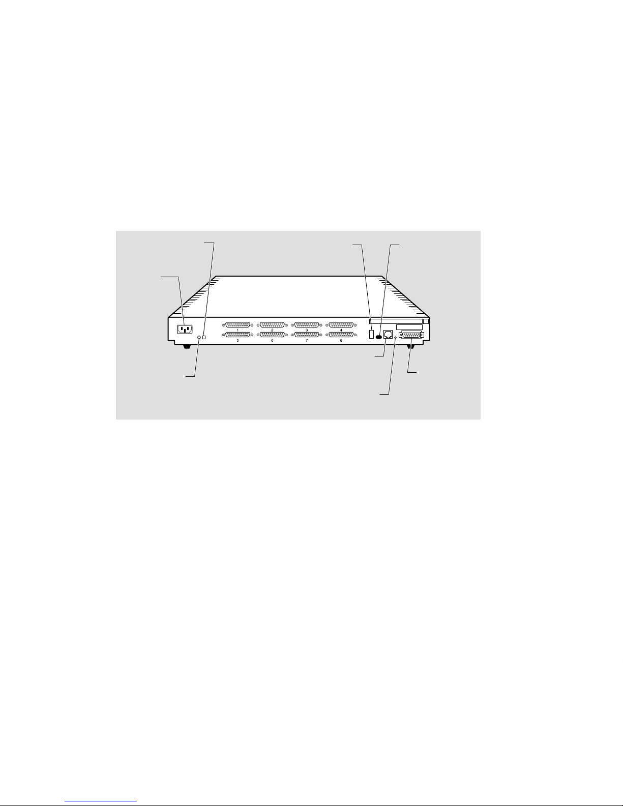
Figure 1–1 shows a rear view of the DECserver 700-08. The DECserver 700-16 supports EIA-423-A and DEC 423 data-leads on 16 MJ8 connectors. Use this model to
connect devices requiring data-leads for operation (for example: terminals, printers,
and personal computers in terminal emulation mode). You can connect the DECserver to modems that do not require the full complement of signals provided by the
DECserver 700-08, using special adapters (Section 3.3).
NOTE
Adapters H8585-AB and H8585-AC are not for connection to public networks in Sweden, Germany , or Japan.
Figure 1–1: DECserver 700-08 Rear View
System reset
switch
Power
receptacle
System
OK LED
Seven-segment
display
Serial ports
10BaseT
Ethernet
connector
Network
activity LED
Ethernet
select
switch
Standard
Ethernet
connector
LKG-5569-91I
1–2 Site Preparation and Maintenance
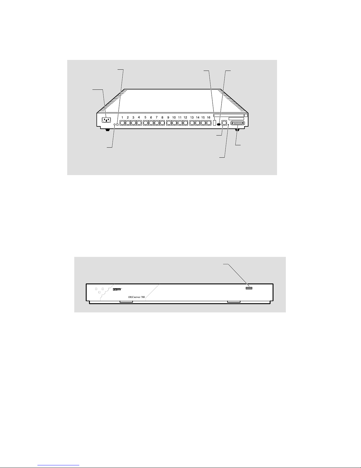
Figure 1–2 shows a rear view of the DECserver 700-16.
Figure 1–2: DECserver 700-16 Rear View
System reset
switch
Seven-segment
display
Ethernet
select
switch
Power
receptacle
Serial ports
10BaseT
System
OK LED
Ethernet
connector
Network
Standard
Ethernet
connector
activity LED
LKG-5568-91I
1.2 Controls, Indicators, and Connectors
All of the DECserver 700 controls, indicators, and connectors are located on the rear
of the DECserver 700 as shown in Figure 1–1 and Figure 1–2, with the exception of
the System OK LED, which is duplicated on the front of the DECserver 700
(Figure 1–3).
Figure 1–3: DECserver 700 Front End
System OK LED
LKG–6008–91I
1–3Hardware Overview

T able 1–1 describes the DECserver 700 controls. Table 1–2 and T able 1–3 describe
the indicators, and T able 1–4 describes the connectors. For more information on the
connectors, refer to Chapter 4.
T able 1–1: DECserver 700 Controls
Control
System reset switch On power up, press this switch until E appears on the
Ethernet select switch This switch selects either standard or 10BaseT Ethernet.
Description
seven-segment display. This reloads the factory set parameters. During Flash load, pressing and holding the
system reset switch will abort the Flash RAM load and
force a network boot. Refer to Chapter 7 for more information.
Table 1–2: DECserver 700 Indicators
Indicator
System OK LED Lights (green) when the DECserver 700 has passed self-
Network activity LED Refer to Table 1–3.
Seven-segment display Provides error and status information.
Display
test. Blinks when a nonfatal error occurs on self-test.
When off, indicates that the DECserver 700 has failed
self-test.
1–4 Site Preparation and Maintenance

Table 1–3: Network Activity LED
Ethernet
Selected
Connection Status LED Display
10BaseT Open/incorrectly terminated
Correctly terminated / no network activity
Correctly terminated / network activity
Standard Ethernet Open
Correctly connected / no network activity
Correctly connected / network activity
OFF
ON
Flashing (rate independent of
network activity)
OFF
OFF
Flashing or ON, depending
on network activity
Table 1–4: DECserver 700 Connectors
Connector
Serial port connectors
(DECserver 700-08)
Serial port connectors
(DECserver 700-16)
Standard Ethernet connector This single 15-pin female D-connector connects to a stan-
10BaseT Ethernet connector This single female MJ8 connector connects to a 10BaseT
Power cord receptacle The DECserver 700 power cord plugs into this receptacle.
Description
These eight 25-pin male D-connectors connect EIA-232-D
devices to the DECserver 700.
These 16 female MJ8 connectors connect data-lead devices to the DECserver 700.
dard Ethernet/IEEE 802.3 local area network using a
transceiver cable.
Ethernet/IEEE 802.3 local area network.
1–5Hardware Overview

1.3 Understand the Software Loading
This section describes the two methods that the DECserver 700 access to load the
software.
1.3.1 Loading from Flash RAM
Once the DECserver 700 completes self-tests, the DECserver 700 checks for Flash
RAM. If there is a valid Flash RAM, the DECserver 700 begins the boot sequence to
load the software from Flash RAM. The seven-segment display will display three
horizontal segments during this loading process.
If the DECserver 700 does not have Flash RAM, the DECserver 700 proceeds to a
network load.
If a device is connected to the console port, the DECserver 700 can display status
messages while the boot sequence is running. Status messages indicate the Ethernet
address of the DECserver 700, the name of the load image it is looking for, and the
stage of the boot process it is in.
1.3.2 Loading from the Network
If you do not want to load the software from Flash RAM, you can press the system
reset switch during load from Flash RAM. When the system reset switch is pressed,
the Flash RAM load will be aborted and the software is downline loaded from a load
host.
When the DECserver 700 notices the system reset switch depressed during load
from Flash RAM, it will rapidly blink the LED to acknowledge the pressed system
reset switch (this may take several seconds). Once the LED begins rapidly blinking,
you may release the system reset switch and the firmware will go on to a network
boot sequence. For more information on display codes for Flash RAM, refer to section 7.7.
1–6 Site Preparation and Maintenance

Checking the Site
The DECserver 700 can operate in an office environment and in a standard equipment rack located in a computer room or satellite equipment room. Regardless of
where you install the DECserver 700, verify that all of the requirements in this section are met before beginning the installation.
2.1 Physical Requirements
Allow for 15 cm (6 in) of airspace around the DECserver 700 air vents. Table 2–1
shows the size and weight of the DECserver 700. T able 2–2 shows the acoustic parameters.
2
Table 2–1: Physical Specifications of the DECserver 700
Dimension
Height 44 mm (1.73 in)
Width 442 mm (17.4 in)
Depth 282 mm (11.1 in)
Weight
Measurement
2.5 kg (5.51 lbs)
2–1

Table 2–2: Acoustics
Parameter
1
L
WAd
L
(bystander)
pAm
1
Preliminary declared values per ISO 9296 and ISO 7779. Current values are available from
Digital representatives.
1
Measurement
4.1 bels (LWA = 3.8 bels)
27 dBA
2.2 Environmental Requirements
Environmental requirements for temperature and humidity must be within the
ranges shown in Table 2–3.
Table 2–3: Environmental Specifications of the DECserver 700
Parameter
Temperature
1
Operating 5°C (41°F) 50°C (122°F)
Nonoperating – 40°C (– 40°F) 66°C (151°F)
Maximum rate of
temperature change per hour
Altitude
Operating 2438 m (8000 ft)
Nonoperating 4876 m (16000 ft)
Relative humidity
Operating (noncondensing) 10% 95%
Nonoperating (noncondensing)
Minimum Maximum
20°C (36°F
10% 95%
)
1
For high altitude sites, decrease the operating temperature specification by 1.8°C for each
1000 m (1
2–2 Site Preparation and Maintenance
°F for each 1000 ft) above sea level.

2.3 Electrical Requirements
The power at the electrical outlet must match the requirements shown in T able 2–4.
The instructions assume that an appropriate AC power source is within 1.8 m (6.0 ft)
of the DECserver 700.
Table 2–4: Electrical Requirements
Parameter
Line voltage
1
DECserver 700
100 – 120 V rms/220 – 240 V rms
Frequency 50/60 Hz
Line current 1.4 A rms/.75 A rms
Power
1
The DECserver 700 automatically selects the voltage range.
92 W
Table 2–5 shows the electrical output from the standard Ethernet/IEEE 802.3
connector.
Table 2–5: Standard Ethernet/IEEE 802.3 Connector Output
Parameter
Voltage + 12 V DC
Current .5 A Max
DECserver 700
2–3Checking the Site


Cabling the Site
This chapter shows you how to install the cables and associated devices used by the
DECserver 700.
3.1 Preinstallation Checks
Before beginning the DECserver 700 installation, use the following checklist to
make sure that the site preparation is complete:
• Arrangements have been made to connect the DECserver 700 Ethernet port to
an Ethernet interface device (if required). For standard Ethernet, the device
can be a DELNI
Wire Ethernet, the device can be a DEMPR
For 10BaseT Ethernet, the device can be a DETPR.
TM
network concentrator or an Ethernet transceiver. For Thin-
TM
, DESPR, or ThinWire segment.
3
• The Ethernet interface device is installed and the required cabling is in place,
tested, and tagged.
• The rack-mount kit is installed (if required) as described in the DECserver
700 Hardware Installation Card.
• Cables of appropriate length are available for connecting the DECserver 700
to the Ethernet interface device.
• The devices (terminals, modems, personal computers, hosts) are ready to be
connected.
• Cables of appropriate length and type are available for connection of serial
devices.
3–1

• One terminal (asynchronous, DEC423 or EIA-232-D compatible) is available
for hardware testing and system verification.
3.2 Installing the Ethernet Cables and Devices
You can connect the DECserver 700 to:
• Standard Ethernet/IEEE 802.3 network
• 10BaseT Ethernet/IEEE 802.3 network
• ThinWire Ethernet/IEEE 802.3 network using an external media access unit
(MAU) such as a DESTA
3.2.1 Installing the Standard Ethernet Cables and Devices
You can connect the DECserver 700 to the standard Ethernet/IEEE 802.3 network
(Figure 3–1) by connecting to:
TM
• Another transceiver cable section. (You connect to another section by using a
Etherjack Junction Box.)
• A DELNI local area network.
• A transceiver on a standard Ethernet coaxial cable for Digital Equipment
Corporation baseband networks.
3–2 Site Preparation and Maintenance
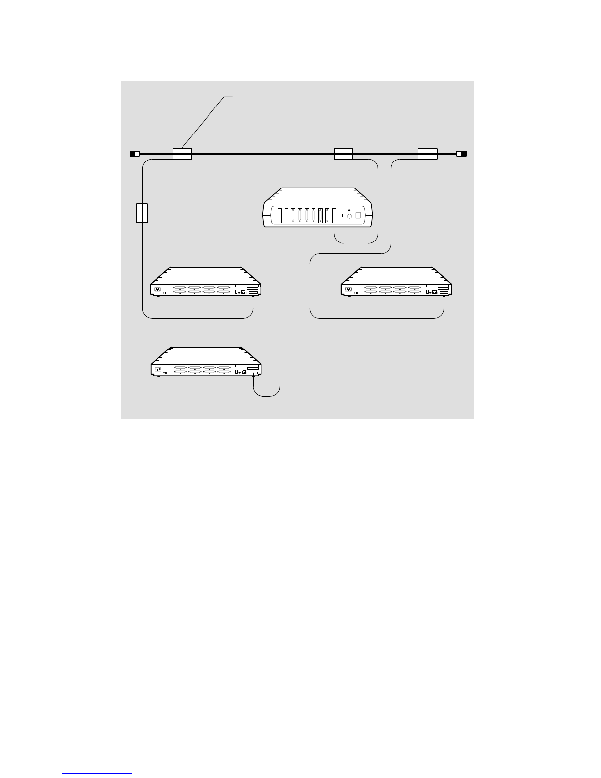
Figure 3–1: Standard Ethernet Coaxial Cable Connection
Transceiver
Standard Ethernet
coaxial cable
Transceiver cable
Etherjack
DECserver 700
DECserver 700
DELNI
DECserver 700
Transceiver cables
LKG-5570-91I
3–3Cabling the Site
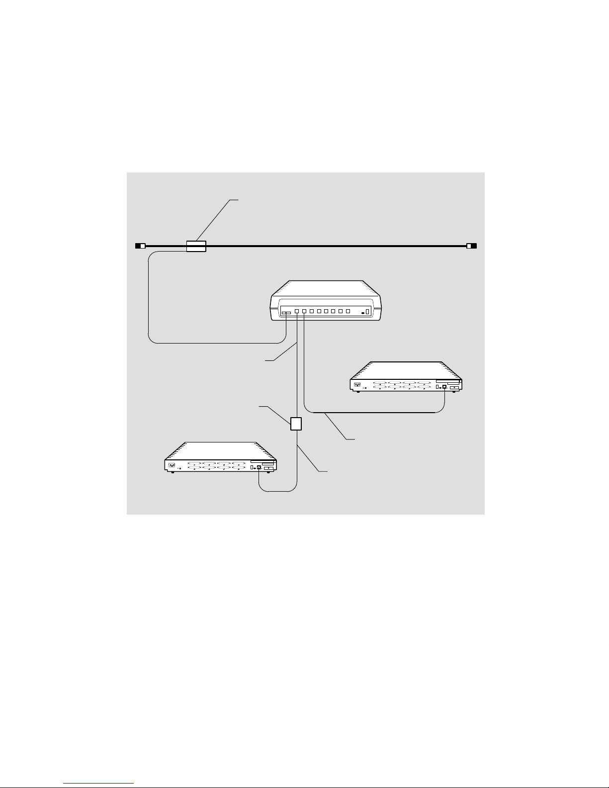
3.2.2 Installing the 10BaseT Ethernet Cables and Devices
You can connect the DECserver 700 to a DETPR (Figure 3–2) by using:
• BN24F cable for local wiring requiring crossover
• BN25G cable for pin-to-pin building wiring
Figure 3–2: 10BaseT Ethernet Connection
Transceiver
Standard Ethernet coaxial cable
DETPR
Transceiver cable
BN25G cable
DECserver 700-08
(Building wiring
pin-to-pin)
Wallplate
DECserver 700-08
BN24F cable
BN24F cable
LKG-5571-91I
3–4 Site Preparation and Maintenance
 Loading...