

Digital Equipment DECserver 300 Hardware Installation

DECserver 300
Hardware Installation
•
Order No. EK-A0366-1N-001
DECserver 300
Hardware Installation
June
1989
This
manual
and
how
DECserver
Is
Intended
to
verHy
300
for
explains
the
how
Its
operation.
hardware controls
hardware
to Install
the
The
and
Installer
DECserver
manual
Indicators.
and
the
also
server
300
system
descrtbes
This
manual
manager.
the
SupersesslonlUpdate
Order Number: EK-A0368-IN-001
Information:
This
Is a new
manual.
EK-A0366-1N-001
June 1989
The information in this document is subject to change without notice and should not
commitment by Digital Equipment Corporation. Digital Equipment Corporation assumes
sibility for any errors that may appear in this document.
Copyright
The following are trademarks of Digital Equipment Corporation:
DEBNA
OEBNET OEUNA
DEC
© 1989 by Digital Equipment Corporation
All Rights Reserved.
Printed in U.S.A.
OESVA
m
••
amu'"
o ECconnect LAN Bridge
DECnet
OECserver
OECUS LN03
DELNI LOP02
OELUA
OELOA Micro/RSX
OEMPR
OEONA
OESOA
LA120
LN01
MASS BUS
MicroVAX
PDP
Professional
be construed as a
Q-Bus
Rainbow
RSX
RSX-11
ThinWire
ULTRIX-32
UNIBUS
VAX
VAXcluster
VAXmate
VAXstation
VMS
M-PLUS
no
respon-
IBM
is a registered trademark of International Business Machines Corporation.
by
This manual was produced
Networks and Communications Publications.
Preface
1 Overview
Contents
1.1 Installation Overview
1.2 Hardware Overview
1.2.1 Models
1.2.2
1.2.3
1.3 Software Requirements
1.4 Service Options
1.4.1 Digital
1.4.2
1.4.3
1. 4.4 Software
1.4.5
2
Unpacking
Features
Server Controls, Indicators.
DECmailer
Installation Service
Training
.................................................
of
On-Site
Product
...............................................
the
Boxes
... ; ....................................
.........................................
the
DECserver
...........................................
Service
..............................................
.......................................
Service Agreements . . . . . . . . . . . . . . . . . . . . . . . .
300
.............................
and
Connectors
.....................................
....................................
..................
1-1
1-4
1-10
1-12
1-12
1-15
1-16
1-16
1-16
1-16
1-16
1-16
2.1
Number
of
Boxes
in
Shipment
................................
2-1
iii
2.2
Contents of DECserver 300 Hardware
3 Site Verification
Shipment
..................
2-1
3.1 Verifying Hardware
3.1.1 Physical Requirements
3.1.2
Environmental Requirements
3.1.3 Electrical Requirements
3.1.4 Leakage
3.1.5 Cabling Requirements
3.1.5.1
3.1.5.2
3.2 Pre installation Checks
3.2.1 Hardware Checks
3.2.2
4
Hardware
Standard
ThinWire
Software Checks
Current
Ethernet
Ethernet
Installation
and
Cable Requirements
.....................................
................................
....................................
..........................................
......................................
Connection
Connection
.......................................
.........................................
..........................................
..............................
.............................
....................
3-1
3-1
3-2
3-3
3-3
3-3
3-4
3-4
3-5
3-5
3-5
4.1 Completing
4.2 Placing
4.2.1 Placing
4.2.2 Rack Mounting
4.3 Verifying
4.4 Testing
the
the
the
the
4.4. 1 Selecting
4.4.2 Connecting
4.4. 3 Connecting Power
iv
the
Server Identification
Server
Server Hardware
Thin
...........................................
Server in
Voltage Select Switch Setting
Wire
the
the
Thin
to
an
Office
Server
Ethernet
Wire T
the
Server
..................................
..................................
-Connector
Card
..............................
................................
............................
.......................
......................
and
Terminators
.........
4-1
4-1
4-2
4-2
·~-6
4-8
4-9
4-9
4-11

4.4.4
Running
the
Self-Test
....................................
4-11
4.5 Selecting
4.6 Connecting
4.7
Connecting
4.8 Connecting
4.9 Initializing
4.10
Verifying
5
What
5.1 Problem Indicators
5.2
5.3
5.4
5.5 Diagnostic Dot Blinking
to
Diagnosing Server Problems
Seven-Segment
Diagnostic Dot Off/Seven-Segment Display Flashing. .
Do
the
Thin
to
to
to
the
the
If
You Have Problems
Wire
or
Standard
Standard
the
a Device Port . . . . . . . . . . . . . . . . . . . . . . . . . . . . . . . . .
Server . . . . . . . . . . . . . . . . . . . . . . . . . . . . . . . . . . . . . . .
Server System Installation
Display Orf
Ethernet
ThinWire
..........................................
Ethernet
..................................
...................................
......................................
Ethernet
LAN
........................
LAN
.......................
LAN
..............
.....................
............
4-15
4-16
4-18
4-20
4-21
4-21
5-1
5-1
5-2
5-3
5-3
5.5.1
5.5.2
5.5.3
5.5.4
5.5.5
5.5.6
5.5.7
5.5.8
5.6
Error
Error
Error Messages 925
Error
Error
Error
Standard
Error
ThinWire
No Messages
Seven-Segment
Messages 920
Messages 922
Messages 930
Messages 935
Messages 941, 942, 950,
Ethernet
Messages 941, 942, 950
Ethernet
on
and
921
................................
and
923
................................
and
926
................................
and
931
................................
and
936
................................
.........................................
........................................
Console Terminal
Display has a
"3"
and
952/Display shows
and
952/Display shows
...........................
.............................
"9"
"9"
5-4
5-4
5-4
5-5
5-5
5-5
5-7
5-8
5-9
v
5.6.1
Down-Line
Load
Starts,
Then
Fails
..........................
5-9
5.6.1.1
5.6.1.2
5.6.2
Error
Message
Error
Message 916
Down-Line
Load
912
................
......................................
Does
Not
Start
...........................
A Connector and Cable Pin Descriptions
A.1
Connector
A.1.1
A.1.2
A.2
A. 2.1
A.2.2
A.3
A.3.1
A.3.2
Ethernet
Port
Cable Structure
DECconnect
BC16E-xx
Cable Adapters, Couplers
H8571-x
H3103
Pin Descriptions
Transceiver Interface
Connector
MMJ
Interface
...
. . . . . . . . . . . . . . . . . . . . . . . . . . . . . . . . . . . . . .
SER Cable
6-Conductor
DEC423 to
Loopback
.................................
.............................
..................................
..................................
DEC Office Cable
and
Loopback
EIA-232-D
Connector
Passive
.........................
,' ~ .. ' .................
...................
Connectors
Adapters
............
............
..
5-9
5-9
5-10
A-1
A-1
A-2
A-3
A-3
A-7
A-7
A-7
A-10
A.3.3
A.3.4
A.3.S
H8572
Loopback
H4080
6-Pin
Turnaround
Cable Coupler
Connector
..............................
(DEC
Connector
12-22196-02)
..................
............................
B Port Devices Supported by the DECserver 300
B. 1
Terminals................................................
B.2 Personal
B.3
vi
Printers..................................................
Computers
. . . . . . . . . . . . . . . . . . . . . . . . . . . . . . . . . . . . . .
A-11
A-11
A-12
..
B-1
B-1
B-2
C Cabling Strategies
.
C.l
Server-to-Network
Connection
C-l
C.l.l
C.1.2
C.2
C.2.1
C.2.2
Standard
ThinWire
Server-to-Device Connection
Connecting to Server Directly
Connecting
Ethernet
Ethernet
to
Patch Panel
D Ordering Information
0.1
DECserver 300 Shipment
0.1.1
0.2
0.3
D.4
D.4
DECserver 300 Country Kits
DECserver 300 Accessories
DEC
OFFICE
Transceiver Cables
ThinWire
Cable (BC16E)
Ethernet
Connection
Connection
........................................
Cables
.............................
.............................
................................
..............................
................................
...............................
.................................
and
Adapters
..................................
...................
C-l
C-3
C-6
C-6
C-8
0-1
0-2
0-4
D-4
D-6
D-7
E How to Order Documents
E.l
Order
E.1.1
E.1.2
E.1.3
E.1.4
E.l.S
E.2
Ordering Procedures for Customers . . . . . . . . . . . . . . . . . . . . . . . . . .
E.3
Ordering Procedures
Numbers
VMS Software Documentation Kits
TSM
Documentation Kit
UL
TRIX-32
User Software Documentation Kit
Hardware Documents
...........................................
Software Documentation Kit
.....................................
For
.........................
...................................
...
...........................
Digital Employees
.....................
. . . . . . . . . . . . . . . .
..
..
E-l
E-l
E-2
E-2
E-2
E-2
E-3
E-4
vii

Eo301
Software
Documentation
Kits 0 0 0 0 0 0 0 0 0 0 0 0 0 0 0 0 0 0 0
00
0 0 0 0 0 0 0 0 0
E-4
Eo302
F
Down-Line
Fol
Figures
Figure
Figure
Figure
Figure
Figure
Figure
Figure
Figure
Hardware
Load
Down-Line
1-1:
DECserver 300 System Installation 0 . 0 0
1-2:
DECserver 300
1-3:
DECserver 300
2-1:
Contents
4-1:
Removing
4-2:
Rack mounting
4-3:
Locating
4-4:
Removing
Manuals
Load
0000000000000000000000000000000000
..... 0 .. 0 .. 0 ...... : ...... 0 ................
Model
Back
of
the
DECserver 300 Hardware
the
covers 0
the
the
Voltage Label 0
the
Voltage Label
DSRVF-Bx
Panel
..... 0 .....
Server
.0
..........
..
0 0
..
0 0 0
0 . 0
.. 0 ...
0 . 0 . 0 .
... ; ......................
..........
...
0 0
..
00' 0 0
Shipment
....
0 0
000
. 0 0 . 0 . 0 0
0 0 . 0 0
.......
0
......
... 0 ... 0 ..
..
.....
... 0 ...
.....
0 0
0 0
...
....
0 0
...
0 0
o.
...
0 .
0 0 0
...
E-4
F-l
1-2
1-11
1-13
2-2
4-5
4-6
4-7
4-7
viii
Figure
Figure
Figure
Figure
Figure
Figure
Figure
Figure
Figure
4-5:
Checking
4-~:
Adjusting
4-7:
Selecting
4-8:
Connecting
4-9:
Connecting Power to
4-10:
4-11:
4-12:
4-13:
The
Seven-Segment
Selecting
Unlocking
Connecting
the
Voltage Select
the
Voltage Select Switch
Thin
Wire
Ethernet
the
ThinWire
the
Display
Standard
the
the
or
Thin
Slide
Latch
Transceiver Cable
Switch.
....
.............
T-Connector
Server
........
......
Wire
..........
Ethernet
0 0
... 0 ...............
0 . 0 . 0 0 . 0
and
Terminators
0 0 0 0
0 0
...
0 0
. 0 0 0 0 . 0 0
0 0 . 0 0 0 0 . 0
... 0 ..
0 . 0 0 0
...
0 . 0 0 0
.....
..
0 0
....
..
0 0 0 0
.. 0 .....
0 0 . 0 . 0
..
...
0 0
0 0
..
.. 0 4-8
4-10
4-11
0 . 0 .
4-12
0 0
..
4-15
.. 0 4-16
0 0 0 .
4-17
4-7
4-9
Figure
4-14:
Locking
the
Standard
Ethernet
Connector
..............
4-17
Figure
Figure
Figure
Figure
Figure
Figure
Figure
Figure
Figure
Figure
Figure
Figure
Figure
4-15:
4-16:
A-1:
A-2:
A-3:
A-4:
A-5:
A-6:
A-7:
A-8:
A-9:
A-10:
A-11:
Connecting
Connecting
Pin Numbers for
Interface
Pin
Number
DECconnect
to
the
Thin
to
a Device Port
Standard
Connector
for Serial Communication
SER Cable - Pin Numbers
DECconnect SER Cable - Wiring
Wiring Diagram for
Wiring Diagram Wiring Diagram Wiring Diagram Wiring Diagram -
H8571-A
H8571-B
H8571-C
H8571-C
Wiring Diagram Wiring Diagram -
Wire
Ethernet
LAN
.........................
Ethernet
Transceiver
.................................
Connector
Diagram.
BC16E-xx
H8571-E
H3103
Cable
Adapter
Adapter
Adapter
Adapter
Adapter
Loopback
..................
..................
...................
...................
...................
.................
Connector
. . . . . . . . . . . . .
........
................
. . . . . . . . . . . .
........
,
..
4-19
4-20
A-2
A-3
A-5
A-6
A-7
A-8
A-8
A-9
A-9
A-10
A-10
Figure
Figure
Figure
Figure
Figure
Figure
Figure
Figure
Figure
Figure
A-12:
A-13:
A-14:
C-1:
C-2:
C-3:
C-4:
C-5:
C-6:
F-l:
Wiring Diagram - H8572
Loopback
H4080
Standard
ThinWire
DEMPR
DEMPR
Connecting
Using
the
Down-Line
Connector
Turnaround
Ethernet
Ethernet
Connector
Coaxial Cable Connection
Stand-Alone
ThinWire Connection
Connections
to
Server Directly
25 Pin D
Load
................................
Adapter
- Server Unable to
6-Pin
(DEC
12-22196-02)
......................
Segment
........................
.........................
..........................
Cable Coupler
............
...............
Locate
Host
.........
...........
........
A-11
A-11
A-13
C-2
C-4
C-5
C-6
C-7
C-8
F-2
ix
Tables
Table
Table
Table
Table
Table
Table
Table'
Table
Table
Table
Table
Table
Table
1-1
1-2
1-3
3-1:
3-2:
3-3:
3-4:
3-5:
3~aximum
/
4-1:
4-2:
5-1:
A-1:
Server Controls
Server Indicators
Server Connectors
Physical Specification of
Environmental Specifications
Electrical Requirements
Leakage
Maximum Cabling Distances
Seven
Diagnostic
Display/Indications
Pin Descriptions for
....................................
..................................
.................................
the
Server
......................
of
the
Server
...............................
Current
.....................................
............................
Cabling Distances - Server to Devices
-Segment
Display Codes
Dot
Display
........................
...............................
...................................
Standard
Ethernet
...............
..........
1-14
1-14
1-14
3-2
3-2
3-3
3-3
3-4
3-4
4-14
4-14
5-2
x
Table
Table
Table
Table
Table
Table
Table
Table
Table
Transceiver Interface
A-2
D-1:
D-2:
D-3:
D-4:
D-5:
E-1:
E-2:
E-3:
Pin Descriptions for Serial Communication
DECserver 300
DECserver 300 Country Kits
DECserver 300 Accessories
DEC
OFFICE
ThinWire Cable
Hardware
How to
How to
Cable
Documents
Order
Order
by
by Mail
.................................
Order
Codes
.........................
.........................
...........................
and
Adapters
and
Connector
Order
................................
Phone
..............................
...............................
Interface
.....................
Codes
............
....
A-2
A-3
D-l
D-3
D-4
D-<i
D-7
E-3
E-3
E-3
Intended Audience
The
DECserver 300 Hardware Installation/Owner's Guide
hardware installer.
installed
verify the system installation.
and
The
tested.
The
The
DECserver 300 system
DECserver
300 software.
installer
person installing the DECserver 300 software can
300 hardware unit
Structure of This Document
The
DECserver 300 Hardware Installation/Owner's Guide contains the following
chapters
Chapter
and
appendixes:
1
Provides
an
overview of the system installation.
Preface
is
intended for the
is
responsible for ensuring that the hardware
NOTE
is
comprised of a
and
DECserver
is
then
Chapter
Chapter
Chapter
Chapter
2
3
4
5
Describes how to unpack
ment.
Describes how to verify that the site
and
lists the technical specifications of the server.
Provides instructions for installing
ware.
Provides simple troubleshooting steps to correct problems
countered
during the hardware installation.
and
check
and
the contents of the ship-
is
prepared for installation
testing the server
hard-
en-
xi
Appendix
A
Describes
also describes various cables,
with
the
connector
server.
pins for
the
various
adapters
server
and
accessories
connectors
used
and
Appendix
Appendix
Appendix
Appendix
B
Lists
C
Describes
vices.
D
Provides
and
Describes how to
E
the
port
devices which
procedures
information
server cables.
Other DECserver 300 Manuals
• Using
•
intended
manager.
the
Outlines
information
remaining
ferent
300
the
audiences.
Documentation
DECsener
Provides
node
the
address,
for the
DECsener
DECserver 300 system,
for using,
documentation
3017
space
and
300
Introduction
expanding
and
This
document
Set.
Identification Card
to
record
DECnet
network
manager,
are
supported
to
cable
to
the
on
ordering
order
Documents.
hardware
or
reconfiguring
flowcharts logical reading
is
intended
the
serial
number,
node
name
the
software installer,
of
the
the
and
for any user
Ethernet
server. This
by
the
network
server,
software,
the
and
server
and
server. Describes
sequences
of
the
Address,
document
and
server.
to
port
accessories
provides
for dif-
DECserver
DECnet
is
the
server
de-
the
• DECserl'er
• DECserver
xii
300
Software Installation
Explains how to install
establish
tem
ing system. This guide
the
Describes
guide provides
mands.
to
down-line
installation.
server
manager.
300
the
This
DECserver
load hosts,
In
the
Use
user
interface
complete
guide
is
300 ports. .
(op-sys)
the
DECserver
and
title,
(op-sys)
is
intended
and
information for using all nonprivileged
intended
for
300 dist.ribution software, how to
how to verify
is
the
for
the
load
the
general functions
user's
of
the
DECserver
name
of
·the
host
system
of
interactive terminals
load
manager
the
server.
300
host
operat-
and
This
server
connected
sys-
com-
• Terminal Server User's Reference Card
Descrihes
server
interactive terminals
• DECserver
Describes all
DECserver 300 manager.
configure the ports
bases
• Terminal
Describes the usage
erence
server. This reference
and
commands
300
the
of
the
server. This guide
Sener
also lists
gives examples
on
a reference card. This
connected
Management
initial
and
day-to-day
The
and
to customize the
Commands
and
syntax
and
describes all status
is
intended
of
the most frequently used nonpriviJeged
card
is
intended for users
to server ports.
management. tasks required to the
topics cover all the information
permanent
is
intended
and
Messages Reference
of
all terminal server commands. This
to the DECserver 300 manager.
and
error
and operational
messages issued
for the server manager
terminal users who want more detailed reference information.
• DECserver
Describes hardware logic, software
intended
level
Ethernet
PDP-1I
300
Technical Description
and
diagnostic firmware. This manual
for use in training, in field service,
of
technical information assumes previous training
networks
and
with Digital Equipment Corporation's
and
architecture.
in
manufacturing.
needed
by
but
is
useful for
or
experience with
VAX-II
of
to
data-
ref~
the
is
The
or
• Local Area Transport (LA
Describes
concepts. This
manager,
• Terminal
Defines terms used in
the
Local Area Transport (LAT) protocol,
document
and
the network manager.
Sener
Glossary
the
reference tool for all users
T)
Network Concepts
is
intended
server
of
server documentation.
for the server manager, the system
documentation
and
sets. This
LAT
is
intended
network
as a
xiii
DECserver 300 On-Line Documentation
• DECserver
Describes any discrepancies between
tion in
installer
•
On-Line
Provides two forms of server help: t.utorial help
help. Tutorial help provides basic information
the server.
using all
tended
300
Release Notes
the
documentation
and
the
DECserver 300 manager.
Help
Command
the
server
for all server users.
reference help provides detailed information
commands
Associated Documents
• Guide to Terminal Server Manager
Installation Guide
These
Terminal Server l\1anager (TSM) software,
ment
net-VAX.
Digital Equipment Corporation
installer
documents
product,
These
and
manager
contain the information necessary to install
which
is
guides describe how to use
of
set.
installed
the
TSM
the
actual
These
available at your privilege level. Help
notes
and
Terminal Server Manager Software
onto a VAX/VMS
Ethernet
terminal servers
software
product
are
intended
and
command
about
logging in
an
optional network
system running DEC-
TSM
to manage a mix
product.
and
the
for
the
reference
and
and
connected
informasoftware
run
manage-
using
about
is
in-
the
of
for
the
xiv
1.1
Installation Overview
1
Overview
Installing
• Installing
• Installing
• Verifying
This
DECserver 300 hardware.
ing
tion manual.
There
hardware
installed
hardware
Figure
the
DECserver 300 system consists of:
the
the
the
chapter
the
system installation
is
1-'
provides
Connection
in detail.
Appendix C and
ning
no
prescribed
is
installed
on a load
and
software must
1 identifies
hardware
software
system installation
and
order
and
host
the
an
overview
The
procedure
are
contained
to
individual devices
Further
Configuration Guide.
for, installing
tested
before
or
both
major
of
the
for installing
in
the
NOTE
information
in
the
DECconnet
without using
after
the
be
installed
steps
that
make
system installation
the
DECserver
is
not
described
is
can
be
found in
System Plan-
the
hardware
the
software.
hardware
to
verify
up
is
the
total system installation.
and
of
software
300
and
installed. However,
the
and
for verify-
Software Installa-
the
software.
The
software
system installation.
can
the
The
be
the
1-1
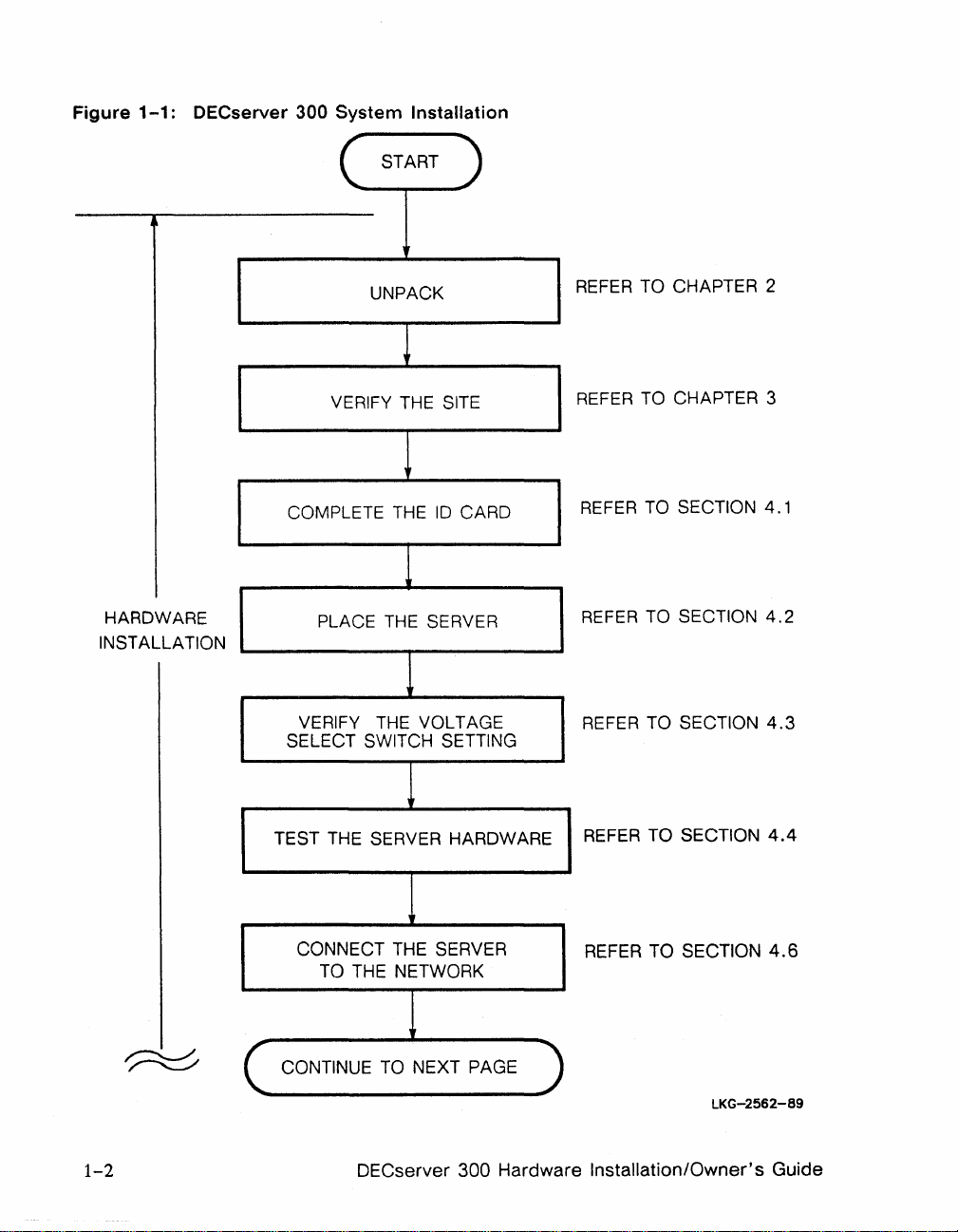
Figure
1-1:
DECserver 300
System
START
Installation
HARDWARE
INSTALLATION
UNPACK
VERIFY THE SITE
COMPLETE THE
PLACE
VERIFY THE VOL T AGE
SELECT SWITCH SETTING
TEST THE SERVER HARDWARE
THE
10
CARD
SERVER
REFER TO CHAPTER 2
REFER TO CHAPTER 3
REFER TO SECTION
REFER TO SECTION
REFER TO SECTION
REFER TO SECTION
4.1
4.2
4.3
4.4
1-2
CONNECT THE SERVER
TO THE NETWORK
CONTINUE TO NEXT PAGE
DECserver 300 Hardware Installation/Owner's Guide
REFER TO SECTION
LKG-2562-89
4.6
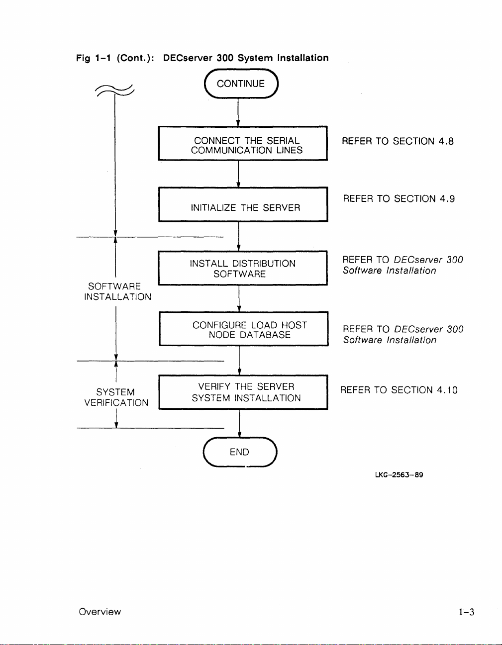
Fig
1-1
(Cont.):
OECserver 300
CONTINUE
System
Installation
t
SOFTWARE
INST ALLATION
I
i
SYSTEM
VERIFICATION
~
CONNECT THE SERIAL
COMMUNICATION LINES
INITIALIZE THE SERVER
INSTALL DISTRIBUTION
SOFTWARE
CONFIGURE LOAD HOST
NODE DATABASE
1
VERIFY THE SERVER
SYSTEM INSTALLATION
REFER TO SECTION
REFER TO SECTION
REFER TO DECserver 300
Software Installation
REFER TO DECserver 300
Software Installation
REFER TO SECTION
4.8
4.9
4.10
Overview
END
LJ<G-2563-89
1-3
1.2 Hardware Overview
The
DECserver
printers
etc.)
300
is
an
to
communicate
Ethernet
on
terminal
an
Ethernet
WARNING
server
LAN.
that
allows devices (terminals,
Ethernet
meters
equipment.
pearing
the
system as
clauses
to
potential
repeaters
ures
Digital
Ethernet-installationer
tusindvis
separate
i
installationerne
del
publikation
413.1.
udenfor
skal
for galvanisk is6lering
oplysninger henvises til
ing.
installations may
and
on
the
equipment
defined
413.1. 2 and
couple
af
equipment
bonded
or
must
be
Equipment
af
dele
et
flIes
6.
Hvor
det
der
anvendes
couple
other
strre
hundreds
To
prevent
installation, it
be
part
in
lEe
413.1.
area
such
employed.
Corporation
ADVARSEL
meter
364-4-41,
og forbinde
af
udstyr.
er
det
jordingspunkt
det
er
ndvendigt
flIes
jordingspunkt
optisk kobling eller
extend
hazardous
of a common
publications
6.
outside
via
Ethernet,
galvanically
If
in
kan
For
vigtigt,
klausulerne
af
udstyret.
den
to
of
separate
is
important
\Vhere
of
the
doubt
for advice.
strkke
hundredevis
at
undg
at
som
defineret i lEe
at
lokale
thousands
items
voltages ap-
that
equipotential
364-4-41
it
is
required
main
then
optical
isolated
please
farlig
alt
forbinde
via
For
Digital afdel-
meas-
refer
sig
spnding
udstyret
413.1.2
udstyr
Ethernet,
anden
yderligere
of
of
all
equi-
to
over
af
er
og
form
1-4
DECserver
300 Hardware Installation/Owner's Guide
VAROITUS
Ethernet-verkot
ja niihin voidaan
verkkoon
kaikkien laitteiden
samaan
ominaisuudet
364-4-41.
Ethernetiin
potentiaalintasausjrjesteImn,
voivat oIla tuhansia metrej pitki
Hitt
satoja erilaisia laitteita. Jotta
ei psisi syntymn vaarallisia jnnitteit,
on
ehdottomasti kuuluttava
potentiaaHntasausjrjestelmn,
on
kohdissa
halutaan
mritetty
413.1.2
liitt laite,
IEC:n
ja
413.1.6.
joka
on
kytettv optisia
jonka
julkaisussa
Mikli
ei kuulu
toistimia tai vastaavia galvaanisesti eristettyj
menetelmi. Jos et ole varma kytettvst menetelmst,
ota yhteys Digitaliin.
DANGER
Une
installation
kilomtres
d'viter
d'une
dfinie
tout
mise la
par
413.1.6).
net
des quipements
et
S'il
Ethernet
relier des centaines
peut
s'tendre
d'lments.
problme lectrique, vrifiez
terre
I'IEe
s'avre
commune
(364.4.41,
ncessaire
non
rattachs
ainsi qu'eUe est
clauses
de
relier
une
sur
Ia
prsence
413.1.2
par
Ether-
mme
terre,
des
Afin
et
utilisez des "rpteurs optiques ou autres matriels of-
frant la
prenez
mme
qualit d'isolation.
contact
avec Ies Services
En
cas
de
techniques
doute,
Digi-
tal.
Overview
VORSICHT
Ethernet-Netzwerke
tausend
einzelne
Meter
Gerte
meidung von gefhrlichen
Netzwerk ist es unbedingt erforderlich,
Gerte
sind, wie
Abschnitte
Wenn
Ethernet
Teil
einer
in
413.1. 2 und
Gerte
auerhalb
miteinander
den
mssen optische Repeater
knnen
erstrecken
miteinander
sich
und
mehrere
verbinden.
ber
mehrere
hundert
Zur
Spannungen
gemeinsamen Erdungsschleife
IEC-Richtlinien
413.1.
der
Erdungsschleife
verbunden
oder
andere
364-4-41,
6 angegeben.
werden
galvanisch
da
mssen,
getrennte Mittel verwendet werden. Falls
Fragen
haben.
wenden
Sie sich
an
Digital Equip-
ment.
Ver-
im
aIle
ber
Sie
1-5
WAARSCHUWING
Ethernet-configuraties
verschillende kilometers overbruggen
den
afzonderlijke
den.
Om
te
vermijden
spanningen
is
het
maakt
zouden
belangrijk
van dezelfde voeding
zoals gedefinieerd
364-4-41,
neer
bepalingen
apparatuur
die niet op eenzelfde equipoten-
tiaal spanningsnet
gekoppeld
maken
moet
van optische repeaters of van
vanisch isolerende
u contact op te
nemen
Ethernettinstallasjoner
tusen
meter
og ha tilkoblet flere
lige utstyrsenheter.
pst farlige spenninger p installasjonen,
kunnen
apparaten
dat
voordoen
dat
aIle
in
413.1.2.
is
aangesloten via
worden,
moet
technieken.
met
ADVARSEL
kan
strekke seg over flere
For
forhindre at
een
afstand van
en
met
elkaar verbin-
er
zich gevaarlijke
op
de
configuratie,
apparatuur
en
dezelfde
de
IEC-publikatie
en
413.1.6. Wan-
men
andere
Bij
twijfel gelieve
Digital.
hundre
det
honder-
gebruik
aarde,
Ethernet
gebruik
gal-
forskjel-
skal op-
er
det
viktig at alt utstyret tilhrer et felles ekvipotensialt
forbindelsessystem, slik
publikasjon
413.1.6.
Ethernet
hovedomrdet,
364-4-41,
Der
hvor
utenfor
er
det
det
er
definert i
paragrafene 413.1.2
det
er
pkrevet koble utstyr via
det
pbudt
benytte optiske lin-
IEC-
og
ekvipotensiale
jeforsterkere (repeatere) eller tilsvarende galvanisk isolert materiale. Kontakt Digital hvis
i tvil.
du
er
1-6
DECserver 300 Hardware Installation/Owner's Guide
ATTENZIONE
Le installazioni Ethernet possono estendersi
per
migliaia di metri e collegare diverse centinaia di
elementi separati di apparecchiature.
il
rischio di scariche elettriche al momento dell'in-
stallazione, importante che tutte
ad
un
ture siano colle gate
comune sistema di
Per evitare
Ie
apparecchia-
massa come definito nella pubblicazione IEC
364-4-41,
si
richieda di collegare l'apparecchiatura fuori
dalla principale area di massa via Ethernet,
claus ole 413.1.2 e 413.1.6. Laddove
si
devono utilizzare ripetitori su fibra ottica 0 qualsiasi altro strumento isolato gslvanicamente.
Per
qualsiasi informazione rivolgersi alla sede Digital
pi vicina.
AVISO
A instalao da Ethernet
de
hares
metros e agrupar centenas
pode
estender-se
de
por
itens
mil-
de
equipamento.
Para evitar que voltagens perigosas surjam na in-
stalao, importante que todo
de
parte
urn sistema elctrico equipotencial
comum, tal como definido na publicao
0 equipamento faa
364-4-41
do IEC, clusulas 413.1.2 e 413.1.6.
Overview
Onde fr necessrio ligar equipamento fora
de
principal
ligao elctrica equipotencial, atravs
da
rea
da
Ethernet, devero ser empregues repetidores
ou
pticos
Em caso
outras solues galvanicamente isoladas.
de
dvida, contacte a Digital.
1-7
PRECAUCIN
Las instalaciones
hasta cientos
equipos. Para evitar tensiones peligrosas
de
Ethernet
de
metros y a
pueden
un
gran
extenderse
nmero
en
de
la instalacin, es importante que todos los equipos formen
parte
de
un
sistema equipotencial comn, tal y
en
como se define
364-4-41,
clusulas 413.1.2 y 413.1.6.
sea necesario conectar equipos a trays
net
fuera del
rea
las publicaciones del IEC
de
equipotencial principal,
Cuando
Ether-
deben
emplearse repetidores pticos u otros elementos
En
aislados galvnicamente del mismo tipo.
de
duda, Ie rogamos se ponga
en
contacto
caso
con
Digital Equipment Corporation.
VARNING
Ethernet
och
undvika spnningsfara, r
installationer
kan
vara tusentals
koppla ihop hundratals enstaka delar.
det
viktigt att alla delar
meter
Fr
att
ingr i ett ekvipotentiellt system enligt definitionen
i IEC publikationen
1. 2 och
413.
kopplas via
413.1. 6. D
Ethernet
364-4-41,
utanfr
det
krvs att utrustning
det
ekvipocentiellasys-
temet, mste optiska frstrkare eller
klausulerna
annan
galvaniserad isolering anvndas. Vid eventuella
oklarheter,
kontakta
Digital Equipment AB fr
rdgivning.
1n1
,D~'UD
D~nnD
'l~~n
1
O~9'
nN
.Dnwn~
D~'nH
u1fD~
~J. ~~9pn~
~
1
n'lno.'l
'l~
~~1Jn
D~l~~n
D~U~DN~
1-8
~9~N
~~J
~lWn
nflD
,IEC
nf~D~
ln1N~
'~11nw
-l
~lnD
~TN
1N
.~l,pn
~'g
~U
D~DU9~
.D~~,gf
~l~~
~ND
,1pnD~
nN~Dfn
~gJ
.413.1.6
~l~~
,ETHERNET
~U~,g
nlU~DN~
(OPTICAL
~U~l~~
~'WD~ nlfg~
DECserver 300 Hardware Installation/Owner's Guide
nlu,nWD
~U~,g
nfJo
ngnlWD
,~N~~fU19~1
1~~
n1ND
nl1n~
~DWn
-1
413.1.2
'~n~
,ngnlWDn
REPEATERS,
Nt
ETHERNET-n
nDJ
nJ~DD
nJ~
w,~
n~WN'n
BRIDGES)
.~nJnD
,nlpgO
n1fpn,
~l~J~
D~~l~UW D~~~DWn
D~11Wn
D~!PUO
Dn~w
~U91N
~,
l"lun~l
n1~1~U
p~n
nl1n~
,n~~~J'D
364-(-41
n1D1pD3
~D.~'
nJ~D
~l~~l
D~~~1l~'
n~~Dl
-1
--It
·t
..
,'/
t··
Cl)
3~
iW
'.f
~ T ~ -.~
--=-
19"
Cf)
iii
iW
1:"
9 (fA
The
DECserver 300 hardware supports
dard.
EIA-423-A
cabling runs
age
to
computing equipment caused by electrical overstress (EOS)
discharges
equipment
(ESD). EOS
failure.
is
compatible with
and
higher signalling speeds.
and
ESD are
~if)
the
the
EIA-232-D
In
addition,
the
most
t::
&.
EIA-423-A
common
t::
&
~
to:::
y~~
=-
c
t;~~)
electrical interface stan-
interface
EIA-423-A
causes
t)
but
supports longer
minimizes dam-
and
electrostatic
of
communications
t)
"
Jt T
,;.
The
DECserver 300 system allows any combination
computer
nected
supports 16 asynchronous serial
Wire
Overview
to
and
systems
the
computer
standard
on a LAN
Ethernet
via
systems
interfaces.
the
port
device connectors.
and
to
their
resources.
data
communication channels
of
16
attached
The
devices access
Each
device is con-
DECserver 300 system
and
has
both
to
Thin-
1-9
The
DECserver 300 system supports devices
eration. It has two additional signals, DSR
that
require
and
DTR, which may
data-leads-only
be
used as follows:
for op-
• DSR logout - Logs out
an
attached device
on
power-down
• DSRlDTR - Flow control for printers or other attached devices
• DSR - Status signal check for printers
NOTE
The
DECserver 300 does not support connections
via
to wide-area networks
tions to
non-LAT
hosts. Users requiring these ca-
modems,
or
connec-
pabilities should use the DECserver 200/MC
which provides asynchronous modem support
and
uses
1.2.1
Models
There
is
only one model of the DECserver 300 (DSRVF-Bx) but this model has
two versions depending
Model
Version
(both dial-in and dial-out) ,
EIA-232-D
interface.
on
the input voltage as shown below .
Input
Voltage
DSRVF-BA 100-120 Vac
DSRVF-BB
220-240
Vac
the
1-10
The
server
is
shown in Figure
1-2.
DECserver 300 Hardware Installation/Owner's Guide
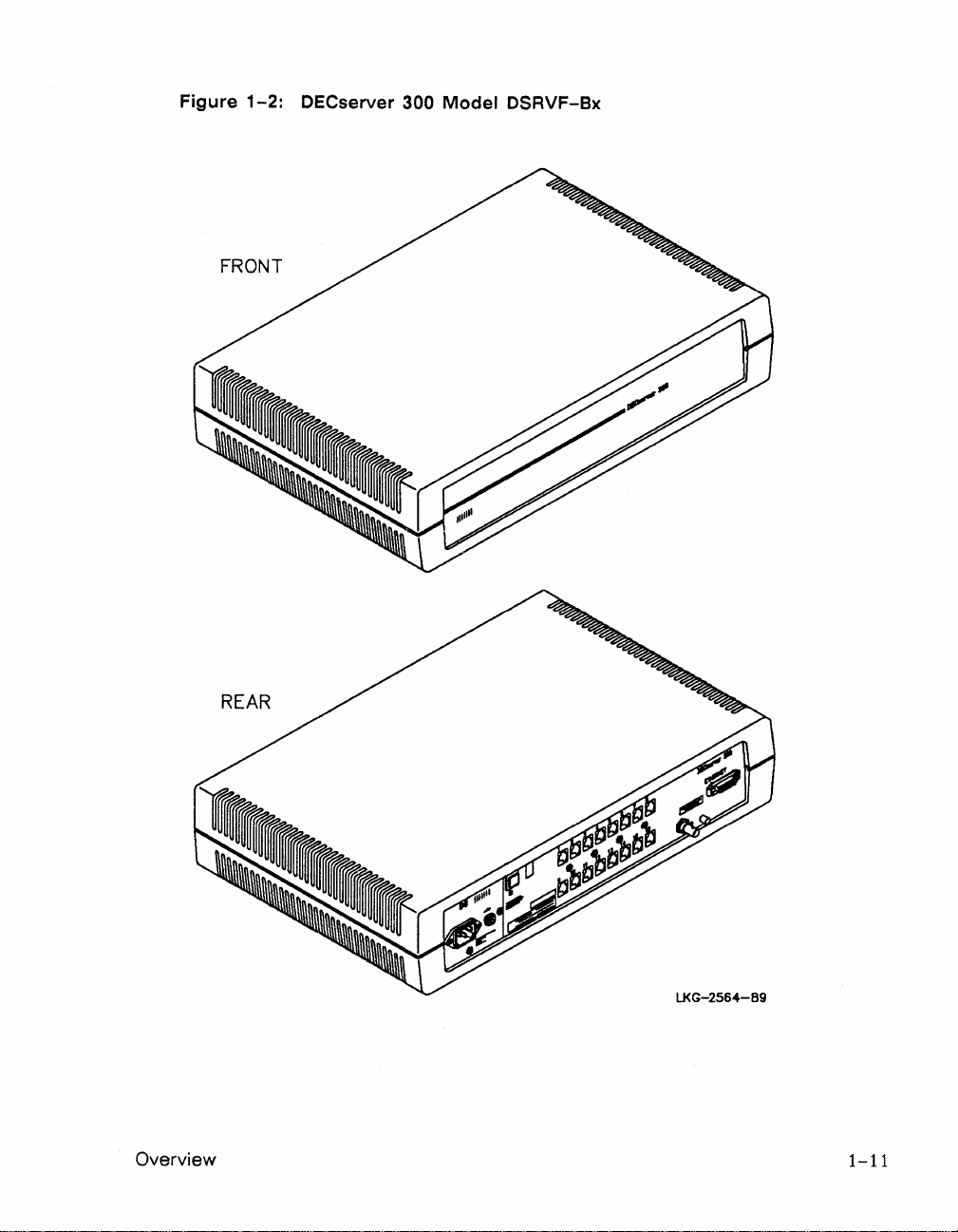
Figure
FRONT
1-2.
. OECserver 3
00 Model 0
RVF-8x
S
Overview
REAR
LKG-2564-B9
1-11
1.2.2
Features of the DECserver 300
The
DECserver 300 system offers
the
following features:
• Permits fast, easy connections between
ports
and
the
devices
• Manages device traffic
on
and
the
tions tasks
• Reduces
and
simplifies cabling required for connecting devices to a net-
work
• Provides access
Area
cal
1.2.3
Server
All
of
Controls~
the
operation are located
The
server controls are described in Table
Table
1-2
(Further
and
Appendix
information
Transport
server controls, indicators,
and
to
Digital Equipment Corporation host systems
(LA
T) network
Indicators, and Connectors
on
the
rear
a brief description
on
the
connectors
A.).
the
devices
network
allows computer systems
and
of
of
the
the
connectors
server
1-1.
connectors
and
associated cables
that
and
are
The
indicators are described in
is
attached
more
are
used during server
shown
g~ven
in Table
is
to
the
server
time for applica-
on
the
Lo-
in
Figure
given in
1-3.
1-3.
Chapter
4
1-12
DECserver 300 Hardware Installation/Owner's Guide
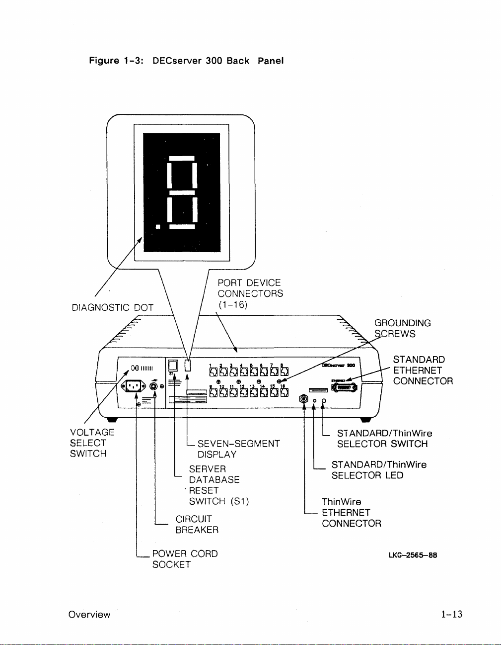
Figure
1-3:
DECserver 300
Back
PORT
CONNECTORS
(1-16)
Panel
DEVICE
GROUNDING
SCREWS
VOLTAGE
SELECT
SWITCH
Overview
_POWER
SOCKET
SEVEN-SEGMENT
DISPLAY
SERVER
DATABASE
"RESET
SWITCH (S1)
CIRCUIT
BREAKER
CORD
SI
ANDARD/ThinWire
SELECTOR SWITCH
ANDARD/ThinWire
ST
SELECTOR LED
ThinWire
ETHERNET
CONNECTOR
LKG-2565-88
STANDARD
ETHERNET
CONNECTOR
1-13
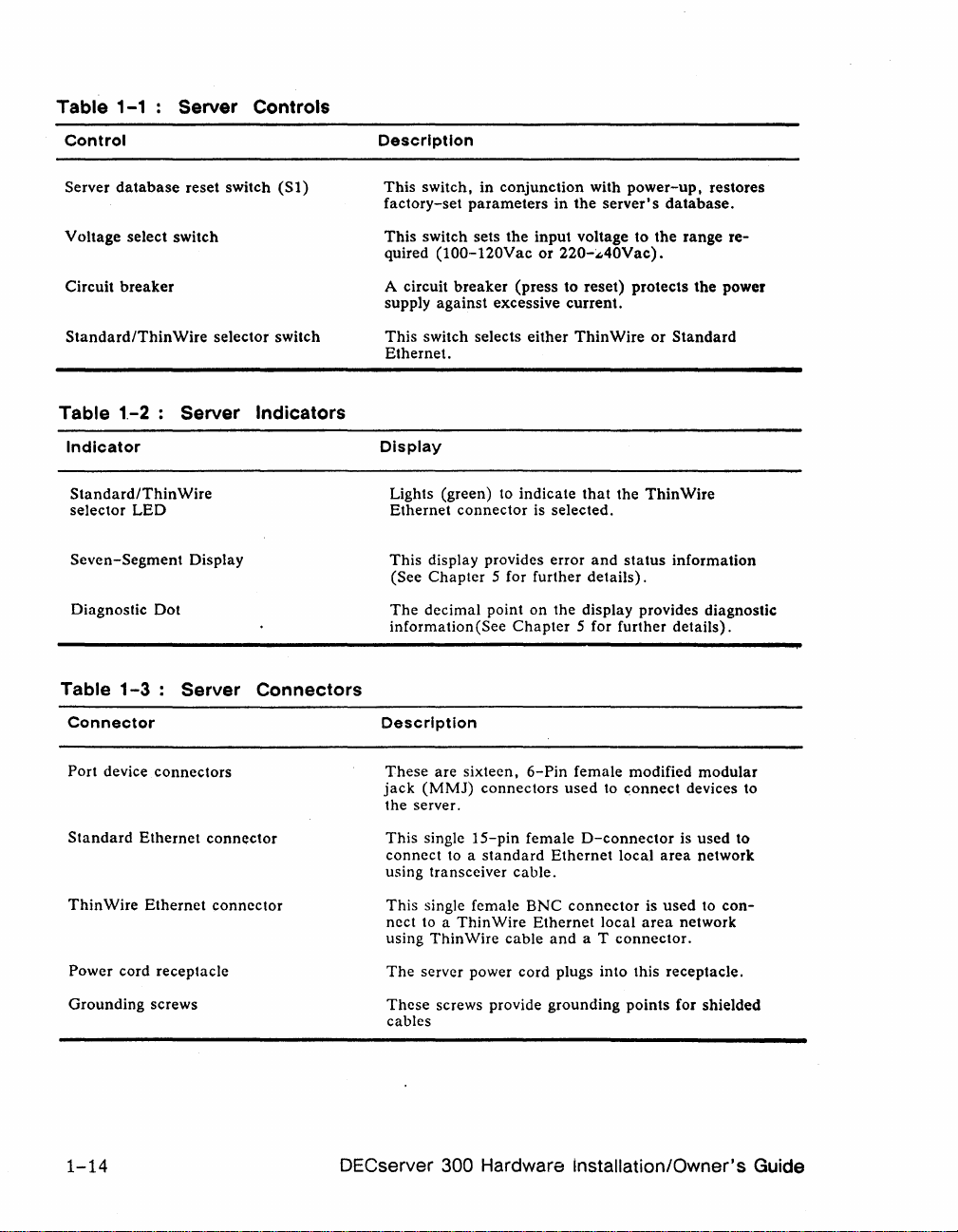
Table
1-1 Server Controls
Control
Server
database
Voltage select switch
breaker
Circuit
Standard/Thin
Table
Table
1.-2 Server
Indicator
Standard/Thin
selector
Seven-Segment
Diagnostic
1-3:
Connector
reset switch
Wire
Wire
LED
Display
Dot
Server
(St)
selector switch
Indicators
Connectors
Description
This
switch,
factory-set
This
quired
A circuit
supply
This
Ethernet.
Display
Lights (green) to
Ethernet
This
(See
The
information(See
Description
parameters
switch sets
(t
OO-t20Vac
breaker
against
switch selects
connector
display provides error
Chapter
decimal point
in
conjunction
the
input
or
(press
excessive
either
indicate
is selected.
S for further
on
Chapter
with
in
220-~40Vac).
to reset)
current.
the display provides diagnostic
power-up,
the
server's
voltage to
protects
ThinWire
that
the
ThinWire
and
status
details).
S for further
or
restores
database.
the
range
the
Standard
information
details).
re-
power
Port device
Standard
Thin
Power cord
Grounding screws
Wire
connectors
Ethernet
Ethernet
receptacle
1-14
connector
connector
These
are sixteen,
jack
(MMJ)
the server.
This
single
connect
using transceiver
This
nect to a
using
The
These
cables
to a
single female
Thin
ThinWire
server power cord plugs into this
screws provide grounding
6-Pin
connectors
IS-pin
female
standard
cable.
ENC
Wire
cable
female modified
used
O-connector
Ethernet
connector
Ethernet
and
a T
is
area
is
used
area
network
receptacle.
(or shielded
modular
used
to
network
to
con-
to <;onnect devices to
local
local
connector.
points
DECserver 300 Hardware installation/Owner's Guide
1.3 Software Requirements
The
software requirements for installing
follows:
and
operating
the
DECserver 300
are
as
• DECserver 300 distribution software - Installed
system load host.
•
DECnet
load
•
LA
municate
You must install
software.
loaded
ever
required,
image, running
the
server to
tecture
The
service
each
service
ating systems:
• VMS operating systems
•
ULTRIX-32
Phase
IV
software - Installed
host
(not
required
T service
The
to a DECserver 300.
on
node
software
with DECserver 300s
the
distribution software
distribution software includes a server image file
and
provides
on
the
DECserver 300, constitutes
perform
the
node
node.
its functions.
DECserver 300.
software supports
The
LA
operating system
for
UL
TRIX systems).
-:-
Installed
and
The
load host
the
server image to any
The
server software implements
the
LA
T software
is
on
each
on
all
LA
their devices.
on
a load host
down-line
number
the
T architecture
packaged with
on
each
DECserver 300
DECserver 300 system
T service
that
loads
server software
and
each
nodes
runs
DECnet
that
the
server image when-
of
servers.
must
of
the
that
is
down-line
The
that
the
LA
be
installed
following oper-
Phase
enables
T archi-
com-
IV
server
on
All software must
For
more
information, see
applies to
Overview 1-15
each
be
installed
specific operating system.
and
the
DECserver
verified before you
can
operate
300
Software Product Description
the
server.
that
 Loading...