


DECrepeater 90FS
Installation and Configuration
Part Number: EK–DEFMI–IN. A01
August 1994
This manual describes how to install and configure the
DECrepeater 90FS module.
Revision/Update Information: This is a new manual.

Copyright
August 1994
The information in this document is subject to change without notice and should not be construed as a
commitment by Digital Equipment Corporation. Digital Equipment Corporation assumes no responsibility for any
errors that may appear in this document.
Copyright 1994 by Digital Equipment Corporation.
All rights reserved. Printed in U.S.A.
The postage-paid Reader’s Comments form at the back of this document requests your evaluation of this
document to assist us in preparing future documentation.
The following are trademarks of Digital Equipment Corporation: DEC, DECconnect, DEChub, DEChub ONE,
DECndu, DECndu Plus, DECrepeater, Digital, HUBwatch, MultiSwitch, OpenVMS, ThinWire, ULTRIX, VAX,
VMS, and the DIGITAL logo.
MS-DOS is a registered trademark of Microsoft Corporation.
ST is a registered trademark of American Telephone and T elegraph Company.
FCC NOTICE — Class A Computing Device:
This equipment generates, uses, and may emit radio frequency energy. The equipment has been type tested and
found to comply with the limits for a Class A computing device pursuant to Subpart J of Part 15 of FCC Rules,
which are designed to provide reasonable protection against such radio frequency interference when operated in
a commercial environment. Operation of this equipment in a residential area may cause interference; in which
case, measures taken to correct the interference are at the user’s expense.
VCCI NOTICE — Class 1 Computing Device:
This equipment is in the 1st Class category (information equipment to be used in commercial and/or industrial
areas) and conforms to the standards set by the Voluntary Control Council for Interference by Data Processing
Equipment and Electronic Office Machines aimed at preventing radio interference in commercial and/or industrial
areas. Consequently, when used in a residential area or in an adjacent area thereto, radio interference may be
caused to radios and TV receivers.
Read the instructions for correct handling.
CE NOTICE – Class A Computing Device:
Warning!
This is a Class A product. In a domestic environment this product may cause radio interference, in which case the
user may be required to take adequate measures.
Achtung!
Dieses ist ein Gerät der Funkstörgrenzwertklasse A. In Wohnbereichen können bei Betrieb dieses Gerätes
Rundfunkstörungen auftreten, in welchen Fällen der Benutzer für entsprechende Gegenmaßnahmen
verantwortlich ist.
Attention!
Ceci est un produit de Classe A. Dans un environment domestique, ce produit risque de créer des interférences
radioélectriques, il appartiendra alors à l’utilisateur de prendre les mesures spécifiques appropriées.

iii
Contents
Safety
Introduction 1. . . . . . . . . . . . . . . . . . . . . . . . . . . . . . . . . . . . . . . . . . . . . . . . . .
Features 2. . . . . . . . . . . . . . . . . . . . . . . . . . . . . . . . . . . . . . . . . . . . . . . . . . .
Front Panel 3. . . . . . . . . . . . . . . . . . . . . . . . . . . . . . . . . . . . . . . . . . . . . . . . . .
Back Panel 4. . . . . . . . . . . . . . . . . . . . . . . . . . . . . . . . . . . . . . . . . . . . . . . . . . .
Installing the Module 5. . . . . . . . . . . . . . . . . . . . . . . . . . . . . . . . . . . . . . . . .
Installing the Module as a Standalone Unit 5. . . . . . . . . . . . . . . . . . . . . . . .
Removing the Back Cover 8. . . . . . . . . . . . . . . . . . . . . . . . . . . . . . . . . . . . .
Installing the Module into a DEChub 900 9. . . . . . . . . . . . . . . . . . . . . . . . .
Installing the Module into a DEChub 90 11. . . . . . . . . . . . . . . . . . . . . . . . . .
Connecting the Cables 13. . . . . . . . . . . . . . . . . . . . . . . . . . . . . . . . . . . . . . . .
Removing the Module 16. . . . . . . . . . . . . . . . . . . . . . . . . . . . . . . . . . . . . . . .
Configuring the Module 18. . . . . . . . . . . . . . . . . . . . . . . . . . . . . . . . . . . . . .
Setup Port Description 18. . . . . . . . . . . . . . . . . . . . . . . . . . . . . . . . . . . . . . .
Setup Port Device Cabling 18. . . . . . . . . . . . . . . . . . . . . . . . . . . . . . . . . . . .
Accessing the Setup Port 19. . . . . . . . . . . . . . . . . . . . . . . . . . . . . . . . . . . . . .
Start Redirect Mode 21. . . . . . . . . . . . . . . . . . . . . . . . . . . . . . . . . . . . . . . . .
DECrepeater 90FS Installation Menu (DEChub 90/Standalone Options) 22
DECrepeater 90FS Installation Menu (DEChub 900 Options) 23. . . . . . . . .
Description of Menu Options 24. . . . . . . . . . . . . . . . . . . . . . . . . . . . . . . . . .
LED Descriptions 47. . . . . . . . . . . . . . . . . . . . . . . . . . . . . . . . . . . . . . . . . . . .
Problem Solving Using the LEDs 48. . . . . . . . . . . . . . . . . . . . . . . . . . . .
Normal Powerup 48. . . . . . . . . . . . . . . . . . . . . . . . . . . . . . . . . . . . . . . . . . . .
Connector Pin Assignments 51. . . . . . . . . . . . . . . . . . . . . . . . . . . . . . . . .
AUI (15-pin D-Sub) Connector 51. . . . . . . . . . . . . . . . . . . . . . . . . . . . . . . . .
Serial Port (8-pin MJ) Connector 51. . . . . . . . . . . . . . . . . . . . . . . . . . . . . . . .
H8571-J Adapter 52. . . . . . . . . . . . . . . . . . . . . . . . . . . . . . . . . . . . . . . . . . . .
H8575-A Adapter 52. . . . . . . . . . . . . . . . . . . . . . . . . . . . . . . . . . . . . . . . . . . .

iv
Contents (Cont.)
H8585-AC Adapter 53. . . . . . . . . . . . . . . . . . . . . . . . . . . . . . . . . . . . . . . . . .
H8584-AA Adapter 53. . . . . . . . . . . . . . . . . . . . . . . . . . . . . . . . . . . . . . . . . .
H8585-AA Adapter 54. . . . . . . . . . . . . . . . . . . . . . . . . . . . . . . . . . . . . . . . . .
Redundant Fiber-Optic Link Configuration 55. . . . . . . . . . . . . . . . . .
Redundant Fiber-Optic Link Overview 55. . . . . . . . . . . . . . . . . . . . . . . . . . .
Redundant Fiber-Optic Link Components 55. . . . . . . . . . . . . . . . . . . . . . . . .
Redundant Fiber-Optic Link Operation 57. . . . . . . . . . . . . . . . . . . . . . . . . .
Simple Redundant Link Configuration 58. . . . . . . . . . . . . . . . . . . . . . . . . . .
Complex Redundant Link Configuration 59. . . . . . . . . . . . . . . . . . . . . . . . .
Partial Fault Detection 60. . . . . . . . . . . . . . . . . . . . . . . . . . . . . . . . . . . . . .
Full Fault Detection 61. . . . . . . . . . . . . . . . . . . . . . . . . . . . . . . . . . . . . . . .
Recommendations for Redundant-Link Configuration 62. . . . . . . . . . . . . . .
Fiber-Optic Loss Budget 63. . . . . . . . . . . . . . . . . . . . . . . . . . . . . . . . . . . . .
10BaseFL Loss Budget 63. . . . . . . . . . . . . . . . . . . . . . . . . . . . . . . . . . . . . . .
FOIRL Compatibility 64. . . . . . . . . . . . . . . . . . . . . . . . . . . . . . . . . . . . . . . . .
Product Specifications 66. . . . . . . . . . . . . . . . . . . . . . . . . . . . . . . . . . . . . . .
Associated Documents 68. . . . . . . . . . . . . . . . . . . . . . . . . . . . . . . . . . . . . .
Tables
1 DLU Process Description 35. . . . . . . . . . . . . . . . . . . . . . . . . . . . . . . . . . . .
2 Module LED States 47. . . . . . . . . . . . . . . . . . . . . . . . . . . . . . . . . . . . . . . .
3 Problem Solving Using the LEDs 48. . . . . . . . . . . . . . . . . . . . . . . . . . . . .
4 Partial Fault Detection Versus Full Fault Detection 62. . . . . . . . . . . . . . .
5 10BaseFL Worst-Case Loss Budget 63. . . . . . . . . . . . . . . . . . . . . . . . . . .
6 FOIRL Worst-Case Loss Budget 64. . . . . . . . . . . . . . . . . . . . . . . . . . . . .
7 DECrepeater 90FS Best-Case Maximum Launch Power 65. . . . . . . . . . .
8 Operating Specifications 66. . . . . . . . . . . . . . . . . . . . . . . . . . . . . . . . . . . .
9 Acoustical Specifications 67. . . . . . . . . . . . . . . . . . . . . . . . . . . . . . . . . . .

v
Safety
!
Any warning or caution that appears in this manual is defined as follows:
WARNING Contains information to prevent personal injury.
CAUTION Contains information to prevent damage to equipment.
VORSICHT Enthält Informationen, die beachtet werden müssen, um
den Benutzer vor Schaden zu bewahren.
ACHTUNG Enthält Informationen, die beachtet werden müssen, um
die Geräte vor Schaden zu bewahren.
DANGER Signale les informations destinées à prévenir les acci-
dents corporels.
ATTENTION Signale les informations destinées à prévenir la détério-
ration du matériel.
AVISO Contiene información para evitar daños personales.
PRECAUCION
Contiene información para evitar daños al equipo.

vi
Safety
!
(Cont.)
The cautions that must be observed for the hardware described in this manual are
listed below in English, German, French, and Spanish. The pages on which these
safety messages appear are also listed.
WARNING
!
Some fiber optic equipment can emit laser or infrared light that
can injure your eyes. Never look into an optical fiber or connector port. Always assume the cable is connected to a light
source. [Pages 14 and 16.]
VORSICHT Bestimmte Lichtleitergeräte können für die Augen
gefährliches Laser– oder Infrarotlicht abstrahlen. Vermeiden
Sie es daher unter allen Umständen, direkt in ein Lichtleiterkabel oder einen Lichtleiteranschluß zu schauen. Gehen
Sie immer davon aus, daß Lichtleiterkabel mit einer Lichtquelle verbunden sind.
DANGER Certains équipements à fibre optique peuvent émettre un
rayonnement laser ou infra–rouge pouvant provoquer des
troubles oculaires. Ne regardez jamais à l’intérieur d’une
fibre optique ou d’un port de connecteur. Considérez que le
câble est connecté en permanence à une source lumineuse.
AVISO Ciertos equipos de fibras ópticas pueden emitir luz lasérica
o infrarroja con riesgos de lesiones en los ojos. No se debe
nunca mirar en una fibra óptica o una puerta de conexión.
Siempre hay que suponer que el cable está conectado a
una fuente luminosa.

vii
Safety
!
(Cont.)
CAUTION
!
This action deletes all configured settings and replaces
them with factory default values. All configuration settings
will be lost. [Page 25.]
ACHTUNG Bei diesem Vorgang werden alle Konfigurationseinstel-
lungen gelöscht und die Werkseinstellungen wieder eingesetzt. Alle Konfigurationsdaten gehen verloren.
ATTENTION Cette action supprime tous les paramètres de configura-
tion et les remplace par des valeurs prédéfinies. Tous
les paramètres de configuration seront perdus.
PRECAUCION
Esta intervención borrará todos los parámetros de configuración y los sustituirá por valores por defecto definidos
de fábrica. Se perderán todos los parámetros de configuración.

viii
Safety
!
(Cont.)
CAUTION
!
If power is interrupted during Stage 3 of the DLU process,
the firmware image can become corrupted. Do not turn off
power to the unit or perform any action that can cause the
unit to lose power during Stage 3 of the DLU process.
[Pages 34, 36, and 39.]
ACHTUNG Sollte während der Phase 3 des DLU–Prozesses eine
Unterbrechung der Stromversorgung eintreten, kann das
Firmwareprogramm zerstört werden. Aus diesem Grunde
wird dringend empfohlen, Vorkehrungen zu treffen, daß
während der Durchführung dieser Phase 3 die Systemeinheit weder ausgeschaltet noch die Stromversorgung
unterbrochen werden kann.
ATTENTION L’image du microprogramme risque d’être corrompue, en
cas de coupure de courant au cours de l’étape 3 du processus DLU. Ne mettez pas l’unité hors tension et n’exécutez aucune action risquant d’entraîner une coupure
d’alimentation au cours de cette étape.
PRECAUCION
Si se interrumpe el suministro eléctrico durante la Etapa
3 del proceso DLU, puede dañarse la imagen del firmware. No se debe apagar la unidad ni realizar ninguna
operación que pueda causar una interrupción del suministro de la unidad durante la Etapa 3 del mencionado
proceso.

1DECrepeater 90FS Installation and Configuration
Introduction
The DECrepeater 90FS (also referred to in this manual as the module) is an Ethernet
repeater that provides two external 10BaseFL fiber-optic ports and one external AUI
port.
In this manual, the term 10BaseFL refers to the International Standards Organization
(ISO) 8802-3/ANSI/IEEE 802.3 fiber-optic local area networks (LAN) standards.
In this manual, the term Ethernet is Digital’s term for its product compatibility with the
ISO 8802-3/ANSI/IEEE 802.3 standards and the Ethernet standards for Carrier
Sense Multiple Access with Collision Detection (CSMA/CD) LANs.
To give your workgroup LAN media flexibility and connectivity, the module can be
configured into a DEChub 900 MultiSwitch (also referred to in this manual as the
DEChub 900), into a DEChub 90, or as a standalone unit. One or more (up to eight)
can be installed into a DEChub 900.
When installing the module into a DEChub 900 or in a DEChub 90, the module’s
hot-swap capability allows you to install or remove the module without turning off
power.
The module provides a side panel ThinWire port connector, used when the module is
installed as a standalone unit. The module provides a ThinWire port connection to
the backplane when the module is installed in a DEChub 900 or a DEChub 90.
The module’s front panel provides two fiber-optic ports that can operate
independently or as a redundant pair, and one attachment unit interface (AUI) port.
The front panel also provides light-emitting-diodes (LEDs) that indicate the status of
the module, the ports, and the network.
The module includes a serial port on the front panel that can be used as an
installation setup port when the module is installed into a DEChub 90 or installed as a
standalone unit. Using the setup menu, you can enable the module’s front panel
serial port for Out-of-Band Management (OBM).
NOTE: When the module is installed in a DEChub 900, you
must use the Hub Manager setup port on the DEChub
900 instead of the module’s setup port.

2
DECrepeater 90FS Installation and Configuration
Introduction (Cont.)
Features
Your DECrepeater 90FS module includes the following features:
• ThinWire, 10Base2 port available as an external connection on the module side
panel (when the module is installed as a standalone unit) or to the backplane
segment in a DEChub 900 or a DEChub 90.
• Backplane access to another Ethernet LAN through a single flexible channel in a
DEChub 900.
• Automatic module self-test at powerup.
• Port-level packet address security.
• In-band Simple Network Management Protocol (SNMP) management.
• OBM using SNMP over Serial Line Internet Protocol (SLIP) provides an addi-
tional path to the normal in-band management as follows:
– Through the OBM connector on the DEChub 900 Hub Manager
– Through the front-panel serial port on the module when the module is
installed into a DEChub 90 as a standalone unit.
• Built-in SNMP agent supports the following management information bases
(MIBs):
– Ethernet-like Interface Type MIB (RFC 1398)
– Internet Engineering Task Force (IETF) Repeater MIB (1516)
– Digital Extended Repeater MIB
– DEChub 900 Public Common MIB
– MIB II (RFC 1213)
• Manageability using any generic SNMP management application that supports
the MIBs listed above.
• Upgradeable device firmware (in nonvolatile Flash memory) using Trivial File
Transfer Protocol (TFTP) with Digital’s Network Device Upgrade (DECndu) Plus
utility or through the setup port with any TFTP server.
• User-friendly advanced Graphical User Interface (GUI) manageability with
Digital’s HUBwatch Network Management Station (NMS) application.

3DECrepeater 90FS Installation and Configuration
Front Panel
1) Power
LED — Lights when the module has
5 volts of power.
2) Module OK
LED — Lights when the the
module passes self-test.
3) Network Activity
LED — Indicates
network traffic level.
4) Network OK
LED — Indicates the status
of either the side panel or backplane
ThinWire, 10Base2 port.
5) Redundancy Enabled
LED — Lights when the
fiber-optic ports are operating as a redundant pair.
6) Port State LEDs — The LEDs (labeled 1 through
3) show the attachment status of the associated port
to a LAN.
7) Port Link LEDs — Light when fiber-optic cables of
the associated port are properly connected to a
functional remote fiber-optic device.
NOTE: Refer to the section titled LED
Descriptions for more information
about LED operation.
8) Ethernet address label — Shows the Ethernet
address of the module.
9) Fiber-optic TX
port ST-type connectors —
Connect fiber-optic cables to the receive ports of the
remote fiber-optic device.
10) Fiber-optic RX
port ST-type connectors —
Connect fiber-optic cables to the transmit ports of
the remote fiber-optic device.
11) Ethernet AUI (15-pin D-Sub) port connector —
connects to an external medium attachment unit
(MAU) directly or by using an AUI cable.
12) Serial port (8-pin MJ) connector — Multiplexed
port can be used as a setup port or for OBM.
13) Cooling fan unit — Provides air circulation.
14) ThinWire port connector — Connects through a
BNC T-connector when module is operating as a
standalone unit.
LKG-8817-93I
Side view
2
3
9
9
10
10
11
7
7
13
12
6
1
4
5
8
14

4
DECrepeater 90FS Installation and Configuration
Back Panel
1) Locking tab — Locks the module into a
DEChub 900 or DEChub 90 backplane.
2) 48-pin connector — Provides network and
power connections to the module when the
module is installed into a DEChub 900 or a
DEChub 90.
3) Grounding bolt — Provides a chassis
grounding connection to the module when
the module is installed into a DEChub 900 or
a DEChub 90.
4) Power connector — Receives dc current
from the power supply. This feature is used
for standalone operation only.
5) Manufacturing label — Lists the module
part number, serial number, revision level,
and power requirements.
6) Mounting tab — Secures the module to the
backplane when the module is installed into a
DEChub 900 or a DEChub 90.
7) Cooling fan unit — Provides air circulation.
8) Back cover — The back cover is used only
when the module is a standalone unit.
LKG-8881-93I
2
4
5
6
1
3
8
7

5DECrepeater 90FS Installation and Configuration
Installing the Module
You can install the DECrepeater 90FS as a standalone unit, or you can install the
module into a DEChub 900 MultiSwitch or DEChub 90. For installation instructions,
refer to the following table.
If...
And... Then...
You are installing the
module as a
standalone unit.
Go to the section titled
Installing the Module as a
Standalone Unit.
You are installing the
module into a
DEChub 900 or a
DEChub 90.
Your module has a
back cover.
Go to the section titled
Removing the Back Cover.
You are installing the
module into a
DEChub 900.
Your module does not
have a back cover.
Go to the section titled
Installing the Module into a
DEChub 900.
You are installing the
module into a
DEChub 90.
Your module does not
have a back cover.
Go to the section titled
Installing the Module into a
DEChub 90.
Installing the Module as a Standalone Unit
You can use the DECrepeater 90FS as a standalone unit by placing it onto a table,
mounting it onto a wall, or installing it into a standard 19-inch rack using a shelf
assembly (Digital Part Number: H9544–MS).

6 DECrepeater 90FS Installation and Configuration
Installing the Module
Installing the Module as a Standalone Unit
NOTE: Install the module horizontally to ensure that the fans
have at least 2 inches of clearance.
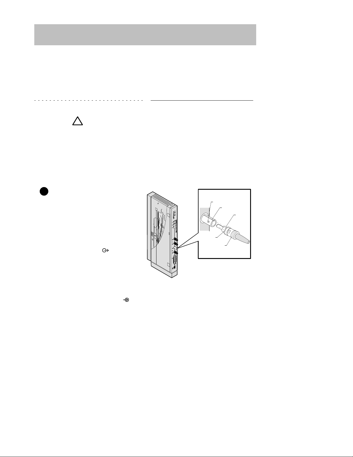
1 Connect the ThinWire
T-connector:
a. Attach the ThinWire T-connec-
tor to the BNC connector and
turn the connector one-quarter
turn to the right until the connector locks into place.
b. Attach the ThinWire backbone
segment to one of the BNC connectors on the T-connector.
c. Install a terminator on the other
end of the T–connector, or connect a ThinWire cable to another 10Base2 device.
NOTE: To disconnect the ThinWire
T-connector, turn the connector
one-quarter turn to the left until
the connector clears the BNC
connector stem, then disconnect
the cable.
2 Connect the power cable.
a. Connect the cable from the
power supply (Digital Part Number: H7827-BA) to the power
connector on the back of the
module.
b. Plug the power supply cable
into the power supply, then into
a wall outlet.
LKG-9174-93I

7DECrepeater 90FS Installation and Configuration
Installing the Module (Cont.)
Installing the Module as a Standalone Unit (Cont.)
3 Verify that the module’s Power
LED lights immediately and
that the Module OK
LED lights
within 1 minute.
a. The Power
LED lights when
power is applied, then the module performs a self-test.
b. After the module completes the
self-test, the Module OK
LED lights and remains lit.
NOTE: If the LEDs do not operate as described, refer to the
section titled Problem Solving Using the LEDs.
Go to the section titled Connecting the Cables.
LKG–8820-93I

8 DECrepeater 90FS Installation and Configuration
Installing the Module (Cont.)
Removing the Back Cover
Remove the back cover if you are installing a module into a DEChub 900 or into a
DEChub 90.
1 Lift up the latch on the back cover
by inserting a flat-blade screwdriver into the top mounting hole.
2 With the latch up, pull the top of
the back cover away, pivoting at
the bottom of the module.
3 To install the module:
• Into a DEChub 900, go to the
section titled Installing the Module
into a DEChub 900.
• Into a DEChub 90, go to the
section titled Installing the Module
into a DEChub 90.
LKG-8818-93I

9DECrepeater 90FS Installation and Configuration
Installing the Module (Cont.)
Installing the Module into a DEChub 900
The DECrepeater 90FS hot-swap feature allows you to install the module into the
DEChub 900 without turning off power. Seating the module initiates the powerup
sequence.
1 Compare your module’s power
requirements with the values
shown in the Hub Manager status
display (see examples).
NOTE: The 12-volt power in the DEChub 900 is derived from the
15-volt power source.
2 Seat the module into the
DEChub 900.
a. Place the module’s mounting
tab into a mounting slot on the
DEChub 900.
b. Pivot the module on the
mounting tab and align the
connectors.
c. Firmly push the module onto the
backplane connectors until the
release lever clicks.
d. Press down on the release lever
to ensure that it is locked.
Module’s Manufacturing
Label (Example)
If any of the module’s power requirements
exceed the values shown in the status display, add another power supply (see the
DEChub 900 MultiSwitch Owner’s Manual).
Hub Manager Status
Display (Example)
LKG–9540–94I
Available: 90.5 W
5V: 13.0 A, 15V: 3.5 A
PN
A01
AS41601069
C–208/90
REV
SN
FTZ
–DEFMI–M
5Vdc,1.5; 12Vdc, .5A, 15W
LKG–8727-93I
Mounting
tab
Release lever clicks
when module is
seated.

10 DECrepeater 90FS Installation and Configuration
Installing the Module (Cont.)
Installing the Module into a DEChub 900 (Cont.)
3 Verify that the module’s Power
LED lights immediately and
Module OK
LED lights within
1 minute.
a. The Power LED lights when
power is applied, then the module performs a self-test.
b. After the module completes
self-test, the Module OK
LED lights and remains lit, then
the Hub Manager status display
shows:
DECrepeater 90FS
up.
NOTE: If the LEDs do not operate as described, refer to the
section titled Problem Solving Using the LEDs.
Go to the section titled Connecting the Cables.
LKG–9550-94I

11DECrepeater 90FS Installation and Configuration
Installing the Module (Cont.)
Installing the Module into a DEChub 90
The DECrepeater 90FS hot-swap feature allows you to install the module into the
DEChub 90 without turning off power. Seating the module initiates the powerup
sequence. Install the module into slot 7 or 8 only.
NOTE: Ensure that the fans have at least 2 inches of
clearance.
1 Install the module into the
DEChub 90.
a. Place the module’s mounting
tab into slot 7 or 8 only on the
DEChub 90. Only slots 7 and 8
provide the 12 volts required by
the DECrepeater 90FS.
b. Pivot the module on the mount-
ing tab and align the connectors.
c. Firmly push the module onto the
backplane connectors until the
release lever clicks.
d. Press down on the release lever
to ensure that it is locked.
LKG–8837-93I
Mounting
tab
Release lever clicks
when module is
seated.

12 DECrepeater 90FS Installation and Configuration
Installing the Module (Cont.)
Installing the Module into a DEChub 90 (Cont.)
2 Verify that the module’s Power
LED lights immediately and
that the Module OK
LED lights
within 1 minute.
a. The Power LED lights when
power is applied, then the module performs a self-test.
b. After the module completes
self-test, the Module OK
LED lights and remains lit.
NOTE: If the LEDs do not operate as described, refer to the
section titled Problem Solving Using the LEDs.
Go to the section titled Connecting the Cables.
LKG–9550-94I

13DECrepeater 90FS Installation and Configuration
Installing the Module (Cont.)
Connecting the Cables
1 Determine the fiber-optic port configuration
Before connecting the fiber-optic cables, determine whether the ports are to be
configured as redundant pairs or as separate independent ports. The default
configuration is separate independent ports.
Refer to the section titled Redundant Fiber-Optic Link Configuration for more
information. (Refer also to HUBwatch Online Help.)
If you are configuring the fiber-optic ports as:
• Redundant pairs, go to step 2.
• Separate independent ports, go to step 3.
2 Connect the fiber-optic cables for redundancy
NOTE: You must configure the ports using HUBwatch before
connecting the cables. Failure to do so can create a LAN
loop which could bring down that segment of the
network.
a. Select the module and ports to use as the master and the modules and ports
to use as the responders or non-responders.
b. Using HUBwatch, assign the master ports and the responder ports.
c. Following the procedure in step 3, connect the master’s primary port cables
to the master’s primary port.
d. Connect the other end of those cables to the remote primary port.
e. Connect the master’s secondary port cables to the master’s secondary port.
f. Connect the other end of those cables to the remote secondary port.
14 DECrepeater 90FS Installation and Configuration
Installing the Module (Cont.)
Connecting the Cables (Cont.)
If your site is prewired, the fiber-optic cables should be labeled with information
on size and attenuation characteristics. Digital recommends that you use
62.5/125-micron multimode graded index fiber-optic cable with the
DECrepeater 90FS. Refer to the section titled Fiber-Optic Loss Budget for more
information.
WARNING
!
Some fiber-optic equipment can
emit laser or infrared light that can
injure your eyes. Never look into an
optical-fiber or connector port.
Always assume the cable is
connected to a light source.
NOTE: To prevent cable damage, avoid making sharp bends
and kinks in the cable.
3 Connect the fiber-optic cables.
a. Remove the dust caps from the
ST-type connectors on the ports
that you are connecting.
b. Align the tab and slot of the
transmit cable plug with the slot
and tab of the transmit port connector (labeled
).
c. Insert the plug, then push the
plug sleeve in and turn it to the
right, locking it in place.
d. Connect the receive cable, in
the same way, to the receive
port connector (labeled
).
NOTE: To disconnect the cables, push the plug’s sleeve in and
turn it to the left, then disconnect the cable.
Slot
Tab
Slot
Tab
Sleeve
LKG–8836-93I

15DECrepeater 90FS Installation and Configuration
Installing the Module (Cont.)
Connecting the Cables (Cont.)
4 Connect the AUI cable.
a. Push the module’s AUI con-
nector slide latch to the unlocked position.
b. Insert the AUI cable plug into
the AUI connector.
c. Push the module’s AUI con-
nector slide latch to the locked
position.
NOTE: To disconnect the cable, push the connector slide latch
to the unlocked position, then disconnect the cable.
After all cables are installed, go to the section titled Configuring the Module.
LKG–8819-93I
Unlock
Lock

16 DECrepeater 90FS Installation and Configuration
Removing the Module
WARNING
!
Some fiber-optic equipment can emit laser or infrared light
that can injure your eyes. Never look into an optical-fiber or
connector port. Always assume the cable is connected to a
light source.
1 Disconnect the cables from the
module.
a. To disconnect the fiber-optic
cables, push the plug’s sleeve
in and turn it to the left, then
disconnect the cable.
b. To disconnect the AUI connec-
tor, push the connector slide
latch to the unlocked position,
then disconnect the cable.
LKG–8822-93I
Unlock
Tab
Slot
Tab
Sleeve
Slot

17DECrepeater 90FS Installation and Configuration
Removing the Module (Cont.)
2 Unseat the module from the
DEChub900 or the DEChub 90.
a. Lift the release lever located on
the top of the DEChub 900 slot
or the DEChub 90 slot.
b. Pivot the module back on its
bottom mounting tab, and disengage the module from the
backplane.
LKG–8731-93I
Mounting
tab
Lift release lever
LKG–8838-93I
Mounting
tab
Lift release lever

18 DECrepeater 90FS Installation and Configuration
Configuring the Module
Setup Port Description
The setup port on the DEChub 900 MultiSwitch or on the module’s front-panel serial
port (when the module is operating as a standalone unit or in a DEChub 90) allows
you to access and set DECrepeater 90FS parameters. This section describes how to
access the module from either port and set those parameters.
NOTE: The setup port screen displays illustrated in this manual
may vary slightly from the actual screen displays on your
setup port device.
The signals from the DEChub 900 Hub Manager setup port and from the
DECrepeater 90FS front-panel serial port conform to the EIA-232D signaling
standard at 9600 baud. To the user , the port appears as a data terminal equipment
(DTE) device.
NOTE: Devices that use the EIA-423 signaling standard are
compatible with the DEChub 900 Hub Manager setup
port and the DECrepeater 90FS front-panel serial port.
Setup Port Device Cabling
The front-panel serial port on the module or the Hub Manager setup port on the
DEChub 900 can be connected to a setup port device (a terminal or personal
computer), using the following cables and adapters (not included in the shipping kit).
Cable/Adapter Type
Connecting Setup Port Device
BN24H-xx
1
A terminal with a 6-pin MMJ connector
BN24H-xx1/H8575-A A terminal with a 25-pin D-Sub connector
BN24H-xx1/H8571-J
A PC with a 9-pin D-Sub communications port
1
xx indicates cable length in meters.

DECrepeater 90FS Installation and Configuration 19
Configuring the Module (Cont.)
Accessing the Setup Port
To use one of the ports to configure the module, do the following:
1. Ensure that the transmit and receive baud rates on the setup port device are
set to 9600 baud.
2. Connect the setup port device as follows:
a. If you are installing the module into a DEChub 900, connect the setup port
device cable to the setup port on the DEChub 900 (see illustration).
b. If you are installing the module into a DEChub 90 or as a standalone unit,
connect the setup port device cable to the front-panel serial port on the
module (see illustration).
Setup
port
DECrepeater 90FS
front-panel
serial port
DEChub 900 MultiSwitch
H8571-J
H8575-A
To setup port
device
BN24H
cable
H8571-J
H8575-A
To setup port
device
LKG-8825-94I
BN24H
cable
3. Press
Return
on the setup port device a few times until a menu appears.

Choose option 13, then
go to the section titled
Start Redirect Mode.
The DECrepeater 90FS does not
support Option [9] Downline
Upgrade from this menu.
You must choose Option [13]
Start Redirect Mode to perform
a downline upgrade to this module.
20 DECrepeater 90FS Installation and Configuration
Configuring the Module (Cont.)
a. If the setup port device is connected to the module’s front-panel serial
port, the DECrepeater 90FS INSTALLATION MENU appears. Go
to the section titled DECrepeater 90FS Installation Menu
(DEChub90/Standalone Options).
b. If the setup port device is connected to the Hub Manager setup port on the
DEChub 900, the DEChub 900 MultiSwitch INSTALLATION
MENU appears (see following example).
The following is an example of the DEChub 900 MultiSwitch INSTALLATION
MENU:
DEChub 900 MultiSwitch
DEChub 900 MultiSwitch INSTALLATION MENU
[1] Reset with Factory Defaults
[2] Reset with Current Settings
[3] Show Current Settings
[4] Set SNMP Read/Write Community
[5] Add SNMP Trap Addresses
[6] Delete SNMP Trap Addresses
[7] Dump Error Log
[8] Set In-Band Interface IP Address
[9] Downline Upgrade
[10] Set Out-of-Band Interface IP Address
[11] Set Out-of-Band Interface Port Speed
[12] Start Event Display Mode
[13] Start Redirect Mode
Enter selection : 13
Return
c. Choose option 13, then go to the section titled Start Redirect Mode.

Enter the number
of the slot where
the module is
installed.
DECrepeater 90FS Installation and Configuration 21
Configuring the Module (Cont.)
Start Redirect Mode
The Start Redirect Mode option redirects the DEChub 900 Hub Manager setup
port to the setup port of any network module that supports this function (such as the
DECrepeater 90FS) that is installed in the DEChub 900. Choosing this option allows
you to configure or obtain status of an installed network module by accessing the
module’s installation menu.
After you choose the Start Redirect Mode option from the Hub Manager
Installation menu, the screen prompts you for a slot number, as shown in the
following code example.
The following example shows how to select a slot number (user response is shown in
boldface type):
Enter selection: 13
Enter the slot number for redirection: (1–8): 3
Return
Setup port redirected to 3: DECrepeater 90FS
Attempting to connect ...
Connection successful!
After you press
Return
, the DECrepeater 90FS INSTALLATION MENU appears
on your screen. Go to the section titled DECrepeater 90FS Installation Menu
(DEChub 900 Options).

Choose an option,
then go to the section
titled Description of
Menu Options.
If you need to assign
an IP address to the
module, choose this
option.
22 DECrepeater 90FS Installation and Configuration
Configuring the Module (Cont.)
DECrepeater 90FS Installation Menu (DEChub 90/Standalone
Options)
This section lists the options available from the DECrepeater 90FS
INSTALLATION MENU when the module is installed into a DEChub 90 or as a
standalone unit.
The following is an example of the DECrepeater 90FS INSTALLATION MENU:
DECrepeater 90FS
DECrepeater 90FS INSTALLATION MENU
[1] Reset with Factory Defaults
[2] Reset with Current Settings
[3] Show Current Settings
[4] Set SNMP Read/Write Community
[5] Add SNMP Trap Addresses
[6] Delete SNMP Trap Addresses
[7] Dump Error Log
[8] Set In-Band Interface IP Address
[9] Set In-Band Interface Default Gateway Address
[10] Downline Upgrade
[11] Set Out-of-Band Management (OBM)Interface IP Address
[12] Set Out-of-Band Management (OBM) Port Speed
[13] Module-Specific Options
Enter selection : 1
Return

Choose an option,
then go to the section
titled Description of
Menu Options.
If you need to assign
an IP address to the
module, choose this
option.
Indicates the DEChub
slot number where the
module is installed.
DECrepeater 90FS Installation and Configuration 23
Configuring the Module (Cont.)
DECrepeater 90FS Installation Menu (DEChub 900 Options)
This section shows the options available from the DECrepeater 90FS
Installation Menu when the module is installed into the DEChub 900.
The following is an example of the DECrepeater 90FS Installation Menu:
DECrepeater 90FS – Slot 3
DECrepeater 90FS INSTALLATION MENU
[1] Reset with Factory Default
[2] Reset with Current Settings
[3] Show Current Settings
[4] Set SNMP Read/Write Community
[5] Add SNMP Trap Addresses
[6] Delete SNMP Trap Addresses
[7] Dump Error Log
[8] Set In-Band Interface IP Address
[9] Set In-Band Interface Default Gateway Address
[10] Downline Upgrade
[Ctrl/C] Return to DEChub 900 MultiSwitch INSTALLATION MENU
Enter selection : 1
Return

24 DECrepeater 90FS Installation and Configuration
Configuring the Module (Cont.)
Description of Menu Options
This section describes the menu options that are available from the DECrepeater
90FS Installation Menu. Note that the out-of-band management options
apply to the module only when it is installed into a DEChub 90 or it is in standalone
mode.
[1] Reset with Factory Defaults
This option resets the module, causing most of the module’s configured NVRAM
parameters to be initialized to factory default values.
Following are some examples of the module’s configured NVRAM parameters that
are reset to factory defaults:
• SNMP read/write community –– this name is reset to PUBLIC.
• SNMP trap addresses ––all SNMP trap addresses are deleted.
• In-band interface IP address –– this address is deleted.
• In-band interface default gateway address –– this address is deleted.
• Out-of-band interface IP address –– this address is deleted.
• Out-of-band interface port speed –– reset to 9600.
Following are the only parameters that are not reset:
• Serial number
• Reset count
• Error log data

DECrepeater 90FS Installation and Configuration 25
Configuring the Module (Cont.)
[1] Reset with Factory Defaults (Cont.)
CAUTION
!
This action deletes all configured settings and replaces
them with factory default values. All configuration
settings will be lost.
NOTE: Allow approximately 1 minute for the module to reset
and complete self-test.
The following is an example of the dialog associated with this option (user response
is shown in boldface type):
Enter selection : 1
DECrepeater 90FS – slot 7
RESET WITH FACTORY DEFAULTS
* * * * * * * * * * * * * * * * * * * * * * * * * * * * * *
* IMPORTANT! IMPORTANT! IMPORTANT! *
* * * * * * * * * * * * * * * * * * * * * * * * * * * * * *
* This selection will delete the current configuration *
* settings and reset the system with the factory default *
* settings. All configuration settings will be lost. *
* * * * * * * * * * * * * * * * * * * * * * * * * * * * * *
Press Y to confirm [N] :
Return
Press Return for Main Menu ...

26 DECrepeater 90FS Installation and Configuration
Configuring the Module (Cont.)
[2] Reset with Current Settings
This option resets the module but leaves the module’s configured NVRAM
parameters at their current values.
NOTE: Allow approximately 1 minute for the module to reset
and complete self-test.
The following is an example of the dialog associated with this option (user response
is shown in boldface type):
Enter selection : 2
DECrepeater 90FS – slot 3
RESET WITH CURRENT SETTINGS
This selection will reset your system with the
current configuration settings.
Press Y to confirm [N] :
Return
Press Return for Main Menu ...

DECrepeater 90FS Installation and Configuration 27
Configuring the Module (Cont.)
[3] Show Current Settings
This option shows the module’s current settings.
NOTE: If the module is being configured for the first time some
fields are blank.
The following is an example of the display associated with this option:
Enter selection : 3
DECrepeater 90FS Slot 3
DECrepeater 90FS, 2 port FO Ethernet Rptr SNMP HW=v2 RO=v01 SW=v1.1
SysUpTime : 01:36:00
SNMP Read/Write Community : public
SNMP Trap Addresses : Not Configured
Status of last downline upgrade : No Status
In Band Interface Hardware Address : 08–00–2B–A3–4C–70
In-Band Interface IP Address : 16.20.216.179
In-Band Interface Default Gateway Address : Not Configured
Press Return to Continue ...

28 DECrepeater 90FS Installation and Configuration
Configuring the Module (Cont.)
[4] Set SNMP Read/Write Community
This option prompts you to enter the module’s read/write community name.
The format for a community name is a string consisting of 4 to 31 printable ASCII
characters. This community name can be used by SNMP managers for read/write
access control.
The following is an example of an SNMP read/write community name: tony1970
The following is an example of the dialog associated with this option (user response
is shown in boldface type):
Enter selection : 4
DECrepeater 90FS Slot 3
SET SNMP READ/WRITE COMMUNITY
Format: The format for a community name is a string,
consisting of four to thirty–one printable ASCII
characters, that describes the relationship between an
SNMP agent and one or more SNMP managers. The string
defines the authentication mechanism that is employed
to validate the use of the community by the sending
SNMP entity.
Enter the community string [public] : tony1970
Return
SNMP Read/Write community string set.
Press Return for Main Menu ...

Appears only if the module has
been previously configured.
Enter the SNMP trap address that you have
chosen, then press Return.
Appears only if the module has
been previously configured.
DECrepeater 90FS Installation and Configuration 29
Configuring the Module (Cont.)
[5] Add SNMP Trap Addresses
This option prompts you to enter IP addresses to which SNMP traps will be sent from
the module.
The format for an SNMP trap address is the standard 4-octet dotted decimal notation,
where each octet of the address is represented as a decimal value, separated by a
decimal point (.).
The following is an example of an SNMP trap address: 16.20.54.156
The following is an example of the dialog associated with this option (user response
is shown in boldface type):
Enter selection : 5
DECrepeater 90FS – slot 3
ADD SNMP TRAP ADDRESSES
Format: The standard 4 octet dotted decimal notation in which
each octet of the address is represented as a decimal
value, separated by a ’.’ character.
example: 16.20.54.156
Configured SNMP Trap Addresses: 16.20.216.81
Trap address [] : 16.20.54.156
Return
Trap address added! Add another? [] :
Return
Press Return for Main Menu ...

Appears only if the module has
been previously configured.
Enter the SNMP trap address that you have
chosen for deletion, then press Return.
30 DECrepeater 90FS Installation and Configuration
Configuring the Module (Cont.)
[6] Delete SNMP Trap Addresses
This option prompts you to select SNMP trap addresses for deletion.
The format for an SNMP trap address is the standard 4-octet dotted decimal notation,
where each octet of the address is represented as a decimal value, separated by a
decimal point (.).
The following is an example of an SNMP trap address: 16.20.54.156
The following is an example of the dialog associated with this option (user response
is shown in boldface type):
Enter selection : 6
DECrepeater 90FS – slot 3
DELETE SNMP TRAP ADDRESSES
Format: The standard 4 octet dotted decimal notation in which
each octet of the address is represented as a decimal
value, separated by a ’.’ character.
example: 16.20.40.156
Configured SNMP Trap Addresses: 16.20.216.81
Trap address [] : 16.20.216.81
Return
Trap address deleted. Delete another? [] :
Return
Press Return for Main Menu ...

DECrepeater 90FS Installation and Configuration 31
Configuring the Module (Cont.)
[7] Dump Error Log
This option displays error log dumps for use by Digital support personnel when
analyzing system faults. Up to four error log dumps can be stored, and the most
recent dump is displayed first.
The following is an example of the display associated with this option:
Enter selection : 7
DECrepeater 90FS Slot 3
DUMP ERROR LOG
CURRENT RESET COUNT: 14
Entry # = 3
Timestamp = 0 0 791
Reset Count = 13
Trap @315 in console_cfg.c Backplane clock failure
Dump another entry Y/[N]? N
Return
No more Error Log entries.
Press Return for Main Menu ...

This cell data represents a
previously set IP address.
During the initial setup, this
cell default appears as [].
Enter the module’s IP address,
then press Return.
32 DECrepeater 90FS Installation and Configuration
Configuring the Module (Cont.)
[8] Set In-Band Interface IP Address
This option prompts you to enter the module’s IP address.
The format for an IP address is the standard 4-octet dotted decimal notation, where
each octet of the address is represented as a decimal value, separated by a decimal
point (.).
The following is an example of an IP address: 16.20.54.156
The following is an example of the dialog associated with this option (user response
is shown in boldface type):
Enter selection : 8
DECrepeater 90FS – slot 3
SET IN-BAND INTERFACE IP ADDRESS
Format: The standard 4 octet dotted decimal notation in which
each octet of the address is represented as a decimal
value, separated by a ’.’ character.
example: 16.20.40.156
To delete the IP address, enter 0 in the appropriate
address field.
IP address [16.20.216.179] : 16.20.54.156
Return
IP Address set
Press Return for Main Menu ...

Enter the module’s default gateway
IP address, then press Return.
DECrepeater 90FS Installation and Configuration 33
Configuring the Module (Cont.)
[9] Set In-Band Interface Default Gateway Address
This option prompts you for a default gateway IP address. The default gateway
address is needed only to deliver traps to a management station that is not on the
local subnet.
NOTE: The module does not need to be configured with a
subnet mask for SNMP communications with a
management station that is located on any subnet in the
IP network.
The following is an example of a default gateway IP address: 16.07.80.156
The following is an example of the dialog associated with this option (user response
is shown in boldface type):
Enter selection : 9
DECrepeater 90FS – slot 3
SET IN-BAND INTERFACE DEFAULT GATEWAY ADDRESS
Format: The standard 4 octet dotted decimal notation in which
each octet of the address is represented as a decimal
value, separated by a ’.’ character.
example: 16.20.40.156
To delete the IP address, enter 0 in the appropriate
address field.
Default Gateway address [] : 16.07.80.156
Return
Default Gateway Address set
Press Return for Main Menu ...

34 DECrepeater 90FS Installation and Configuration
Configuring the Module
[10] Downline Upgrade
This option allows you to upgrade the module firmware (in nonvolatile Flash
memory). It prompts you to enter the load image file name and the IP address of your
Trivial File Transfer Protocol (TFTP) load host.
Before initiating this option, be sure that the module that you are upgrading has been
configured with an IP address. If the module is not configured with an IP address,
select the Set In-Band Interface IP Address option (option [8] ) from
the DECrepeater 90FS Installation Menu to set an IP address.
Do not use the DEChub 900 MultiSwitch Hub Manager’s IP address to upgrade the
DECrepeater 90FS.
NOTE: The module’s IP address is retained at the completion of
the downline upgrade.
The following is an example of an image file name and an IP address:
defmi110.bin and 16.20.54.156
When the screen prompts you to Enter the Load Filename, do the following:
• If the file is located in the default TFTP directory, enter only the filename.
• If the file is not located in the default TFTP directory, enter the complete
pathname along with the filename.
The format of the image file name is specified according to the conventions used by
your TFTP load host.
CAUTION
!
If power is interrupted during Stage 3 of the DLU process,
the firmware image can become corrupted. Do not turn off
power to the unit or perform any action that can cause the
unit to lose power during Stage 3 of the DLU process.
The Downline Upgrade (DLU) Process
The DLU process consists of four stages:
• Stage 1 — Transferring Firmware Image
• Stage 2 — Verifying Firmware Image
• Stage 3 — Writing New Firmware Image into Nonvolatile Storage
• Stage 4 — Module Reset and Self-Test
The following table explains what happens during each stage of the DLU process.

DECrepeater 90FS Installation and Configuration 35
Configuring the Module (Cont.)
[10] Downline Upgrade (Cont.)
Table 1 DLU Process Description
Stage
What Happens
1 The new firmware image from the TFTP load host is trans-
ported across the network, and placed into a temporary storage buffer in the module.
Indications that this stage is in progress include:
• Module status — functional, but not manageable.
• Module cannot respond to management requests.
• LED display — The Power
LED remains on. The Module OK
LED turns off. The Redundancy Enabled LED lights.
• HUB Manager display — DECrepeater 90FS
unknown
• Typical time to complete this stage — normally 1 minute.
However, due to variances in network configurations (load path,
bit rate, and traffic levels), this stage of the DLU process can take
up to 10 minutes to complete.
2 The module verifies that the firmware image is correct after
Stage 1 is complete.
Indications that this stage is in progress include:
• Module status — functional, but not manageable.
• Module cannot respond to management requests.
• LED display — The Power
LED remains on. The Module OK
LED lights. The Redundancy Enabled LED turns off.
• HUB Manager display — DECrepeater 90FS
unknown
• Typical time to complete this stage — normally 5 seconds.
(continued on next page)

36 DECrepeater 90FS Installation and Configuration
Configuring the Module (Cont.)
[10] Downline Upgrade (Cont.)
Table 1 (Cont.) DLU Process Description
Stage
What Happens
3 The new firmware image is transferred from the module’s tem-
porary storage buffer to the Flash RAM, overwriting the old
firmware image.
CAUTION
!
If power is interrupted during Stage 3 of the DLU process, the
firmware image can become corrupted. Do not turn off power to
the unit or perform any action that can cause the unit to lose
power during Stage 3 of the DLU process.
Indications that this stage is in progress include:
• Module status — functional, but not manageable.
• Module cannot respond to management requests.
• LED display — the Power
LED and the Module OK LED
remain on. The Redundancy Enabled LED lights.
• HUB Manager display — DECrepeater 90FS
unknown
• Typical time to complete this stage — normally 30 seconds.
4 The module resets, runs self-test, and then begins executing
the new firmware image.
Indications that this stage is in progress include:
• Module status — not functional during reset and self-test.
• Module cannot respond to management requests.
• LED display — the Power LED remains on. The Module OK
and the Redundancy Enabled LEDs turn off. All LEDs light
momentarily. Then, all, except the Power LED, turn off.
• HUB Manager display — DECrepeater 90FS
unknown
• Typical time to complete this stage — normally 1 minute.
After the successful completion of self-test, the Module OK
turns on and the module becomes fully operational and manageable. Note also that the HUB Manager display indicates:
DECrepeater 90FS
up
LED

DECrepeater 90FS Installation and Configuration 37
Configuring the Module (Cont.)
[10] Downline Upgrade (Cont.)
The following section explains how to use the DLU process. An (expanded) example
of the setup screen displays follows the description.
Using the DLU Process
Before initiating this option, be sure that the module that you are upgrading has been
configured with an IP address. If the module is not configured with an IP address,
select the Set In-Band Interface IP Address option (option [8] ) from
the DECrepeater 90FS INSTALLATION MENU to set an IP address.
Do not use the DEChub 900 MultiSwitch Hub Manager’s IP address to upgrade the
DECrepeater 90FS.
When you select the Downline Upgrade option (option [10] ) from the
DECrepeater 90FS INSTALLATION MENU, the initial setup screen display
appears (see the following example display). This screen identifies the option and
alerts users not to interrupt power during the downline load.
Enter selection : 10
DECrepeater 90FS
DOWNLINE UPGRADE
This process upgrades the device’s firmware (in
nonvolatile Flash memory). Enter the IP address of
your TFTP (Trivial File Transfer Protocol) load host
and the image file name when prompted.
* * * * * * * * * * * * * * * * * * * * * * * * * * * * * * *
* IMPORTANT! IMPORTANT! IMPORTANT! *
* * * * * * * * * * * * * * * * * * * * * * * * * * * * * * *
* If power is interrupted during the downline load, the *
* firmware image can be corrupted. Do not turn off power *
* to the unit or perform any action that can cause the *
* unit to lose power during a downline upgrade. *
* * * * * * * * * * * * * * * * * * * * * * * * * * * * * * *
... Press Return Key to Continue ...

38 DECrepeater 90FS Installation and Configuration
Configuring the Module (Cont.)
[10] Downline Upgrade (Cont.)
When you press
Return
, the screen prompts you to Enter the Load Filename.
Do the following:
• If the file is located in the default TFTP directory, enter only the filename.
• If the file is not located in the default TFTP directory, enter the complete
pathname along with the filename.
The following example shows the dialog associated with this option using a file that is
located in the default directory (user response is shown in boldface type):
Enter the Load Filename [] defmi110.bin
Return
After you enter the firmware image load filename and press
Return
, the screen
prompts you to enter the IP address of the TFTP server (load host):
Enter the Load Host IP Address [] :16.20.54.156
Return
After you enter the load host IP address, the following screen and dialog appear:
Load will be initiated over the Ethernet Port network
interface.
The device becomes nonfunctional for up to 10 minutes
during the time that the flash load is in progress.
When the load is complete the screen displays the message:
(Device Not Responding!) This is normal.
... Press Return Key to Start Load [Ctrl/C to abort]...
NOTE: The DECrepeater 90FS is nonfunctional only during
reset and self-test (about 1 minute of Stage 4) of the DLU
process. During the first three stages of the process, the
module continues to function as a repeater.
When you press
Return
, the DLU process is initiated over the Ethernet port network
interface.

Hub Manager Status Display
DECrepeater 90FS Installation and Configuration 39
Configuring the Module (Cont.)
[10] Downline Upgrade (Cont.)
After you initiate the DLU process, the screen displays the following message:
DLU process started!
NOTE: Because of variances in network configurations (load
path and traffic levels), this initial stage of the DLU
process can take up to 10 minutes to complete.
CAUTION
!
If power is interrupted during Stage 3 of the DLU process,
the firmware image can become corrupted. Do not turn off
power to the unit or perform any action that can cause the
unit to lose power during Stage 3 of the DLU process.
If your module is installed into a DEChub 90 or as a standalone unit, go to the section
titled DLU Process Completion.
If your module is installed into a DEChub 900, the screen displays the following
message:
Module not responding! Connection closed!
This is normal.
The Hub Manager status display indicates the following:
4: DECrepeater 90FS
unknown
The Hub Manager status display continues to display this message until the DLU
process is complete. This is normal.

40 DECrepeater 90FS Installation and Configuration
Configuring the Module (Cont.)
[10] Downline Upgrade (Cont.)
DLU Process Completion
When the DLU process is complete, the module resets and initiates self-test. After
self-test completes successfully , the module exits from the DLU process and begins
the execution of the new firmware image. The Module OK LED turns on and the
module becomes fully operational.
The screen displays one of the following:
• If the module is installed into a DEChub 90 or as a standalone unit, the
screen displays the DECrepeater 90FS INSTALLATION MENU.
• If the module is installed into a DEChub 900, the screen displays the follow-
ing message:
Press Return for Main Menu ...
When you press
Return
, the screen displays the DECrepeater 90FS
INSTALLATION MENU.

Enter the firmware image
load filename, then press
Return.
Indicates that the downline
upgrade loading process
has been initiated.
Enter the IP address
of the TFTP server,
then press Return.
Module communications
suspended during load
process. This is normal.
The module is nonfunctional only during reset and self-test
(about 1 minute of Stage 4) of the DLU process. During
the first three stages of the process, the module continues
to function as a repeater.
DECrepeater 90FS Installation and Configuration 41
Configuring the Module (Cont.)
[10] Downline Upgrade (Cont.)
The following illustration shows an (expanded) example of the setup screen displays:
Enter the Load Filename [] : defmi110.bin
Enter the Load Host IP Address [] : 16.20.54.156
Load will be initiated over the In-Band network interface.
The device becomes nonfunctional for up to 10 minutes during
the time that the flash load is in progress.
When the load is complete the screen displays the message:
(Device Not Responding!) This is normal.
... Press Return Key to Start Load [Ctrl/C to abort]...
DLU process started!
Module Not Responding! Connection closed!
Press Return for Main Menu ...

Enter the module’s OBM IP
address, then press Return.
42 DECrepeater 90FS Installation and Configuration
Configuring the Module (Cont.)
[11] Set Out-of-Band Management (OBM) Interface IP Address
NOTE: This selection is operational only when the module is
installed into a DEChub 90 or as a standalone unit.
This option prompts you to enter the IP address of your out-of-band management
interface.
This option allows you to manage your module through the front-panel serial port
when the module is installed in a DEChub 90 or as a standalone unit. Y ou can enable
out-of-band management in addition to normal in-band management. To enable
out-of-band management, you need to assign an OBM IP address (use Option [11])
and select an OBM port speed (use Option [12]) from the DECrepeater 90FS
INSTALLATION MENU.
The following is an example of the dialog associated with this option (user response
is shown in boldface type):
Enter selection : 11
DECrepeater 90FS
SET OUT-OF-BAND MANAGEMENT (OBM) INTERFACE IP ADDRESS
Format: The standard 4 octet dotted decimal notation in which
each octet of the address is represented as a decimal
value, separated by a ’.’ character.
example: 16.20.40.156
To delete the IP address, enter 0 in the appropriate
address field.
IP address [] : 16.20.54.156
Return
Press Return for Main Menu ...

The OBM port speed you
select must match the speed
of your OBM port device.
DECrepeater 90FS Installation and Configuration 43
Configuring the Module (Cont.)
[12] Set OBM Port Speed
NOTE: This selection is operational only when the module is
installed into a DEChub 90 or in standalone mode.
This option prompts you to select and enter the speed of your out-of-band
management port.
NOTE: The port speed at each end of the communications link
must be identical.
The following is an example of the dialog associated with this option (user response
is shown in boldface type):
Enter selection : 12
DECrepeater 90FS
SET OUT-OF-BAND (OBM) PORT SPEED
[1] 1200 baud
[2] 2400 baud
[3] 4800 baud
[4] 9600 baud
[5] 19200 baud
[6] 38400 baud
Enter selection [2] (9600) : 2
Return
OBM port speed set.
Press Return for Main Menu ...
NOTE: The front-panel serial port, when used for OBM,
supports only 9,600 baud or higher speed modems.

44 DECrepeater 90FS Installation and Configuration
Configuring the Module (Cont.)
[13] Module-Specific Options
NOTE: The Switch to OBM option from this submenu takes
effect only when the module is installed into a DEChub
90 or in standalone mode.
This option provides module-specific selections. The sub-menu includes an option to
switch to OBM. Other sub-menu items (not shown at this time) may be included in this
option.
Switch to OBM
This selection allows you to switch from setup mode to OBM mode.
The following is an example of the dialog associated with this option (user response
is shown in boldface type):
DECrepeater 90FS
DECrepeater 90FS Installation
[1] SWITCH TO OBM
[2] Return to main menu
Enter selection [N] :1
Return
Press Y to confirm [N] : y
Return
Press Return for Main Menu ...
Switching console port to Out-of-Band Management mode
Press Return for Main Menu ...

DECrepeater 90FS Installation and Configuration 45
Configuring the Module (Cont.)
Switch to OBM (Cont.)
After selecting the option to switch to OBM mode, do the following:
1. Change the cable at either the front-panel serial port on the module or at the
OBM device using one of the pair of cable/adapter pairs listed in the following
table.
a. If the OBM device uses the same cable as the setup port device, discon-
nect the cable from the setup port device, and install it into the OBM device
(see illustration).
b. If the OBM device uses a different cable than that used for the the setup
port device, disconnect the cable from the front-panel serial port of the
module, and connect the cable from the OBM device into the front-panel
serial port of the module (see illustration on the next page).
Cable/Adapter Type
Connecting OBM Device
BN25G-xx1/H8585-AC
2
A modem with a 25-pin D-Sub connector
BN25G-xx1/8585-AA A PC with a 9-pin D-Sub communications port
BN24H-xx1/8584-AA
An 8-pin MJ terminal server
1
xx indicates cable length in meters.
2
Not for connection to public networks in Sweden, Germany , or Japan.

46 DECrepeater 90FS Installation and Configuration
Configuring the Module (Cont.)
DECrepeater 90FS
Front panel
serial port
H8585-AC
To OBM
device
BN25G
cable
LKG-8991-94I
H8585-AA
H8545-AA
*Not for connection to public networks in Sweden, Germany, or Japan
BN24H
cable
*
2. To end OBM mode and return to setup mode, do the following:
a. Connect the cable from the front-panel serial port to a setup port device.
(See the section titled Setup Port Device Cabling for more information.)
b. Recycle the power to the module.
The setup port device displays the following message:
Type ctrl-C to end Out of Band Management mode.
c. Press
Ctrl/C
on the setup port device within 30 seconds after the message
is displayed on the setup port device to end the OBM session.

DECrepeater 90FS Installation and Configuration 47
LED Descriptions
The module LEDs provide dynamic indications of module status. Flashing LEDs
indicate special situations.
Table 2 shows the static states that are possible for each of the module LEDs.
Table 2 Module LED States
LED Name
Icon Off On Flashing
Power No power to
module.
Module receiving
power.
Faulty power connection or
insufficient power.
Module OK After 1 minute,
self-test failed.
Module passed
self-test.
N/A
Network OK
ThinWire
10Base2 port is
not connected to
a properly terminated and operational LAN.
ThinWire
10Base2 port is
connected to a
properly terminated and operational LAN
ThinWire 10Base2
port is disabled by
network
management.
Network
Activity
No network
activity.
The network has
heavy traffic.
Flashes more
rapidly and appears
brighter as network
traffic increases.
Redundancy
Enabled
The fiber-optic
ports are operating as independent ports.
The fiber-optic
ports are operating as a redundant port pair in
master mode.
One or both of the
fiber-optic ports on
the module are operating as a redundant responder.
Port State Associated port
is not properly
connected to
another operational network
device.
Associated port
is properly connected to another
operational network device.
Flashing once per
second indicates
that the associated
port is disabled by
network management.
Port Link Associated
fiber-optic receiver is not detecting sufficient light
or not connected.
Associated
fiber-optic receiver is detecting
sufficient light.
Associated
fiber-optic port has
an intermittent
connection.

48 DECrepeater 90FS Installation and Configuration
Problem Solving Using the LEDs
When diagnosing a problem with the module, note that the problem is often indicated
by the states of the module LEDs. T able 3 lists the states of the LEDs for various error
conditions that can occur during initial installation of the device, along with probable
causes and corrective actions to take.
Normal Powerup
When power to the module is initially turned on, the following events occur:
1. The Power LED lights and stays lit. All other LEDs light for a few seconds,
then turn off. This verifies that the individual LEDs are operational (defective
LEDs do not light.
2. The module initiates its built-in self-test.
3. After the successful completion of self-test (within 1 minute), the
Module OK
LED lights, and remains lit.
4. The remaining LEDs indicate their operational status.
Table 3 Problem Solving Using the LEDs
Symptom Icon
Probable Cause Corrective Action
All LEDs
are off.
The module does
not have power.
If the module is installed as a standalone unit:
Secure the power cable at the back
cover and between the power supply
and the wall outlet.
Check the wall outlet using another
appliance or light, or plug the power
cord into another outlet. If no power is
available, check the wall outlet’s circuit
breaker.
If the problem persists, replace the
power supply or the module.
If the module is installed into either the
DEChub 900 or the DEChub 90:
Reseat the module.
(continued on next page)

DECrepeater 90FS Installation and Configuration 49
Problem Solving Using the LEDs (Cont.)
Table 3 (Cont.) Problem Solving Using the LEDs
Symptom Icon
Probable Cause Corrective Action
All LEDs
are off.
The module does
not have power.
Remove the module and inspect the
module’s 48-pin connector for bent, broken, or dirty pins.
If any pins are broken or bent, replace
the module.
If no pins are broken or bent, reinstall
the module.
If the problem persists, replace module.
Power LED
is off.
Faulty power LED. Replace the module.
Power LED is
flashing.
Faulty power LED. Replace the module.
Faulty DEChub 900
or DEChub 90 slot
connection.
Reinstall the module into another slot of
the DEChub 900, or into the other slot
(either 7 or 8) or the DEChub 90.
Power supply is
faulty.
Replace the appropriate power supply.
Module OK
LED is off.
Module does not
have sufficient
power.
Ensure Power LED is on.
Self-test is in
progress.
Wait up to 1 minute for self-test
to complete.
(continued on next page)

50 DECrepeater 90FS Installation and Configuration
Problem Solving Using the LEDs (Cont.)
Table 3 (Cont.) Problem Solving Using the LEDs
Symptom Icon
Probable Cause Corrective Action
Module OK
LED is off.
Self-test failed. If the LED does not light after 1 minute,
reseat the module to repeat the
self-test.
If the self-test fails again, replace the
module.
Port Link
LED is off.
Associated port
connection is faulty.
Check that the fiber-optic cables and
connections are properly installed.
Port 1 or 2
State LED
is off.
Associated port is
not properly
connected to
another operational
network device.
Ensure that the port link LED is on.
If not, properly connect the associated
port to network or station.
Reseat the cable.
If problem persists, replace the cable.
Associated port is
auto-partitioned.
N/A.
Port 3 state LED
is off.
AUI port has no
connection or the
connection is faulty.
If the module is installed into a
DEChub 90, ensure that the module is
installed into either slot 7 or 8.
Verify that the MAU (if one is installed)
and connectors are installed correctly
and operating properly.
Port state LED is
flashing.
Associated port is
disabled by network
management.
Enable the associated port if necessary.

LKG-8866-93I
Pin
1
2
3
4
5
Ground
CI+
DO+
Ground
DI+
Ports
15-pin AUI
connector
Pin
6
7
8
9
10
Power rtn
NC
Ground
CI–
DO–
Ports
Pin
11
12
13
14
15
Ground
DI–
Power (12V)
Ground
NC
Ports
9
15
1
8
DECrepeater 90FS Installation and Configuration 51
Connector Pin Assignments
AUI (15-pin D-Sub) Connector
The following illustration shows a 15-pin AUI connector and its pin assignments:
Serial Port (8-pin MJ) Connector
The following illustration shows the front-panel serial port 8-pin MJ connector and its
pin assignments:
8-pin MJ connector
GND
RX
GND
CTS
RTS
TX
DTR
DSR
Pin
Assignment
1
2
3
4
5
6
7
8
Pin 1 8
LKG-9237-94I

LKG-5342-91I
9 D–Sub(F)
6 MMJ
3
4
5
6
7
8
1
2
3
4
5
6
1
2
9
RD
DTR
GND
DSR
RTS
CTS
DCD
SD
RI
H8585-AC
Note: Not for connection to public networks in Sweeden, Germany, or Japan.
LKG–6975-92I
6
5
4
3
2
1
8
7
2
4
5
7
3
6
20
8 MJ DB25
TXD
CTS
TXD GND
RXD
RXD GND
DSR
DTR
RTS
TXD
CTS
TXD GND
RXD
DSR
DTR
RTS
52 DECrepeater 90FS Installation and Configuration
Connector Pin Assignments (Cont.)
H8571-J Adapter
The following illustration shows the H8571-J adapter (6-pin MMJ to 9-pin D-Sub
connector) and its pin assignments:
H8575-A Adapter
The following illustration shows the H8575-A adapter (6-pin MMJ to 25-pin D-Sub
connector) and its pin assignments:

H8585-AC
* Note: Not for connection to public networks in Sweden, Germany, or Japan.
LKG–6975-92I
6
5
4
3
2
1
8
7
2
4
5
7
3
6
20
8 MJ DB25
TXD
CTS
TXD GND
RXD
RXD GND
DSR
DTR
RTS
TXD
CTS
TXD GND
RXD
DSR
DTR
RTS
H8584-AA
6 MJ
DSR
RXD
RXD GND
TXD GND
TXD
DTR
6
5
4
3
2
1
6
5
4
3
2
1
8
7
TXD
CTS
TXD GND
RXD
TXD GND
DSR
DTR
8 MP
LKG–6972-92I
DECrepeater 90FS Installation and Configuration 53
Connector Pin Assignments (Cont.)
H8585-AC Adapter
The following illustration shows the H8585-AC adapter (8-pin MJ to 25-pin
connector) and its pin assignments:
H8584-AA Adapter
The following illustration shows the H8584-AA adapter (8-pin MP to 6-pin MJ
connector) and its pin assignments:

H8585-AA
DB9
7
6
5
4
3
2
9
8
6
5
4
3
2
1
8
7
TXD
CTS
TXD GND
RXD
RXD GND
DSR
DTR
8 MJ
1
RTS
DRDY
DTR
TXD
RXD
DCD
CTS
RTS
GND
RI
LKG–6973-92I
54 DECrepeater 90FS Installation and Configuration
Connector Pin Assignments (Cont.)
H8585-AA Adapter
The following illustration shows the H8585-AA adapter (8-pin MJ to 9-pin DB
connector) and its pin assignments:

DECrepeater 90FS Installation and Configuration
55
Redundant Fiber-Optic Link Configuration
This section describes the configuration and implementation of a redundant-link pair
(RLP) of Ethernet 10BaseFL links.
NOTE: You must configure the fiber-optic ports using HUBwatch
before connecting the cables.
Redundant Fiber-Optic Link Overview
Redundant ports are usually configured between two or more repeaters to provide a
standby link in case the active link fails. If the active link fails, the standby link is
automatically activated to handle traffic between the repeaters.
The basic redundant configuration consists of a pair of master ports and two remote
ports. The master ports control which of the two lines is active and which is standby ,
therefore, the master ports are referred to as a master pair.
The master ports can be connected to two remote ports on the same repeater or on
different repeaters, but the remote ports must be on the same LAN (or extended
LAN).
NOTE: This redundant configuration does not result in a repeater
loop, because only one of the links is active.
The remote ports can be one of two types: a responder port or a non-responder port.
A responder port provides full fault detection because it signals the master if it
detects a failure in its receive link. A non-responder port provides only partial fault
detection because it does not signal the master if a failure occurs in its receive link.
NOTE: The DECrepeater 90FS and the DECrepeater 900FP are
the only DECrepeaters that can be configured as
redundant port repeaters.
Redundant Fiber-Optic Link Components
The following components make up redundant fiber-optic link configurations:

56
DECrepeater 90FS Installation and Configuration
Redundant Fiber-Optic Link Configuration (Cont.)
• Redundant-Link Pair
The RLP is a pair of fiber-optic links that provides backup communication in the event
of transmitter, receiver, or cable failures.
• Master
The master is the DECrepeater that contains the master control algorithm (MCA) for
the ports in the RLP . This algorithm controls the Link Enable signal that goes to each
of two ports in the RLP . The master uses this signal to enable the primary port until a
failure is detected through the Link Status signal. When a failure is detected, the
MCA disables the primary port and enables the secondary port.
• Responder Port
The RLP can contain two responder ports (referred to as responders) on the remote
end of the links from the master ports. The responders are independent of each
other, but reside on the same LAN (or extended LAN) as the master . A responder can
signal the master when it detects a failure on its receive portion of the link. The
responder does this by disabling the Link Idle signal on its transmit port until the
receive portion of the link is operational again.
• Non-Responder Port
Any standard 10BaseFL device ports can be non-responder ports (referred to as
non-responders). Unlike a responder, a non-responder cannot signal the master
when there are receive link failures on its end of the link. If you define an RLP with
non-responders, only partial fault detection is provided on the RLP.
• Primary Link
Defined at initialization time by the MCA, the primary link is initially the active link
providing Ethernet communications. Activity defaults to the primary link after a reset
condition.
• Secondary Link
The secondary link is the other link of the RLP to which the master fails over if there is
a failure in the primary link.

DECrepeater 90FS Installation and Configuration
57
Redundant Fiber-Optic Link Configuration (Cont.)
• Active Link
The active link is the link that is currently enabled by the master to carry Ethernet
traffic.
• Standby Link
The standby link is the link that is currently disabled by the master and does not carry
Ethernet traffic. This port is held in readiness as a backup link in case the active link
fails. On a functional link, the responder can still place traffic on the link, but there is
no traffic from the master on that link.
• Master Control Algorithm
The Master Control Algorithm (MCA) enables only one link of the RLP at any time
and controls the RLP as follows:
1. The MCA enables the primary link at initialization time (assuming that there
are no failures on that link). This causes the primary link to become active.
2. The MCA monitors the primary link status for failures.
3. When the MCA detects a failure of the active link, the MCA:
a. Disables the active link.
b. Enables the standby link.
The active link always remains enabled (active) until a failure is detected on that link.
Redundant Fiber-Optic Link Operation
When you initially configure the DECrepeater 90FS for redundant operation, the
primary port is the active port and the secondary port is the standby port. In
operation, the active port communicates with its remote responder port until the
master detects a link failure or until the port is internally partitioned. If the standby
port is operational, the primary port is disabled, and the secondary port is enabled as
the active port. The failover typically occurs within 4 to 8 ms (15 ms worst case).
Once the primary link is repaired, it becomes the standby link. If the repeater detects
a failure in the (now active) secondary link, or if the port is internally partitioned,
failover occurs back to the primary port.

58
DECrepeater 90FS Installation and Configuration
Redundant Fiber-Optic Link Configuration (Cont.)
A link failure can be caused by any of the following occurrences:
• Loss of carrier (light in a fiber-optic device)
• Auto-partitioning of the port
Simple Redundant Link Configuration
The DECrepeater firmware allows the configuration of a redundant fiber-optic
Ethernet link from multiple ports. In its simplest form, a redundant link consists of a
pair of master ports that reside on one module, each connected to independent ports
on a remote module (see illustration). These remote ports may be responder ports or
non-responder ports.
LKG-8834-94I
Port a
Tx
Rx
Port m
Tx
Rx
Port b
Tx
Rx
Port n
Tx
Rx
DECrepeater 900FP
Master
port
pair
DECrepeater 90FS
Single
responder
port
Single
responder
port
Simple Redundant Fiber-Optic Link
Configuration Example
Once these ports are properly configured using HUBwatch and connected together,
one connection is the active link and the other is the standby link.

DECrepeater 90FS Installation and Configuration
59
Redundant Fiber-Optic Link Configuration (Cont.)
Complex Redundant Link Configuration
The DECrepeater 90FS also supports a more complex redundant link topology. In
general, the redundant link consists of a pair of master ports on one module, each
connected to enabled remote ports. The remote ports must reside on the same LAN
(or extended LAN), but can be on separate modules as shown in the following
illustration. The remote ports can be responders, non-responders, or a combination
of the two. If your configuration includes a combination of a responder and a
non–responder, configure the responder as the primary link, and the non-responder
as the secondary link.
LKG-8835-94I
Port a
Tx
Rx
Port b
Tx
Rx
Port m
Tx
Rx
Port n
Tx
Rx
Master port pair
DECrepeater 90FS
Single responder
port
Single non-responder port
DECrepeater 900FP
DECrepeater 90FA
Primary link
Secondary
link
Another
link
between
these ports
Complex Redundant Fiber-Optic Link
Configuration Example

60
DECrepeater 90FS Installation and Configuration
Redundant Fiber-Optic Link Configuration (Cont.)
Partial Fault Detection
Partial fault detection causes the active master port to fail over to the standby port if
the active port detects any of the following circumstances:
• A link failure in in the receive portion of the active port
• An internally detected failure or partitioning of the active port
– An excessive number of collisions
– An excessively long collision
– Received jabbering
– Internally detected MAU failure
When the DECrepeater 90FS fiber-optic ports are connected to a non-responder
repeater, such as the DECrepeater 90FL, 90FA (as shown in the following
illustration), or any IEEE 802.3 10BaseFL repeater port, partial fault detection is
available.
Partial fault detection adequately detects most failure conditions, but cannot detect a
failure in which the remote port cannot receive transmissions. That level of failure
detection requires full fault detection.
LKG-9178–94I
Port a
Tx
Rx
Port m
Tx
Rx
Port b
Tx
Rx
Port n
Tx
Rx
DECrepeater 90FS DECrepeater 90FA/90FL
Master
port pair
Partial Fault Detection Configuration Example
The master can detect a
link failure here.
Secondary link
(initially standby
and disabled)
Primary link (initially active)
The master cannot
detect a link failure here.
Single
non-responder port
Single
non-responder port
These ports may
be on the same
module or
separate modules.
(always enabled)
(always enabled)

DECrepeater 90FS Installation and Configuration
61
Redundant Fiber-Optic Link Configuration (Cont.)
Full Fault Detection
The DECrepeater 90FS supports full fault detection. This feature enables the master
module to react to failures at either end of the receive or transmit media.
If a failure occurs in the responder’s receive port, the responder signals its partner
master port. This allows the master to switch over to the standby port.
When the DECrepeater 90FS fiber-optic ports are connected to another redundant
fiber-optic repeater, such as the DECrepeater 900FP (as shown in the following
illustration) or another DECrepeater 90FS, full fault detection is available.
LKG-9179–94I
Port a
Tx
Rx
Port m
Tx
Rx
Port b
Tx
Rx
Port n
Tx
Rx
DECrepeater 90FS DECrepeater 900FP
Master
port pair
Full Fault Detection Configuration Example
The master can detect a
link failure here.
Secondary link
(initially standby
and disabled)
Primary link (initially active)
If there is a link failure here,
the responder port signals
its master so that the master
can detect the failure.
Single
responder port
Single
responder port
These ports may
be on the same
module or
separate modules.
(always enabled)
(always enabled)

62
DECrepeater 90FS Installation and Configuration
Redundant Fiber-Optic Link Configuration (Cont.)
Table 4 shows the difference in failure detection between partial fault detection and
full fault detection.
Table 4 Partial Fault Detection Versus Full Fault Detection
Link Failure from the
Master Port’s Perspective
Partial Fault Full Fault
TX Link RX Link
Detection Detection
Failure Not detected Detected
Failure Detected Detected
Failure in
Both Detected Detected
Recommendations for Redundant-Link Configuration
Consider the following recommendations when configuring the DECrepeater 90FS
for redundancy to increase fault detection and improve network reliability:
• Use responder ports (rather than non-responder ports) whenever possible.
• If you use a combination of responder ports and non-responder ports, assign
the responder as the primary link, and the non-responder as the secondary link.
• Assign the remote ports to separate modules. This ensures that one of the two
remote ports is functional in the event of a remote module failure.
• Whenever possible, configure primary and secondary link cables into separate
pathways, to avoid a single point of failure.

DECrepeater 90FS Installation and Configuration 63
Fiber-Optic Loss Budget
This section describes the calculated fiber-optic loss budget for the
DECrepeater 90FS.
Note the labeling on the fiber-optic cable that is being installed with the
DECrepeater 90FS. Cables are tagged according to fiber type (for example, 50/125-,
62.5/125-, 85/125-, or 100/140-micron fiber) and the attenuation of each cable is also
characterized and recorded.
10BaseFL Loss Budget
Table 5 shows the calculated loss budget for 10BaseFL fiber-optic segments used to
interconnect the DECrepeater 90FS with the cable plant. These measurements
account for the connectors at either end of the segment and are calculated using the
transmit and receive optical power levels in decibels of optical power referenced to
one milliwatt (dBm).
NOTE: When connecting the cables to other devices, take into
account the transmit and receive optical power levels
of the other devices.
Table 5 10BaseFL Worst-Case Loss Budget (0oC to 50oC, End of Life1)
Unit of
Multimode, Graded Index Fiber Size
(Microns)
Measurement Measure 50/125 62.5/125 85/125 100/140
Numerical aperture
NA 0.2 0.275 0.26 0.3
Minimum average
transmit power (P
T(avg)
)
dBm –22.8 –19.0 –16.8 –13.5
Minimum average
receive sensitivity
(P
R(avg)
)
dBm –32.5 –32.5 –32.5 –32.5
10BaseFL loss budget
(P
T(avg)
– P
R(avg)
)
dB 9.7 13.5 15.7 19.0
1
No additional degradation is used. It is included in the vendor’s specified power
calculations.
NOTE: To ensure accurate measurements, do not measure
optical power levels from cables connected to ports that
are operating as responders in a redundant-link
configuration. (Refer to the section titled Redundant
Fiber-Optic Link Configuration.)

64 DECrepeater 90FS Installation and Configuration
Fiber-Optic Loss Budget (Cont.)
FOIRL Compatibility
The IEEE 802.3 standard for fiber-optic interrepeater link (FOIRL) devices specifies
peak power levels.
The standard specifies a –27.0 dBm minimum peak receive power
(P
R(avg)
= –30.0 dBm). This power level represents a 2.5 dB lower receive sensitivity .
The worst-case loss budget for FOIRL-compliant devices should include this
decrease in receive sensitivity.
Table 6 shows the calculated loss budget, in peak levels, for FOIRL-compliant
fiber-optic segments.
Table 6 FOIRL Worst-Case Loss Budget (0oC to 50oC, End of Life1)
Unit of
Multimode, Graded Index Fiber Size
(Microns)
Measurement Measure 50/125 62.5/125 85/125 100/140
Minimum peak
transmit power
(P
T(peak)
)
dBm –19.8 –16.0 –13.8 –10.5
Minimum peak
receive power
(P
R(peak)
)
dBm –27.0 –27.0 –27.0 –27.0
FOIRL loss budget
dB 7.2 11.0 13.2 16.5
1
No additional degradation is used. It is included in the vendor’s specified power
calculations.
The IEEE 802.3 standard specifies a maximum receive power level of –9.0 dBm
peak or –12.0 dBm average for FOIRL and 10BaseFL devices, respectively.
When calculating the loss budget for fiber-optic devices, ensure that the higher
output from the DECrepeater 90FS, in conjunction with the increased launch power
into the two largest fiber sizes (85/125 and 100/140 microns), does not overload the
receivers.

DECrepeater 90FS Installation and Configuration 65
Fiber-Optic Loss Budget (Cont.)
The loss budget for fiber-optic devices should include the maximum launch power
amounts as shown in Table 7.
Table 7 DECrepeater 90FS Best-Case Maximum Launch Power
Unit of
Multimode, Graded Index Fiber Size
(Microns)
Measurement Measure 50/125 62.5/125 85/125 100/140
Maximum peak
transmit power
dBm –12.8 –9.0 –6.8 –3.5
Maximum average
transmit power
dBm –15.8 –12.0 –9.8 –6.5
When the DECrepeater 90FS is connected to short lengths of 85/125-micron or
100/140-micron fiber-optic cable, the connection might require additional
attenuation to prevent exceeding the –9.0 dBm peak (–12 dBm average) received
power level. To make that determination, do the following:
1. Subtract the cable’s characterized attenuation value from the value listed in
Table 7.
2. If the result of this calculation is less negative than –9.0 dBm peak (–12.0 dBm
average), connect the fiber-optic cable to the DECrepeater 90FS and measure the actual power level at the opposite end of the cable to determine
whether additional attenuation is required.
If required, attenuators (such as Fotec part number A-450-A) can be obtained from
Fotec, Inc. in Charlestown, Massachusetts, or contact other fiber-optic vendors for
an equivalent part.

66 DECrepeater 90FS Installation and Configuration
Product Specifications
Table 8 provides operating specifications for the DECrepeater 90FS module. Note
the additional parameters (listed in the tables) to consider when the module is
installed as a standalone unit.
Table 8 Operating Specifications
Parameter
Specification
Operating Environment
Operating Temperature
1
5° C to 50° C (41° F to 122° F)
Relative Humidity 10% to 95% noncondensing
Altitude Sea level to 4900 m (16,000 ft)
Power 15.0 W, total power
1.5 A, 5Vdc,
0.5 A, 12Vdc
2
0.0 A, 15Vdc
Connectors
2 fiber-optic, 1 AUI, 1 MJ-8
Physical
Height 29.2 cm (11.5 in)
Width 3.2 cm (1.25 in)
Depth 11.2 cm (4.4 in); 13.5 cm (5.3 in) when
installed as a standalone unit.
Weight 0.82 kg (1.5lb); 1.09 kg (2.0 lb) when
installed as a standalone unit.
Certification
CE, CSA, FCC,TÜV, UL, VCCI
1
For sites above 4900 m (16,000 ft), decrease the operating temperature specification
by 1.8° C for each 1000 m or 3.2°F for each 3200 ft.
2
The 12V power in the DEChub 900 is derived from the 15V power source. Although it is
listed separately in the product specifications, the 12V requirements are included in the
15V power total.

67
DECrepeater 90FS Installation and Configuration
Product Specifications (Cont.)
Table 9 provides acoustic specifications for the module.
Table 9 Acoustical Specifications
Acoustics — Declared values per ISO 9296 and ISO 7779
1
Product
Sound Power Level
L
WAd
, B
Sound Pressure Level
L
pAm
, dBA
(bystander positions)
Idle/Operate Idle/Operate
DEFMI 4.5 31
DEFMI + H7827–BA 4.5 32
Schallemissionswerte — Werteangaben nach ISO 9296 und ISO 7779/DIN EN27779
2
Produkt
Schalleistungspegel
L
WAd
, B
Schalldruckpegel
L
pAm
, dBA
(Zuschauerpositionen)
Leerlauf/Betrieb Leerlauf/Betrieb
DEFMI 4,5 31
DEFMI + H7827–BA
4,5 32
1
Current values for specific configurations are available from Digital Equipment Corporation
representatives. 1 B = 10 dBA.
2
Aktuelle Werte für spezielle Ausrüstungsstufen sind über die Digital Equipment
Vertretungen erhältlich. 1 B = 10 dBA.

68 DECrepeater 900FP Installation and Configuration
Associated Documents
The following documents provide related information about the module. Ordering
information is provided at the back of this manual.
Title and Order Number
Description
DEChub 900 MultiSwitch
Owner’s Manual
EK–DH2MS–OM
Provides installation, use, security, and
troubleshooting information for the
DEChub 900 MultiSwitch.
HUBwatch Installation and
Configuration
AA–QOFXB–TE
Provides information for installing and
configuring HUBwatch for Open VMS V3.0 and
HUBwatch for Windows V2.0.
HUBwatch for Windows Use
AA–Q3S3A–TE
Provides network management and DEChub
900 functionality information for HUBwatch for
Windows V2.0.
DEChub 90 Owner’s Manual
EK-DEHUB-OM
Provides installation, use, security, and
troubleshooting information.
Using DECndu Plus
(MS–DOS)
AA–PYVVA–TE
Provides instructions to upgrade the firmware
in an MS–DOS environment of selected
network devices using Digital’s Network Device
Upgrade (DECndu) Plus utility.
Using DECndu Plus
(UL TRIX RISC)
AA–PYVTA–TE
Provides instructions to upgrade the firmware
in an ULTRIX RISC environment of selected
network devices using Digital’s Network Device
Upgrade (DECndu) Plus utility.
Using DECndu Plus
(OpenVMS VAX)
AA–PYVRA–TE
Provides instructions to upgrade the firmware
in an OpenVMS VAX environment of selected
network devices using Digital’s Network Device
Upgrade (DECndu) Plus utility.
Open DECconnect
Applications Guide
EC–G2570–42
Provides information to help plan and install
networking systems based on Digital’s OPEN
DECconnect System and networking products.

HOW TO ORDER ADDITIONAL DOCUMENTATION
DIRECT TELEPHONE ORDERS
In Continental USA
call 1-800-DIGITAL
(1-800–344-4825)
In New Hampshire,
Alaska or Hawaii
call 1–603–884–6660
In Canada
call 1–800–267–6215
DIRECT MAIL ORDERS (U.S. and Puerto Rico*)
DIGITAL EQUIPMENT CORPORATION
P.O. Box CS2008
Nashua, New Hampshire 03061
DIRECT MAIL ORDERS (Canada)
DIGITAL EQUIPMENT OF CANADA LTD.
940 Belfast Road
Ottawa, Ontario, Canada K1G 4C2
Attn: A&SG Business Manager
INTERNATIONAL
DIGITAL EQUIPMENT CORPORATION
A&SG Business Manager
c/o Digital’s local subsidiary
or approved distributor
Internal orders should be placed through U.S. Software Supply Business (SSB),
Digital Equipment Corporation, 10 Cotton Rd. Nashua, NH. 03063-1260
*Any prepaid order from Puerto Rico must be placed
with the Local Digital Subsidiary:
809–754–7575
ELECTRONIC ORDERS (U.S. ONLY)
Dial 1-800-dec-demo with any VT100 or VT200
compatible terminal and a 1200 baud modem.
If you need assistance, call 1-800-DIGITAL (1-800-344-4825)


DECrepeater 90FS Installation and Configuration
EK-DEFMI-IN. A01
Please return this card.
Your comments and suggestions will help us improve the quality and usefulness of our
documentation.
Did you use the manual as a reference or as a step-by-step procedure to install the device?
_________________________________________________________________________________
Were the instructions easy to follow?_________________________________________________
Were the instructions complete? ____________________________________________________
Were they in the proper sequence?___________________________________________________
Which chapters or sections were most helpful?________________________________________
_________________________________________________________________________________
Did you use the appendixes? Which ones?____________________________________________
_________________________________________________________________________________
Were the illustrations helpful? ______ All?______ Some?______ Which ones?______________
_________________________________________________________________________________
Were some illustrations unnecessary?___________ Which ones?__________________________
Do you think the manual needs more illustrations?_________ Please give an example. _______
_________________________________________________________________________________
Thank you.
Name Date
Title Department
Organization Street
City State/Country Zip Code

DO NOT CUT – FOLD HERE AND TAPE
NO POSTAGE
NECESSARY
IF MAILED
IN THE
UNITED STATES
BUSINESS REPLY LABEL
FIRST CLASS PERMIT NO. 33 MAYNARD MASS.
POSTAGE WILL BE PAID BY ADDRESSEE
Information Design and Consulting
550 King Street, LKG1–3/L12
Littleton, MA 01460–1289
DO NOT CUT – FOLD HERE
 Loading...