

Digital Equipment DECrepeater 90FA Owner's Manual

DECrepeater90FA
Owner’sManual
Order Number: EK–DEFAR–OM. B01
Revision/Update Information: This is a revised manual.
Digital Equipment Corporation
Maynard, Massachusetts

First Edition, September 1992
Second Edition, January 1994
Possession, use, or copying of the software described in this publication is authorized only pursuant
to a valid written license from Digital or an authorized sublicensor.
Digital Equipment Corporation makes no representations that the use of its products in the
manner described in this publication will not infringe on existing or future patent rights, nor do
the descriptions contained in this publication imply the granting of licenses to make, use, or sell
equipment or software in accordance with the description.
Restricted Rights: Use, duplication, or disclosure by the U.S. Government is subject to restrictions
as set forth in subparagraph (c) (1) (ii) of the Rights in Technical Data and Computer Software
clause at DFARS 252.227-7013.
© Digital Equipment Corporation 1992, 1994. All rights reserved.
FCC NOTICE: The equipment described in this manual generates, uses, and may emit radio
frequency energy. The equipment has been type tested and found to comply with the limits for
a Class A computing device pursuant to Subpart J of Part 15 of FCC Rules, which are designed
to provide reasonable protection against such radio frequency interference when operated in a
commercial environment. Operation of this equipment in a residential area may cause interference,
in which case the user at his own expense may be required to take measures to correct the
interference.
The following are trademarks of Digital Equipment Corporation: BI, DEC, DECbridge, DECconnect,
DECmcc, DECnet, DECserver, Digital, LAT, MicroVAX, ThinWire, ULTRIX, UNIBUS, VAX,
VAX–11/780, VAX–11/785, VAX 3600, VAX 3900, VAX 6000, VAX 6300, VAX 6400, VAX 9000,
VAXcluster, VAX DOCUMENT, VAXELN, VAXstation, VMS, VT, and the DIGITAL logo.
ST is a registered trademark of American Telephone & Telegraph Company.
All other trademarks and registered trademarks are the property of their respective holders.
This document was prepared using VAX DOCUMENT Version 2.1.

Contents
About This Manual ...................................... vii
1 Overview
Features ............................................. 1–1
LEDs and Connectors . . . ............................... 1–2
2 Configuring the DECrepeater 90FA
Configuration Rules .................................... 2–1
Segment Length Constraints . . . ....................... 2–1
Network Constraints . ............................... 2–2
Installed Fiber Constraints ........................... 2–5
3 Installation
Site Considerations .................................... 3–1
Standalone Installation . . ............................... 3–1
Mount the DECrepeater 90FA on a Wall . . ............... 3–2
Standalone Installation Connections .................... 3–4
Backplane Installation . . . ............................... 3–6
4 Managing the DECrepeater 90FA
Functions ............................................ 4–1
Components Needed .................................... 4–1
Accessing MOP from VMS Systems . ....................... 4–2
Accessing a Bridge Repeatedly . . ....................... 4–3
Accessing MOP from ULTRIX Systems ..................... 4–3
Console Carrier User Interface ........................... 4–4
Console Carrier Command Language ....................... 4–4
Description of Command Parameters .................... 4–6
Description of Commands ............................... 4–7
iii

Typical Management Techniques . . . ....................... 4–13
Remote Network Management with the DECbridge 90 ...... 4–14
Management Disconnect ............................. 4–14
Management Session . ............................... 4–15
Example of a Typical Management Session ............ 4–15
If Problems are Reported . . . ....................... 4–16
To Disable a Port . ............................... 4–17
To Reset the Repeater ............................ 4–17
Error Messages ....................................... 4–18
Standalone Configuration Management ..................... 4–20
5 Troubleshooting
Port Partitioning ...................................... 5–1
DECrepeater 90FA Standalone Troubleshooting .............. 5–3
DECrepeater 90FA Backplane Troubleshooting ............... 5–8
A Specifications and Parts List
AUI Connector Pin Assignments . . . ....................... A–4
Parts List ............................................ A–5
B Management Details
Designating a Hub Manager ............................. B–1
Annotating the Bridge Address Table ...................... B–2
Using the WGB Address Table for Work Group Management .... B–3
C Related Documentation
Ordering Information ................................... C–1
Continental USA and Puerto Rico ...................... C–1
New Hampshire, Alaska, and Hawaii ................... C–1
Outside the USA and Puerto Rico ...................... C–1
Digital Personnel ................................... C–2
iv

Index
Figures
1–1 DECrepeater 90FA LEDs and Connectors .......... 1–2
2–1 DECrepeater 90FA Repeater Path ............... 2–3
2–2 DECrepeater 90FA Typical DEChub 90 Configuration
........................................... 2–4
3–1 Removing the Back Cover ...................... 3–2
3–2 Mounting Screws ............................. 3–3
3–3 Standalone Installation . ....................... 3–5
3–4 Installing the DECrepeater 90FA into the DEChub
90......................................... 3–7
4–1 Sample Configuration . . ....................... 4–13
4–2 Typical Network Topology Map . . . ............... 4–15
Tables
1–1 DECrepeater 90FA LEDs and Connectors .......... 1–3
2–1 Segment Lengths ............................. 2–1
4–1 Ethernet Circuit Names for Systems .............. 4–2
4–2 Summary of DECbridge 90FA Commands .......... 4–5
4–3 DECbridge 90 Messages . ....................... 4–18
5–1 DECrepeater 90FA Status Indicators .............. 5–2
5–2 DECrepeater 90FA Fiber-Link Indicators .......... 5–2
5–3 Troubleshooting a DECrepeater 90FA Standalone
Unit ....................................... 5–3
5–4 Troubleshooting a DECrepeater 90FA in a DEChub 90
Backplane . . . ............................... 5–8
A–1 Physical Dimensions . . . ....................... A–1
A–2 Operating Environment . ....................... A–2
A–3 Shipping Environment . . ....................... A–2
A–4 Power Specifications ........................... A–3
A–5 DECrepeater 90FA Input ....................... A–3
A–6 Parts List ................................... A–5
v


About This Manual
This manual describes how to install, operate, and maintain the DECrepeater 90FA
repeater. The DECrepeater 90FA is a three-port repeater designed to function as
a standalone unit or as a managed unit in a DEChub 90 backplane.
In this manual, the DECrepeater 90FA unit may be referred to as the
DECrepeater 90FA or the repeater.
Organization
This manual contains five chapters and three appendices.
Chapter Description
1 Provides an overview of the DECrepeater 90FA and briefly describes
the product’s features.
2 Describes the configuration rules and conditions of operation for the
DECrepeater 90FA in a ThinWire Ethernet system or fiber-optic
network.
3 Describes how to install the DECrepeater 90FA.
4 Describes how to manage the DECrepeater 90FA.
5 Provides basic troubleshooting information.
Appendix A Provides the physical dimensions, environmental (operating and
shipping) specifications, electrical specifications, and a parts list.
Appendix B Provides more detailed information on management issues.
Appendix C Provides a list of related documentation and ordering information.
vii

Conventions
The following conventions are used in this manual:
Convention Meaning
Note Provides general information.
!
[] In command descriptions, brackets indicate
variables In command descriptions, italic type indicates a
SHOW ADDRESS In text, commands are shown in all uppercase
DECbridge>
SHOW REPEATER 1
A number in a black circle in text refers to the
corresponding number in an accompanying figure.
optional elements.
variable that you supply.
letters to differentiate them from regular text. For
VMS operating systems, you can enter commands
in either uppercase or lowercase letters. For
ULTRIX operating systems, commands must be
entered as indicated in the examples.
Text that the system displays on the screen is
shown in monospaced type.
Text that you enter is shown in bold monospaced
type.
viii

1
Overview
This chapter describes the DECrepeater 90FA repeater and briefly summarizes
the features of this repeater.
The DECrepeater 90FA is a three-port repeater designed for IEEE 802.3 standard
CSMA/CD networks. The DECrepeater 90FA has one ThinWire port, one
fiber-optic port, and one 15-pin AUI port. The ThinWire port complies with the
IEEE 802.3 standard for 10Base2 networks; the fiber-optic port complies with
the IEEE 802.3 standard for 10Base-FL networks; and the AUI port complies
with the IEEE 802.3 standard for Attachment Unit Interfaces. The 10Base-FL
standard allows backward compatibility of the DECrepeater 90FA to Fiber Optic
Inter Repeater Link (FOIRL) compliant products.
The DECrepeater 90FA can operate in a standalone configuration or as
a managed repeater when installed in a DEChub 90 backplane with a
DECbridge 90 series bridge.
When operating as a standalone unit, the DECrepeater 90FA is an unmanaged
repeater with a separate power supply connected to the repeater by a cable with
a 7-pin connector. The auto-ranging power supply is modular and accommodates
either a North American 120-volt or an international 240-volt wall outlet.
Features
The following list summarizes the main features of the DECrepeater 90FA:
• One ThinWire (10Base2) port
• One fiber-optic link (10Base-FL) port
• One 15-pin AUI Ethernet port
• Standalone or installable in a DEChub 90 backplane
• Manageable when installed in a DEChub 90 backplane
For detailed information about how to configure the DECrepeater 90FA, see
Chapter 2, Configuring the DECrepeater 90FA. For detailed information about
how to install and use the DECrepeater 90FA, see Chapter 3, Installation.
Overview 1–1
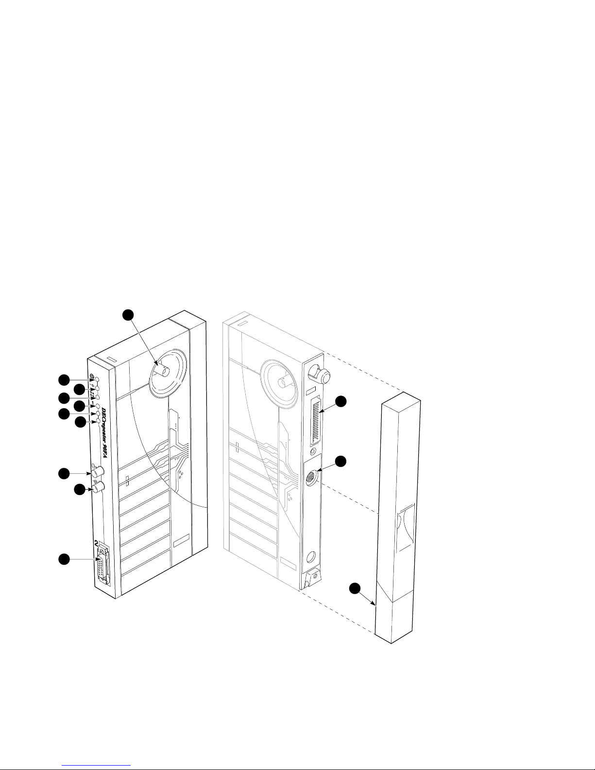
LEDs and Connectors
The front panel of the DECrepeater 90FA contains several indicator lights (LEDs)
and connectors. These LEDs and connectors are described in Table 1–1 and are
shown in Figure 1–1.
Figure 1–1 DECrepeater 90FA LEDs and Connectors
9
1
2
3
4
5
6
7
8
12
11
10
PJ-D120
REDUCE .45
1–2 Overview
ORG
13
LJ-02371-TI0
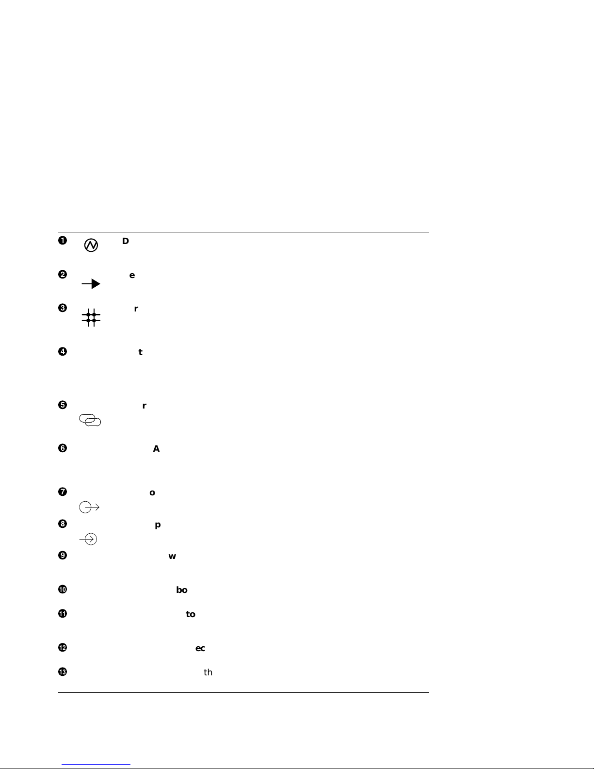
Table 1–1 DECrepeater 90FA LEDs and Connectors
!
"
#
$
%
&
'
DC OK monitors the voltage.
On: The +5.0 Vdc and +12.0 Vdc voltage is normal.
Off: The voltage is abnormal (as when a power failure occurs).
Network activity indicator monitors the network activity.
On: There is network activity.
Off: There is no network activity.
Port 0 status indicator monitors the status of port 0.
On: Port 0 is functional.
Off: Port 0 is not functioning or has been partitioned.
Flashing: Port 0 has been partitioned by management.
Port 1 status indicator monitors the status of port 1. See Table 5–1 in
Chapter 5, Troubleshooting, for more information.
On: Port 1 is functional.
Off: Port 1 is not functioning or has been partitioned.
Flashing: Port 1 has been partitioned by management.
Fiber-link status indicator monitors the optical link status of port 1.
See Table 5–2 in Chapter 5, for more information.
On: The link is operational.
Off: The link is not functioning.
Port 2 AUI status indicator monitors the status of port 2.
On: The port is operational.
Off: The port is not functioning.
Flashing: The port has been partitioned by management.
Fiber-optic transmit connector connects to the receive port of the other
fiber-optic device.
(
)
+>
+?
+@
+A
Fiber-optic receive connector connects to the transmit port of the other
fiber-optic device.
Port 0 network connector (BNC) connects the repeater to the work
group ThinWire segment. Not used when the repeater is installed in the
DEChub 90 backplane.
Port 2 Backbone Port AUI connector provides AUI connection to the
backbone port of the DECrepeater 90FA.
Power connector receives +5.0 V and +12.0 V from the DECrepeater 90FA
power supply. Not used when the repeater is installed in the DEChub 90
backplane.
Backplane connector provides network and power connections to the
DECrepeater 90FA when it is installed in the DEChub 90 backplane.
Back cover covers the backplane connector and mounting assembly. (Use
with standalone units only.)
Overview 1–3


2
Configuring the DECrepeater 90FA
This chapter contains some of the basic configuration rules and guidelines
that must be followed to correctly install the typical DECrepeater 90FA
configurations. For more detailed information about installing IEEE 802.3
compliant multisegment LANs, refer to Section 13 of the IEEE 802.3i-1990
standard.
Configuration Rules
The two basic constraints in IEEE 802.3 LAN configurations are segment lengths
and the number of repeaters between data terminal equipment (DTE). To ensure
the proper operation of the IEEE 802.3 physical layer and access methodology,
the network size must meet the round trip propagation delay budget.
Segment Length Constraints
Table 2–1 specifies the maximum segment lengths for the four possible types of
media.
Table 2–1 Segment Lengths
Media Type Maximum Segment Length (Meters)
Mixing (coaxial) 10Base2 (ThinWire) 185
10Base5 500
Link 10BaseT (twisted-pair) 100
FOIRL (fiber) 1000
10Base-FL (fiber) 2000
AUI Transceiver cable 50
Configuring the DECrepeater 90FA 2–1

Network Constraints
The overall network is constrained by the following IEEE 802.3 rules:
1. The transmission path between any two DTEs may consist of up to five
segments and four repeater sets (Figure 2–1).
When a network consists of five segments and four repeater sets, a maximum
of three of these segments may be mixing (coaxial) segments.
2. The total of all segments (up to five) shall not exceed 2500 meters.
Figure 2–1 shows an example of the maximum number of repeaters on a path
using coaxial segments and 10Base-FL segments.
2–2 Configuring the DECrepeater 90FA
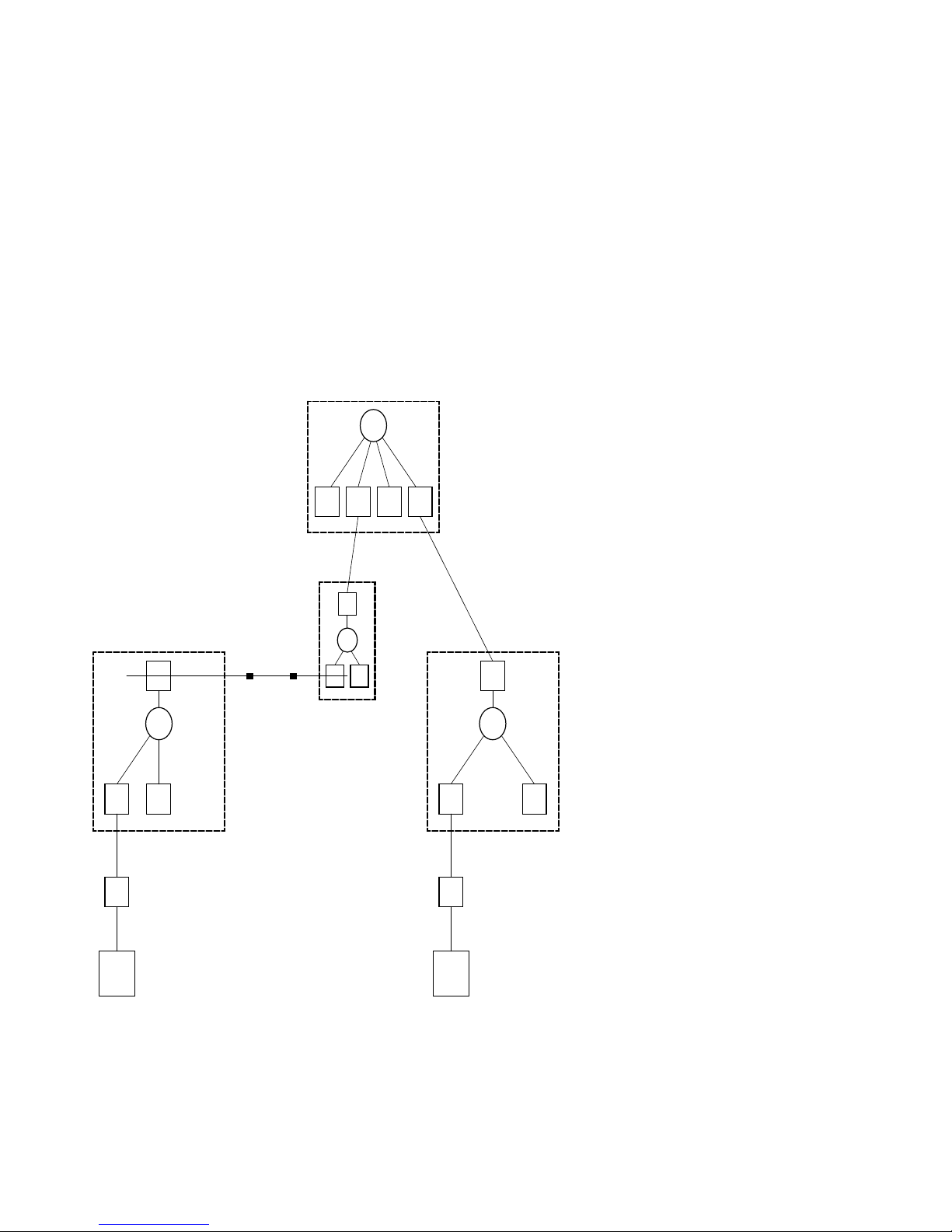
Figure 2–1 DECrepeater 90FA Repeater Path
DECrepeater 90FL
DECrepeater 90FA
10Base-FL
Link Segment
100 m
MAU
AUI
DTE
Fiber-Optic Link
Segment 500 m
Coax
10Base5
Segment
500 m
AUI AUI
DECrepeater 90FA
10Base2
Segment
185 m
MAU
AUI
DTE
Fiber-Optic Link
Segment 500 m
DECrepeater 90FA
LJ-02372-TI0
Configuring the DECrepeater 90FA 2–3
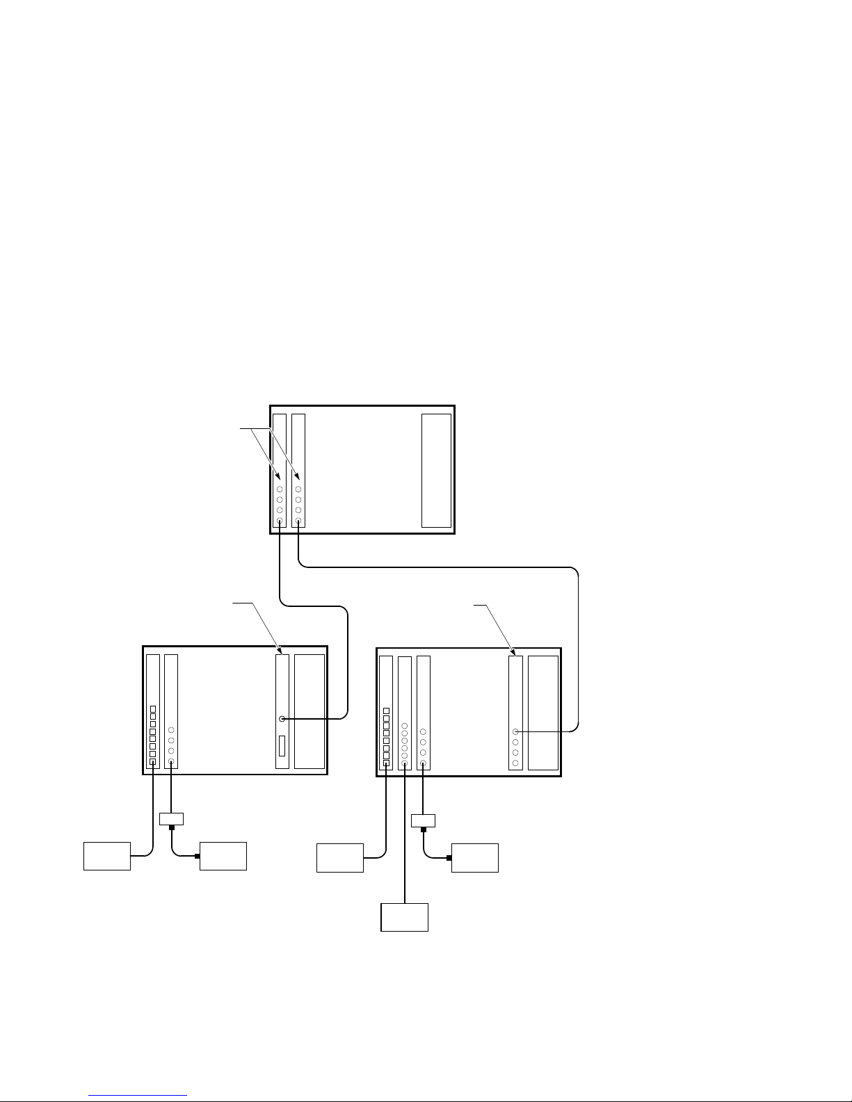
Figure 2–2 shows a DEChub 90 extended LAN configuration.
Figure 2–2 DECrepeater 90FA Typical DEChub 90 Configuration
DEChub 90
3
1
2
5 6
4
8
7
10BaseT
(Twisted-Pair)
Link Segment
100 m
DTE
DECrepeater 90FL
DECrepeater 90FA
DEChub 90
3
1
2
4
Fiber-Optic
Link Segment
500 m
MAU
AUI
DTE
56
Fiber-Optic Link Segment
1000 m
8
7
Power
Supply
10BaseT
(Twisted-Pair)
Link Segment
100 m
Power
Supply
DECbridge 90FL
3
1
2
Fiber-Optic
Link Segment
500 m
MAU
AUI
(ThinWire)
Mixing Segment
185 m
DTE
Fiber-Optic Link Segment
1000 m
DEChub 90
5 6
4
DTEDTE
8
7
Power
Supply
2–4 Configuring the DECrepeater 90FA
LJ-02373-TI0

In this configuration, the requirements of the network extend beyond the five
segments and four repeaters allowed by the IEEE 802.3 rules. This configuration
is supported by using a bridge to create an extended LAN. The two LANs on
either side of the bridge may each contain up to five segments and four repeaters;
however, they are able to communicate with one another as if they were on a
single LAN.
Installed Fiber Constraints
In addition to following the IEEE 802.3 rules that ensure proper protocol
operation, the user must also ensure that the fiber-optic cable plant is properly
designed. Although the IEEE 802.3 standard allows for a maximum length of
1000 meters (FOIRL) or 2000 meters (10Base-FL), the fiber-optic segments may
be limited by the following characteristics of installed fiber:
• Power budget
• Link-loss
• Wavelength
• Bandwidth
The maximum link distance could be further restricted by the number of splices,
interconnects, and cross-connect administration points. Refer to the DECconnect
System Fiber Optic Planning and Configuration guide for instructions on how to
calculate the link certification value for each segment.
Configuring the DECrepeater 90FA 2–5


3
Installation
Before you install the DECrepeater 90FA repeater, it is recommended that you
read this entire manual to become familiar with the features and configuration
rules of the DECrepeater 90FA. If problems occur during installation, refer
to Chapter 5, Troubleshooting. For additional information that may be useful
during installation, refer to Appendix A, Specifications and Parts List.
The DECrepeater 90FA may be installed on a desk top or table, mounted on a
wall by its back cover, or installed in a DEChub 90 backplane. The only tool
required for installation is a screwdriver. The screwdriver is used to remove the
back cover, which covers the backplane connector and mounting assembly, and to
mount the repeater or the power supply on the wall.
Site Considerations
The DECrepeater 90FA and its power supply can be placed in various locations,
including office areas, computer rooms, or wiring closets, as long as the
environmental requirements are met. These requirements are provided in
Table A–2, Operating Environment, in Appendix A.
Standalone Installation
To install the DECrepeater 90FA on a desk top or table, make sure that the
air circulation around the DECrepeater 90FA does not become obstructed by
papers or other materials. Refer to the environmental specifications provided in
Table A–2 in Appendix A.
Installation 3–1
Mount the DECrepeater 90FA on a Wall
To install the DECrepeater 90FA as a standalone wall-mount unit, perform the
following procedure:
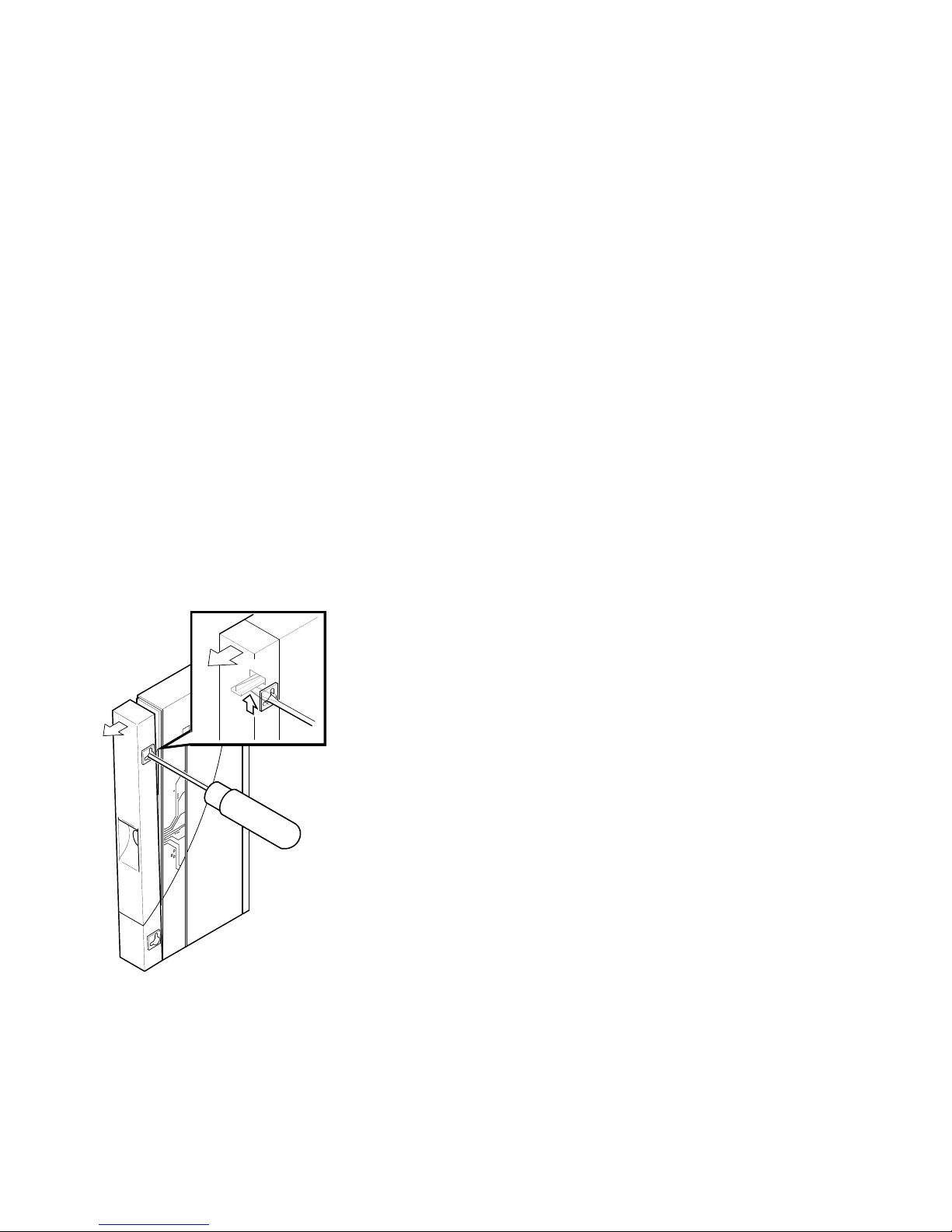
1. Remove the cover (if necessary).
a. Insert a small screwdriver into the top mounting hole on the cover
(Figure 3–1).
b. Lift the internal latch with the screwdriver, then pull the cover away and
down from the top of the unit.
Figure 3–1 Removing the Back Cover
LJ-00320-TI0
3–2 Installation
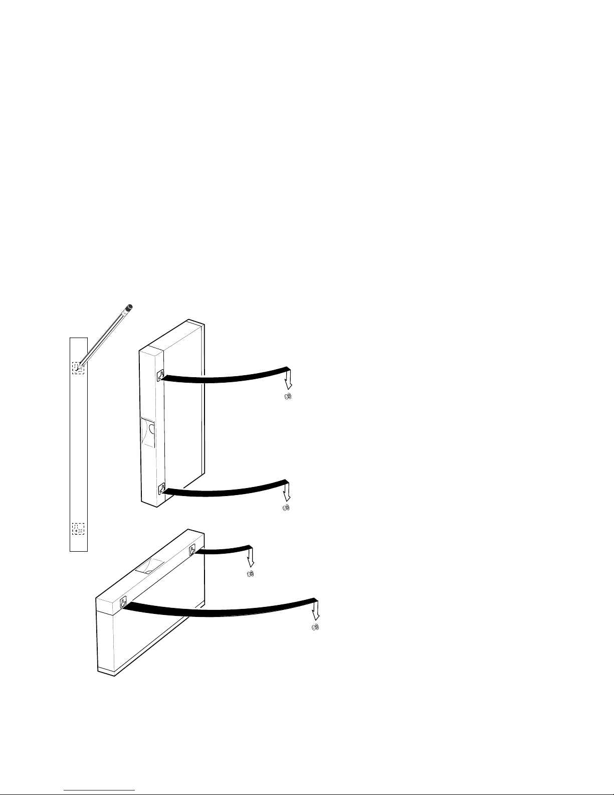
2. Use the mounting holes on the back cover to determine the placement for the
mounting screws on the wall (Figure 3–2).
3. Secure the back cover to the wall using the mounting screws.
Figure 3–2 Mounting Screws
LJ-00701-TI0
Installation 3–3

The screws should be tight enough to provide resistance if you try to remove
the back cover from the wall. However, do not make the screws so tight that
the cover is distorted or cannot be removed from the wall.
4. Remove the back cover from the wall.
5. Attach the back cover to the repeater.
6. Mount the repeater onto the mounting screws.
Standalone Installation Connections
To make the DECrepeater 90FA standalone installation connections, perform the
following procedure and refer to Figure 3–3:
1. Connect the cable from the power supply to the 7-pin power connector on the
DECrepeater 90FA. Align the power symbol on the dc power connector with
the power symbol on the DECrepeater 90FA and push straight in.
2. Connect the DECrepeater 90FA to the power source.
For 120/240 V power outlets, connect the power supply cord to the modular
power supply, then to the wall outlet.
3. If desired, connect the Ethernet ThinWire segment to a T-connector; connect
the T-connector to the port 0 BNC network connector. Terminate the
T-connector using a 50-ohm terminator or extend the Ethernet segment
to the next device.
The port 0 status activity LED should be on or flashing to indicate the
amount of traffic on the network. The LED intensity varies with the amount
of traffic: the more traffic, the brighter the LED will appear.
4. Connect the AUI cable to port 2, if required by the application.
5. Connect the fiber-optic cables to port 1 using 2.5-millimeter ST type bayonet
connectors, if required by the application.
The DECrepeater 90FA is now installed.
3–4 Installation
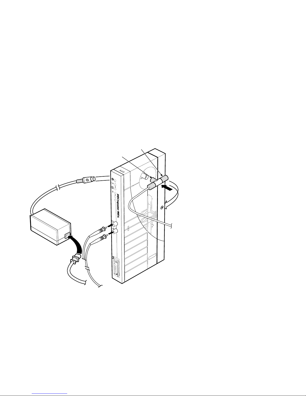
Figure 3–3 Standalone Installation
T-Connector
Fiber Link
50-Ohm
Terminator
To Fiber
Network
LJ-02374-TI0A
Installation 3–5
 Loading...