

Digital Equipment DECrepeater 900TM, DECrepeater 900GM Installation And Configuration Manual

DECrepeater 900TM
Installation and Configuration
Part Number: EK–DETMM–IN. B01
August 1994
This manual describes how to install and configure
the DECrepeater 900TM module.
Revision/Update Information: This is a revised manual.

Copyright
August 1994
The information in this document is subject to change without notice and should not be construed as a
commitment by Digital Equipment Corporation. Digital Equipment Corporation assumes no responsibility
for any errors that may appear in this document.
Copyright 1994 by Digital Equipment Corporation.
All rights reserved. Printed in U.S.A.
The postage-paid Reader’s Comments form at the back of this document requests your evaluation of this
document to assist us in preparing future documentation.
The following are trademarks of Digital Equipment Corporation: DEC, DEChub, DEChub ONE,
DECndu, DECndu Plus, DECrepeater, Digital, HUBwatch, MultiSwitch, OpenVMS, ThinWire, ULTRIX,
VAX, VMS, and the DIGITAL logo.
MS-DOS is a registered trademark of Microsoft Corporation.
FCC NOTICE — Class A Computing Device:
This equipment generates, uses, and may emit radio frequency energy. The equipment has been type
tested and found to comply with the limits for a Class A computing device pursuant to Subpart J of Part 15
of FCC Rules, which are designed to provide reasonable protection against such radio frequency
interference when operated in a commercial environment. Operation of this equipment in a residential area
may cause interference; in which case, measures taken to correct the interference are at the user’s
expense.
VCCI NOTICE — Class 1 Computing Device:
This equipment is in the 1st Class category (information equipment to be used in commercial and/or
industrial areas) and conforms to the standards set by the Voluntary Control Council for Interference by
Data Processing Equipment and Electronic Office Machines aimed at preventing radio interference in
commercial and/or industrial areas. Consequently , when used in a residential area or in an adjacent area
thereto, radio interference may be caused to radios and TV receivers.
Read the instructions for correct handling.
CE NOTICE – Class A Computing Device:
Warning!
This is a Class A product. In a domestic environment this product may cause radio interference, in which
case the user may be required to take adequate measures.
Achtung!
Dieses ist ein Gerät der Funkstörgrenzwertklasse A. In Wohnbereichen können bei Betrieb dieses
Gerätes Rundfunkstörungen auftreten, in welchen Fällen der Benutzer für entsprechende
Gegenmaßnahmen verantwortlich ist.
Attention!
Ceci est un produit de Classe A. Dans un environment domestique, ce produit risque de créer des
interférences radioélectriques, il appartiendra alors à l’utilisateur de prendre les mesures spécifiques
appropriées.

iii
Contents
Safety
Introduction 1. . . . . . . . . . . . . . . . . . . . . . . . . . . . . . . . . . . . . . . . . . . . . . . . . .
Features 1. . . . . . . . . . . . . . . . . . . . . . . . . . . . . . . . . . . . . . . . . . . . . . . . . . .
Front Panel 3. . . . . . . . . . . . . . . . . . . . . . . . . . . . . . . . . . . . . . . . . . . . . . . . . . .
Back Panel 4. . . . . . . . . . . . . . . . . . . . . . . . . . . . . . . . . . . . . . . . . . . . . . . . . . .
Installing the Module 5. . . . . . . . . . . . . . . . . . . . . . . . . . . . . . . . . . . . . . . . .
Removing the Module 8. . . . . . . . . . . . . . . . . . . . . . . . . . . . . . . . . . . . . . . .
Configuring the Module 9. . . . . . . . . . . . . . . . . . . . . . . . . . . . . . . . . . . . . .
Setup Port Description 9. . . . . . . . . . . . . . . . . . . . . . . . . . . . . . . . . . . . . . . .
Setup Port Device Cabling 9. . . . . . . . . . . . . . . . . . . . . . . . . . . . . . . . . . . . .
Accessing the Setup Port 9. . . . . . . . . . . . . . . . . . . . . . . . . . . . . . . . . . . . . .
Start Redirect Mode 12. . . . . . . . . . . . . . . . . . . . . . . . . . . . . . . . . . . . . . . . . .
DECrepeater 900TM Installation Menu (DEChub ONE Options) 13. . . . . .
DECrepeater 900TM Installation Menu (DEChub 900 Options) 14. . . . . . .
Description of Menu Options 15. . . . . . . . . . . . . . . . . . . . . . . . . . . . . . . . . . .
LED Descriptions 35. . . . . . . . . . . . . . . . . . . . . . . . . . . . . . . . . . . . . . . . . . . . .
Problem Solving Using the LEDs 36. . . . . . . . . . . . . . . . . . . . . . . . . . . . .
Normal Powerup 36. . . . . . . . . . . . . . . . . . . . . . . . . . . . . . . . . . . . . . . . . . . .
Problem Solving 36. . . . . . . . . . . . . . . . . . . . . . . . . . . . . . . . . . . . . . . . . . . .

iv
Contents (Cont.)
Connector Pin Assignments 39. . . . . . . . . . . . . . . . . . . . . . . . . . . . . . . . .
Internal Crossover Configuration 39. . . . . . . . . . . . . . . . . . . . . . . . . . . . . . . .
External Crossover Configuration 39. . . . . . . . . . . . . . . . . . . . . . . . . . . . . . .
H8571-J Adapter 40. . . . . . . . . . . . . . . . . . . . . . . . . . . . . . . . . . . . . . . . . . . .
H8575-A Adapter 40. . . . . . . . . . . . . . . . . . . . . . . . . . . . . . . . . . . . . . . . . . . .
10BaseT Port (8-pin MJ) Connector 41. . . . . . . . . . . . . . . . . . . . . . . . . . . . .
Product Specifications 42. . . . . . . . . . . . . . . . . . . . . . . . . . . . . . . . . . . . . . .
Associated Documents 44. . . . . . . . . . . . . . . . . . . . . . . . . . . . . . . . . . . . . .
Tables
1 The Downline Upgrade (DLU) Process 26. . . . . . . . . . . . . . . . . . . . . . . . .
2 Module LED States 35. . . . . . . . . . . . . . . . . . . . . . . . . . . . . . . . . . . . . . . .
3 Problem Solving Using the LEDs 36. . . . . . . . . . . . . . . . . . . . . . . . . . . . .
4 DECrepeater 900TM Operating Specifications 42. . . . . . . . . . . . . . . . . .
5 Acoustical Specifications 43. . . . . . . . . . . . . . . . . . . . . . . . . . . . . . . . . . .

v
Safety
!
Any warning or caution that appears in this manual is defined as follows:
WARNING Contains information to prevent personal injury.
CAUTION Contains information to prevent damage to equipment.
VORSICHT Enthält Informationen, die beachtet werden müssen,
um den Benutzer vor Schaden zu bewahren.
ACHTUNG Enthält Informationen, die beachtet werden müssen,
um die Geräte vor Schaden zu bewahren.
DANGER Signale les informations destinées à prévenir les acci-
dents corporels.
ATTENTION Signale les informations destinées à prévenir la détéri-
oration du matériel.
AVISO Contiene información para evitar daños personales.
PRECAUCION
Contiene información para evitar daños al equipo.

vi
Safety
!
(Cont.)
CAUTION
!
This action deletes all configured settings and replaces
them with factory default values. All configuration settings
will be lost. [Page 16.]
ACHTUNG Bei diesem Vorgang werden alle Konfigurationseinstel-
lungen gelöscht und die Werkseinstellungen wieder eingesetzt. Alle Konfigurationsdaten gehen verloren.
ATTENTION Cette action supprime tous les paramètres de configura-
tion et les remplace par des valeurs prédéfinies. Tous
les paramètres de configuration seront perdus.
PRECAUCION
Esta intervención borrará todos los parámetros de configuración y los sustituirá por valores por defecto definidos
de fábrica. Se perderán todos los parámetros de configuración.

vii
Safety
!
(Cont.)
CAUTION
!
If power is interrupted during Stage 3 of the DLU process,
the firmware image can become corrupted. Do not turn off
power to the unit or perform any action that can cause the
unit to lose power during Stage 3 of the DLU process.
[Pages 25, 27, and 30.]
ACHTUNG Sollte während der Phase 3 des DLU–Prozesses eine
Unterbrechung der Stromversorgung eintreten, kann das
Firmwareprogramm zerstört werden. Aus diesem Grunde
wird dringend empfohlen, Vorkehrungen zu treffen, daß
während der Durchführung dieser Phase 3 die Systemeinheit weder ausgeschaltet noch die Stromversorgung
unterbrochen werden kann.
ATTENTION L’image du microprogramme risque d’être corrompue, en
cas de coupure de courant au cours de l’étape 3 du processus DLU. Ne mettez pas l’unité hors tension et n’exécutez aucune action risquant d’entraîner une coupure
d’alimentation au cours de cette étape.
PRECAUCION
Si se interrumpe el suministro eléctrico durante la Etapa
3 del proceso DLU, puede dañarse la imagen del firmware. No se debe apagar la unidad ni realizar ninguna
operación que pueda causar una interrupción del suministro de la unidad durante la Etapa 3 del mencionado
proceso.


DECrepeater 900TM Installation and Configuration 1
Introduction
The DECrepeater 900TM (also referred to in this manual as the module) is a
full-height, 32-port, 10BaseT, Ethernet repeater.
In this manual, the term Ethernet is Digital’s term for its product compatibility with the
ISO 8802-3/ANSI/IEEE 802.3 standards and the Ethernet standards for Carrier
Sense Multiple Access with Collision Detection (CSMA/CD) local area networks
(LANs).
To give your workgroup LAN media flexibility and connectivity, the module can be
configured into a DEChub 900 MultiSwitch (also referred to in this manual as the
DEChub 900). One or more DECrepeater 900TM modules (up to 8) can be installed
into the DEChub 900. The module can also serve as a standalone unit when
configured with a DEChub ONE docking station (see the DEChub ONE Installation
manual).
When the module is installed into a DEChub 900 or into a DEChub ONE, the
module’s hot-swap capability allows you to install or remove the module without
turning off power.
The front panel provides 32 10BaseT ports using 8-pin modular jack (MJ) connectors
that support 100-ohm unshielded twisted pair (UTP) and 100-ohm shielded
twisted-pair (STP) cables. The module’s front panel light-emitting diodes (LEDs)
indicate the operating status of the module, the ports, and the network.
Features
Your DECrepeater 900TM module includes the following features:
• Access to ThinWire 10Base2 segment in the DEChub 900 MultiSwitch or to the
AUI port in the DEChub ONE docking station.
• Backplane access to multiple LANs through one of six flexible channels in the
DEChub 900.
• Automatic module self-test at powerup.
• Port-level packet address security.

2 DECrepeater 900TM Installation and Configuration
Introduction (Cont.)
• Momentary LED cycle switch on the front panel enables you to observe one
bank of Port State LEDs at a time.
• In-band Simple Network Management Protocol (SNMP) management.
• Out-of-Band Management (OBM) using SNMP over Serial Line Internet Proto-
col (SLIP) through the OBM connector on the DEChub 900 or the DEChub ONE
docking station in addition to the normal in-band management.
• Built-in SNMP agent supports the following management information bases
(MIBs):
– Internet Engineering Task Force (IETF) Repeater MIB (RFC 1516)
– Ethernet-like Interface Type MIB (RFC 1398)
– Digital Extended Repeater MIB
– DEChub 900 Public Common MIB
– MIB II (RFC 1213)
• Manageability using any generic SNMP management application that supports
the MIBs listed above.
• Upgradeable device firmware (in nonvolatile Flash memory) using Trivial File
Transfer Protocol (TFTP) with Digital’s Network Device Upgrade (DECndu) Plus
utility or through the setup port with any TFTP server.
• User-friendly advanced Graphical User Interface (GUI) manageability with
Digital’s HUBwatch Network Management Station (NMS) application.

3
DECrepeater 900TM Installation and Configuration
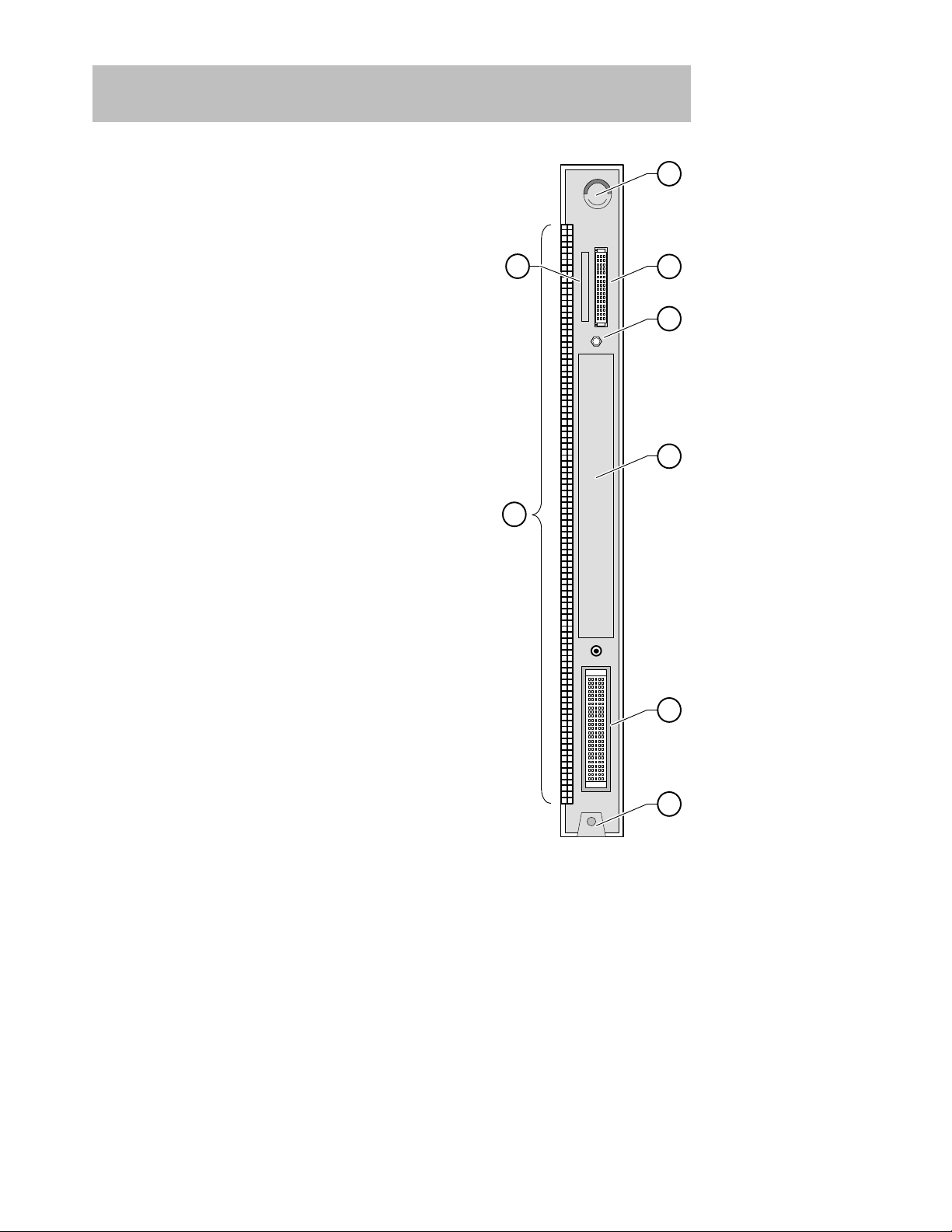
Front Panel
1) Power
LED — Lights when the module has
power.
2) Module OK
LED — Lights when the module
passes self-test. If the module fails self-test, the Module OK
LED remains off.
3) Network OK
LED — Indicates the status of the
backplane ThinWire port on the DEChub 900 or of
the AUI port on the DEChub ONE docking station.
4) Network Activity
LED — Indicates network
traffic level.
5) Port State LEDs — The LEDs (labeled 1 through 8)
show the status of one of the four banks of ports, depending on the state of the Bank Indicator LEDs.
6) Bank Indicator LEDs — The LEDs (labeled A
through D) light one at a time for a few seconds, indicating which bank of connectors, is currently displaying its port connection status on the eight Port State
LEDs.
NOTE: For more information about the
module’s LEDs, refer to the section
titled LED Descriptions.
7) Momentary LED cycle switch — Stops and starts
the LED status scanning of the Bank Indicator LEDs
during operation.
8) 10BaseT (8-pin MJ) port connectors — Connectors for ports 1 to 32. Support both UTP and STP
cabling.
LKG-7455-93I
2
3
8
6
7
5
1
4
LKG-8709-93I
7
1
2
3
8
4
5
6
4
DECrepeater 900TM Installation and Configuration
Back Panel
1) Locking tab — Locks the module into a DEChub 900
backplane or into the DEChub ONE docking station.
It also contains the hot-swap switch lever.
2) 48-pin connector — Provides network and power
connections to the module when the module is
installed into a DEChub 900 or a DEChub ONE docking station.
3) Grounding bolt — Provides a chassis grounding
connection between the module and a DEChub 900
or DEChub ONE docking station.
4) Manufacturing label — Lists the module part number, serial number , revision level, and power requirements.
5) 160-pin connector — Provides network and power
connections to the module when the module is
installed into a DEChub 900 or DEChub ONE docking station.
6) Mounting tab — Secures the module to the backplane when the module is installed into a DEChub
900 or DEChub ONE docking station.
7) Grounding fingers — Provides additional chassis
grounding between the module and a DEChub 900
or DEChub ONE docking station.
8) Address label — Contains the module’s 48-bit
Ethernet hardware address.
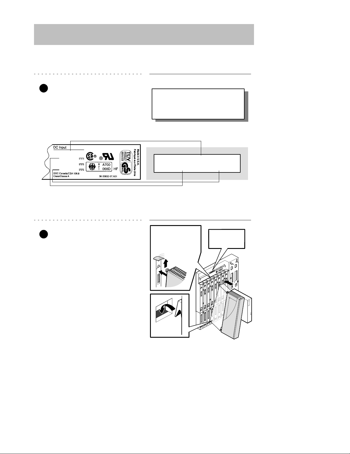
Module’s Manufacturing
Label (Example)
If any of the module’s power requirements
exceed the values shown in the status display, add another power supply (see the
DEChub 900 MultiSwitch Owner’s Manual).
Hub Manager Status
Display (Example)
LKG–9346–94I
Available: 90.5 W
5V: 13.0 A, 15V: 3.5 A
27.5 W
5 V
12 V
15 V
4.0 A
0.1 A
0.5 A
5
DECrepeater 900TM Installation and Configuration
Installing the Module
The module hot-swap feature allows you to install the module into the DEChub 900 or
DEChub ONE docking station without turning off power . Seating the module initiates
the powerup sequence if enough power is available.
1 Compare your module’s power
requirements with the values
shown in the Hub Manager status
display (see examples).
NOTE: The 12V power in the DEChub 900 is derived from the
15V power source. Although it is listed separately in the
product specifications, the 12V requirements are
included in the 15V power total.
2 Seat the module into the
DEChub 900.
a. Place the module’s mounting
tab into a mounting slot on the
DEChub 900.
b. Pivot the module on the mount-
ing tab and align the connectors.
c. Firmly push the module onto the
backplane connectors until the
release lever clicks.
d. Press down on the release lever
to ensure that it is locked.
Mounting tab
LKG–8711–93I
Release lever clicks
when module is
seated.
Hub Manager
status display
6
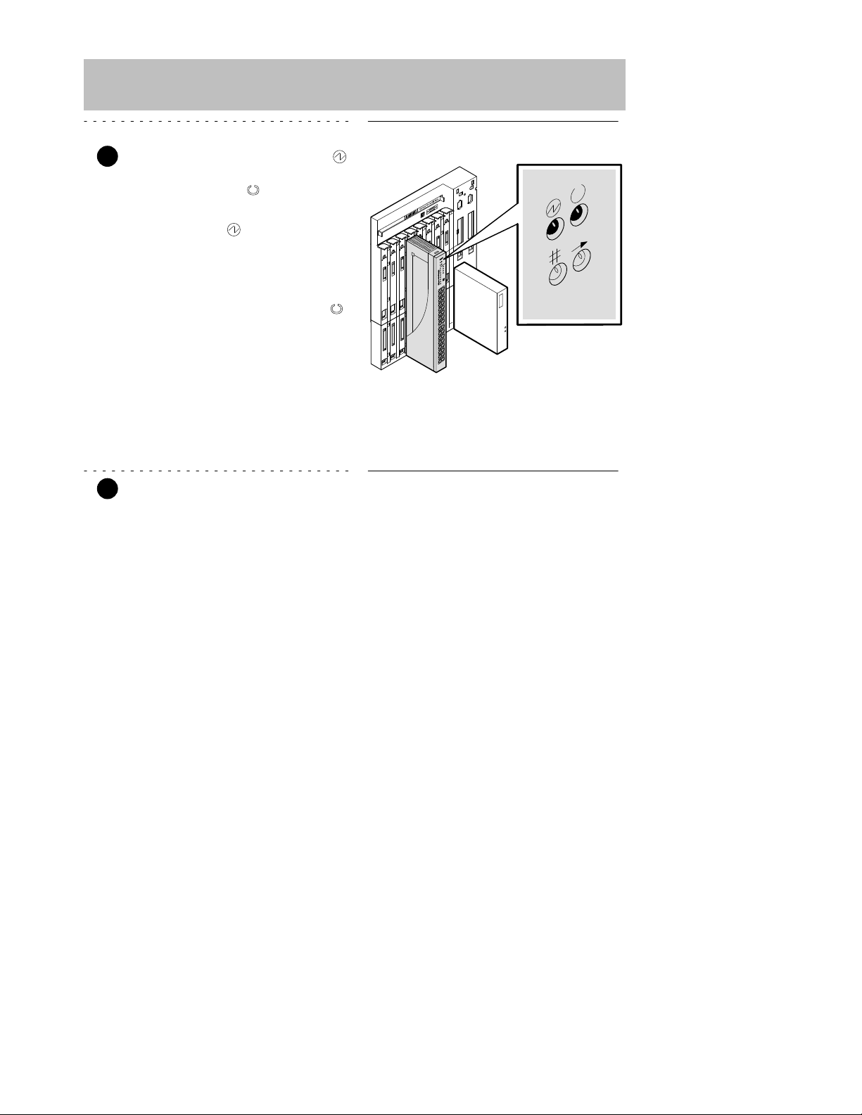
DECrepeater 900TM Installation and Configuration
Installing the Module (Cont.)
3 Verify that the module’s Power
LED lights immediately, and that
the Module OK
LED lights
within 1 minute.
a. The Power
LED lights when
the power is applied, then the
module performs a self-test.
b. After the module completes
self-test, the Module OK
LED lights and remains lit, then
the Hub Manager status
display shows:
DECrepeater 900TM
up
NOTE: If the LEDs do not operate as described, refer to the
section entitled Problem Solving Using the LEDs.
4 Connect the 10BaseT Port cable.
The DECrepeater 900TM module uses crossover 10BaseT (8-pin MJ) port connectors.
The appropriate UTP/STP cable type, crossover or straight-through, is required to
ensure that the module’s transmit/receive signals connect correctly to the
transmitter/receiver of the connected device.
Before connecting the cables to the module, note the following:
• If the device you are connecting to the module uses straight-through connectors,
use straight-through cables.
• If the device you are connecting to the module uses crossover connectors, use
crossover cables.
• The sum of crossovers must always equal an odd number.
NOTE: Digital’s straight-through cables are marked (=);
crossover connectors (and cables) are marked (X).
LKG-9345-93I

7
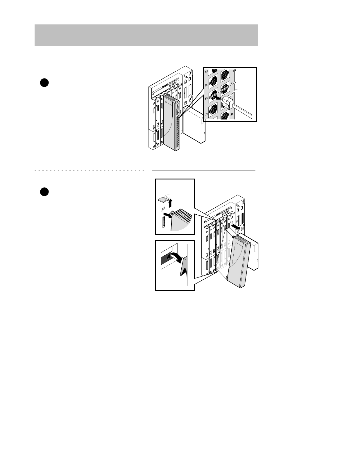
DECrepeater 900TM Installation and Configuration
Installing the Module (Cont.)
If you need help determining the appropriate cable type to use, refer to the section titled
Connector Pin Assignments.
To connect the UTP/STP cables, complete the following steps:
a. Align the release tab on the
cable plug with the keyway on
the module’s 8-pin MJ connector.
b. Insert the plug into the connec-
tor, ensuring that the release tab
snaps into the locked position.
NOTE: To disconnect the UTP/STP cables, press the release
tab on the 8-pin MJ connector, then disconnect the
cable.
After all cables are installed, go to the section titled Configuring the Module.
LKG–9347-93I
Keyway
Release
tab
LKG–9348-93I
Keyway
Release
tab
8
DECrepeater 900TM Installation and Configuration
Removing the Module
1 Disconnect all the UTP/STP
cables from the module.
a. To remove the UTP/STP
cables, press the release tab
on the 8-pin MJ connector.
b. Disconnect the cable.
2 Unseat the module from the
DEChub 900.
a. Lift the release lever located on
the top of the DEChub 900 slot.
b. Pivot the module back on its
bottom mounting tab, and disengage the module from the
backplane.
Mounting tab
LKG–8717-93I
Lift release lever

9
DECrepeater 900TM Installation and Configuration
Configuring the Module
Setup Port Description
The setup port (on the DEChub 900 MultiSwitch or the DEChub ONE docking
station) allows you to access and set DECrepeater 900TM parameters. This section
describes how to access the module from either port and how to set those
parameters.
NOTE: The setup port screen displays illustrated in this manual
may vary slightly from the actual screen displays on your
setup port device.
The signals from the DEChub 900 Hub Manager setup port and from the DEChub
ONE docking station setup port conform to the EIA-232D signaling standard at 9600
baud. To the user, the port appears as a data terminal equipment (DTE) device.
NOTE: Devices that use the EIA-423 signaling standard are
compatible with the DEChub 900 Hub Manager setup
port.
Setup Port Device Cabling
The setup port on the DEChub 900 MultiSwitch or the DEChub ONE docking station
can be connected to a setup port device (a terminal or personal computer), using the
following cables and adapters.
Cable/Adapter Type
Connecting Device
BN24H-xx
1
A terminal with a 6-pin MMJ connector
BN24H-xx1/H8575-A A terminal with a 25-pin D-Sub connector
BN24H-xx1/H8571-J
A PC with a 9-pin D-Sub communications port
1
xx indicates cable length in meters.
Accessing the Setup Port
To access the setup port on the DECrepeater 900TM module, do the following:
1. Ensure that the transmit and receive baud rates on the setup port device are
set to 9600 baud.
2. Connect the setup port device to the setup port connector on either the
DEChub 900 or the DEChub ONE docking station (see illustration).

10
DECrepeater 900TM Installation and Configuration
Configuring the Module (Cont.)
Setup port
LKG–8718-93I
DEChub ONE
Setup port
DEChub 900 MultiSwitch
OBM port
OBM port
BN24H cable
H8571-J
H8575-A
To setup port device
BN24H
cable
H8571-J
H8575-A
T o setup port device

Choose option 13, then
go to the section titled
Start Redirect Mode.
The DECrepeater 900TM does not
support Option [9] Downline
Upgrade from this menu.
You must choose Option [13]
Start Redirect Mode to perform
a downline upgrade to this module.
11
DECrepeater 900TM Installation and Configuration
Configuring the Module (Cont.)
3. Press
Return
on the setup port device a few times until a menu appears.
a. If the module is connected to the setup port on the DEChub ONE dock-
ing station, the DECrepeater 900TM INSTALLATION MENU ap-
pears. Go to the section titled DECrepeater 900TM Installation Menu
(DEChub ONE Options).
b. If the module is connected to the Hub Manager setup port on the
DEChub 900, the DEChub 900 MultiSwitch INSTALLATION
MENU appears (see following example).
The following is an example of the DEChub 900 MultiSwitch INSTALLATION
MENU:
DEChub 900 MultiSwitch
DEChub 900 MultiSwitch INSTALLATION MENU
[1] Reset with Factory Defaults
[2] Reset with Current Settings
[3] Show Current Settings
[4] Set SNMP Read/Write Community
[5] Add SNMP Trap Addresses
[6] Delete SNMP Trap Addresses
[7] Dump Error Log
[8] Set In-Band Interface IP Address
[9] Downline Upgrade
[10] Set Out-of-Band Interface IP Address
[11] Set Out-of-Band Interface Port Speed
[12] Start Event Display Mode
[13] Start Redirect Mode
Enter selection : 13
Return
c. Choose option 13, then go to the section titled Start Redirect Mode.

Enter the number
of the slot where
the module is
installed.
12
DECrepeater 900TM Installation and Configuration
Configuring the Module (Cont.)
Start Redirect Mode
The Start Redirect Mode option redirects the DEChub 900 Hub Manager setup
port to the setup port of any network module that supports this function (such as the
DECrepeater 900TM) that is installed into the DEChub 900. Choosing this option
allows you to configure or obtain status of an installed network module by accessing
the specified network module’s installation menu.
After you choose the Start Redirect Mode option from the DEChub 900
MultiSwitch INSTALLATION MENU, the screen prompts you for a slot number
as shown in the following example.
The following example shows how to select a slot number (user response is shown in
boldface type):
Enter selection: 13
Enter the slot number for redirection (1–8): 3
Return
Setup port redirected to 3: DECrepeater 900TM
Attempting to connect ...
Connection successful!
After you press
Return
, the DECrepeater 900TM INSTALLATION MENU appears
on your screen. Go to the section titled DECrepeater 900TM Installation Menu
(DEChub 900 Options).

Choose an option,
then go to the section
titled Description of
Menu Options.
If you need to assign
an IP address to the
module, choose this
option.
13
DECrepeater 900TM Installation and Configuration
Configuring the Module (Cont.)
DECrepeater Installation Menu (DEChub ONE Options)
This section shows the options available from the DECrepeater 900TM
INSTALLATION MENU when the module is installed into the DEChub ONE docking
station.
The following is an example of the DECrepeater 900TM INSTALLATION MENU:
DECrepeater 900TM
DECrepeater 900TM INSTALLATION MENU
[1] Reset with Factory Defaults
[2] Reset with Current Settings
[3] Show Current Settings
[4] Set SNMP Read/Write Community
[5] Add SNMP Trap Addresses
[6] Delete SNMP Trap Addresses
[7] Dump Error Log
[8] Set In-Band Interface IP Address
[9] Set In-Band Interface Default Gateway Address
[10] Downline Upgrade
[11] Set Out-of-Band Management (OBM) Interface IP Address
[12] Set Out-of-Band Management (OBM) Port Speed
Enter selection : 1
Return

Choose an option,
then go to the section
titled Description of
Menu Options.
If you need to assign
an IP address to the
module, choose this
option.
Indicates the DEChub 900
slot number where the
module is installed.
14
DECrepeater 900TM Installation and Configuration
Configuring the Module (Cont.)
DECrepeater Installation Menu (DEChub 900 Options)
This section shows the options available from the DECrepeater 900TM
INSTALLATION MENU when the module is installed into the DEChub 900.
The following is an example of the DECrepeater 900TM INSTALLATION MENU:
DECrepeater 900TM – slot 3
DECrepeater 900TM INSTALLATION MENU
[1] Reset with Factory Defaults
[2] Reset with Current Settings
[3] Show Current Settings
[4] Set SNMP Read/Write Community
[5] Add SNMP Trap Addresses
[6] Delete SNMP Trap Addresses
[7] Dump Error Log
[8] Set In-Band Interface IP Address
[9] Set In-Band Interface Default Gateway Address
[10] Downline Upgrade
[Ctrl/C] Return to DEChub 900 MultiSwitch INSTALLATION MENU
Enter selection : 1
Return

15
DECrepeater 900TM Installation and Configuration
Configuring the Module (Cont.)
Description of Menu Options
This section describes the menu options that are available from the DECrepeater
900TM INSTALLATION MENU. Note that the out-of-band menu options apply to the
module only when it is in standalone mode (configured in a DEChub ONE docking
station).
[1] Reset with Factory Defaults
This option resets the module, causing most of the module’s configured NVRAM
parameters to be initialized to factory default values.
Following are some examples of the module’s configured NVRAM parameters that
are reset to factory defaults:
• SNMP read/write community –– this name is reset to PUBLIC.
• SNMP trap addresses ––all SNMP trap addresses are deleted.
• In-band interface IP address –– this address is deleted.
• In-band interface default gateway address –– this address is deleted.
• Out-of-band interface IP address –– this address is deleted.
• Out-of-band interface port speed –– reset to 9600.
Following are the only parameters that are not reset:
• Serial number
• Reset count
• Error log data

16
DECrepeater 900TM Installation and Configuration
Configuring the Module (Cont.)
[1] Reset with Factory Defaults (Cont.)
CAUTION
!
This action deletes all configured settings and replaces
them with factory default values. All configuration
settings will be lost.
NOTE: Allow approximately 1 minute for the module to reset
and complete self-test.
The following is an example of the dialog associated with this option (user response
is shown in boldface type):
Enter selection : 1
DECrepeater 900TM – slot 3
RESET WITH FACTORY DEFAULTS
* * * * * * * * * * * * * * * * * * * * * * * * * * * * * *
* IMPORTANT! IMPORTANT! IMPORTANT! *
* * * * * * * * * * * * * * * * * * * * * * * * * * * * * *
* This selection will delete the current configuration *
* settings and reset the system with the factory default *
* settings. All configuration settings will be lost. *
* * * * * * * * * * * * * * * * * * * * * * * * * * * * * *
Press Y to confirm [N] :
Return
Press Return for Main Menu ...

17
DECrepeater 900TM Installation and Configuration
Configuring the Module (Cont.)
[2] Reset with Current Settings
This option resets the module but leaves the module’s configured NVRAM
parameters at their current values.
NOTE: Allow approximately 1 minute for the module to reset
and complete self-test.
The following is an example of the dialog associated with this option (user response
is shown in boldface type):
Enter selection : 2
DECrepeater 900TM – slot 3
RESET WITH CURRENT SETTINGS
This selection will reset your system with the
current configuration settings.
Press Y to confirm [N] :
Return
Press Return for Main Menu ...

18
DECrepeater 900TM Installation and Configuration
Configuring the Module (Cont.)
[3] Show Current Settings
This option shows the module’s current settings.
NOTE: If the module is being configured for the first time, some
fields will be blank.
The following is an example of the display associated with this option:
Enter selection : 3
DECrepeater 900TM – slot 3
DECrepeater 900TM, Ethernet Rptr SNMP, HW=v1,RO=v1,SW=v1.1
SysUpTime : 01:39:11 14 resets
SNMP Read/Write Community : public
SNMP Trap Addresses : Not Configured
Status of Last Downline Upgrade : No Status
00:00:44 28 resets
In-Band Interface Hardware Address : 08–00–2B–A3–4C–70
In-Band Interface IP Address : 16.20.216.181
In-Band Interface Default Gateway Address : Not Configured
SNMP Port Traps Enabled
Press Return for Main Menu ...

19
DECrepeater 900TM Installation and Configuration
Configuring the Module (Cont.)
[4] Set SNMP Read/Write Community
This option prompts you to enter the module’s read/write community name.
The format for a community name is a string consisting of 4 to 31 printable ASCII
characters. This community name can be used by SNMP managers for read/write
access control.
The following is an example of an SNMP read/write community name: fonzi1974
The following is an example of the dialog associated with this option (user response
is shown in boldface type):
Enter selection : 4
DECrepeater 900TM – slot 3
SET SNMP READ/WRITE COMMUNITY
Format: The format for a community name is a string,
consisting of four to thirty–one printable ASCII
characters, that describes the relationship between an
SNMP agent and one or more SNMP managers. The string
defines the authentication mechanism that is employed
to validate the use of the community by the sending
SNMP entity.
Enter the community string [public] : fonzi1974
Return
SNMP Read/Write community string set.
Press Return for Main Menu ...

Enter the SNMP trap address that you have
chosen, then press Return.
Appears only if the module has
been previously configured.
20
DECrepeater 900TM Installation and Configuration
Configuring the Module (Cont.)
[5] Add SNMP Trap Addresses
This option prompts you to enter IP addresses to which SNMP traps will be sent from
the DECrepeater 900TM module.
The format for an SNMP trap address is the standard 4-octet dotted decimal notation,
where each octet of the address is represented as a decimal value, separated by a
decimal point (.).
The following is an example of an SNMP trap address: 16.20.54.156
The following is an example of the dialog associated with this option (user response
is shown in boldface type):
Enter selection : 5
DECrepeater 900TM – slot 3
ADD SNMP TRAP ADDRESSES
Format: The standard 4 octet dotted decimal notation in which
each octet of the address is represented as a decimal
value, separated by a ’.’ character.
example: 16.20.54.156
Configured SNMP Trap Addresses: 16.20.216.81
Trap address [] : 16.20.54.156
Return
Trap address added! Add another? [none] :
Return
Press Return for Main Menu ...

Enter the SNMP trap address that you have
chosen for deletion, then press Return.
Appears only if the module has
been previously configured.
21
DECrepeater 900TM Installation and Configuration
Configuring the Module (Cont.)
[6] Delete SNMP Trap Addresses
This option prompts you to select SNMP trap addresses for deletion.
The format for an SNMP trap address is the standard 4-octet dotted decimal notation,
where each octet of the address is represented as a decimal value, separated by a
decimal point (.).
The following is an example of an SNMP trap address: 16.20.54.156
The following is an example of the dialog associated with this option (user response
is shown in boldface type):
Enter selection : 6
DECrepeater 900TM – slot 3
DELETE SNMP TRAP ADDRESSES
Format: The standard 4 octet dotted decimal notation in which
each octet of the address is represented as a decimal
value, separated by a ’.’ character.
example: 16.20.40.156
Configured SNMP Trap Addresses: 16.20.216.81
Trap address [] : 16.20.216.81
Return
Trap address deleted. Delete another? [] :
Return
Press Return for Main Menu ...

22
DECrepeater 900TM Installation and Configuration
Configuring the Module (Cont.)
[7] Dump Error Log
This option displays error log dumps for use by Digital support personnel when
analyzing system faults. Up to four error log dumps can be stored, and the most
recent dump is displayed first.
The following is an example of the display associated with this option:
Enter selection : 7
DECrepeater 900TM – slot 3
DUMP ERROR LOG
CURRENT RESET COUNT: 14
Entry # = 3
Timestamp = 0 0 791
Reset Count = 13
Trap @315 in console_cfg.c Backplane clock failure
Dump another entry Y/[N]? N
Return
No more Error Log entries.
Press Return for Main Menu ...

This cell data represents a
previously set IP address.
During the initial setup, this
cell default will appear as [].
Enter the module’s IP address,
then press Return.
23
DECrepeater 900TM Installation and Configuration
Configuring the Module (Cont.)
[8] Set In-Band Interface IP Address
This option prompts you to enter the module’s IP address.
The format for an IP address is the standard 4-octet dotted decimal notation, where
each octet of the address is represented as a decimal value, separated by a decimal
point (.).
The following is an example of an IP address: 16.20.54.156
The following is an example of the dialog associated with this option (user response
is shown in boldface type):
Enter selection : 8
DECrepeater 900TM – slot 3
SET IN-BAND INTERFACE IP ADDRESS
Format: The standard 4 octet dotted decimal notation in which
each octet of the address is represented as a decimal
value, separated by a ’.’ character.
example: 16.20.40.156
To delete the IP address, enter 0 in the appropriate
address field.
IP address [16.20.216.179] : 16.20.54.156
Return
IP Address set
Press Return for Main Menu ...

Enter the module’s default gateway
IP address, then press Return.
24
DECrepeater 900TM Installation and Configuration
Configuring the Module (Cont.)
[9] Set In-Band Interface Default Gateway Address
This option prompts you for a default gateway IP address. The default gateway
address is needed only to deliver traps to a management station that is not on the
local subnet.
NOTE: The module does not need to be configured with a
subnet mask for SNMP communications with a
management station that is located on any subnet in the
IP network.
The following is an example of a default gateway IP address: 16.07.80.156
The following is an example of the dialog associated with this option (user response
is shown in boldface type):
Enter selection : 9
DECrepeater 900TM – slot 3
SET IN-BAND INTERFACE DEFAULT GATEWAY ADDRESS
Format: The standard 4 octet dotted decimal notation in which
each octet of the address is represented as a decimal
value, separated by a ’.’ character.
example: 16.20.40.156
To delete the IP address, enter 0 in the appropriate
address field.
Default Gateway address [] : 16.07.80.156
Return
Default Gateway Address set
Press Return for Main Menu ...

25
DECrepeater 900TM Installation and Configuration
Configuring the Module (Cont.)
[10] Downline Upgrade
This option allows you to upgrade the module firmware (in nonvolatile Flash
memory). It prompts you to enter the firmware image load filename and the IP
address of your Trivial File Transfer Protocol (TFTP) load host.
Before initiating this option, be sure that the module that you are upgrading has been
configured with an IP address. If the module is not configured with an IP address,
select the Set In-Band Interface IP Address option (option [8] ) from
the DECrepeater 900TM INSTALLATION MENU to set an IP address.
Do not use the DEChub 900 MultiSwitch Hub Manager’s IP address to upgrade the
DECrepeater 900TM.
NOTE: The module’s IP address is retained at the completion of
the downline upgrade.
The following is an example of an firmware image load filename and an IP address:
detmm110.bin and 16.20.54.156
When the screen prompts you to Enter the Load Filename, do the following:
• If the file is located in the default TFTP directory, enter only the filename.
• If the file is not located in the default TFTP directory, enter the complete
pathname along with the filename.
The format of the firmware image filename is specified according to the conventions
used by your TFTP load host.
CAUTION
!
If power is interrupted during Stage 3 of the DLU
process, the firmware image can become corrupted. Do
not turn off power to the unit or perform any action that
can cause the unit to lose power during Stage 3 of the
DLU process.
The Downline Upgrade (DLU) Process
The DLU process consists of four stages:
• Stage 1 — Transferring Firmware Image
• Stage 2 — Verifying Firmware Image
• Stage 3 — Writing New Firmware Image into Nonvolatile Storage
• Stage 4 — Module Reset and Self-Test
The following table explains what happens during each stage of the DLU process:

26
DECrepeater 900TM Installation and Configuration
Configuring the Module (Cont.)
[10] Downline Upgrade (Cont.)
Table 1 DLU Process Description
Stage
What Happens
1 The new firmware image from the TFTP load host is trans-
ported across the network, and placed into a temporary storage buffer in the module.
Indications that this stage is in progress include:
• Module status — functional, but not manageable.
• Module cannot respond to management requests.
• LED display — the Power
LED and the Module OK LED
remain on. The #2 Port State LED lights.
• HUB Manager display — DECrepeater 900TM
unknown
• Typical time to complete this stage — normally 1 minute.
However, due to variances in network configurations (load path
and traffic levels), this stage of the DLU process can take up to
10 minutes to complete.
2 The module verifies that the firmware image is correct after
Stage 1 is complete.
Indications that this stage is in progress include:
• Module status — functional, but not manageable.
• Module cannot respond to management requests.
• LED display — The Power LED and the Module OK LED
remain on. The #2 Port State LED turns off. The #3 Port State
LED lights.
• HUB Manager display — DECrepeater 900TM
unknown
• Typical time to complete this stage — normally 10 seconds.
(continued on next page)

27
DECrepeater 900TM Installation and Configuration
Configuring the Module (Cont.)
[10] Downline Upgrade (Cont.)
Table 1 (Cont.) DLU Process Description
Stage
What Happens
3 The new firmware image is transferred from the module’s tem-
porary storage buffer to the Flash RAM, overwriting the old
firmware image.
CAUTION
!
If power is interrupted during Stage 3 of the DLU process, the
firmware image can become corrupted. Do not turn off power to
the unit or perform any action that can cause the unit to lose
power during Stage 3 of the DLU process.
Indications that this stage is in progress include:
• Module status — functional, but not manageable.
• Module cannot respond to management requests.
• LED display — the Power
LED and the Module OK LED
remain on. The #3 Port State LED turns off. The #4 Port State
LED lights.
• HUB Manager display — DECrepeater 900TM
unknown
• Typical time to complete this stage — normally 30 seconds.
4 The module resets, runs self-test, and then begins executing
the new firmware image.
Indications that this stage is in progress include:
• Module status — not functional during reset and self-test.
• Module cannot respond to management requests.
• LED display — the Power LED remains on. The Module OK
and the #4 Port State LED turn off. All LEDs light momentarily.
Then, all, except the Power LED, turn off.
• HUB Manager display — DECrepeater 900TM
unknown
• Typical time to complete this stage — normally 1 minute.
After the successful completion of self-test, the Module OK
turns on and the module becomes fully operational and manageable. Note also that the HUB Manager display indicates:
DECrepeater 900TM
up
LED

28
DECrepeater 900TM Installation and Configuration
Configuring the Module (Cont.)
[10] Downline Upgrade (Cont.)
The following section explains how to use the DLU process. An expanded example of
the setup screen display follows the description.
Using the DLU Process
Before initiating this option, be sure that the module that you are upgrading has been
configured with an IP address. If the module is not configured with an IP address,
select the Set In-Band Interface IP Address option (option [8] ) from
the DECrepeater 900TM INSTALLATION MENU to set an IP address.
Do not use the DEChub 900 MultiSwitch Hub Manager’s IP address to upgrade the
DECrepeater 900TM.
When you select the Downline Upgrade option (option [10] ) from the
DECrepeater 900TM INSTALLATION MENU, the initial setup screen display
appears (see the following example display). This screen identifies the option and
alerts users not to interrupt power during the downline load.
Enter selection : 10
DECrepeater 900TM
DOWNLINE UPGRADE
This process upgrades the device’s firmware (in
nonvolatile Flash memory). Enter the IP address of
your TFTP (Trivial File Transfer Protocol) load host
and the image file name when prompted.
* * * * * * * * * * * * * * * * * * * * * * * * * * * * * * *
* IMPORTANT! IMPORTANT! IMPORTANT! *
* * * * * * * * * * * * * * * * * * * * * * * * * * * * * * *
* If power is interrupted during the downline load, the *
* firmware image can be corrupted. Do not turn off power *
* to the unit or perform any action that can cause the *
* unit to lose power during a downline upgrade. *
* * * * * * * * * * * * * * * * * * * * * * * * * * * * * * *
... Press Return Key to Continue ...

29
DECrepeater 900TM Installation and Configuration
Configuring the Module (Cont.)
[10] Downline Upgrade (Cont.)
When you press
Return
, the screen prompts you to Enter the Load Filename.
Do the following:
• If the file is located in the default TFTP directory, enter only the filename.
• If the file is not located in the default TFTP directory, enter the complete
pathname along with the filename.
The following example shows the dialog associated with this option using a file that is
located in the default directory (user response is shown in boldface type):
Enter the Load Filename [] detmm110.bin
Return
After you enter the firmware image filename and press
Return
, the screen prompts
you to enter the IP address of the TFTP server (load host):
Enter the Load Host IP Address [] :16.20.54.156
Return
After you enter the load host IP address, the following screen and dialog appear:
Load will be initiated over the Ethernet Port network
interface.
The device becomes nonfunctional for up to 10 minutes
during the time that the flash load is in progress.
When the load is complete the screen displays the message:
(Device Not Responding!) This is normal.
... Press Return Key to Start Load [Ctrl/C to abort]...
NOTE: The DECrepeater 900TM is nonfunctional only during
reset and self-test (about 1 minute of Stage 4) of the DLU
process. During the first three stages of the process, the
module continues to function as a repeater.
When you press
Return
, the DLU process is initiated over the Ethernet port network
interface.

Hub Manager Status Display
30
DECrepeater 900TM Installation and Configuration
Configuring the Module (Cont.)
[10] Downline Upgrade (Cont.)
After you initiate the DLU process, the screen displays the following message:
DLU process started!
NOTE: Because of variances in network configurations (load
path and traffic levels), this initial stage of the DLU
process can take up to 10 minutes to complete.
CAUTION
!
If power is interrupted during Stage 3 of the DLU process,
the firmware image can become corrupted. Do not turn off
power to the unit or perform any action that can cause the
unit to lose power during Stage 3 of the DLU process.
If your module is installed into a DEChub ONE, go to the section titled DLU Process
Completion.
If your module is installed into a DEChub 900, the screen displays the following
message:
Module not responding! Connection closed!
This is normal.
The Hub Manager status display indicates the following:
4: DECrepeater 900TM
unknown
The Hub Manager status display continues to display this message until the DLU
process is complete. This is normal.

31
DECrepeater 900TM Installation and Configuration
Configuring the Module (Cont.)
[10] Downline Upgrade (Cont.)
DLU Process Completion
When the DLU process is complete, the module resets and initiates self-test. After
self-test completes successfully , the module exits from the DLU process and begins
the execution of the new firmware image. The Module OK
LED turns on and the
module becomes fully operational.
The screen displays one of the following:
• If the module is installed into a DEChub ONE docking station, the screen
displays the DECrepeater 900TM INSTALLATION MENU.
• If the module is installed into a DEChub 900, the screen displays the follow-
ing message:
Press Return for Main Menu ...
When you press
Return
, the screen displays the DECrepeater 900TM
INSTALLATION MENU.

Enter the firmware image
load filename, then press
Return.
Indicates that the downline
upgrade loading process
has been initiated.
Enter the IP address
of the TFTP server,
then press Return.
Module communications
suspended during load
process. This is normal.
The module is nonfunctional only during reset and self-test
(about 1 minute of Stage 4) of the DLU process. During
the first three stages of the process, the module continues
to function as a repeater.
32
DECrepeater 900TM Installation and Configuration
Configuring the Module (Cont.)
[10] Downline Upgrade (Cont.)
The following illustration shows an (expanded) example of the setup screen displays:
Enter the Load Filename [] : detmm110.bin
Enter the Load Host IP Address [] : 16.20.54.156
Load will be initiated over the In-Band network interface.
The device becomes nonfunctional for up to 10 minutes during
the time that the flash load is in progress.
When the load is complete the screen displays the message:
(Device Not Responding!) This is normal.
... Press Return Key to Start Load [Ctrl/C to abort]...
DLU process started!
Module Not Responding! Connection closed!
Press Return for Main Menu ...

Enter the module’s OBM IP
address, then press Return.
33
DECrepeater 900TM Installation and Configuration
Configuring the Module (Cont.)
[11] Set Out-of-Band Management (OBM) Interface IP Address
NOTE: This selection is operational only when the module is in
standalone mode (for example, when it is installed into a
DEChub ONE docking station).
This option prompts you to enter the IP address of your out-of-band management
interface.
This option allows you to manage your module through the OBM port located on the
DEChub ONE docking station. Y ou can enable out-of-band management in addition
to normal in-band management. To enable out-of-band management, you need to
assign an OBM IP address (use this option [11]), and select an OBM port speed
(use option [12] ) from the DECrepeater 900TM INSTALLATION MENU. See
DEChub ONE Installation for OBM cabling information.
The following is an example of the dialog associated with this option (user response
is shown in boldface type):
Enter selection : 11
DECrepeater 900TM
SET OUT-of-BAND MANAGEMENT (OBM) INTERFACE IP ADDRESS
Format: The standard 4 octet dotted decimal notation in which
each octet of the address is represented as a decimal
value, separated by a ’.’ character.
example: 16.20.40.156
To delete the IP address, enter 0 in the appropriate
address field.
IP address [none] : 16.20.54.156
Return
Press Return for Main Menu ...

The OBM port speed you
select must match the speed
of your OBM port device.
34
DECrepeater 900TM Installation and Configuration
Configuring the Module (Cont.)
[12] Set Out-of-Band Management (OBM) Port Speed
NOTE: This selection is operational only when the module is
installed into a DEChub ONE docking station.
This option prompts you to select and enter the speed of your out-of-band
management (OBM) port.
NOTE: The port speed at each end of the communications link
must be identical.
The following is an example of the dialog associated with this option (user response
is shown in boldface type):
Enter selection : 12
DECrepeater 900TM
SET OUT-OF-BAND (OBM) PORT SPEED
[1] 1200 baud
[2] 2400 baud
[3] 4800 baud
[4] 9600 baud
[5] 19200 baud
[6] 38400 baud
Enter selection [2] (9600) : 2
Return
OBM port speed set.
Press Return for Main Menu ...

DECrepeater 900TM Installation and Configuration 35
LED Descriptions
The module LEDs provide dynamic indications of module status.
Table 2 shows the static states that are possible for each of the module LEDs.
Table 2 Module LED States
LED
Name
Icon Off On Flashing
Power No power to the
module.
Module receiving
power.
Faulty power
connection or
insufficient power.
Module
OK
After 1 minute,
self test failed.
Module passed
self-test.
Fan failure.
Network
OK
Module is not connected to a properly terminated
and operational
LAN through the
Thinwire 10Base2
port on the
DEChub 900 or
through the AUI
port on the
DEChub ONE.
Module is connected to a properly terminated
and operational
LAN through the
Thinwire 10Base2
port on the
DEChub 900 or
through the AUI
port on the
DEChub ONE.
Thinwire 10Base2
port is disabled by
network
management.
Network
Activity
No network
activity.
Network has
heavy traffic.
Flashes more rapidly and appears
brighter as network
traffic increases.
Port
State
1
through
8
Associated port is
not properly connected to another
operational
network device.
Associated port is
properly connected to another
operational
network device.
Flashing once per
second indicates
that the associated
port is disabled by
network
management.
Bank
IndicatorAthrough
D
Associated bank
is not currently
displaying its port
connection status
on the 8 Port
State LEDs.
Associated bank
is currently displaying its port
connection status
on the 8 Port
State LEDs.
N/A.

36 DECrepeater 900TM Installation and Configuration
Problem Solving Using the LEDs
When diagnosing a problem with the module, note that the problem is often indicated
by the combined states of the module LEDs. Table 3 lists the states of the LEDs for
various error conditions that can occur during initial installation of the device, along
with probable causes and corrective actions to take.
Normal Powerup
When power to the module is initially turned on, the following events occur:
1. The Power
LED lights and remains lit. All other LEDs light and then turn off.
This verifies that the individual LEDs are operational.
2. The module initiates its built-in self-test.
3. After the successful completion of self-test (within 1 minute), the
Module OK
LED lights and remains lit.
4. The remaining LEDs indicate their operational status.
Problem Solving
Table 3 provides a list of symptoms indicated by the LED states along with
suggestions for corrective action.
Table 3 Problem Solving Using the LEDs
Symptom Icon
Probable Cause Corrective Action
All LEDs
are off.
The module does
not have power.
If installing the module into a
DEChub 900, check the power status
on the Hub Manager status display.
If enough power is available, lift the
release lever, and reseat the module.
If installing the module into a
DEChub ONE, ensure that the locking
L-bracket screw is locked securely.
Remove the module and inspect the
module’s 48-pin and 160-pin connectors for bent, broken, or dirty pins.
If any pins are broken or bent, replace
the module.
(continued on next page)

DECrepeater 900TM Installation and Configuration 37
Problem Solving Using the LEDs
Table 3 (Cont.) Problem Solving Using the LEDs
Symptom Icon
Probable Cause Corrective Action
All LEDs
are off.
(Cont.)
The module does
not have power.
(Cont.)
If no pins are broken or bent, reinstall
the module.
If the problem persists, replace the
module.
Power LED
is off.
Faulty power LED. Replace the module.
Power LED
is flashing.
Faulty power LED. Replace the module.
Faulty DEChub 900
slot connection.
Reinstall the module into another slot.
DEChub 900 or
DEChub ONE power
supply is faulty.
Replace the DEChub 900 power
supply or the DEChub ONE.
Module OK
LED is off.
Module does not
have sufficient
power.
Ensure Power LED is on.
Self-test is in
progress.
Wait up to 1 minute for self-test
to complete.
Self-test failed. If the LED does not light after 1
minute, reseat the module to repeat
the self-test.
If self-test fails again, replace the
module.
Module OK
LED is
flashing.
Fan is faulty. Contact your Digital service
representative to replace the fan.
(continued on next page)

38 DECrepeater 900TM Installation and Configuration
Problem Solving Using the LEDs (Cont.)
Table 3 (Cont.) Problem Solving Using the LEDs
Symptom Icon
Probable Cause Corrective Action
Port State
LED is off.
Associated port is
not properly connected to another
operational network
device.
Properly connect the associated port
to network or station.
Reseat the cable.
If problem persists, replace the cable.
Port State
LED is flashing about once
per second.
Associated port is
disabled by network
management.
Enable the associated port, if
necessary.

DECrepeater 900TM Installation and Configuration 39
Connector Pin Assignments
Internal and External Crossover Configurations
A crossover function must be implemented in every twisted-pair link. The crossover
function (internal or external) allows the transmitter of one device to connect to the
receiver of the device at the other end of the twisted-pair link.
The following illustrations show the use of straight-through and crossover cables for
connecting internal and external crossover-type devices. The DECrepeater 900TM
uses crossover connectors.
Internal Crossover Configuration
Crossover (X)
connector
Straight-through
connector
Device (MAU)
LKG-9343-94I
3
4
5
6
7
8
1
2
3
4
5
6
7
8
1
2
8 MP8 MP
Straight-through (=) cable
(BN26K or BN25G)
T
R
RX+
RX–
TX+
TX–
3
4
5
6
7
8
1
2
3
4
5
6
7
8
1
2
TX+
TX–
RX+
RX–
DECrepeater 900TM
T
R
8 MJ 8 MJ
External Crossover Configuration
Crossover (X)
cable (BN24F)
Crossover (X)
connector
Crossover (X)
connector
3
4
5
6
7
8
1
2
TX+
TX–
RX+
RX–
Device (Repeater)
LKG-9342-94I
T
R
3
4
5
6
7
8
1
2
3
4
5
6
7
8
1
2
8 MP8 MP
3
4
5
6
7
8
1
2
TX+
TX–
RX+
RX–
DECrepeater 900TM
T
R
8 MJ 8 MJ

40 DECrepeater 900TM Installation and Configuration
Connector Pin Assignments (Cont.)
H8571-J Adapter
The following illustration shows the H8571-J adapter (6-pin MMJ connector to 9-pin
D-Sub connector) and its pin assignments:
LKG-5342-91I
9 D–Sub(F)
6 MMJ
3
4
5
6
7
8
1
2
3
4
5
6
1
2
9
RD
DTR
GND
DSR
RTS
CTS
DCD
SD
RI
H8575-A Adapter
The following illustration shows the H8575-A adapter (6-pin MMJ connector to 25-pin
D-Sub connector) and its pin assignments:
LKG–8793–93I
H8575-A
25 D–Sub(F)
6 MMJ
3
4
5
6
7
8
DTR
TX+
TX–
RX–
RX+
DSR
1
2
3
4
5
6
1
2
20
Note that EOS/ESD protection devices are not shown on diagram

DECrepeater 900TM Installation and Configuration 41
Connector Pin Assignments (Cont.)
10BaseT Port (8-pin MJ) Connector
The following illustration shows the 8–pin MJ crossover connector and its pin
assignments:
8-pin MJ connector
RX+
RX–
TX+
Unused
Unused
TX–
Unused
Unused
Pin
Assignment
1
2
3
4
5
6
7
8
Pin 1 8
LKG-9552-94I

42 DECrepeater 900TM Installation and Configuration
Product Specifications
Table 4 lists the DECrepeater 900TM physical, environmental, and certification
specifications.
Table 4 DECrepeater 900TM Operating Specifications
Parameter
Specification
Operating Environment
Operating Temperature
1
5°C to 50°C (41°F to 122°F)
Relative Humidity 10% to 95% noncondensing
Altitude Sea level to 4900 m (16,000 ft)
Power 27.5 W, total power
4.0 A, 5Vdc,
0.1 A, 12Vdc
2
0.5 A, 15Vdc
Connectors
32 8-pin MJ
(DEChub ONE has one 8-pin MJ, one DB-9, and one 15-pin D-Sub AUI connector.)
Physical
Height 44.45 cm (17.5 in)
Width 4.45 cm (1.75 in)
Depth 15.25 cm (6 in); 25.40 cm (10.0 in) with a
DEChub ONE docking station.
Weight 1.8 kg (4 lb); 3.4 kg (7.5 lb) with a
DEChub ONE docking station.
Certification
CE, CSA, FCC,TÜV, UL, VCCI
1
For sites above 4900 m (16,000 ft), decrease the operating temperature specification by
1.8°C for each 1000 m or 3.2°F for each 3200 ft.
2
The 12V power in the DEChub 900 is derived from the 15V power source. Although it is
listed separately in the product specifications, the 12V requirements are included in the 15V
total.

DECrepeater 900TM Installation and Configuration 43
Product Specifications (Cont.)
Table 5 lists the DECrepeater 900TM acoustical specifications.
Table 5 Acoustical Specifications
Acoustics — Declared values per ISO 9296 and ISO 7779
1
Product
Sound Power Level
L
WAd
, B
Sound Pressure Level
L
pAm
, dBA
(bystander positions)
Idle/Operate Idle/Operate
DETMM 4.9 35
DETMM + DEHUA 5.3 39
Schallemissionswerte — Werteangaben nach ISO 9296 und ISO 7779/DIN EN27779
2
Produkt
Schalleistungspegel
L
WAd
, B
Schalldruckpegel
L
pAm
, dBA
(Zuschauerpositionen)
Leerlauf/Betrieb Leerlauf/Betrieb
DETMM 4,9 35
DETMM + DEHUA
5,3 39
1
Current values for specific configurations are available from Digital Equipment Corporation
representatives. 1 B = 10 dBA.
2
Aktuelle Werte für spezielle Ausrüstungsstufen sind über die Digital Equipment
Vertretungen erhältlich. 1 B = 10 dBA.

44 DECrepeater 900TM Installation and Configuration
Associated Documents
The following documents provide related information about the module. Ordering
information is provided at the back of this manual.
Title and Order Number
Description
DEChub 900 MultiSwitch
Owner’s Manual
EK-DH2MS-OM
Provides installation, use, security, and
troubleshooting information.
HUBwatch Installation and
Configuration
AA-Q0FXB-TE
Provides information for installing and
configuring HUBwatch for Windows V2.0.
HUBwatch Use
AA-PW4BC-TE
Provides network management and DEChub
900, DEChub 90 and DEChub ONE
functionality information for HUBwatch for
Open VMS V3.0.
DEChub 90 Owner’s Manual
EK-DEHUB-OM
Provides installation, use, security, and
troubleshooting information.
Using DECndu Plus
(MS–DOS)
AA-PYVVA-TE
Provides instructions to upgrade the firmware
in an MS-DOS environment in selected
network devices using Digital’s Network Device
Upgrade (DECndu) Plus utility.
Using DECndu Plus (UL TRIX
RISC)
AA-PYVTA-TE
Provides instructions to upgrade the firmware
in an ULTRIX RISC environment in selected
network devices using Digital’s Network Device
Upgrade (DECndu) Plus utility.
Using DECndu Plus
(OPENVMS VAX)
AA-PYVRA-TE
Provides instructions to upgrade the firmware
in an OPEN VMS VAX environment in selected
network devices using Digital’s Network Device
Upgrade (DECndu) Plus utility.
OPEN DECconnect
Applications Guide
EC-G2570-42
Contains general descriptions to help plan and
install networking systems based on Digital
Equipment Corporation’s OPEN DECconnect
system and networking products.

HOW TO ORDER ADDITIONAL DOCUMENTATION
DIRECT TELEPHONE ORDERS
In Continental USA
call 1-800-DIGITAL
(1-800–344-4825)
In New Hampshire,
Alaska or Hawaii
call 1–603–884–6660
In Canada
call 1–800–267–6215
DIRECT MAIL ORDERS (U.S. and Puerto Rico*)
DIGITAL EQUIPMENT CORPORATION
P.O. Box CS2008
Nashua, New Hampshire 03061
DIRECT MAIL ORDERS (Canada)
DIGITAL EQUIPMENT OF CANADA LTD.
940 Belfast Road
Ottawa, Ontario, Canada K1G 4C2
Attn: A&SG Business Manager
INTERNATIONAL
DIGITAL EQUIPMENT CORPORATION
A&SG Business Manager
c/o Digital’s local subsidiary
or approved distributor
Internal orders should be placed through U.S. Software Supply Business (SSB),
Digital Equipment Corporation, 10 Cotton Rd. Nashua, NH. 03063-1260
*Any prepaid order from Puerto Rico must be placed
with the Local Digital Subsidiary:
809–754–7575
ELECTRONIC ORDERS (U.S. ONLY)
Dial 1-800-dec-demo with any VT100 or VT200
compatible terminal and a 1200 baud modem.
If you need assistance, call 1-800-DIGITAL (1-800-344-4825)


DECrepeater 900TM Installation and Configuration
EK-DETMM-IN. B01
Please return this card.
Your comments and suggestions will help us improve the quality and usefulness of our
documentation.
Did you use the manual as a reference or as a step-by-step procedure to install the device?
_______________________________________________________________________________
Were the instructions easy to follow?_________________________________________
Were the instructions complete?_____________________________________________
Were they in the proper sequence?__________________________________________
Which chapters or sections were most helpful?_________________________________
_________________________________________________________________________________
Did you use the appendixes? Which ones?____________________________________
_________________________________________________________________________________
Were the illustrations helpful? ______ All?______ Some?______ Which ones?________
_________________________________________________________________________________
Were some illustrations unnecessary?___________ Which ones?___________________
Do you think the manual needs more illustrations?_________ Please give an example. _________
_________________________________________________________________________________
Thank you.
Name Date
Title Department
Organization Street
City State/Country Zip Code

DO NOT CUT – FOLD HERE AND TAPE
NO POSTAGE
NECESSARY
IF MAILED
IN THE
UNITED STATES
BUSINESS REPLY LABEL
FIRST CLASS PERMIT NO. 33 MAYNARD MASS.
POSTAGE WILL BE PAID BY ADDRESSEE
Information Design and Consulting
550 King Street, LKG1–3/L12
Littleton, MA 01460–1289
DO NOT CUT – FOLD HERE
 Loading...