

Digital Equipment DECpc LP Service Maintenance Manual

Service
Maintenance
Manual
DECpc LP
PC
K-MN-SD00000-21-JG00.A
Copyright Digital Equipment Corporation
All rights reserved
March 1996
MCS LOGISTICS
ENGINEERING
-
NIJMEGEN
THE NETHERLANDS

March 1996
The information in this document is subject to change without notice and should not be construed as a
commitment by Digital Equipment Corporation.
Digital Equipment Corporation assumes no responsibility for any errors that might appear in this document.
The software, if any, described in this document is furnished under a license and may be used or copied
only in accordance with the terms of such license. No responsibility is assumed for the use or reliability of
software or equipment that is not supplied by Digital Equipment Corporation or its affiliated companies.
Restricted Rights: Use, duplication, or disclosure by the U.S. Government is subject to restrictions as set
forth in subparagraph (c) (1) (ii) of the Rights in Technical Data and Computer Software clause at DFARS
252.227-7013.
Copyright Digital Equipment Corporation
All Rights Reserved
The following are trademarks of Digital Equipment Corporation:
DECpc and the Digital logo.
The following are third party trademarks:
MS-DOS and Windows and Windows NT and Windows NT Server are trademarks of Microsoft Corp.
Novell and Netware are trademarks of Novell, Inc.
SCO and Open Desktop are trademarks of The Santa Cruz Operation, Inc.
UNIX is a registered trademark of UNIX System Laboratories, Inc.
All other trademarks and registered trademarks are the property of their respective holders.
Created by:
MCS Logistics Engineering - Nijmegen
Printed in Ireland

Digital DECpc LP Table of Contents
MCS Logistics Engineering - Nijmegen 3
Table of Contents
REVISION HISTORY........................................................................................................................................7
PREFACE..............................................................................................................................................................9
CHAPTER 1 PRODUCT DESCRIPTION ..................................................................................................11
PRODUCT INTRODUCTION ...................................................................................................................................11
PRODUCT MODELS INFORMATION .....................................................................................................................12
DECpc LP Models Information.....................................................................................................................12
CHAPTER 2 SYSTEM UTILITIES & CONFIGURATION....................................................................13
SYSTEM UTILITIES ...............................................................................................................................................13
DISKETTE 1: SYSTEM AND VGA UTILITIES.......................................................................................................13
Using the System and VGA Utilities Diskette..............................................................................................14
Running SETUP.COM...................................................................................................................................14
SMODE.EXE..................................................................................................................................................15
KP.EXE............................................................................................................................................................15
Setting a Keyboard and Mouse Password.....................................................................................................16
DISKETTE 1: WINDOWS 3.0/3.1 DRIVERS ..........................................................................................................16
DISKETTE 2: WINDOWS 3.0/3.1 DRIVERS ..........................................................................................................16
CONFIGURING THE COMPUTER...........................................................................................................................17
Running the BIOS Setup Utility ....................................................................................................................17
BIOS SETUP UTILITY OPTIONS ..........................................................................................................................18
CHAPTER 3 SERVICE PROCEDURES.....................................................................................................23
SAFETY REQUIREMENTS .....................................................................................................................................23
RECOMMENDED TOOLS.....................................................................................Error! Bookmark not defined.
Other Materials Needed..................................................................................................................................24
Special Tools Required...................................................................................................................................24
Remedial Diagnostic Test Software...............................................................................................................24
Recommended Virus Detection and Cleanup Software...............................................................................24
ECO/FCO INFORMATION ....................................................................................................................................25
BIOS Version Information.............................................................................................................................25
UNLOCKING AND REMOVING COVER.................................................................................................................26
COMPUTER COMPONENTS ...................................................................................................................................27
MAIN LOGIC BOARD JUMPERS ...........................................................................................................................28
DECpc 3xx/4xx LP Main Logic Board Jumper Settings.............................................................................28
DECpc 3xx/4xx LP Main board Jumper Locations......................................................................................29
DECpc 450D2LP/466D2LP CPU Board Jumper Settings...........................................................................30
DECpc 450D2LP/466D2LP CPU Board Jumper Locations........................................................................31
COMPUTER MEMORY CONFIGURATIONS ...........................................................................................................32
SIMM Socket Locations.................................................................................................................................33

Table of Contents Digital DECpc LP
4 MCS Logistics Engineering - Nijmegen
REMOVAL PROCEDURES...............................................................................................................................34
Removing a 5¼-Inch FDD.............................................................................................................................34
Removing a 3½-Inch FDD.............................................................................................................................35
Removing the HDD Mounting Tray..............................................................................................................36
Removing the Main Logic Board ..................................................................................................................36
Main Logic Board Connections.....................................................................................................................37
Removing the Power Supply .........................................................................................................................38
INSTALLATION PROCEDURES .............................................................................................................................39
Installing the Bus Expansion Board ..............................................................................................................39
REPLACEMENT PROCEDURES .............................................................................................................................40
Replacing the Computer Battery....................................................................................................................40
CONNECTING OPTIONAL MASS STORAGE DEVICES.........................................................................................41
Diskette Drive Cabling Scheme.....................................................................................................................41
CHAPTER 4 TROUBLESHOOTING..........................................................................................................43
INITIAL TROUBLESHOOTING ...............................................................................................................................43
BEEP CODES .........................................................................................................................................................44
Beep Codes for Fatal Errors...........................................................................................................................44
Beep Codes for Non-Fatal Errors ..................................................................................................................45
POST AND BOOT MESSAGES..............................................................................................................................45
COMPUTER TROUBLESHOOTING ........................................................................................................................47
DISK DRIVE TROUBLESHOOTING .......................................................................................................................49
MONITOR TROUBLESHOOTING ...........................................................................................................................50
QAPlus/FE Error Messages ...........................................................................................................................51
CHAPTER 5 DEVICE MAPPING................................................................................................................53
Computer Memory Map.................................................................................................................................53
I/O Address Map.............................................................................................................................................54
Computer Interrupt Levels .............................................................................................................................55
DMA Channel Assignment............................................................................................................................55
CHAPTER 6 PASS / FAIL CRITERIA........................................................................................................57
APPENDIX A SERVICE NOTES.................................................................................................................59
APPENDIX B USEFUL INFORMATION...................................................................................................61
RELATED DOCUMENTATION ...............................................................................................................................61
ON-LINE BULLETIN BOARDS ..............................................................................................................................61
DOCUMENT FEEDBACK..............................................................................................................................63
PERSONAL NOTES.........................................................................................................................................65
READERS COMMENTS....................................................................................................................................69

Digital DECpc LP Table of Contents
MCS Logistics Engineering - Nijmegen 5
Table of Figures
Figure 3 - 1 Unlocking and Removing the Outside Cover...............................................................................26
Figure 3 - 2 LP Computer Model Components.................................................................................................27
Figure 3 - 3 DECpc 3xx/4xx LP Mainboard Jumper Locations......................................................................29
Figure 3 - 4 DECpc 450D2LP/466D2LP CPU Board Jumper Locations.......................................................31
Figure 3 - 5 SIMM Socket Locations ................................................................................................................33
Figure 3 - 6 Removing a 5¼-Inch FDD.............................................................................................................34
Figure 3 - 7 Removing the HDD Mounting Tray .............................................................................................35
Figure 3 - 8 Removing the 3½-Inch FDD .........................................................................................................35
Figure 3 - 9 Removing the FDD Adapter Plates...............................................................................................35
Figure 3 - 10 Removing the HDD Mounting Tray ...........................................................................................36
Figure 3 - 11 Main Logic Board Connections...................................................................................................37
Figure 3 - 12 Pulling off Remote On/Off connector.........................................................................................38
Figure 3 - 13 Removing the Power Supply.......................................................................................................38
Figure 3 - 14 Installing Bus Expansion Board.................................................................................................39
Figure 3 - 15 Disconnecting and removing the Battery....................................................................................40

Digital DECpc LP Revision History
MCS Logistics Engineering - Nijmegen 7
Revision History
Revision
Date
Description of Change
Revision A01
March 96 First release of the Service Maintenance Manual describing the
DECpc LP series computer.

Digital DECpc LP Preface
MCS Logistics Engineering - Nijmegen 9
Preface
The DECpc LP Service Maintenance Manual is a troubleshooting guide that can be used for reference
when servicing the DECpc LP line of PC’s.
Digital Equipment Corporation reserves the right to make changes to the DECpc LP series without notice.
Accordingly, the diagrams and procedures in this document may not apply to the computer(s) to be
serviced since many of the diagnostic tests are designed to test more than one product.
CAUTION
Digital recommends that only A+ certified engineers attempt to repair this equipment.
All troubleshooting and repair procedures are detailed to support subassembly/module
level exchange. Because of the complexity of the indivual boards and subassemblies, no
one should attempt to make repairs at component level or to make modifications to any
printed wiring board. Improper repairs can create a safety hazard. Any indications of
component replacement or printed wiring board modifications may void warranty or
exchange allowances.

Digital DECpc LP Product Description
MCS Logistics Engineering - Nijmegen 11
Chapter 1 Product Description
Product Introduction
DECpc LP Series computers are a family of high-performance, low-profile personal computers equipped
with the latest microprocessor technology. They can be used as stand-alone computers, as clients, or as
servers in an office network environment. Developed using modular CPU technology, along with a host of
high-performance options, DECpc LP computers are the most advanced low-profile desktop computers in
their class.
All DECpc LP computers are industry-standard Intel i486 PCs using a versatile low-profile enclosure.
DECpc LP features:
♦ Three ISA expansion slots
♦ OPTI 496/497 ISA chip set
♦ Dual IDE hard disk drive interface
♦ Intel 80486sx/dx/d2 processor
♦ 2MB system RAM, expandable up to 64MB on motherboard
♦ Optional external cache memory expandable to 64KB
♦ 32-bit local bus SVGA controller with GUI accelerator and 512KB VRAM standard
♦ Additional 512KB VRAM optional
♦ Supports up to four storage devices
Product Description Digital DECpc LP
12 MCS Logistics Engineering - Nijmegen
Product Models Information
DECpc LP Models Information
Product
Model
FDD HDD
Memory
Cache
Options
DECpc 333sxLP
PC734-xx - - -
DECpc 340dxLP
PC736-xx - - -
DECpc 425sxLP
PC741-xx - - -
DECpc 433dxLP
PC743-xx - - -
DECpc 450d2LP
PC744-xx - - -
DECpc 466d2LP
PC746-xx - - -

Digital DECpc LP Utilities & Configuration
MCS Logistics Engineering - Nijmegen 13
Chapter 2 System Utilities &
Configuration
System Utilities
Three utilities and application driver diskettes are supplied with the LP series computer. These diskettes
allow to enable the BIOS setup utility and take advantage of the advanced features of the computer’s video
circuitry.
Diskette 1: System and VGA Utilities
This diskette contains the following files:
♦ SETUP.COM Allows to enable the ROM Base Setup option in the BIOS Setup utility.
♦ SMODE.EXE Allows to emulate or display non-standard VGA modes.
♦ KP.EXE Allows to set a keyboard and mouse password.
NOTE
Digital recommends to use SETUP.COM only to enable the computer’s BIOS setup
utility. Digital does not recommend using SETUP.COM to change computer
parameters.

Utilities & Configuration Digital DECpc LP
14 MCS Logistics Engineering - Nijmegen
Using the System and VGA Utilities Diskette
The System and VGA Utilities allow to:
♦ Access the computer's BIOS Setup utility
♦ Set a keyboard and mouse password
♦ Emulate or display specific video modes
NOTE
If this is the first time using the System Utilities diskette, it is recommended to follow
the procedures in the order given.
1) Install any optional hardware, i.e. disk drives, ISA exansion boards, etc.
2) If the operating system was installed at the factory, use its copy diskette function to make a backup
copy of the system and VGA utilities diskette. Otherwise use another computer to make a backup
copy.
3) Turn on the computer and allow POST to complete.
4) Insert the backup copy of the System and VGA Utilities diskette into drive A.
5) Run SETUP.COM to enable the the computer’s BIOS setup utility.
6) Run KP.EXE to set a keyboard and mouse password.
7) If applicable, run SMODE.EXE to emulate or display the desired video mode.
8) Remove the backup copy and then reboot the computer so changes immediately take effect.
9) If required, install the operating system and any application software.
Running SETUP.COM
The SETUP.COM file allows to select and permanently store information about the computer's installed
hardware and software in the battery-backed memory of the CMOS RAM. This information takes effect
each time the computer boots and can be changed each time you run Setup.
NOTE
Use SETUP.COM on the System Utilities diskette only when it is necessary to enable
the ROM Base Setup option.
To access SETUP.COM:
1) Turn on the computer.
2) Allow the POST to complete. If the POST detects a configuration error, refer to Chapter
4,“Troubleshooting” for possible causes and suggested solutions.
3) Insert the backup copy of the System and VGA Utilities diskette into drive A.
4) Type a: then press [Enter].
5) Type setup then press [Enter]. Page 1 of Setup appears.
6) Follow the instructions on the screen to exit SETUP.COM (saving the changes).
7) If applicable copy SETUP.COM to a directory on the hard drive.
8) Remove the backup copy of the System and VGA Utilities diskette from drive A.
9) Reboot the computer.

Digital DECpc LP Utilities & Configuration
MCS Logistics Engineering - Nijmegen 15
SMODE.EXE
The SMODE utility allows the main logic board's video circuitry to emulate and display non-standard VGA
modes. With SMODE, it is possible to run software applications written for the following non-VGA
modes:
♦ Standard VGA, EGA and MCGA modes with resolutions up to 640 x 480
♦ Super VGA modes with resolutions up to 1024 x 786 and display text up to 132 col x 43 rows
♦ CGA, Hercules and MDA modes required by applications designed to run under earlier video
standards
The following procedure describes how to access SMODE:
1) Turn on the computer.
2) Allow the POST to complete.
3) Insert the backup copy of the System and VGA Utilities diskette into drive A.
4) Type a: and press [Enter].
5) Type cd\vga_util and press [Enter].
6) Select the desired video option following the instructions on screen.
7) If applicable, copy the SMODE.EXE file to a directory on the computer's hard disk drive.
8) Remove the System and VGA Utilities diskette from drive A and store it in a safe place.
KP.EXE
KP.EXE is an MS-DOS executable file that allows to set a password for the keyboard and mouse without
turning off the computer. When setting this password, the keyboard and mouse can not process any input
other than the current keyboard and mouse password. Setting this password secures the computer against
unauthorized access while the computer remains turned on.
When a keyboard and mouse password has been set, each time the computer is turned off, the password is
deleted. When turning on the computer again, a new keyboard and mouse password have to be set. When
a power-on password has been set, the power-on password becomes the keyboard and mouse password.
Keyboard and mouse passwords can have as many as seven upper or lower case keyboard characters and
are recorded exactly as they are entered. For example, when using the 6 from the typewriter key section of
the keyboard, the 6 from the numeric keypad cannot be substituted.
NOTE
When you create a keyboard and mouse password, the characters do not appear on
the screen as they are typed. Each time you enter or change a keyboard and mouse
password, the characters also do not appear on the screen as they are typed.

Utilities & Configuration Digital DECpc LP
16 MCS Logistics Engineering - Nijmegen
Setting a Keyboard and Mouse Password
After copying KP.EXE onto the computer's hard disk, a keyboard and mouse password can be set using the
following procedure:
1) At the MS-DOS prompt type kp then press [Enter]. You are then prompted to enter a password.
NOTE
Other applications, such as QEMM386 V6.01, use the character string kp to invoke or
enable commands. When having such an application installed, add the /nic parameter
when to set a keyboard and mouse password using the Keyboard Password utility.
2) Enter a password then press [Enter]. You are then prompted to type the password again to verify it.
3) Enter the password then press [Enter]. The keyboard has been locked.
4) To unlock the keyboard, enter the password and press [Enter].
Diskette 1: Windows 3.0/3.1 Drivers
This diskette contains a variety of Windows-compatible video device drivers. To install any of the supplied
video device drivers do the following:
1) Make sure the computer is operating as expected.
2) If applicable, install the operating system and any application software.
3) Configure the computer for the desired video mode.
4) Follow the procedures provided in the Microsoft Windows 3.0/3.1 User’s Guide to properly install all
applicable video device drivers.
Diskette 2: Windows 3.0/3.1 Drivers
This diskette contains a variety of DOS and CAD video application drivers. To install any of the supplied
application drivers do the following:
1) Make sure the computer is operating as expected.
2) If applicable, install the operating system.
3) Configure the computer for the desired video mode.
4) Install the DOS or CAD software.
5) Install any DOS or CAD application driver following the procedures in the DOS or CAD software
documentation and appropriate README.DOC file.

Digital DECpc LP Utilities & Configuration
MCS Logistics Engineering - Nijmegen 17
Configuring the Computer
The information listed below explains how to configure the computer using the BIOS Setup utility. If the
computer was delivered with factory-installed software, it has already been configured.
When familiar with utility programs and their uses, refer to the material in the options table while updating
the computer. Otherwise, carefully read and understand all the information in these topics before
attempting to modify the computer's configuration settings.
Running the BIOS Setup Utility
The BIOS Setup utility enables to select and permanently store information about the computer's hardware
and software in the battery-backed memory of CMOS RAM. This information takes effect each time the
computer boots and can be changed each time you run setup.
Use the BIOS Setup utility when experiencing problems with the hard disk or when it is necessary to
reconfigure the computer. In addition, the BIOS Setup utility should be used to modify the configuration
after adding or removing hardware, or changing computer settings.
To run the BIOS Setup utility:
1) Turn on the computer and allow POST to complete.
2) Make a note of any configuration errors listed, and then press [F1] to display the first of three setup
screens.
3) Follow the instructions on screen and any on-line help pop-up screens to configure the computer.

Utilities & Configuration Digital DECpc LP
18 MCS Logistics Engineering - Nijmegen
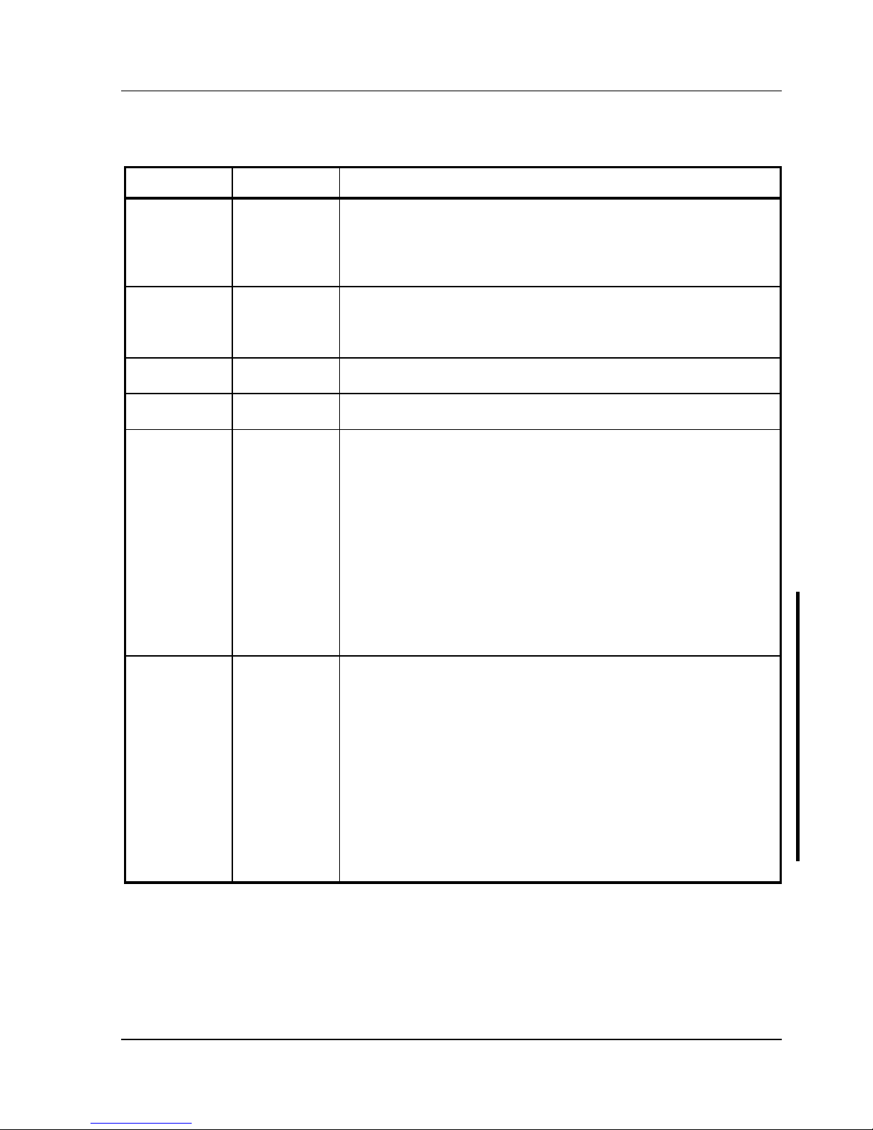
BIOS Setup Utility Options
Menu Field
Settings
Comments
System time
Current time Displays the current time.
System date
Current date Displays the current date.
ROM based
setup
Enabled
Disabled
Enables or disables the ROM base setup utility.
Note: If you select Disabled make sure the computer is bootable and
you have a working copy of SETUP.COM provided on the supplied
system and VGA utilities diskette.
Language
English
Français
Deutsch
Italiano
Español
Sets the desired language.
Note: You must exit the BIOS setup utility and reboot the computer to
get the setup screens to display the desired language.
Diskette A /
Diskette B
3.5", 1.44 MB
3.5", 2.88 MB
Not Installed
5.25", 360 KB
5.25", 1.2 MB
3.5", 720 KB
Sets the size and density of diskette drives.
Hard disk 1 /
hard disk 2
Drive types 1
through 49
Enables hard drive size and specific parameters from a predetermined
list of drive types. Drive types 2 and 3 or 48 and 49 are user definable
for hard drives not listed in the BIOS drive table.
Caution: It is essential to specify the correct IDE hard disk type
because the main logic board’s BIOS cannot independently verify this
information. The BIOS will not recognize the installed IDE hard disk
if the drive type is incorrect.
Note: Choose types 48 and 49, unless there is a conflict with the
network; in that case select types 2 and 3. If you select types 2 and 3
make sure to shadow the main board’s BIOS.
Note: If the primary bootable device is a SCSI device, set both hard
disk options to NOT INSTALLED.
Base memory
640 KB Displays the size of base (conventional) memory.
Note: The main logic board reserves the first 1024 KB of address
space for computer use. Base memory (640 KB) is first assigned to
the operating system. The remaining 384 KB is assigned to shadow
main logic board BIOS, video BIOS, or for other computer use.
Base memory is always 640 KB unless an error is detected. If an error
is detected, the BIOS Setup utility determines the actual memory
found (base and extended) and places the values in their respective
fields.
Extended
memory
Not user
selectable
Displays the current amount of extended memory.
Digital DECpc LP Utilities & Configuration
MCS Logistics Engineering - Nijmegen 19
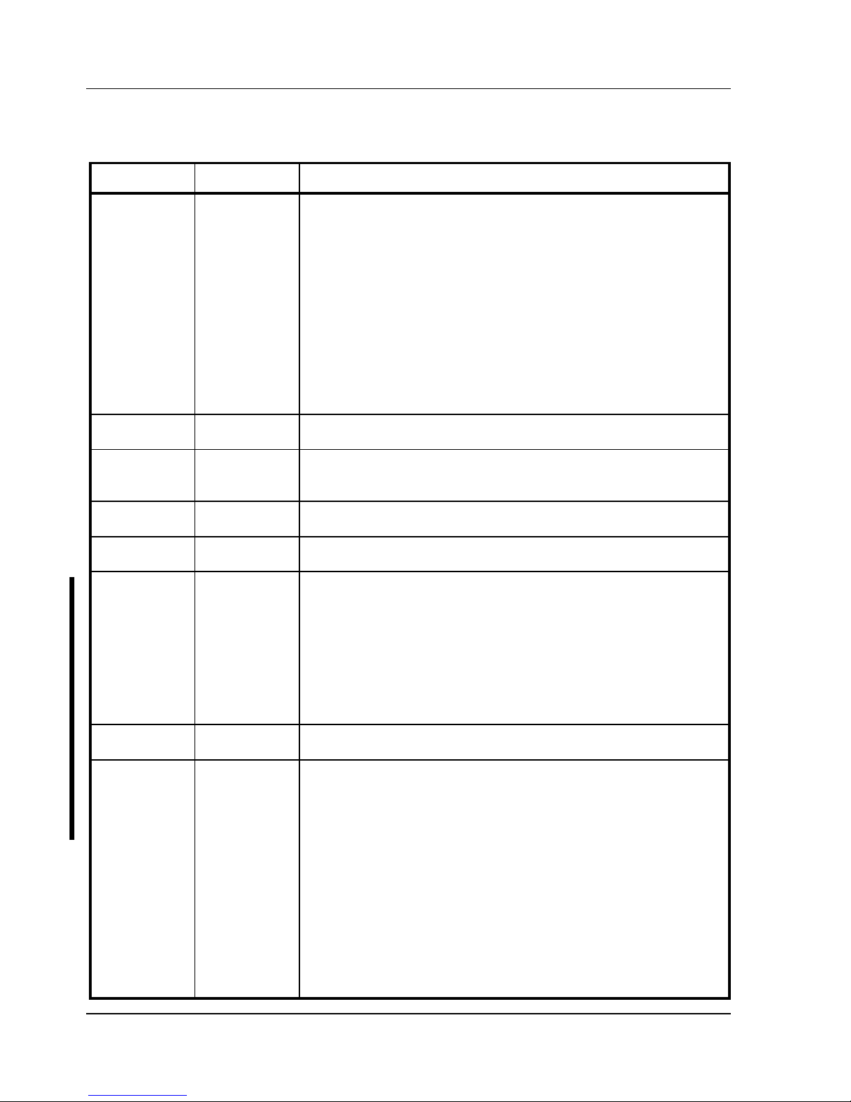
BIOS Setup Utility Options (continued)
Menu Field
Settings
Comments
Video card
VGA or EGA
CGA 40 Col
CGA 80 Col
Monochrome
Not Installed
Sets the video controller type.
Keyboard
Installed
Not Installed
Enables or disables the keyboard when using the computer as a
network server.
Note: The computer must initially be set up with a keyboard.
NumLock on
boot
On
Off
Enables or disables the NumLock feature each time the computer
boots.
Password
Not Installed
Installed
Enables or disables a power-on password.
Parallel port
Enabled at:
378h-37Ah
(IRQ7)
278h-27Ah
(IRQ7)
3BCh-3BEh
(IRQ7)
Disabled
Bi-directional
mode
Compatible
mode
Enables or disables any desired onboard printer port at the specified
address.
Allows to select between standard printer and bi-directional
applications.
Serial port 1
Enabled as
COM1: 3F8h 3FFh (IRQ4)
Enabled as
COM2: 2F8h 2FFh (IRQ3)
Enabled as
COM3: 3E8h 3EFh (IRQ4)
Enabled as
COM4: 2E8h 2EFh (IRQ3)
Disabled
Enables or disables any desired onboard serial port at the specified
address.
Utilities & Configuration Digital DECpc LP
20 MCS Logistics Engineering - Nijmegen
BIOS Setup Utility Options (continued)
Menu Field
Settings
Comments
Serial port 2
Enabled as
COM2: 2F8h 2FFh (IRQ3)
Enabled as
COM3: 3E8h 3EFh (IRQ4)
Enabled as
COM4: 2E8h 2EFh (IRQ3)
Enabled as
COM1: 3F8h 3FFh (IRQ4)
Disabled
Enables or disables any desired onboard serial port at the specified
address.
Diskette drive
Enabled
Disabled
Enables or disables the onboard diskette drive controller.
IDE hard disk
drives
Enabled
Disabled
Enables or disables the onboard IDE disk drive controller.
Disable this option when having a SCSI controller installed in one of
the expansion slots.
Boot from
diskette A
Enabled
Disabled
Enables or disables drive A as the logical boot device.
Boot from
hard disk C
Enabled
Disabled
Enables or disables drive C as the logical boot device.
HDD user
definable
types
Types 2 and 3
Types 48 and
49
The BIOS Setup utility allows types 2 and 3 or types 48 and 49 to be
user definable.
Drive type 48 or 49 information is aliased to drive type 2 or 3 when
application software does not recognize drive types above 47.
Auto-detection of IDE drive parameter is supported in types 2 and 3
and types 48 and 49.
Some operating systems do not recognize hard disk drive types above
29. Auto-detection of IDE drive parameter is supported in types 2 and
3 and types 48 and 49.
Exchange
diskette drives
Disabled
Enabled
Allows to logically exchange physical diskette drive designations.
CPU speed
Fast
Slow
Determines the speed used by the computer each time it is turned on
or rebooted.
Note: This option determines the speed used by the computer each
time it is turned on or rebooted.
Fast¾ is the normal speed and causes the CPU to run at its rated
speed.
Slow¾ (equivalent to 8 MHz) is used to reduce the effective CPU
speed to be compatible with some speed-dependent application
programs.
If an application program does not run correctly at full speed, try
disabling all caches or changing the CPU speed to slow.
Computer performance will be severely degraded while operating in
slow mode.
 Loading...