

Digital Equipment DECmpp 12000/Sx 100 Hardware Service Manual

DECmpp12000/SxModel100
HardwareServiceManual
Part Number: EK–DECAC–SM. C01
September 1992
This document provides service and diagnostic procedures for DECmpp
12000/Sx and DECmpp 12000–LC/Sx Series systems.
Revision/Update Information: This document has been revised for
DECmpp Version 1.1.
Operating System and Version: ULTRIX Version 4.2A.
Future releases may require higher
versions.
Software Version: DECmpp 12000/Sx Version 1.1.
Digital Equipment Corporation
Maynard, Massachusetts

First Printing, January 1992
Revised, September 1992
The information in this document is subject to change without notice and should not be construed
as a commitment by Digital Equipment Corporation. Digital Equipment Corporation assumes no
responsibility for any errors that may appear in this document.
The software described in this document is furnished under a license and may be used or copied
only in accordance with the terms of such license.
NOTICE—Class A Computing Device:
This equipment generates, uses, and may emit radio frequency energy. The equipment has been
type tested and found to comply with the limits for a Class A computing device pursuant to Subpart
J or Part 15 of FCC rules, which are designed to provide reasonable protection against such radio
frequency interference when operated in a commercial environment. Operation of this equipment in
a residential area may cause interference; in which case, measures taken to correct the interference
are at the user’s expense.
Restricted Rights: Use, duplication, or disclosure by the U.S. Government is subject to restrictions
as set forth in subparagraph (c)(1)(ii) of the Rights in Technical Data and Computer Software
clause at DFARS 252.227-7013.
© Digital Equipment Corporation 1992.
All Rights Reserved.
The postpaid Reader’s Comments forms at the end of this document request your critical evaluation
to assist in preparing future documentation.
The following are trademarks of Digital Equipment Corporation: DECnet, DECstation, DECsupport,
DECsystem, DECwindows, Rdb/VMS, ThinWire, TURBOchannel, ULTRIX, VAX, VAX DOCUMENT,
VMS, and the DIGITAL logo.
The following are registered trademarks of the MasPar Computer Corporation: MasPar and
the MasPar logo. The following are trademarks of the MasPar Computer Corporation: MasPar
Data Display Library (MPDDL), MasPar FORTRAN (MPF), MasPar Input/Output Channel,
MasPar Parallel Application Language (MPL), MasPar Parallel Disk Array (MPDA), and MasPar
Programming Environment (MPPE). UNIX is a registered trademark of UNIX System Laboratories,
Inc.
This document was prepared using VAX DOCUMENT, Version 2.0.

Contents
Preface ............................................................ vii
1 System Overview
1.1 Turning the System On and Off . ................................ 1–4
1.1.1 Powerup Sequence ........................................ 1–6
1.1.2 Powerdown Sequence ...................................... 1–6
2 DPU Controls and Indicators
2.1 Overview of Controls and Indicators ............................. 2–5
2.2 DPU Power System . . ........................................ 2–5
2.3 Indicators . . ................................................ 2–7
2.3.1 Front Panel Indicators ..................................... 2–7
2.3.2 Service Indicators ........................................ 2–7
2.3.2.1 Power Tray Indicators . . ................................ 2–9
2.3.2.2 Array Control Unit PCB Indicators . ....................... 2–10
2.3.2.3 PE Array and Router PCB Indicators ...................... 2–12
2.3.2.4 PVME Indicators ...................................... 2–13
3 Checking and Adjusting DPU Power Supply
3.1 Voltage Measurements and Adjustments . . . ....................... 3–3
4 Cables, Connectors, and Auxiliary PCBs
4.1 Cables and Connectors ........................................ 4–1
4.2 Auxiliary PCBs ............................................. 4–2
5 Using Diagnostic Software
5.1 Diagnostic Environment....................................... 5–2
5.1.1 Running the Diagnostics . . . ................................ 5–2
5.1.2 Suspending a Diagnostic Program ............................ 5–2
5.2 Types of Tests............................................... 5–3
5.2.1 Test Suites .............................................. 5–3
5.2.1.1 The acu_diag Test Suite . ................................ 5–3
5.2.1.2 The pe_diag Test Suite . . ................................ 5–3
5.2.2 Test Descriptions . ........................................ 5–4
5.3 Interpreting Log File Messages . ................................ 5–7
5.3.1 The ./LOG File . . . ........................................ 5–8
5.3.2 The /usr/adm/dpujobmgr.log File ............................. 5–10
5.3.3 The /etc/uerf File . ........................................ 5–12
iii

6 Removal and Replacement Procedures
6.1 Card Cage Access ............................................ 6–1
6.2 DPU Card Cage Slots......................................... 6–4
6.2.1 I/O Slots ................................................ 6–4
6.2.2 PE Array PCB Slots . . . .................................... 6–4
6.3 Replacing DPU Card Cage PCBs ................................ 6–6
6.3.1 Replacing the Array Control Unit PCB ........................ 6–6
6.3.2 Replacing Front-End VME Interface PCB . . . ................... 6–9
6.3.3 Replacing PE Array and Router PCBs ......................... 6–10
6.4 Replacing DPU Power Trays ................................... 6–11
6.4.1 Removing the DECmpp 12000/Sx Power Tray ................... 6–11
6.4.2 Installing the DECmpp 12000/Sx Power Tray ................... 6–13
6.4.3 Removing the DECmpp 12000–LC/Sx Power Tray ................ 6–14
6.4.4 Installing the DECmpp 12000–LC/Sx Power Tray ................ 6–15
6.5 Replacing the DECmpp 12000/Sx DPU Fan Tray. ................... 6–18
6.6 Replacing the DECmpp 12000–LC/Sx DPU Fan Tray ................ 6–19
6.7 Removing and Replacing the Lightpipe PCB ....................... 6–20
6.7.1 DECmpp 12000/Sx Lightpipe ................................ 6–20
6.7.2 DECmpp 12000–LC/Sx Lightpipe. ............................ 6–21
7 Backplane Jumpers and Upgrading PE Arrays
7.1 DPU Backplane Jumpers . . .................................... 7–1
7.1.1 Backplane Access ......................................... 7–3
7.1.2 ACU, VMEbus, and I/O Jumpers . ............................ 7–4
7.1.3 X-Net Jumpers ........................................... 7–5
7.2 System Issues for Upgrades .................................... 7–7
7.3 Adding Processor Element Array PCBs ........................... 7–8
7.4 Reconfiguring Processor Element Array PCBs . . . ................... 7–9
A Recommended Spares List
B Data Parallel Unit Reference Pages
acu_ppdma(1) . . . ............................................ B–2
mpconfig(1)................................................. B–3
mpi(1). .................................................... B–4
mpq(1) .................................................... B–5
mpstat(1) .................................................. B–6
pe_arith(1) ................................................. B–8
pe_ckonet(1) ................................................ B–9
pe_diag(1).................................................. B–10
pe_func(1).................................................. B–12
pe_macro(1) ................................................ B–13
pe_memdiag(1) . . ............................................ B–59
pe_rtbp(1).................................................. B–60
pe_rtdiag(1) ................................................ B–62
pe_rtr(1) ................................................... B–63
pe_scan(1) ................................................. B–64
dpumanager(8) . . ............................................ B–65
mpshutdown(8) . ............................................ B–68
iv

Index
Figures
1–1 Typical DECmpp 12000/Sx Installation with DECsystem 5900
Server . ................................................ 1–2
1–2 Typical DECmpp 12000/Sx Installation with DECstation 5000/240
Server . ................................................ 1–2
1–3 Typical DECmpp 12000–LC/Sx Installation ..................... 1–3
1–4 DECsystem 5900 Power Switch .............................. 1–5
1–5 DECstation 5000 Power Switch .............................. 1–5
2–1 DECmpp 12000/Sx DPU Front Controls and Indicators ............ 2–2
2–2 DECmpp 12000-LC/Sx DPU Front Controls and Indicators . . ....... 2–3
2–3 DPU Front Controls ....................................... 2–3
2–4 DPU Rear Controls and Indicators ........................... 2–4
2–5 PCB Service Indicator Locations ............................. 2–8
2–6 Power Tray Service Indicators ............................... 2–9
2–7 Array Control Unit PCB Indicators ........................... 2–10
2–8 PE and Router PCB Indicators .............................. 2–12
2–9 PVME Signal Indicators.................................... 2–13
3–1 DPU Backplane Voltage Test Points ........................... 3–2
3–2 DECmpp 12000 Power Supply Wiring and Voltage Adjustments .... 3–4
3–3 DECmpp 12000–LC HC Power Supply and Voltage Adjustments .... 3–5
3–4 DECmpp 12000–LC Powertec Power Supply and Voltage Adjustments
....................................................... 3–5
4–1 DPU-Server Cables ....................................... 4–2
6–1 DECmpp 12000/Sx Card Cage Access . . ....................... 6–2
6–2 DECmpp 12000–LC/Sx Card Cage Access ...................... 6–3
6–3 DPU Card Cage Slots...................................... 6–5
6–4 PCB Ejector Levers ....................................... 6–7
6–5 ACU Jumpers . . . ........................................ 6–8
6–6 DECmpp 12000 DPU Power Tray Rear . ....................... 6–12
6–7 DECmpp 12000 DPU Power Tray Front ....................... 6–12
6–8 Powertec Power Supply .................................... 6–16
6–9 HC Power Supply. ........................................ 6–17
6–10 Removing the DECmpp 12000–LC Enclosure Top . ............... 6–22
6–11 Replacing the Lightpipe PCB ................................ 6–22
7–1 DPU Card Cage Slots...................................... 7–2
7–2 DECmpp 12000–LC/Sx Front Doors ........................... 7–3
7–3 DPU Backplane Jumpers . . . ................................ 7–4
7–4 DECmpp 12000–LC/Sx X-Net Jumper Configurations ............. 7–5
7–5 DECmpp 12000/Sx X-Net Jumper Configurations . ............... 7–6
v

Tables
1 Related Documents . . . .................................... viii
1–1 DPU Power Settings . . .................................... 1–4
2–1 Front Panel Indicators . .................................... 2–7
2–2 Power Tray Service Indicators . . . ............................ 2–9
2–3 ACU Indicators .......................................... 2–11
2–4 PE Array and Router Indicators . ............................ 2–12
2–5 PVME Indicator Descriptions................................ 2–14
5–1 FLTCOD Values .......................................... 5–7
6–1 ACU Jumper Settings . .................................... 6–8
6–2 Powertec Power Supply Wiring . . ............................ 6–16
6–3 HC Power Supply Wiring ................................... 6–17
A–1 DECmpp 12000/Sx Data Parallel Unit RSL . . ................... A–1
vi

This manual provides service and diagnostic procedures for DECmpp 12000/Sx
systems. Anyone who services DECmpp 12000/Sx Series systems or needs to
replace any items should read this manual and be familiar with the procedures.
Intended Audience
This guide is for use by Digital Services personnel and by self-maintenance
customers who will be servicing the DECmpp 12000 and DECmpp 12000–LC
systems.
Document Structure
The DECmpp 12000/Sx Hardware Service Manual contains seven chapters and
two appendixes.
• Chapter 1 is a system overview and contains the power-up and power-down
routines for both the data parallel unit (DPU) and the front-end server.
• Chapter 2 describes the DPU switches, controls, indicators, and the DPU
power system.
• Chapter 3 describes the DPU power supply settings and how to adjust them,
if necessary.
Preface
• Chapter 4 describes the DECmpp 12000/Sx system cables, connectors, and the
printed circuit boards (PCBs) outside the DPU card cage.
• Chapter 5 describes the diagnostic software provided, how to use it, and how
to interpret the results.
• Chapter 6 explains the procedures for removing and replacing the DPU
components.
• Chapter 7 explains the procedures for upgrading the DECmpp 12000/Sx
Series systems by adding more processor element (PE) array PCBs.
• Appendix A lists all of the recommended spare parts for the DPU.
• Appendix B is a collection of Reference Pages that apply to the DPU.
vii

Related Documents
Table 1 lists documents that provide additional information about the DECmpp
12000/Sx system.
Table 1 Related Documents
Document Title Order Number
DECmpp 12000/Sx System Overview Manual AA-PMAPB-TE
DECmpp 12000/Sx System Administration Guide AA-PKU3C-TE
DECmpp 12000/Sx Architecture Specification AA-PMASB-TE
DECmpp 12000/Sx Parallel Disk Array Reference Manual EK-DECAB-RM
DECmpp 12000/Sx Parallel VME Reference Manual EK-DECAB-PM
DECmpp 12000/Sx Hardware Installation Guide EK-DECAC-IG
DECstation 5000/240 User Documentation Kit EK-PM380-DK
DECstation 5000/240 Maintenance Guide EK-PM38C-MG
DECstation 5000/240 Pocket Service Guide EK-PM38D-PG
DECsystem 5900 Site Preparation Guide EK-D590A-SP
DECsystem 5900 Installation Guide EK-D590A-IN
DECsystem 5900 Owner’s Guide EK-D590A-OG
DECsystem 5900 Pocket Service Guide EK-D590A-PS
DECsystem 5900 Enclosure Maintenance Manual EK-D590A-EN
DWTVX-Ax VME I/O Subsystem Pocket Service Guide EK-DWTVX-PS
T6000 Module Installation/Owner’s Card EK-T6000-IN
viii

Conventions
The following conventions are used throughout the DECmpp 12000/Sx
documentation set:
Convention Meaning
Return
Ctrl/x A key combination, shown with a slash separating the two key
MB1, MB2, MB3 The buttons on a mouse. MB1 is the left button, MB2 is the
% A percent sign (%) represents the default user prompt for your
# A number sign (#) represents the default superuser (root)
...
.
.
.
[] In syntax descriptions and functional descriptions, brackets
dpumanager(6)
italicized text In examples, italicized text denotes parameters, values, or
ULTRIX keywords
Code examples
UPPERCASE and
lowercase strings
In examples, a key name shown within a box indicates that
you press a key on the keyboard. In text, a key name is not
enclosed in a box but is printed with an initial capital letter,
like Return.
names, indicates that you hold down the first key while you
press the second key.
center button, and MB3 is the right button of a mouse whose
button arrangement is right-handed. It is possible to redefine
the mouse buttons.
system.
prompt for your system.
In examples, a horizontal series of dots, or ellipsis, indicates
that additional parameters, values, or other information can be
entered.
In examples, a vertical series of dots, or vertical ellipsis,
indicates that a portion of the example is intentionally omitted.
indicate optional items.
Cross-references to the ULTRIX Reference Pages, which include
the appropriate section number in parentheses.
other information that will change from either session to
session or user to user. In text, italicized words or phrases are
used to add emphasis to important words, concepts, or titles of
manuals.
This typeface is used to indicate system output or the exact
name of a command, option, partition, pathname, directory, or
file.
This typeface is used to display program coding examples.
The ULTRIX system differentiates between lowercase and
uppercase characters. Literal strings that appear in text,
examples, syntax descriptions, and function descriptions must
be entered exactly as shown.
ix

Both the DECmpp 12000/Sx and DECmpp 12000–LC/Sx Series hardware systems
are described in this manual. However, because the two systems are very similar,
references to the DECmpp 12000 system also apply to the DECmpp 12000–LC
system, unless specific differences between the two systems are noted.
Three types of notes are used in this manual:
• Note
Gives additional information or information particularly important to the
procedure.
• Caution
Indicates potential damage to equipment or data.
• Warning
Indicates potential injury to a person.
x

1
System Overview
DECmpp 12000/Sx Series systems are powerful single-instruction, multiple data
(SIMD) computers, consisting of a data parallel unit (DPU), which performs
the parallel calculations, and a front-end server. The server runs the ULTRIX
operating system and functions as a scalar processor. A high-speed VMEbus
interface carries data between the DPU and the front-end server.
The DPU contains the array control unit (ACU) PCB and from 1 to 16 processor
element (PE) array PCBs. The ACU controls the PE arrays, which perform the
parallel calculations. Each PE array PCB provides 1024 processor elements. The
total collection of PE array PCBs in a system comprise the PE array.
DECmpp 12000 systems support 1, 2, 4, 8, or 16 PE array PCBs and have 15
I/O slots for optional I/O PCBs. The DPU is housed within an H9A00 series
enclosure. DECmpp 12000 systems may be ordered with either a DECsystem
5900 server or a DECstation 5000/240 server. The DECsystem 5900 is contained
within a separate H9A00 series enclosure. This configuration is illustrated in
Figure 1–1. The DECstation 5000/240 and its storage devices are contained
within two desktop boxes. This configuration is illustrated in Figure 1–2.
DECmpp 12000–LC systems support 1, 2, or 4 PE array PCBs and have 5 I/O
slots for optional I/O PCBs. The DPU is contained within a low profile cabinet
and connects to a table-top DECstation 5000 server (Figure 1–3).
Any of the DECmpp 12000/Sx/Sx system configurations may also contain an
optional Parallel Disk Array (PDA). The PDA subsystem is housed in a separate
H9A00 series enclosure.
System Overview 1–1

Figure 1–1 Typical DECmpp 12000/Sx Installation with DECsystem 5900 Server
Parallel Disk Array
DECsystem 5900 Server Data Parallel Unit
DECmpp 12000 Sx Series
Console
Monitor
(Optional)
MKV−040000314−19−RAGS
Figure 1–2 Typical DECmpp 12000/Sx Installation with DECstation 5000/240 Server
Parallel Disk Array
(Optional)
DECstation 5000/240
Server
Data Parallel Unit
1–2 System Overview
MKV−040000314−46−RAGS
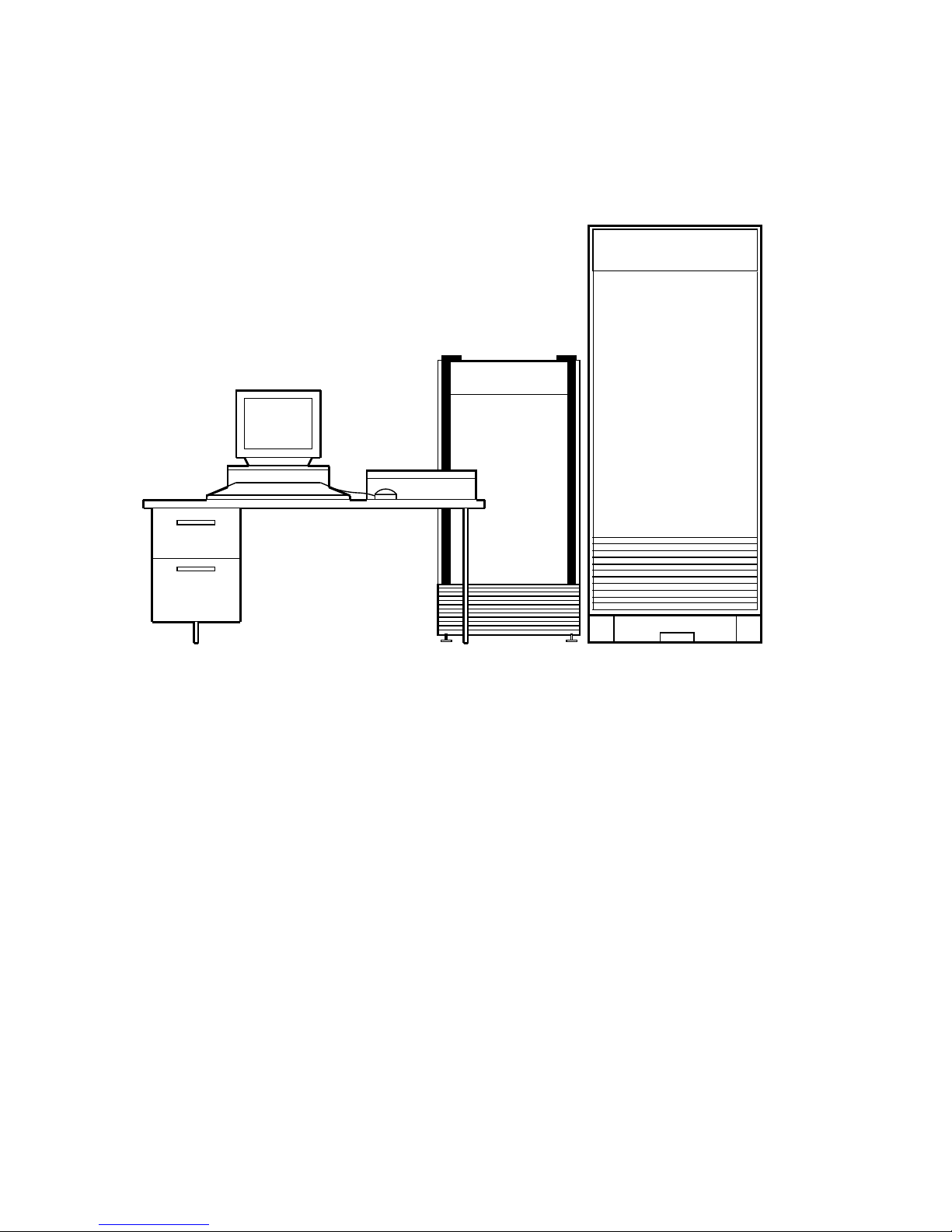
Figure 1–3 Typical DECmpp 12000–LC/Sx Installation
Data Parallel Unit
DECstation 5000/240
Server
DECmpp 12000
Parallel Disk Array
(Optional)
MKV−040000314−23−RAGS
System Overview 1–3

1.1 Turning the System On and Off
1.1 Turning the System On and Off
The DPU has three switches that control power: the keyswitch, the power
selector, and the circuit breaker. Figure 2–1, Figure 2–2, and Figure 2–4 show
their locations. Chapter 2 provides details on these switches.
The DPU keyswitch inside the front door has three positions: OFF, ON, and
DIAGNOSTIC:
• OFF turns DPU power off.
• ON turns DPU power on.
• DIAGNOSTIC is similar to ON, but it also enables the VMEbus RESET
button.
The DPU power selector switch has three positions: REMOTE, LOCAL, and
OVERRIDE:
• REMOTE (lower position): Not used.
• LOCAL (middle position): Turns on the DPU independently of the server.
• OVERRIDE (straight up): Turns on the DPU, regardless of other conditions.
Warning
Do not use the OVERRIDE setting. It overrides critical safety
systems. The OVERRIDE setting is for factory use only.
Table 1–1 shows the relationships between the DPU keyswitch and the DPU
power selector.
Table 1–1 DPU Power Settings
DPU Power Selector DPU Keyswitch DPU Power
REMOTE N/A N/A
LOCAL OFF OFF
LOCAL ON/DIAGNOSTIC ON
OVERRIDE Any setting ON (Factory Use Only)
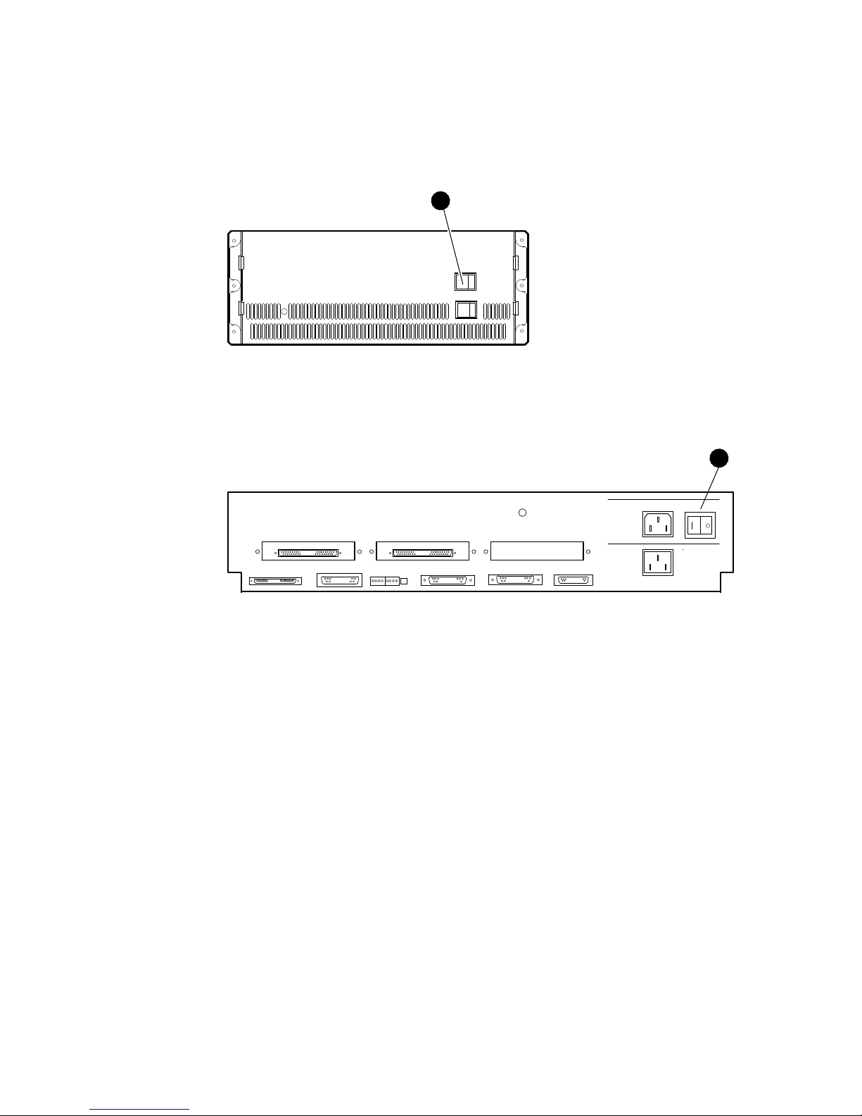
The power switch for the DECsystem 5900 server is on the front of the CPU
drawer. It is labeled!in Figure 1–4. The power switch for the DECstation 5000
server is at the rear of the CPU box. It is labeled!in Figure 1–5. Both are
rocker switches, labeled O and |. The server is ON when the | is pushed in.
1–4 System Overview
1.1 Turning the System On and Off
Figure 1–4 DECsystem 5900 Power Switch
1
MKV-040000314-36-DG
Figure 1–5 DECstation 5000 Power Switch
1
MKV-040000314-50-DG
System Overview 1–5

1.1 Turning the System On and Off
1.1.1 Powerup Sequence
To avoid unpredictable system operation, always turn the system
components on or off in the correct sequence.
Take these steps to power up the DECmpp 12000/Sx:
1. Set the DPU rear circuit breaker to ON.
2. Turn on the DPU, setting the keyswitch to ON.
3. Turn on the Parallel Disk Array (PDA), if present in the configuration, by
setting the rear circuit breaker to ON.
4. Turn on the server.
5. Boot the server.
When the system boots, it is ready to operate.
If you boot the server before you turn on the DPU, you cannot access the DPU.
Any time you reconnect or cycle DPU power down and up, you must reboot the
server.
Caution
1.1.2 Powerdown Sequence
Take these steps to power down the DECmpp 12000/Sx:
1. Halt the server, using either the
2. Turn off the PDA, if present in the configuration, by setting the rear circuit
breaker to OFF.
3. Turn off the DPU, setting the keyswitch to OFF.
4. Set the DPU rear circuit breaker to OFF.
5. Turn off the server.
Always set the circuit breaker at the rear of the DPU to OFF and unplug
the power cord when working on the power supply or power system.
/etc/haltor/etc/shutdown
Warning
command.
1–6 System Overview

2
DPU Controls and Indicators
Chapter 2 provides descriptions and functional definitions of the data parallel
unit (DPU) controls. Indicators on both the outside and the inside of the DPU
show the status of the system and critical internal components.
Figure 2–1 (DECmpp 12000) and Figure 2–2 (DECmpp 12000–LC) show the
locations of the DPU front controls and indicators. To access the front controls
in either configuration, open the front door. The controls are located inside the
enclosure at the top. Figure 2–3 provides a detail of the front controls.
Figure 2–4 shows the location of the rear controls and indicators. The DPU
controls and indicators are described in detail in the following sections.
DPU Controls and Indicators 2–1

Figure 2–1 DECmpp 12000/Sx DPU Front Controls and Indicators
Power
19 18 17 16 15 14 13 12 11 10 09 08 07 06 05 04 03 02 01 00
Status Indicators
Front Controls
(Located Inside
Front Door)
2–2 DPU Controls and Indicators
MKV−040000314−58−RAGS
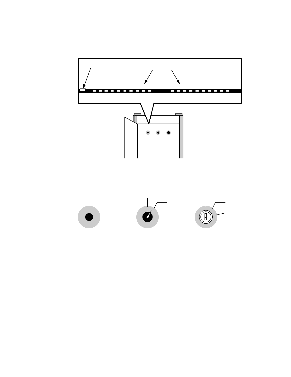
Figure 2–2 DECmpp 12000-LC/Sx DPU Front Controls and Indicators
Power
Figure 2–3 DPU Front Controls
Status Indicators
10111719 18 16 15 14 13 12 010709 08 06 05 04 03 02 00
MKV−040000314−52−RAGS
DISCONNECT
CONNECT
OFF
ON
RESET POWER
MODEM
DIAGNOSTIC
MKV−040000314−43−RAGS
DPU Controls and Indicators 2–3
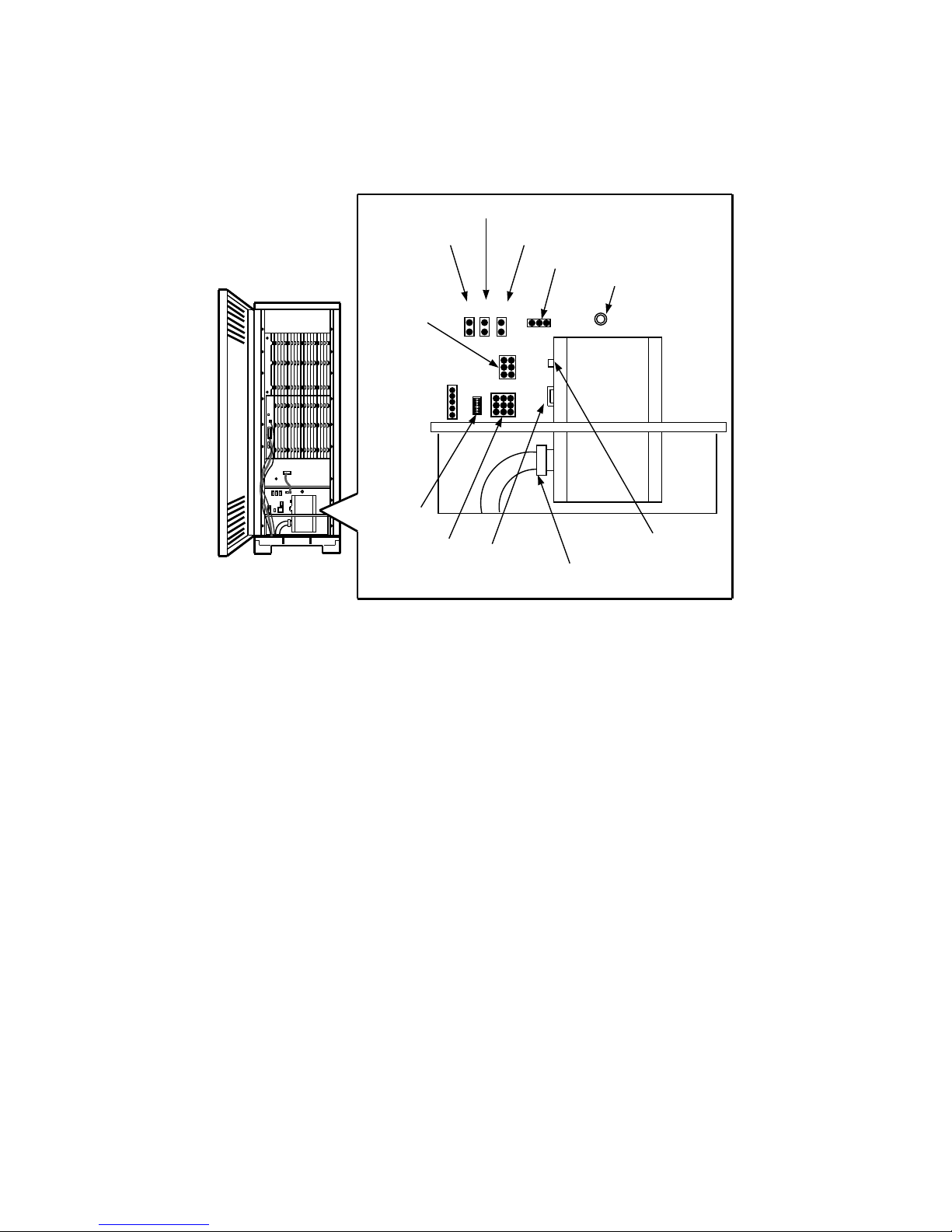
Figure 2–4 DPU Rear Controls and Indicators
Remote Daisy−chain
DPU Interface PCA
Modem
Power
LEDs
Backplane
Sense Lines
Lightpipe/
Key Switch
Temperature Sensor
P1 P2 P13
P3
P4
P10
30A Circuit
Breaker
Fan Tray
Power Cable
Connection
Power Selector
Switch
1A Circuit
Breaker
MKV−040000314−81−RAGS
2–4 DPU Controls and Indicators

2.1 Overview of Controls and Indicators
2.1 Overview of Controls and Indicators
Several of the DECmpp 12000/Sx controls and indicators are described briefly in
the list below. The rest are described in more detail in the following sections.
• POWER (keyswitch) — Controls power to the DPU and enables the VMEbus
RESET button.
• VMEbus RESET pushbutton — Pushing this button resets the VMEbus only
if the POWER keyswitch is set at DIAGNOSTIC.
• MODEM switch — At CONNECT, it enables the internal system modem
(USA only). At DISCONNECT, it disables the modem.
• POWER indicator — Provides information about the power supplies and fan
assembly, part of the front indicators.
• Power Selector — A three-position toggle switch, part of the rear controls.
• Service Indicators — Service indicators are described in detail in Section 2.3.
ACU Indicators — Provides information about the ACU PCB.
MVIB Indicator — Provides information about the Front-end VME
interface (T6000) PCB.
PVME Indicators — Provides information about the PVME PCB.
PE and Router PCB Indicators — Provides information about the PE
array and router.
2.2 DPU Power System
The DPU power system is complex, and you should understand it thoroughly
before changing any settings.
To avoid system problems, do not turn the DPU off before bringing the
front-end server to console or single-user mode.
The power system includes indicators that show the status of the various power
supplies and a power sequencer that ensures the power supplies start in the
correct order.
The DPU power system includes the following controls:
• The POWER keyswitch, shown in Figure 2–3, has three settings:
OFF (straight up) turns DPU power off.
ON (middle position) turns DPU power on when the power selector switch
is set to LOCAL.
Caution
DIAGNOSTIC (lower position) is similar to ON, but also enables the
VMEbus RESET button.
DPU Controls and Indicators 2–5

2.2 DPU Power System
• The POWER SELECTOR switch is on the power tray panel inside the DPU
enclosure at the rear. It is a toggle switch that must be pulled out slightly
before it can be moved. It has three positions.
LOCAL (middle position): Allows the DPU to power up independent of
the server.
OVERRIDE (straight up): Allows the DPU to power up regardless of
other conditions.
REMOTE (lower position): Not used.
• Two circuit breakers are on the outside rear of the DPU power tray and are
shown in Figure 2–4.
The rocker switch next to the power cable is a circuit breaker that is ON
when it is UP. The circuit breaker is rated at 30 A for the DECmpp 12000
and 15 A for the DECmpp 12000–LC. The amber lamp above the rocker
switch indicates there is power on both sides of the circuit breaker when
it is lit.
The small rocker-type breaker controls the current to the circuits
controlling the power sequencer. The amber lamp above the pushbutton
indicates that there is power on both sides of the breaker. The breaker
trips when it detects loads of more than 1 A. Push it in to reset it.
• The power status indicator on the DPU left front panel indicates the condition
of the power supplies.
Yellow during power supply ramp-up
Green when all DPU DC voltages are correct
When you first turn on the DPU, this indicator is yellow for approximately 3
seconds, then turns green. If it remains yellow, there is a power malfunction.
• A heat sensor shuts down all power supplies if it detects excess heat. The
power status indicator changes to yellow. After cooling, the power supplies
do not start again until the keyswitch is switched to OFF and then back to
ON or DIAGNOSTIC. An indicator on the power tray also indicates excess
temperature.
• When the DPU is turned on, the power sequencer turns on the -5 V power
supply and verifies its correct operation before turning on the +5 V power
supply. During this period (approximately 3 seconds), the power status
indicator is yellow. When the sequencer turns on the +5 V power supply, the
power status indicator turns green.
If the power status indicator remains yellow, the powerup sequencer did not
complete its sequence successfully. If this happens, switch the keyswitch to
OFF and then back to ON or DIAGNOSTIC.
2–6 DPU Controls and Indicators

2.3 Indicators
The DPU has indicators on the front panel, the ACU PCB, the MVIB Front-end
VME interface PCB (T6000), the PVME PVB, the PE array PCBs, the router
PCBs, and on the power tray. All of these indicators provide information about
the status of the system.
2.3.1 Front Panel Indicators
The DPU has 10 active indicators on the front panel, providing information about
the state of the DPU (Figure 2–1 or Figure 2–2). Most of these are two-color
indicators; they are either green, yellow, or off.
The front panel indicators are arranged in two banks of 10 indicators each.
Table 2–1 lists the front panel indicators, starting from the left.
Table 2–1 Front Panel Indicators
Label Green Yellow Off
Power Power, fan, and
19 System run light:
18 ACU is waiting for
17 ACU is waiting for
16 PMem is using PE PMem is not using PE
15 Router is active Not used No router activity
14 I/O is taking place
13 VME
12 VME
11 Not used VME parity error VME parity OK
10 Not used Normally always on Not used
23
9-0
temperature are OK
instructions are executing
TOBEQ
FRBEQ
between PEs and I/O
devices
AS
DT ACK
Not used Not used Not used
2.3 Indicators
System powering up
Macrocode is not running Not used
Not used ACU is not waiting
Page fault (overrides
green)
Machine is temporarily
stalled due to register
interlock
is active Not used VMEASis not
is active Not used VME
1
No AC power
present
for TOBEQ
ACU is not waiting
for FRBEQ
One or more PEs are
selected.
active
DT ACK
active
is not
1
During normal system powerup, the power status indicator is yellow for a few seconds, then changes
to green. If it remains yellow, the power sequencer did not complete powerup, and the power tray
indicators indicate the reason for failure. When the power sequencer stops trying to power up the
DPU, this indicator turns red.
2
Indicators 0-4 cycle when the software daemon is running.
3
Indicator 5 may become yellow if the background diagnostic tests fail.
2.3.2 Service Indicators
Service indicators include those on the various PCBs and on the power tray.
Figure 2–4 shows the location of the power tray service indicators. Figure 2–5
shows the location of the PCB service indicators.
DPU Controls and Indicators 2–7
2.3 Indicators
Figure 2–5 PCB Service Indicator Locations
PVME
Indicators
MVIB
Indicator
ACU
Indicators
Modem
(USA Only)
PE or Router PCBs (Shown with
4 PE PCBs and 12 Router PCBs)
PE and
Router Indicators
DECmpp 12000 Card Cage
MVIB
Indicator
Modem
(USA Only)
ACU
Indicators
PE and Router Indicators
(Shown with 4 PE PCBs)
DECmpp 12000−LC Card Cage
MKV−040000314−54−RAGS
2–8 DPU Controls and Indicators

2.3.2.1 Power Tray Indicators
Figure 2–6 shows the ten indicators located on the DPU power tray rear panel.
These indicators provide information about the power tray. They all show the
status of some part of the power tray and are green during normal operation. If
a failure is detected, the corresponding indicator changes to red, and the power
tray shuts down. Any red indicators are latched ON, indicating the problem area,
and initiate the power shutdown.
Figure 2–6 Power Tray Service Indicators
Chassis Ground
Temperature
Main Power Vcc +5 V
Main Power Vee −5 V
Main Power +12 V
Main Power −12 V
AUX Power Vcc +5 V
AUX Power Vee −5 V
AUX Power +12 V
AUX Power −12 V
2.3 Indicators
MKV−040000314−55−RAGS
Table 2–2 lists the function of each power tray indicator (from the top).
Table 2–2 Power Tray Service Indicators
PS Indicator Function
Chassis Ground Green — Normal
Temperature Green — Normal
Main Power Vcc +5 V Green — Normal
Main Power Vee –5 V ON — Normal
Main Power +12 V ON — Normal
Main Power –12 V ON — Normal
Auxiliary Power Vcc +5 V ON — 15 A or 30 A breaker is set ON
Auxiliary Power Vee –5 V ON — 15 A or 30 A breaker is set ON
Auxiliary Power +12 V ON — 15 A or 30 A breaker is set ON
Auxiliary Power –12 V ON — 15 A or 30 A breaker is set ON
Red — Logic ground to chassis ground short; excess voltage
detection
Red — Excess temperature
Red — Failure in +5 V supply
OFF — indicates problem with power sequencer
OFF — indicates problem with power sequencer
OFF — indicates problem with power sequencer
OFF — indicates problem with power sequencer
DPU Controls and Indicators 2–9

2.3 Indicators
The chassis ground circuit detects differences in potential between chassis ground
and logic ground and shuts down the power tray when the potential exceeds a
preset 70 mV threshold.
2.3.2.2 Array Control Unit PCB Indicators
Figure 2–5 shows indicator locations on the array control unit (ACU) PCB. The
12 indicators on the ACU PCB are arranged in three groups of four (Figure 2–7).
Table 2–3 lists the ACU indicator functions (from the top).
Figure 2–7 Array Control Unit PCB Indicators
Power
Bus Grant
Microcode Interrupt
Any_Reg
Data Strobe
Address Strobe
DTACK
IBUSY
BUSERR
MMSEL
Mempty
IFUVAL
MKV−040000314−56−RAGS
2–10 DPU Controls and Indicators

2.3 Indicators
Table 2–3 ACU Indicators
Indicator Function
Power ON when the ACU PCB is powered
Bus Grant ON when the ACU has VMEbus grant
Microcode
Interrupt
Any_Reg ON during a valid ACU access over the VMEbus
DSVME Data strobe
ASVME Address strobe
DTACK ACU is generating DTACK
IBUSY ACU is master of the bus
BUSERR When ON, a VMEbus transaction did not complete or completed with
MMSEL ON when the ACU is issuing current microcode from the M machine.
Mempty ON when there are no pending memory operations in the M machine
IFUVAL ON when the instruction fetch unit (IFU) is directed to a valid address.
ON when a microcode interrupt is in progress
an error. (An addressed VMEbus device did not respond within the
VMEbus timeout limit (approximately 60
signal in response to a VMEbus access.)
(The current operation is a memory access, not a PE calculation.)
Reasons for an invalid IFU access are:
sec) or returned an error
Attempting to execute code while a refresh cycle is in progress
A page fault
Attempting to execute code while the VMEbus is talking to
instruction memory
DPU Controls and Indicators 2–11

2.3 Indicators
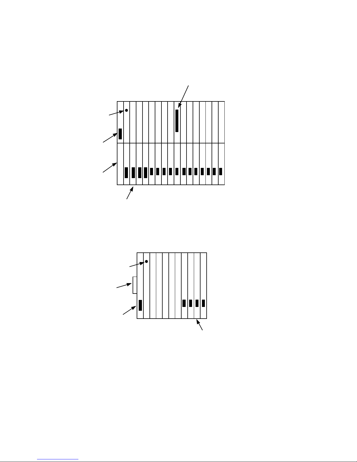
2.3.2.3 PE Array and Router PCB Indicators
Each PE array PCB has eight indicators arranged into two 4-LED groups. The
upper group provides status information about the PCB, and the lower bank
displays the results of the global OR (GOR) for that PCB. Router PCBs have
only the status indicators. Figure 2–5 shows the location of the PE and router
indicators in the DPU. Figure 2–8 shows the indicator pattern. Table 2–4 lists
the PE array and Router indicator functions (from the top).
Figure 2–8 PE and Router PCB Indicators
PE Array Router
Power
Parity Error
Selected for Diagnostics
GOR Enable
Power
Parity Error
Selected for Diagnostics
GOR Enable
GOR Bit 0
GOR Bit 1
GOR Bit 2
GOR Bit 3
MKV−040000314−57−RAGS
Table 2–4 PE Array and Router Indicators
Indicator Function
Power ON to indicate that the PCB is powered
Parity Error ON when a parity error occurs, and OFF when the error-handling
Selected for
Diagnostics
GOR Enable ON when the PCB GOR utility is selected
GOR Bit 0 ON when GOR bit 0 is active
GOR Bit 1 ON when GOR bit 1 is active
GOR Bit 2 ON when GOR bit 2 is active
GOR Bit 3 ON when GOR bit 3 is active
routine is completed or cleared by a reset
ON when the PCB is selected by a diagnostic routine
2–12 DPU Controls and Indicators
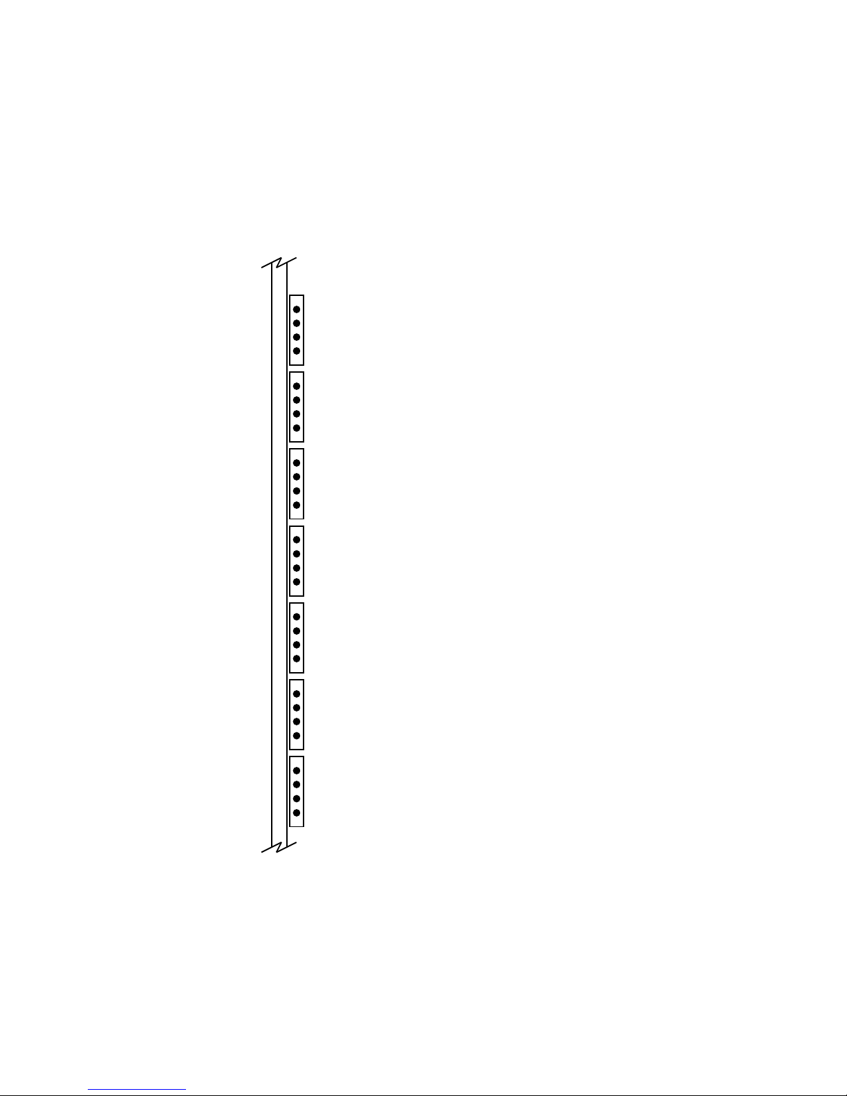
2.3.2.4 PVME Indicators
The PVME PCB has 28 signal indicators, as shown in Figure 2–9. Table 2–5 lists
the signal name and the signal abbreviation used on the PCB. When the indicator
is ON (green), the signal is true.
Figure 2–9 PVME Signal Indicators
2.3 Indicators
VCC
AS1
VDS
DAK
ACK
CYC
VAKI
VAKO
LBGI
LBGO
RBGI
RBGO
DMST
DBR
DBSY
DDAK
DXFR
STAL
ERR
QMTY
QFRZ
BWAT
BWRT
BREF
VGNT
CGNT
RGNT
BSLW
MKV−040000314−02−RAGS
DPU Controls and Indicators 2–13

2.3 Indicators
Table 2–5 PVME Indicator Descriptions
Signal Abbreviation Description
Vcc VCC ON: +5 V power supply is ON
AS1_ AS1 ON: VMEbus AS (address strobe) is true
vmeDS VDS ON: VMEbus DS (data strobe) is true
DTACK_ DAK ON: IOCTLR generated DTACK is true
bIACK ACK ON: VMEbus IACK (interrupt acknowledge) is true
IACKCYC CYC ON: IOCTLR is responding to an IACK VMEbus cycle
vmeIACKIN_ VAKI ON: VMEbus interrupt acknowledge daisy chain-in is true
vmeIACKOUT_ VAKO ON: VMEbus interrupt acknowledge daisy chain-out is true
vmeLBGIN_ LBGI ON: Local VMEbus grant daisy chain-in is true
dmaLBBGOUT_ LBGO ON: Local VMEbus grant daisy chain-out is true
vmeRBGIN_ RBGI ON: Remote VMEbus grant daisy chain-in is true
dmaRBGOUT_ RBGO ON: Remote VMEbus grant daisy chain-out is true
dmaMASTER DMST ON: IOCTLR is dma bus master
dmaBR_ DBR ON: IOCTLR is asserting request for VMEbus
dmaBBSY_ DBSY ON: IOCTLR is asserting VMEbus Busy
vmeDTACK_ DDAK ON: VMEbus DTACK is true
chDXFR_ DXFR N/A — May be ON or OFF (value is X)
chSTALL_ STAL N/A — May be ON or OFF (value is X)
chERR ERR N/A — May be ON or OFF (value is X)
queueEMPTY_ QMTY N/A — May be ON or OFF (value is X)
queueFROZ QFRZ N/A — May be ON or OFF (value is X)
babWAIT_ BWAT ON: IORAM is holding off access; address has crossed page boundary
babWRT_ BWRT ON: IORAM is performing a write cycle
refGNT_ BREF ON: IORAM is performing a refresh cycle
vmeGRANT_ VGNT ON: VME Interface has been granted IORAM access
chGRANT_ CGNT N/A — May be ON or OFF (value is X)
rioGRANT_ RGNT ON: RIO Interface has been granted IORAM access
babSLOWDEV_ BSLW ON: Slow VME device has accessed IORAM
1
1
N/A = not applicable to PVME
2–14 DPU Controls and Indicators
 Loading...