

Digital Equipment DECmpp12000, SxModel100 Reference Manual

DECmpp12000/SxModel100
ParallelDiskArray
ReferenceManual
Part Number: EK–DECAB–RM. B01
September 1992
This document provides a complete description of the DECmpp 12000/Sx
Parallel Disk Array hardware, its installation and service procedures.
Revision/Update Information: This document has been revised for
DECmpp Version 1.1.
Operating System and Version: ULTRIX Version 4.2A.
Future releases may require higher
versions.
Software Version: DECmpp 12000/Sx Version 1.1.
Digital Equipment Corporation
Maynard, Massachusetts

First Printing, January 1992
Revised, September 1992
The information in this document is subject to change without notice and should not be construed
as a commitment by Digital Equipment Corporation. Digital Equipment Corporation assumes no
responsibility for any errors that may appear in this document.
The software described in this document is furnished under a license and may be used or copied
only in accordance with the terms of such license.
NOTICE—Class A Computing Device:
This equipment generates, uses, and may emit radio frequency energy. The equipment has been
type tested and found to comply with the limits for a Class A computing device pursuant to Subpart
J or Part 15 of FCC rules, which are designed to provide reasonable protection against such radio
frequency interference when operated in a commercial environment. Operation of this equipment in
a residential area may cause interference; in which case, measures taken to correct the interference
are at the user’s expense.
Restricted Rights: Use, duplication, or disclosure by the U.S. Government is subject to restrictions
as set forth in subparagraph (c) (1)(ii) of the Rights in Technical Data and Computer Software
clause at DFARS 252.227-7013.
© Digital Equipment Corporation 1992.
All Rights Reserved.
The postpaid Reader’s Comments forms at the end of this document request your critical evaluation
to assist in preparing future documentation.
The following are trademarks of Digital Equipment Corporation: DECnet, DECstation, DECsupport,
DECsystem, DECwindows, Rdb/VMS, ThinWire, TURBOchannel, ULTRIX, VAX, VAX DOCUMENT,
VMS, and the DIGITAL logo.
The following are registered trademarks of the MasPar Computer Corporation: MasPar and
the MasPar logo. The following are trademarks of the MasPar Computer Corporation: MasPar
Data Display Library (MPDDL), MasPar FORTRAN (MPF), MasPar Input/Output Channel,
MasPar Parallel Application Language (MPL), MasPar Parallel Disk Array (MPDA), and MasPar
Programming Environment (MPPE). UNIX is a registered trademark of UNIX System Laboratories,
Inc.
This document was prepared using VAX DOCUMENT, Version 2.0.

Contents
Preface . . . . . . . . . . . . . . . . . . . . . . . . . . . . . . . . . . . . . . . . . . . . . . . . . . . . . . . . . . . . ix
1 Parallel Disk Array Overview
1.1 Parallel Disk Array Components . . . . . . . . . . . . . . . . . . . . . . . . . . . . . . . . 1–5
1.1.1 Disk Array Controller . . . . . . . . . . . . . . . . . . . . . . . . . . . . . . . . . . . . . 1–6
1.1.2 DA Controller Backplane . . . . . . . . . . . . . . . . . . . . . . . . . . . . . . . . . . . 1–8
1.1.3 DA Backplane . . . . . . . . . . . . . . . . . . . . . . . . . . . . . . . . . . . . . . . . . . . 1–9
1.1.3.1 DA Controller Interconnect . . . . . . . . . . . . . . . . . . . . . . . . . . . . . . 1–11
1.1.3.2 Disk Canister Interconnect . . . . . . . . . . . . . . . . . . . . . . . . . . . . . . 1–11
1.1.3.3 Multiplexer Interconnect . . . . . . . . . . . . . . . . . . . . . . . . . . . . . . . . 1–11
1.1.3.4 Lightpipe Interconnect . . . . . . . . . . . . . . . . . . . . . . . . . . . . . . . . . . 1–11
1.1.3.5 Power Interconnect . . . . . . . . . . . . . . . . . . . . . . . . . . . . . . . . . . . . 1–11
1.2 Disk Chassis . . . . . . . . . . . . . . . . . . . . . . . . . . . . . . . . . . . . . . . . . . . . . . . 1–12
1.2.1 Disk Canisters . . . . . . . . . . . . . . . . . . . . . . . . . . . . . . . . . . . . . . . . . . . 1–12
1.2.2 MUX Printed Circuit Board . . . . . . . . . . . . . . . . . . . . . . . . . . . . . . . . . 1–13
1.2.2.1 Data Multiplexing . . . . . . . . . . . . . . . . . . . . . . . . . . . . . . . . . . . . . 1–13
1.2.2.2 Write Data . . . . . . . . . . . . . . . . . . . . . . . . . . . . . . . . . . . . . . . . . . . 1–13
1.2.2.3 Sector Pulse Monitor . . . . . . . . . . . . . . . . . . . . . . . . . . . . . . . . . . . 1–13
1.3 DPU-PDA Interface Cable . . . . . . . . . . . . . . . . . . . . . . . . . . . . . . . . . . . . . 1–13
1.4 Power/Fan Tray . . . . . . . . . . . . . . . . . . . . . . . . . . . . . . . . . . . . . . . . . . . . . 1–13
1.4.1 Power System . . . . . . . . . . . . . . . . . . . . . . . . . . . . . . . . . . . . . . . . . . . 1–15
1.4.2 Power/Fan Tray Indicators . . . . . . . . . . . . . . . . . . . . . . . . . . . . . . . . . . 1–16
1.4.3 Exhaust Fan . . . . . . . . . . . . . . . . . . . . . . . . . . . . . . . . . . . . . . . . . . . . 1–17
2 Parallel Disk Array Installation
2.1 Parallel Disk Array Site Preparation . . . . . . . . . . . . . . . . . . . . . . . . . . . . . 2–1
2.1.1 Physical Characteristics . . . . . . . . . . . . . . . . . . . . . . . . . . . . . . . . . . . . 2–1
2.1.1.1 Size and Service Clearance . . . . . . . . . . . . . . . . . . . . . . . . . . . . . . 2–1
2.1.1.2 Weight . . . . . . . . . . . . . . . . . . . . . . . . . . . . . . . . . . . . . . . . . . . . . . 2–1
2.1.2 Power and Cooling Requirements . . . . . . . . . . . . . . . . . . . . . . . . . . . . 2–1
2.1.3 Power and Environmental Specifications . . . . . . . . . . . . . . . . . . . . . . . 2–3
2.2 PDA Installation . . . . . . . . . . . . . . . . . . . . . . . . . . . . . . . . . . . . . . . . . . . . 2–4
2.2.1 Unpacking and Positioning the PDA . . . . . . . . . . . . . . . . . . . . . . . . . . 2–4
2.2.1.1 Assembling the Enclosure Skirts . . . . . . . . . . . . . . . . . . . . . . . . . . 2–6
2.2.2 Electrical Installation . . . . . . . . . . . . . . . . . . . . . . . . . . . . . . . . . . . . . 2–7
2.2.2.1 Printed Circuit Boards . . . . . . . . . . . . . . . . . . . . . . . . . . . . . . . . . . 2–7
2.2.2.2 Installing Disk Array Controller PCBs . . . . . . . . . . . . . . . . . . . . . 2–8
2.2.3 Installing MUX PCBs . . . . . . . . . . . . . . . . . . . . . . . . . . . . . . . . . . . . . 2–8
2.3 Installing Disk Canisters . . . . . . . . . . . . . . . . . . . . . . . . . . . . . . . . . . . . . . 2–8
2.3.1 Jumpers and Terminators . . . . . . . . . . . . . . . . . . . . . . . . . . . . . . . . . . 2–8
2.4 Connecting DPU and PDA . . . . . . . . . . . . . . . . . . . . . . . . . . . . . . . . . . . . . 2–11
2.4.1 Installing the DPU PCBs . . . . . . . . . . . . . . . . . . . . . . . . . . . . . . . . . . . 2–11
iii

2.5 Setting DPU Jumpers . . . . . . . . . . . . . . . . . . . . . . . . . . . . . . . . . . . . . . . . 2–15
2.6 Turning On the DPU and PDA . . . . . . . . . . . . . . . . . . . . . . . . . . . . . . . . . 2–17
3 Parallel Disk Array System Administration
3.1 Establishing PDA Communications . . . . . . . . . . . . . . . . . . . . . . . . . . . . . . 3–2
3.2 Controller Configuration . . . . . . . . . . . . . . . . . . . . . . . . . . . . . . . . . . . . . . 3–5
3.3 Setting Up File Systems . . . . . . . . . . . . . . . . . . . . . . . . . . . . . . . . . . . . . . 3–7
3.3.1 Default Partitions . . . . . . . . . . . . . . . . . . . . . . . . . . . . . . . . . . . . . . . . 3–7
3.4 Upgrade Procedures . . . . . . . . . . . . . . . . . . . . . . . . . . . . . . . . . . . . . . . . . . 3–8
3.4.1 Upgrading to 8 Disks . . . . . . . . . . . . . . . . . . . . . . . . . . . . . . . . . . . . . . 3–8
3.4.2 Upgrading to 16 Disks . . . . . . . . . . . . . . . . . . . . . . . . . . . . . . . . . . . . . 3–8
4 Disk Formatting
4.1 The FORMAT Command . . . . . . . . . . . . . . . . . . . . . . . . . . . . . . . . . . . . . . 4–1
4.1.1 Operation Examples . . . . . . . . . . . . . . . . . . . . . . . . . . . . . . . . . . . . . . . 4–3
4.1.1.1 Bring Up a New Bank . . . . . . . . . . . . . . . . . . . . . . . . . . . . . . . . . . 4–3
4.1.1.2 Bringing Up a New Bank with Flaw Data on Host . . . . . . . . . . . . 4–3
4.1.1.3 Formatting Newly Installed Disks Within an Online/Mounted
Bank . . . . . . . . . . . . . . . . . . . . . . . . . . . . . . . . . . . . . . . . . . . . . . . 4–3
4.1.1.4 Reformatting Online/Mounted Banks with Growth Errors
Logged . . . . . . . . . . . . . . . . . . . . . . . . . . . . . . . . . . . . . . . . . . . . . . 4–4
4.2 The MOUNTBANK Command . . . . . . . . . . . . . . . . . . . . . . . . . . . . . . . . . . 4–4
4.3 The RECONSTRUCT Command . . . . . . . . . . . . . . . . . . . . . . . . . . . . . . . . 4–5
4.3.1 Disabling and Replacing a Drive . . . . . . . . . . . . . . . . . . . . . . . . . . . . . 4–6
4.3.2 Assigning a Standby Drive . . . . . . . . . . . . . . . . . . . . . . . . . . . . . . . . . . 4–6
4.3.3 Reconstructing a Drive . . . . . . . . . . . . . . . . . . . . . . . . . . . . . . . . . . . . . 4–6
4.4 The SCRUB Command . . . . . . . . . . . . . . . . . . . . . . . . . . . . . . . . . . . . . . . . 4–8
4.5 The SPECIFYFLAW Command . . . . . . . . . . . . . . . . . . . . . . . . . . . . . . . . . 4–9
5 Removal and Replacement Procedures
5.1 Extending the DA Controller Chassis . . . . . . . . . . . . . . . . . . . . . . . . . . . . 5–3
5.2 Replacing DA Controller PCBs . . . . . . . . . . . . . . . . . . . . . . . . . . . . . . . . . . 5–5
5.3 Replacing Disk Canisters . . . . . . . . . . . . . . . . . . . . . . . . . . . . . . . . . . . . . . 5–6
5.4 Replacing MUX PCBs . . . . . . . . . . . . . . . . . . . . . . . . . . . . . . . . . . . . . . . . 5–7
5.5 Replacing the Lightpipe PCB . . . . . . . . . . . . . . . . . . . . . . . . . . . . . . . . . . . 5–8
5.6 Replacing Power/Fan Tray . . . . . . . . . . . . . . . . . . . . . . . . . . . . . . . . . . . . . 5–9
5.7 Replacing Power Cables to the DA Backplane . . . . . . . . . . . . . . . . . . . . . . 5–12
5.8 Replacing Clock PCB . . . . . . . . . . . . . . . . . . . . . . . . . . . . . . . . . . . . . . . . . 5–14
5.9 Replacing DA Controller Backplane Cabling . . . . . . . . . . . . . . . . . . . . . . . 5–15
5.9.1 Replacing PDA-DPU Interface Cable . . . . . . . . . . . . . . . . . . . . . . . . . . 5–15
5.9.2 Replacing Backplane Disk Cables . . . . . . . . . . . . . . . . . . . . . . . . . . . . 5–17
5.10 Replacing the Lightpipe Signal Cable . . . . . . . . . . . . . . . . . . . . . . . . . . . . 5–18
5.11 Replacing Lightpipe Power Cable . . . . . . . . . . . . . . . . . . . . . . . . . . . . . . . . 5–19
5.12 Replacing Temperature Sensor Cable . . . . . . . . . . . . . . . . . . . . . . . . . . . . . 5–20
iv

6 Parallel Disk Array Diagnostics
6.1 Lightpipe Indicator Status . . . . . . . . . . . . . . . . . . . . . . . . . . . . . . . . . . . . . 6–1
6.2 Diagnostic Procedures . . . . . . . . . . . . . . . . . . . . . . . . . . . . . . . . . . . . . . . . 6–3
6.3 Diagnostic Environment . . . . . . . . . . . . . . . . . . . . . . . . . . . . . . . . . . . . . . . 6–3
6.3.1 Automatic Mode . . . . . . . . . . . . . . . . . . . . . . . . . . . . . . . . . . . . . . . . . . 6–4
6.4 VME Adapter Tests . . . . . . . . . . . . . . . . . . . . . . . . . . . . . . . . . . . . . . . . . . 6–4
6.5 PDA Test Programs . . . . . . . . . . . . . . . . . . . . . . . . . . . . . . . . . . . . . . . . . . 6–4
6.5.1 Internal DA Controller Test (da_intern) . . . . . . . . . . . . . . . . . . . . . . . . 6–4
6.5.2 Read/Write Configuration Test (da_config) . . . . . . . . . . . . . . . . . . . . . . 6–4
6.5.3 Read/Write Buffer Test (da_buff) . . . . . . . . . . . . . . . . . . . . . . . . . . . . . 6–4
6.5.4 Mount Bank Test (da_mount) . . . . . . . . . . . . . . . . . . . . . . . . . . . . . . . . 6–4
6.5.5 Read/Seek Test (da_seek) . . . . . . . . . . . . . . . . . . . . . . . . . . . . . . . . . . . 6–5
6.5.6 Read/Write Disk Test (da_disk) . . . . . . . . . . . . . . . . . . . . . . . . . . . . . . 6–5
6.6 DA Controller Tests . . . . . . . . . . . . . . . . . . . . . . . . . . . . . . . . . . . . . . . . . . 6–5
6.7 Status Operations . . . . . . . . . . . . . . . . . . . . . . . . . . . . . . . . . . . . . . . . . . . 6–5
6.7.1 Disk Error Logging . . . . . . . . . . . . . . . . . . . . . . . . . . . . . . . . . . . . . . . 6–5
6.7.2 Error Information . . . . . . . . . . . . . . . . . . . . . . . . . . . . . . . . . . . . . . . . 6–7
6.7.3 Extended Transfer Error Status . . . . . . . . . . . . . . . . . . . . . . . . . . . . . . 6–9
6.7.4 Command/Status Summary . . . . . . . . . . . . . . . . . . . . . . . . . . . . . . . . . 6–10
7 Upgrading the Parallel Disk Array
7.1 Upgrading to Eight Disk Drives . . . . . . . . . . . . . . . . . . . . . . . . . . . . . . . . . 7–2
7.2 Upgrading to Sixteen Disk Drives . . . . . . . . . . . . . . . . . . . . . . . . . . . . . . . 7–3
A Configuration Data
A.1 The READCONFIG Command . . . . . . . . . . . . . . . . . . . . . . . . . . . . . . . . . . A–1
A.2 The WRITECONFIG Command . . . . . . . . . . . . . . . . . . . . . . . . . . . . . . . . . A–2
A.3 System Configuration Table . . . . . . . . . . . . . . . . . . . . . . . . . . . . . . . . . . . . A–3
A.3.1 Controller Configuration . . . . . . . . . . . . . . . . . . . . . . . . . . . . . . . . . . . A–4
A.3.2 Bank Control/Status Configuration . . . . . . . . . . . . . . . . . . . . . . . . . . . A–10
A.3.3 Disk Parameter Table Overview . . . . . . . . . . . . . . . . . . . . . . . . . . . . . A–15
A.3.4 Bad Block Table . . . . . . . . . . . . . . . . . . . . . . . . . . . . . . . . . . . . . . . . . . A–18
A.3.5 Bank X, Disk X, System Area Configuration . . . . . . . . . . . . . . . . . . . . A–19
A.3.6 System Area Home Page . . . . . . . . . . . . . . . . . . . . . . . . . . . . . . . . . . . A–20
A.3.7 System Area RFT and GET Pages . . . . . . . . . . . . . . . . . . . . . . . . . . . . A–21
B Parallel Disk Array System Block Diagrams
B.1 Parallel Disk Array System Block Diagrams . . . . . . . . . . . . . . . . . . . . . . . B–1
C Recommended Spares List
D Disk Array Variations and Options
v

E Parallel Disk Array Reference Pages
dabinit(8) . . . . . . . . . . . . . . . . . . . . . . . . . . . . . . . . . . . . . . . . . . . . . . . . . . E–2
dabstat(8) . . . . . . . . . . . . . . . . . . . . . . . . . . . . . . . . . . . . . . . . . . . . . . . . . . E–3
dadisk(8) . . . . . . . . . . . . . . . . . . . . . . . . . . . . . . . . . . . . . . . . . . . . . . . . . . E–4
dadsbl(8) . . . . . . . . . . . . . . . . . . . . . . . . . . . . . . . . . . . . . . . . . . . . . . . . . . E–5
daflaw(8) . . . . . . . . . . . . . . . . . . . . . . . . . . . . . . . . . . . . . . . . . . . . . . . . . . E–6
daformat(8) . . . . . . . . . . . . . . . . . . . . . . . . . . . . . . . . . . . . . . . . . . . . . . . . E–8
dainit(8) . . . . . . . . . . . . . . . . . . . . . . . . . . . . . . . . . . . . . . . . . . . . . . . . . . . E–10
damapchs(8) . . . . . . . . . . . . . . . . . . . . . . . . . . . . . . . . . . . . . . . . . . . . . . . . E–11
damount(8) . . . . . . . . . . . . . . . . . . . . . . . . . . . . . . . . . . . . . . . . . . . . . . . . . E–12
darecon(8) . . . . . . . . . . . . . . . . . . . . . . . . . . . . . . . . . . . . . . . . . . . . . . . . . E–13
dascrub(8) . . . . . . . . . . . . . . . . . . . . . . . . . . . . . . . . . . . . . . . . . . . . . . . . . E–14
daspecflaw(8) . . . . . . . . . . . . . . . . . . . . . . . . . . . . . . . . . . . . . . . . . . . . . . . E–16
dastat(8) . . . . . . . . . . . . . . . . . . . . . . . . . . . . . . . . . . . . . . . . . . . . . . . . . . . E–17
dasubs(8) . . . . . . . . . . . . . . . . . . . . . . . . . . . . . . . . . . . . . . . . . . . . . . . . . . E–18
daxformat(8). . . . . . . . . . . . . . . . . . . . . . . . . . . . . . . . . . . . . . . . . . . . . . . . E–19
daxrdc(8) . . . . . . . . . . . . . . . . . . . . . . . . . . . . . . . . . . . . . . . . . . . . . . . . . . E–20
daxscrub(8) . . . . . . . . . . . . . . . . . . . . . . . . . . . . . . . . . . . . . . . . . . . . . . . . E–21
daxwrc(8) . . . . . . . . . . . . . . . . . . . . . . . . . . . . . . . . . . . . . . . . . . . . . . . . . . E–22
da_error_log(8) . . . . . . . . . . . . . . . . . . . . . . . . . . . . . . . . . . . . . . . . . . . . . . E–23
da_error_report(8) . . . . . . . . . . . . . . . . . . . . . . . . . . . . . . . . . . . . . . . . . . . E–24
Index
Figures
1–1 DECmpp 12000/Sx Parallel Disk Array . . . . . . . . . . . . . . . . . . . . . . . . 1–2
1–2 Parallel Disk Array, Model SMP11-AA . . . . . . . . . . . . . . . . . . . . . . . . . 1–3
1–3 Parallel Disk Array, Model SMP11-AB . . . . . . . . . . . . . . . . . . . . . . . . . 1–4
1–4 Parallel Disk Array, Model SMP11-AC . . . . . . . . . . . . . . . . . . . . . . . . . 1–5
1–5 DA Controller Front Panel . . . . . . . . . . . . . . . . . . . . . . . . . . . . . . . . . . 1–6
1–6 DA Controller Slot Assignments . . . . . . . . . . . . . . . . . . . . . . . . . . . . . 1–7
1–7 DA Controller Backplane . . . . . . . . . . . . . . . . . . . . . . . . . . . . . . . . . . . 1–8
1–8 DA Drive Backplane (front) . . . . . . . . . . . . . . . . . . . . . . . . . . . . . . . . . 1–9
1–9 DA Drive Backplane (rear) . . . . . . . . . . . . . . . . . . . . . . . . . . . . . . . . . . 1–10
1–10 Disk Drive Canister . . . . . . . . . . . . . . . . . . . . . . . . . . . . . . . . . . . . . . . 1–12
1–11 Power/Fan Tray . . . . . . . . . . . . . . . . . . . . . . . . . . . . . . . . . . . . . . . . . . 1–14
1–12 Power Bridge and Cables . . . . . . . . . . . . . . . . . . . . . . . . . . . . . . . . . . . 1–16
1–13 Power/Fan Tray Service Indicators . . . . . . . . . . . . . . . . . . . . . . . . . . . 1–16
2–1 Parallel Disk Array Enclosure Dimensions . . . . . . . . . . . . . . . . . . . . . 2–2
2–2 Removing Enclosure Shipping Bracket . . . . . . . . . . . . . . . . . . . . . . . . 2–4
2–3 PDA Enclosure Levelers . . . . . . . . . . . . . . . . . . . . . . . . . . . . . . . . . . . . 2–5
2–4 Front and Side Skirts . . . . . . . . . . . . . . . . . . . . . . . . . . . . . . . . . . . . . 2–6
2–5 Rear Skirt . . . . . . . . . . . . . . . . . . . . . . . . . . . . . . . . . . . . . . . . . . . . . . 2–7
2–6 Disk Drive PCB (Component Side) . . . . . . . . . . . . . . . . . . . . . . . . . . . . 2–10
2–7 Inserting Disk Canister . . . . . . . . . . . . . . . . . . . . . . . . . . . . . . . . . . . . 2–11
vi

2–8 DPU Card Cage . . . . . . . . . . . . . . . . . . . . . . . . . . . . . . . . . . . . . . . . . . 2–12
2–9 DA Interface PCB Cable Connections . . . . . . . . . . . . . . . . . . . . . . . . . 2–13
2–10 Data Parallel Unit Card Cage Slots . . . . . . . . . . . . . . . . . . . . . . . . . . . 2–14
2–11 DPU Backplane Jumper Locations . . . . . . . . . . . . . . . . . . . . . . . . . . . . 2–16
5–1 PDA Enclosure (rear) . . . . . . . . . . . . . . . . . . . . . . . . . . . . . . . . . . . . . . 5–2
5–2 Extending the Disk Array Controller . . . . . . . . . . . . . . . . . . . . . . . . . . 5–4
5–3 Replacing the DA Controller PCB . . . . . . . . . . . . . . . . . . . . . . . . . . . . 5–5
5–4 Power/Fan Tray (rear) . . . . . . . . . . . . . . . . . . . . . . . . . . . . . . . . . . . . . 5–10
5–5 Replacing the Power/Fan Tray . . . . . . . . . . . . . . . . . . . . . . . . . . . . . . . 5–11
5–6 Power Bridge and Cables . . . . . . . . . . . . . . . . . . . . . . . . . . . . . . . . . . . 5–13
5–7 Replacing the Clock PCB . . . . . . . . . . . . . . . . . . . . . . . . . . . . . . . . . . . 5–14
6–1 PDA Front Indicators . . . . . . . . . . . . . . . . . . . . . . . . . . . . . . . . . . . . . . 6–2
B–1 Full System Block Diagram . . . . . . . . . . . . . . . . . . . . . . . . . . . . . . . . . B–1
B–2 Disk Array Controller Block Diagram . . . . . . . . . . . . . . . . . . . . . . . . . B–2
B–3 Disk Array Backplane Block Diagram . . . . . . . . . . . . . . . . . . . . . . . . . B–2
Tables
1 Related Documents . . . . . . . . . . . . . . . . . . . . . . . . . . . . . . . . . . . . . . . x
1–1 PDA Configurations . . . . . . . . . . . . . . . . . . . . . . . . . . . . . . . . . . . . . . . 1–2
1–2 DA Backplane Connectors . . . . . . . . . . . . . . . . . . . . . . . . . . . . . . . . . . 1–10
1–3 Power System Capabilities . . . . . . . . . . . . . . . . . . . . . . . . . . . . . . . . . . 1–15
1–4 Backplane Power Requirements . . . . . . . . . . . . . . . . . . . . . . . . . . . . . . 1–15
1–5 Power/Fan Tray Service Indicators . . . . . . . . . . . . . . . . . . . . . . . . . . . 1–17
2–1 PDA Specifications . . . . . . . . . . . . . . . . . . . . . . . . . . . . . . . . . . . . . . . . 2–3
4–1 Bank Configurations . . . . . . . . . . . . . . . . . . . . . . . . . . . . . . . . . . . . . . 4–7
6–1 Diagnostic Programs . . . . . . . . . . . . . . . . . . . . . . . . . . . . . . . . . . . . . . 6–3
6–2 Status Bit Definitions . . . . . . . . . . . . . . . . . . . . . . . . . . . . . . . . . . . . . 6–7
6–3 Command-Related Error Codes . . . . . . . . . . . . . . . . . . . . . . . . . . . . . . 6–10
A–1 READCONFIG Command Status . . . . . . . . . . . . . . . . . . . . . . . . . . . . . A–2
A–2 System Configuration Byte Organization . . . . . . . . . . . . . . . . . . . . . . . A–3
A–3 Controller Configuration Block Byte Organization . . . . . . . . . . . . . . . . A–4
A–4 Controller Configuration Block Bit Description . . . . . . . . . . . . . . . . . . A–5
A–5 Disk Error Log Select Bit Descriptions . . . . . . . . . . . . . . . . . . . . . . . . A–7
A–6 32-Byte Bank Control/Status Block . . . . . . . . . . . . . . . . . . . . . . . . . . . A–10
A–7 #2 Byte Bank Control/Status Block Description . . . . . . . . . . . . . . . . . . A–11
A–8 Error Checking and Correcting Bit Descriptions . . . . . . . . . . . . . . . . . A–13
A–9 Bit Status and Conditions . . . . . . . . . . . . . . . . . . . . . . . . . . . . . . . . . . A–14
A–10 Disk Parameter Table Byte Organization . . . . . . . . . . . . . . . . . . . . . . A–15
A–11 Drive Type and Flag Bit Definitions . . . . . . . . . . . . . . . . . . . . . . . . . . A–16
A–12 Values for Disk Parameter Table . . . . . . . . . . . . . . . . . . . . . . . . . . . . . A–17
A–13 Bad Block Table Byte Organization . . . . . . . . . . . . . . . . . . . . . . . . . . . A–18
A–14 Home Page Byte Descriptions . . . . . . . . . . . . . . . . . . . . . . . . . . . . . . . A–20
A–15 Home Page Byte Group Descriptions . . . . . . . . . . . . . . . . . . . . . . . . . . A–20
C–1 Parallel Disk Array RSL . . . . . . . . . . . . . . . . . . . . . . . . . . . . . . . . . . . C–1
D–1 DECmpp Disk Array Variations . . . . . . . . . . . . . . . . . . . . . . . . . . . . . . D–1
vii


The SMP11-Ax Parallel Disk Array (PDA) is a random access, hard disk storage
device designed to complement the DECmpp 12000/Sx and DECmpp 12000–LC/Sx
Series Massively Parallel Processing systems.
This document provides a description of the Parallel Disk Array hardware
and how to install and service it. Anyone who services the PDA and needs to
replace any components in it should read this manual and be familiar with the
procedures.
Intended Audience
This guide is for use by Digital Services personnel and by self-maintenance
customers who will be servicing the PDA system. It may also be used by PDA
system administrators.
Document Structure
This manual contains seven chapters and five appendixes:
• Chapter 1 is a general overview of the PDA configurations and components.
• Chapter 2 contains installation procedures, including connecting the PDA to
the DECmpp 12000/Sx system data parallel unit (DPU) and powering up the
PDA.
Preface
• Chapter 3 describes system administration procedures for bringing the PDA
online.
• Chapter 4 explains the disk formatting instructions.
• Chapter 5 explains how to replace the various PDA field replaceable units.
• Chapter 6 explains the indicator display and the diagnostic procedures and
tests.
• Chapter 7 describes procedures for upgrading the PDA to larger storage
configurations.
• Appendix A contains PDA configuration data tables.
• Appendix B contains system block diagrams.
• Appendix C lists the PDA recommended spare parts.
• Appendix D lists PDA option variants.
• Appendix E contains PDA-specific reference pages.
ix

Related Documents
Table 1 is a list of documents that provide additional information about the PDA
and the DECmpp 12000/Sx system.
Table 1 Related Documents
Document Title Order Number
DECmpp 12000/Sx System Overview Manual AA-PMAPB-TE
DECmpp 12000/Sx System Administration Guide AA-PKU3C-TE
DECmpp 12000/Sx Parallel VME Reference Manual EK-DECAB-PM
DECmpp 12000/Sx Hardware Installation Guide EK-DECAC-IG
x

Conventions
The following conventions are used throught the DECmpp 12000/Sx
documentation set.
Convention Meaning
Return
Ctrl/x A key combination, shown with a slash separating the two key
MB1, MB2, MB3 The buttons on a mouse. MB1 is the left button, MB2 is the
% A percent sign (%) represents the default user prompt for your
# A number sign (#) represents the default superuser (root)
.
.
.
[ ] In syntax descriptions and functional descriptions, brackets
dpumanager(6)
italicized text In examples, italicized text denotes parameters, values, or
ULTRIX keywords
Code examples
UPPERCASE and
lowercase strings
In examples, a key name shown within a box indicates that
you press a key on the keyboard. In text, a key name is not
enclosed in a box but is printed with an initial capital letter,
like Return.
names, indicates that you hold down the first key while you
press the second key.
center button, and MB3 is the right button of a mouse whose
button arrangement is right-handed. It is possible to redefine
the mouse buttons.
system.
prompt for your system.
In examples, a horizontal series of dots, or ellipsis, indicates
that additional parameters, values, or other information can be
entered.
In examples, a vertical series of dots, or vertical ellipsis,
indicates that a portion of the example is intentionally omitted.
indicate optional items.
Cross-references to the ULTRIX Reference Pages, which include
the appropriate section number in parentheses.
other information that will change from either session to
session or user to user. In text, italicized words or phrases are
used to add emphasis to important words, concepts, or titles of
manuals.
This typeface is used to indicate system output or the exact
name of a command, option, partition, pathname, directory, or
file.
This typeface is used to display program coding examples.
The ULTRIX system differentiates between lowercase and
uppercase characters. Literal strings that appear in text,
examples, syntax descriptions, and function descriptions must
be entered exactly as shown.
xi

Three types of notes are used in this manual:
• Note
Gives additional information or information particularly important to the
procedure.
• Caution
Indicates potential damage to equipment or data.
• Warning
Indicates potential injury to a person.
xii

1
Parallel Disk Array Overview
The DECmpp 12000/Sx system includes a massively parallel, data-parallel
processor (the data parallel unit, or DPU) and a front-end server (scalar)
processor running ULTRIX. In a separate enclosure connected to the DPU, the
Parallel Disk Array (PDA), shown in Figure 1–1, provides a parallel, multidisk
architecture, consisting of a disk array (DA) controller and an array of disk
drives providing the bulk data storage. The disk array comprises 5-1/4 inch ESDI
disk drives, arranged in banks of 4, 8, or 16 data disks, with up to 2 associated
parity disks. An optional feature is a single hot standby disk, enhancing the PDA
fault-tolerant operation.
The disk array is a scalable I/O device for bulk data storage. (Architecturally,
it is similar to a conventional BSD 4.2 UNIX file system.) The DA controller
provides a high-speed data connection to the disk array. A VME control port
allows an external VME agent to perform additional basic control functions. A
diagnostic port allows for debugging. Front panel indicators provide status for
both DA system power and individual disks.
The PDA provides the DECmpp 12000/Sx with parallel access to large data files
and is fault-tolerant, using parity disks and 48-bit error correction code (ECC) on
each disk. Failed disks can be replaced during system operation, and the PDA
minimizes performance degradation on active disks while reconstructing data on
the new disk.
The PDA treats the entire disk array as a single, logical storage device. You can
create individual files of up to 2 Gbytes. Many smaller files may be stored across
multiple disks. Each formatted data disk provides 1.45 Gbytes of storage, with
up to 23 Gbytes of formatted capacity in a 16-disk configuration.
Disk-drive replacement procedures and configuration upgrades require a
minimum amount of effort. Each disk drive is in a modular disk canister, which
is easily installed or removed. The canisters in one configuration can often be
reused in a larger system, and most canisters do not have to be moved from their
current positions.
The chassis for expansion to a full complement of disk drive canisters is included
in all PDA configurations to permit ease of upgrading storage capacity.
Table 1–1 describes the three PDA configurations. These configurations are
shown in Figure 1–2, Figure 1–3, and Figure 1–4.
Parallel Disk Array Overview 1–1
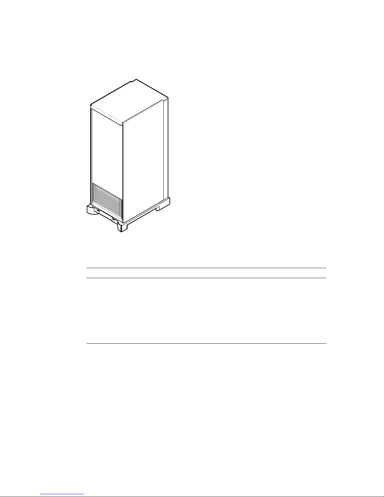
Figure 1–1 DECmpp 12000/Sx Parallel Disk Array
MKV-040000314-82-DG
Table 1–1 PDA Configurations
MODEL SMP11-AA SMP11-AB SMP11-AC
Disk Banks 1 1 2
Data + Parity Disks 4 + 1 8 + 1 16 + 2
Total Disks 5 9 18
Hot Standby (optional) 1 1 1
Total Unformatted
Capacity
Total Formatted Capacity 5.8 Gbytes 11.5 Gbytes 23 Gbytes
6 Gbytes 12 Gbytes 24 Gbytes
1–2 Parallel Disk Array Overview
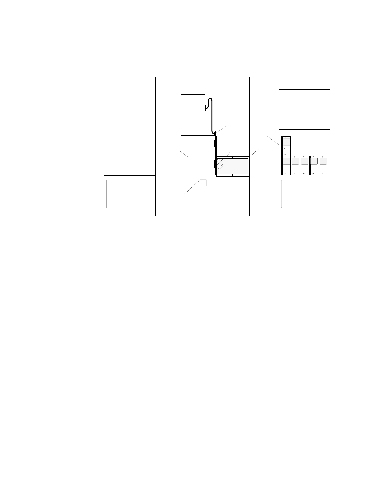
Figure 1–2 Parallel Disk Array, Model SMP11-AA
Disk
Array
Controller
Bank 2
FRONT SIDE REAR
Disk
Array
Controller
Power/Fan Tray
Backplane
MUX PCB
Drive
Canisters
Optional
Standby
Drive
Bank 1
S
P 8
4
6
MKV-040000314-70-MPS
2
Parallel Disk Array Overview 1–3
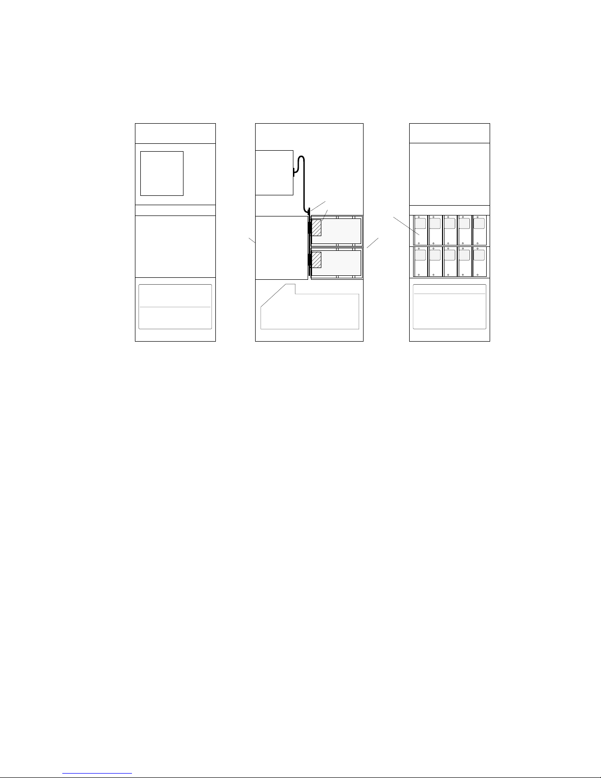
Figure 1–3 Parallel Disk Array, Model SMP11-AB
Disk
Array
Controller
Bank 2
FRONT SIDE REAR
Disk
Array
Controller
Canisters
Canisters
Power/Fan Tray
Backplane
MUX PCB
Drive
Drive
Optional
Standby
Drive
Bank 1
S
P
7
8
MKV-040000314-71-MPS
1
3
5
6
4 2
1–4 Parallel Disk Array Overview
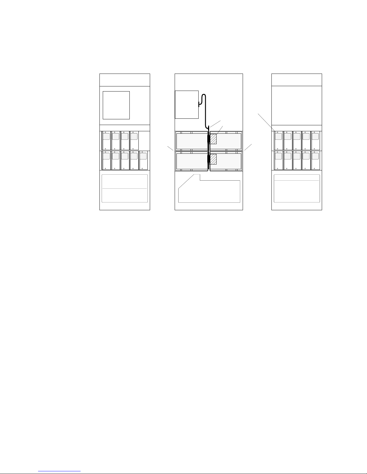
Figure 1–4 Parallel Disk Array, Model SMP11-AC
Disk Disk
Array
Controller
1 3
2
4
FRONT
5
6 8
7
Bank 2
P
Array
Controller
Drive
Canisters
Drive
Canisters
Power/Fan Tray
SIDE
1.1 Parallel Disk Array Components
The PDA has the following major components, which are described individually
in more detail in the sections that follow:
Backplane
MUX PCB
Drive
Canisters
Drive
Canisters
Optional
Standby
Drive
Bank 1
7 5
S
P 8 6
MKV-040000314-72-MPS
3
4
REAR
1
2
• Disk array controller — Contains printed circuit boards (PCBs) controlling
data and parity disk drives; provides a link to the DPU backplane through
the controller’s CPU PCB
• Disk array backplane — Provides power and signal interconnects between
disk canisters and DA controller backplane
• Disk chassis — Contains banks of disk canisters
• Power/fan tray — Contains DC power supplies and a cooling fan
The disk array (DA) controller chassis mounts in the upper-front area of the
PDA enclosure. The disk drive/canister chassis and DA backplane mounts in the
middle of the enclosure. It is 38.86 cm (15.3 inches) high, 48.26 cm (19 inches)
wide, and 0.32 cm (0.125-inch) thick.
The power/fan tray at the bottom of the enclosure contains the DC power supply
and the cooling fan.
Parallel Disk Array Overview 1–5
1.1 Parallel Disk Array Components
1.1.1 Disk Array Controller
The intelligent DA disk controller stores and retrieves data from banks of either
four or eight data disks through printed circuit board (PCBs) connected to
its embedded backplane. Each data PCB can control up to three data disks.
Depending on the configuration, the DA controller can have up to 8 PCBs
controlling up to two banks of data disks; a bank can have four or eight data
disks. Each bank also has one parity disk to support the data disks.
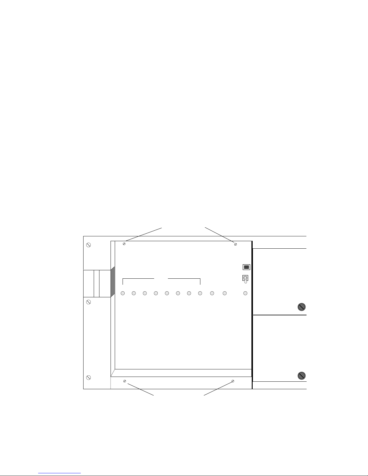
Figure 1–5 shows the DA controller indicators and connectors:
• 10 disk indicators — red during initialization; green when the disk is on line
• Ready indicator (CPU PCB) — red during initialization; green when the
controller is on line
• Reset switch — Forces a powerup system reset (never used during normal
operation)
• Com port — RS-232 serial communication port for offline diagnostics, online
system configuration, maintenance, and controller status monitoring
Figure 1–5 DA Controller Front Panel
Remove 2 Screws
to Access PCBs
DATA
1 2 3 4 5 6
7
8 PAR STDBY
COM
PORT
RESET
READY
1–6 Parallel Disk Array Overview
Loosen 2 Screws
to Access PCBs
MKV-040000314-100-MPS
1.1 Parallel Disk Array Components
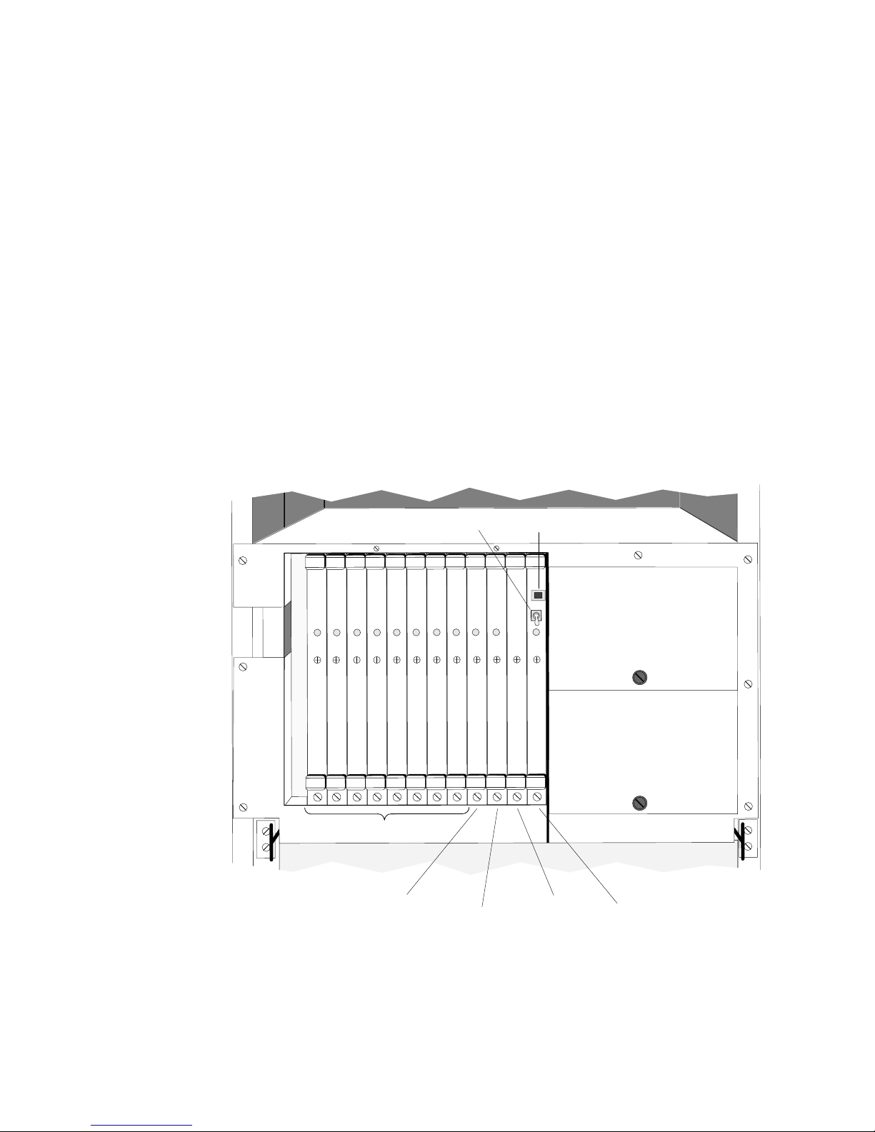
Figure 1–6 shows the PCB slot assignments in the DA controller backplane:
• Slots 1—8: Disk control PCBs
• Slot 9: Parity disk PCB
• Slot 10: Standby disk PCB
• Slot 11: Parity PCB
• Slot 12: Central processing unit (CPU) PCB
The DA controller integrates a master, high-speed interface (HSI) unit on the
CPU and Parity PCBs.
The DA controller mounts on the PDA enclosure rails with slide guides. Hinges
allow the fully extended DA controller to rotate forward 90 degrees, providing
access to its backplane and connectors. The DA controller is 38.1 cm (15 inches)
high, 42.55 cm (16.75 inches) wide, and 28.58 cm (11.25 inches) deep. Two 4-1/4
inch fans mounted on top of the DA controller card cage provide cooling for the
DA controller PCBs.
Figure 1–6 DA Controller Slot Assignments
Reset Switch
Disk Control PCBs
Parity Disk PCB
Standby Disk PCB
(Optional)
COM Port
Parity PCB
CPU PCB
MKV-040000314-73-MPS
Parallel Disk Array Overview 1–7
1.1 Parallel Disk Array Components
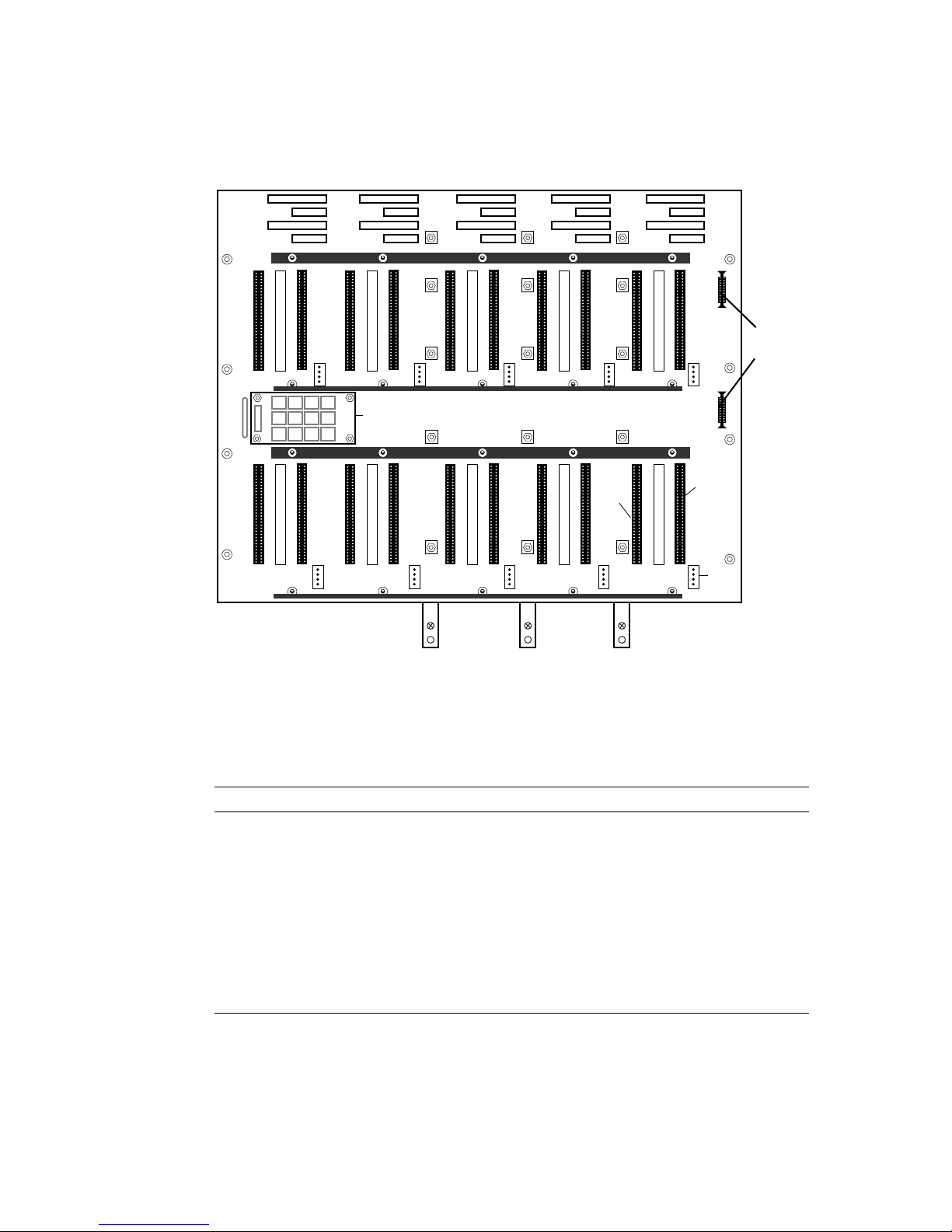
1.1.2 DA Controller Backplane
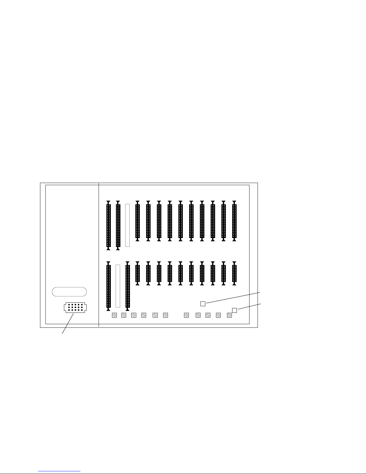
The DA controller backplane (Figure 1–7) has the following connector blocks:
• A1—A10: 34-pin control cable (40-pin connector) to DA backplane connectors
JnP1
• B1—B10: 20-pin data cable to DA backplane connectors JnP2
• A12: 50-pin cable connector conveying control information (command/status)
to/from DA interface PCB in DPU
• B11: 50-pin cable connector conveying data to/from DA interface PCB in DPU
Behind the DA controller, two cable clamps and a gravity guide bar hold the
cables to the DA backplane in place and support the cable slack necessary to
allow the DA controller to rotate forward.
Figure 1–7 DA Controller Backplane
13 12 11
10 9 8 7 6 5 4 3 2 1
CONTROL
DC Power
13 12 11
A
DATA
10 9 8 7 6 5 4 3 2 1
B
+5
GND
MKV-040000314-74-MPS
1–8 Parallel Disk Array Overview
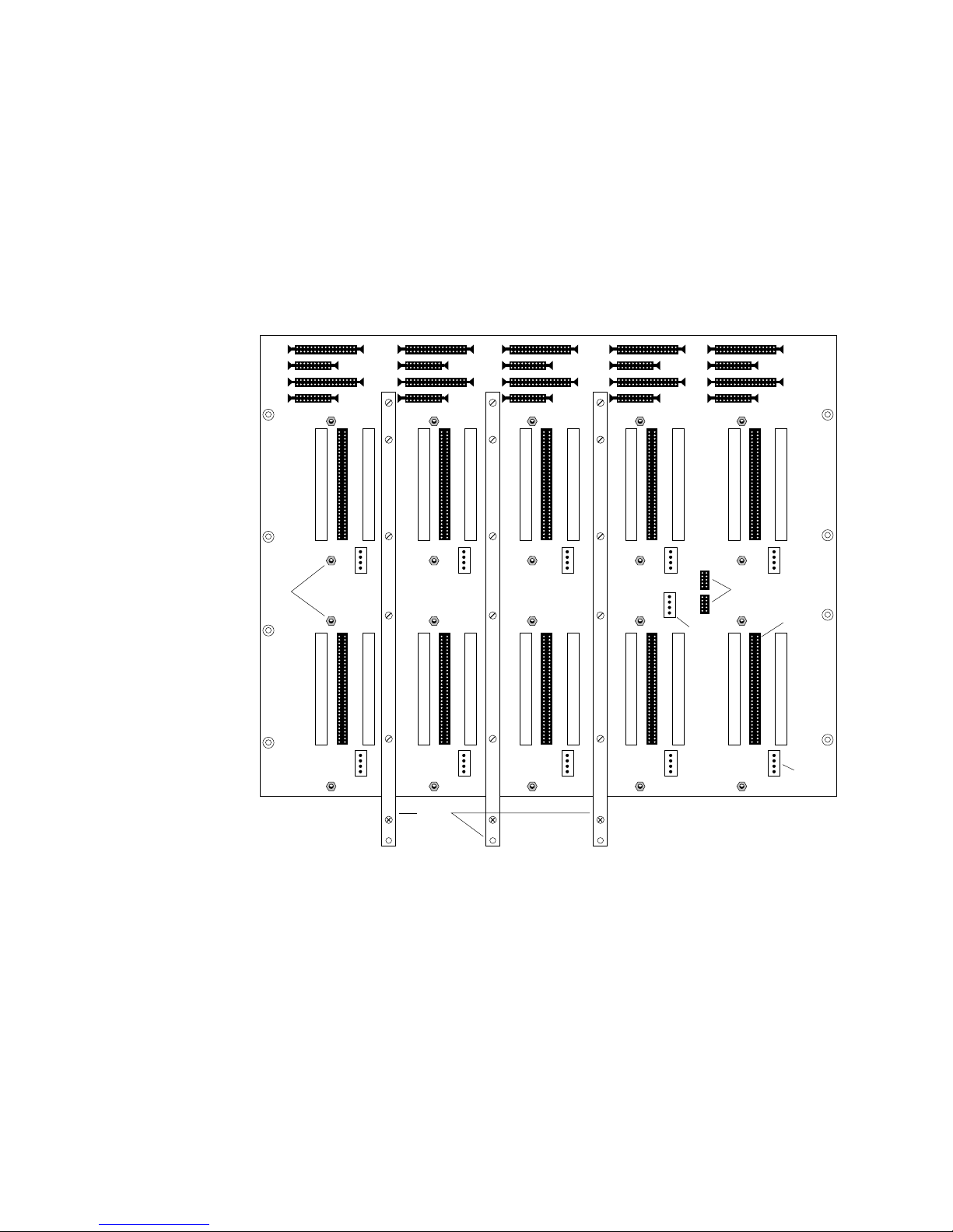
1.1.3 DA Backplane
To support the various PDA configurations, the DA backplane has disk signal
and power connectors on both the front and rear sides. The multiplexer (MUX)
connectors are on the DA backplane rear side. The clock PCB is also on the
DA backplane rear side. Figure 1–8 and Figure 1–9 show both sides of the DA
backplane.
Figure 1–8 DA Drive Backplane (front)
1.1 Parallel Disk Array Components
Pins
J2P1
J2P2
J1P1
J1P2
J1B1
J2B1
J1B2
J2B2
J1M1
J2M1
J4P1
J4P2
J3P1
J3P2
J3B1
J4B1
J3B2
J4B2
J3M1
J6P1
J6P2
J5P1
J5P2
J5B1
J6B1
J5B2
J6B2
J5M1
J6M1
J8P1
J8P2
J7P1
J7P2
J7B1
J8B1
J7B2
J8B2
J7M1
Power
Supply
Sense
Line
J8M1
J9P1
J9P2
JAP1
JAP2
JAB2
JAB1
Clock
PCB
Connectors
J9B2
J9B1
JAM1
Disk
Connect
J9M1
Disk
Power
The controller assignments for each DA backplane connector correspond to the
ESDI J1/P1, J2/P2 pin assignments. The read/write data and clocks, driveselected, and command-complete signals from the DA controller route through
the MUX interconnects. All other signals route directly to the disk canister
interconnects.
The DA backplane provides the following system interconnects: array controller,
disks, MUX, lightpipe, and power.
Power
Bars
GND +5 +12
MKV-040000314-75-MPS
Parallel Disk Array Overview 1–9
1.1 Parallel Disk Array Components
Figure 1–9 DA Drive Backplane (rear)
JAM1
J9M1
JAB2
J9B2
JAB1
J9B1
J7M1
Clock
PCB
J8M1
J7B2
J8B2
J7B1
J8B1
+12
J5M1
J6M1
J5B2
J6B2
J5B1
J6B1
+5
Table 1–2 lists the DA backplane connectors.
J3M1
J4M1
J3B2
J4B2
J3B1
MUX
Connect
J4B1
GND
J1M1
J2M1
J1B1
J1B2
Disk
Connect
J2B1
J2B2
Disk
Power
MKV-040000314-76-MPS
Light Pipe
Connectors
Table 1–2 DA Backplane Connectors
Type Quantity Description
Disk 20 Data signals; 10 on each side of backplane (only 9 are used on
MUX 10 Data and status signals; DA backplane front
J1 10 Command cable from DA controller C1; DA backplane front
J2 10 Data cable from DA controller D1; DA backplane front
Power 20 Disk power; 10 on each side of backplane (only 9 are used on the
Sense line 1 Power sensor from disks to power supply; DA backplane front
Lightpipe 2 Disk status to front panel indicators; DA backplane front
1–10 Parallel Disk Array Overview
the front side)
front side)

1.1.3.1 DA Controller Interconnect
The front of the DA backplane provides connections for two sets of cables from
the DA controller backplane:
• 34-pin command cables
• 20-pin data cables
1.1.3.2 Disk Canister Interconnect
Disk canisters plug directly into the 64-pin connectors. (Sixty pins are used.)
The 4-pin power connectors supply DC voltage to the disk canisters. The DA
backplane interconnects support 20 disk canisters (19 canisters are used) with
the following:
• Disk signals to/from backplane
• Disk-to-disk signals (spindle lock)
• Disk power signals
1.1.3.3 Multiplexer Interconnect
The MUX PCBs plug directly into the DA backplane 64-pin connectors.
Read/write data and clocks, disk-selected, and command-complete signals route
here from the DA controller interconnects and from the disk interconnects. Status
lines to the lightpipe interconnects originate here.
1.1 Parallel Disk Array Components
The DA backplane interconnects provide 10 MUX PCBs with the following:
• Data to/from the disk
• Data to/from the controller
• Drive status signals to the lightpipe and disk-panel indicators
1.1.3.4 Lightpipe Interconnect
The DA backplane has two 10-pin lightpipe connectors. The split ribbon cable
carrying disk status signals to the lightpipe has two separate 10-pin connectors
at one end and a single 50-pin connector on the other, which connects to the
PDA front panel lightpipe. Each lightpipe connector is dedicated to signals from
one side of the DA backplane. For more detail on the lightpipe displays, refer to
Chapter 6.
1.1.3.5 Power Interconnect
A system of bus bars supplies the necessary DC voltage to the +12 VDC, +5 VDC,
and ground planes within the DA backplane. A 4-pin connector provides power to
the disk.
A 4-pin connector provides the sense line connection back to the power supply.
Parallel Disk Array Overview 1–11
1.2 Disk Chassis
1.2 Disk Chassis
The rack-mounted, sheet metal disk chassis is similar to a card cage, containing
modular disk canisters instead of PCBs. The disk chassis has 10 disk canister
slots, arranged five-wide and two-high. The modular disk canisters slide into
the disk chassis on standard nylon card guides and connect to the DA backplane
behind the disk chassis.
The disk chassis is 38.1 cm (15 inches) high, 43.18 cm (17 inches) wide, and 30.48
cm (12 inches) deep.
1.2.1 Disk Canisters
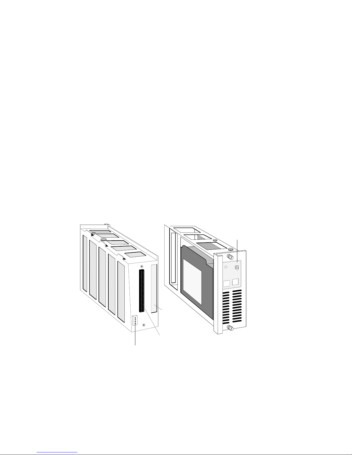
Each modular sheet metal canister contains a 5-1/4 inch ESDI disk drive with
1450 Mbyte formatted capacity. Figure 1–10 shows a disk canister. Front panel
labels identify the disk canister bank number and disk number. The disk canister
front panel also has a power switch, controlling the +12 and +5 voltage to the
canister. The disk canister rear panel has two panel-mounted connectors:
• 64-pin signal connector
• 4-pin power connector
Figure 1–10 Disk Drive Canister
Signal
Connector
Power
Connector
Cutout
for MUX
PCB
Power
Switch
PWR
DRV
RDY
OFF
DRIVE
BANK
MKV-04000314-77-MPS
The indicator on the front of the disk canister is green when the disk is spinning
and off when the disk is not spinning. (The DA controller controls the disk
status.)
1–12 Parallel Disk Array Overview

1.2.2 MUX Printed Circuit Board
Using the MUX PCBs, the DA controller can access up to two banks of disks in
any one PDA enclosure. The MUX PCBs also provide disk status to the PDA
lightpipe and to the disk canister indicators.
The MUX circuitry can be divided into five functional blocks:
• Read data, read clock, drive selected, and command complete multiplexing
• Write data and clocks from array controller to disks
• Provide status to lightpipe indicators
• Provide status to disk canister indicator
• Provide disk sector-pulse monitoring
1.2.2.1 Data Multiplexing
The MUX circuitry multiplexes four groups of signals, two to one:
• Read data (rd)
• Read clocks (rc)
• Command complete (cc_)
1.2 Disk Chassis
• Drive selected (ds_)
The MUX receives read data and read clocks from two different banks, determines
which bank is selected, and passes the appropriate read data and clocks to the
controller.
1.2.2.2 Write Data
Write data and clock signals from the array controller are routed to the bank
selected by the array.
1.2.2.3 Sector Pulse Monitor
The sector monitor is a retriggerable monostable multivibrator. Sector pulses
from the disk keep the output active. If the sector pulse is lost, the output goes
low, signaling that the disk is spun down.
1.3 DPU-PDA Interface Cable
Two 50-pin DPU-PDA interface cables interface the DA controller to the VME 6U
interface PCB (mounted on a Parallel VME 6U Adapter PCB) in the DPU. One
cable carries control information (command/status); the other cable carries data
signals.
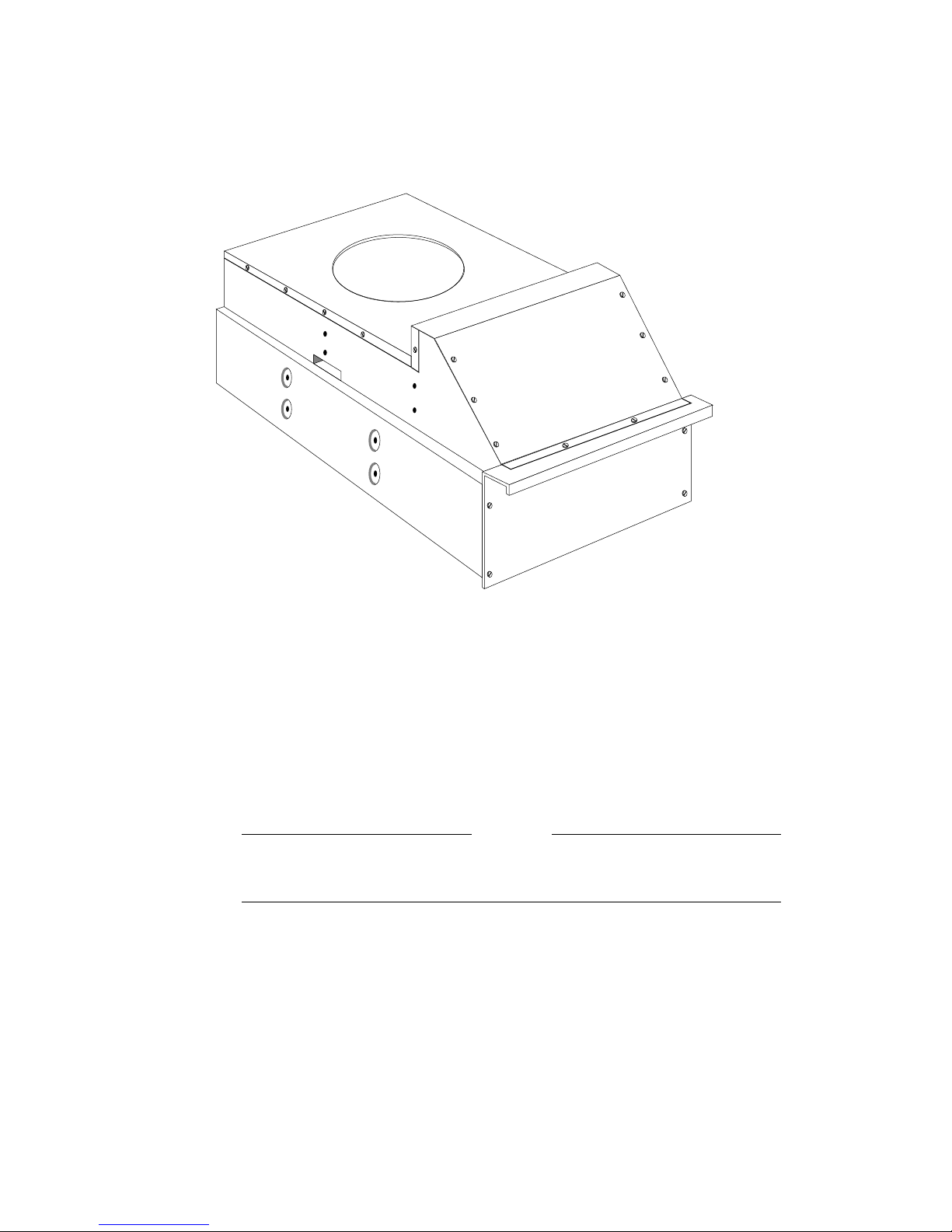
1.4 Power/Fan Tray
The power/fan tray mounted in the bottom of the enclosure contains the complete
power subsystem and the exhaust fan, including AC power connection, 20 A and
1 A circuit breakers. Figure 1–11 provides front and side views of the power/fan
tray.
A set of power distribution connectors allows the complete tray to slide in and
out of the enclosure without having to bolt or unbolt power cables. Only the AC
power cable, the temperature sensor cable, and the lightpipe power cable need to
be detached before removing the tray.
Parallel Disk Array Overview 1–13
1.4 Power/Fan Tray
Figure 1–11 Power/Fan Tray
MKV-040000314-78-MPS
The power selector switch is on the power/fan tray rear panel, inside the PDA
enclosure at the rear. It is a toggle switch that must be pulled out slightly before
it can be moved. It has three positions:
• OVERRIDE (straight up): Powers on the PDA, regardless of other conditions
• LOCAL (middle position): Powers on the PDA independent of the DPU
• REMOTE (lower position): Not used
Warning
DO NOT USE THE OVERRIDE SETTING. It overrides critical safety
systems. The override position is for factory use only.
All PDA configurations use the same power/fan tray. Its rating is:
220 Vac, 20A, 2500 W
Table 1–3 shows the power capabilities of the PDA’s DC power supply.
1–14 Parallel Disk Array Overview

Table 1–3 Power System Capabilities
Voltage Current
+12 Vdc 80 A
–12 Vdc 20 A
+5 Vdc 200 A
–5.2 Vdc 25 A
The power/fan tray is 35.56 cm (14 inches) high, 43.18 cm (17 inches) wide, and
60.96 cm (24 inches) deep. It weighs approximately 41.73 kg (92 pounds).
1.4.1 Power System
The power system consists of the power-sequencing PCB, the DC power supplies,
and power distribution subsystem.
The bus bar system attaches to a high current plug and carries +5 Vdc, +12 Vdc,
and ground to the backplane power plates. The –5.2 Vdc and sense lines attach
to a low current plug.
1.4 Power/Fan Tray
DC power distribution begins with a quick disconnect between the power/fan tray
and the backplane power cables. The quick disconnect consists of high and low
current plugs. One-half of both connectors resides in the power/fan tray (with
associated harnesses). The other half of both connectors is attached to a frame
member and has a harness and backplane bus bars attached to it.
The backplane supplies power to the disk drives and the MUX PCBs. Table 1–4
shows the backplane power requirements.
Table 1–4 Backplane Power Requirements
Purpose Volts Amps Watts
Multiplexer PCBs 5 10 50
Disk Drives 5 29 145
12 51 612
Total 807
The chassis ground circuit detects differences in potential between chassis ground
and logic ground and shuts down the power/fan tray when the potential exceeds a
preset 70 mV threshold.
Figure 1–12 shows the power cables to the DA backplane.
Parallel Disk Array Overview 1–15
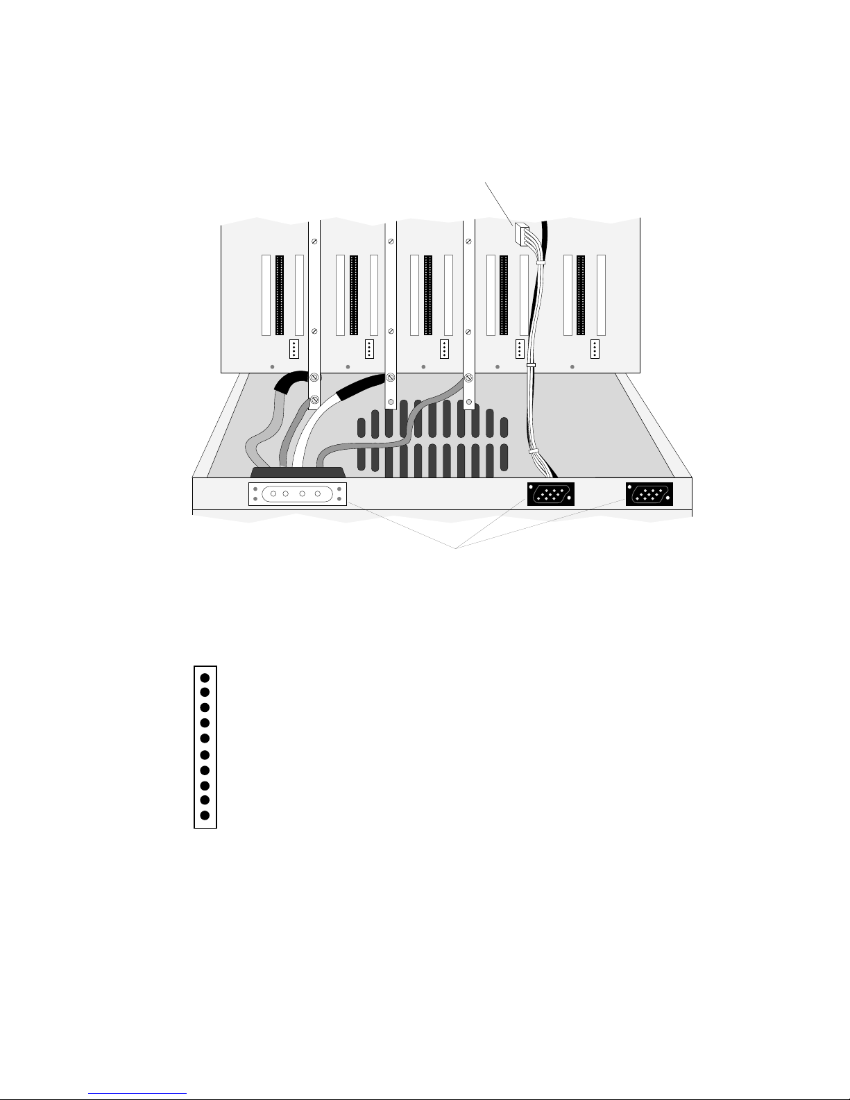
1.4 Power/Fan Tray
MKV−040000314−55−RAGS
Chassis Ground
Temperature
Main Power Vcc +5 V
Main Power Vee −5 V
Main Power +12 V
Main Power −12 V
AUX Power Vcc +5 V
AUX Power Vee −5 V
AUX Power +12 V
AUX Power −12 V
Figure 1–12 Power Bridge and Cables
Power Sense Line Connector
GND
GND
GND
+5
+12
+5
DC Power Connectors
+12
Figure 1–13 Power/Fan Tray Service Indicators
MKV-040000314-79-MPS
1.4.2 Power/Fan Tray Indicators
1–16 Parallel Disk Array Overview
Figure 1–13 shows the ten indicators located on the PDA power/fan tray rear
panel. These indicators provide information about the power/fan tray. They
show the status of some part of the power/fan tray and are green during normal
operation. If a failure is detected, the corresponding indicator changes to red, and
the power tray shuts down. Any red indicators are latched ON, indicating the
problem area, and initiate the power shutdown.

1.4 Power/Fan Tray
Table 1–5 lists the function of each power/fan tray indicator (from the top).
Table 1–5 Power/Fan Tray Service Indicators
Indicator Function
Chassis Ground Green — Normal
Temperature Green — Normal
Main power Vcc +5 V Green — Normal
Main power Vee –5 V Green — Normal
Main power +12 V Green — Normal
Main power –12 V Green — Normal
Auxiliary power Vcc +5 V Green — 15 A breaker is set on
Auxiliary power Vee –5 V Green — 15 A breaker is set on
Auxiliary power +12 V Green — 15 A breaker is set on
Auxiliary power –12 V Green — 15 A breaker is set on
1.4.3 Exhaust Fan
The reverse-curve, radial fan in the enclosure bottom exhausts warm air out of
the enclosure bottom, creating a low-pressure zone in the plenum in the enclosure
center. This low-pressure zone draws air through the air intakes in the top of the
enclosure back door, through the PCBs, and into the plenum.
Red — Logic ground to chassis ground short; excess voltage
detection
Red — Excess temperature
Red — Failure in +5 V supply
Off — indicates problem with power sequencer
Off — indicates problem with power sequencer
Off — indicates problem with power sequencer
Off — indicates problem with power sequencer
The cooling fan performance is 1200 ft3/minute.
Parallel Disk Array Overview 1–17

 Loading...