

Digital Equipment DECwriter 500i, LJ520, DECcolorwriter 520ic, LJ500 Service Manual
DECwriter 500i
DECcolorwriter 520ic
(LJ500 and LJ520)
Service Manual
EK-LJ50E-SV.A01

First Edition - July 1994
The information in this document is subject to change without notice and should
not be construed as a commitment by Digital Equipment Corporation. Digital
Equipment Corporation assumes no responsibility for any errors that may appear
in this document.
Copyright Digital Equipment Corporation 1994
All rights reserved.
Printed in Europe
The following are trademarks of Digital Equipment Corporation:
DEC, DECcolorwriter 520ic, DECwriter 500i and the Digital logo:
TRADEMARKS:
CENTRONICS is a registered trademark of Centronics Data Computer
Corporation EPSON and LQ 850 are registered trademarks of Epson Seiko
Corporation
HP, DeskJet and PCL III + are registered trademarks of Hewlett-Packard
Company
IBM and Proprinter X24 are registered trademarks of International Business
Machines Corporation
MS-DOS and MS-WINDOWS are registered trademarks of Microsoft
Corporation.
UNIX is a registered trademark of UNIX System Laboratories, Inc. in the United
States of America and other countries.

PREFACE
This service manual provides technical, mechanical and electronic information for
product support.
Refer to this manual when a fault has not been corrected using the
recommendations described in the Installation and User Guide included with the
printer.
Summary
This manual is divided into 9 chapters and 1 appendix which contains the list of
recommended spares (FRU). The chapters are organized to develop an
autonomous and gradual approach to printer problems.
Some paragraphs are marked on a dark background and advise the use of
particularly important situations or procedures. If these observations are not
heeded, the printer could malfunction.
Associated Documentation
EK-LJ50*-UG DECwriter 500i & DECcolorwriter 520i -
Installation and User Guide
EK-LJ50*-RF Read-Me-First - DECwriter 500i
EK-LJ52E-RF Read-Me-First - DECcolorwriter 520i
(English only)
The * in the above two part numbers corresponds to the language identifier for the
appropriate language, e.g. F- French, G- German and so on.
Languages supported are English (UK and USA), French, German, Italian and
Spanish
i

FEDERAL COMMUNICATIONS COMMISSION
RADIO FREQUENCY INTERFERENCE STATEMENT
INFORMATION TO THE USER
NOTE: This equipment has been tested and found to comply with the limits for a
Class B digital device pursuant to Part 15 of the FCC Rules. These limits are
designed to provide reasonable protection against harmful interference in a
residential installation. This equipment generates, uses and can radiate radio
frequency energy and, if not installed and used in accordance with the
instructions, may cause harmful interference to radio communications. However,
there is no guarantee that interference will not occur in a particular installation. If
this equipment does cause harmful interference to radio or television reception,
which can be determined by turning the equipment off and on, the user is
encouraged to try to correct the interference by one or more of the following
measures:
• Reorient or relocate the receiving antenna
• Increase the separation between the equipment and receiver
• Connect the equipment to an outlet of a circuit different from that to which
the receiver is connected
• Consult the dealer or an experienced radio/TV technician for assistance.
Changes or modifications not expressly approved by the party responsible for
compliance could void the user’s authority to operate the equipment. Connecting
of peripherals requires the use of grounded shielded cables.
EMI Requirements for Canadian Market
This digital apparatus does not exceed the class B limits for radio noise emissions
from digital apparatuses as set forth in the radio interference regulations of the
Canadian Department of Communications.
Spécifications EMI pour le Marché Canadien
Le présent appareil numérique n’emet pas de bruits radioélectriques dépassant les
limites applicables aux appareils numériques de classe B prescrites dans le
reglement sur le brouillage radioélectrique edicté par le Ministere des
Communications du Canada.
This equipment conforms to the specifications of EEC directive 87/308 on the
prevention and elimination of radio-frequency disturbances.
NOTICE Digital Equipment Corp. reserves the right to modify the equipment described in this
manual at any time and without notice.
ii

Contents
PREFACE ....................................................................................................i
Summary...................................................................................................... i
Associated Documentation............................................................................i
FEDERAL COMMUNICATIONS COMMISSION RADIO FREQUENCY
INTERFERENCE STATEMENT.................................................................ii
Contents ....................................................................................................... iii
1. GENERAL
1.1 INTRODUCTION..................................................................................1-1
1.2 TECHNICAL CHARACTERISTICS.....................................................1-2
1.3 FIRMWARE AND CHARACTER GENERATORS ..............................1-5
Basic emulations...........................................................................................1-5
Optional emulations:.............................................................................. 1-5
Character generator:...............................................................................1-5
Character set:.........................................................................................1-6
Basic emulation optional fonts:..............................................................1-8
1- "Prestige Elite" card (256 Kbytes)............................................ 1-8
2- "Times Nordic" card (256 Kbytes)............................................1-9
3- "Nordic" card (256 Kbytes)...................................................... 1-9
1.4 Product OPTIONS .................................................................................1-9
2. FUNCTIONAL DESCRIPTION
2.1 GENERAL BLOCK DIAGRAM ...........................................................2-1
2.2 Printer Components and Internals ..........................................................2-2
2.3 BLACK INK-JET HEAD FUNCTIONING............................................ 2-5
Ink jet head description:......................................................................... 2-5
How an Ink-jet works............................................................................. 2-6
The nozzles:...........................................................................................2-8
2.4 COLOR INK-JET HEAD FUNCTIONING............................................. 2-10
Ink jet head description:......................................................................... 2-10
Ink jet printing functioning principle:.....................................................2-12
The nozzles:........................................................................................... 2-12
Resistor enabling circuit specifications:................................................. 2-13
2.5 OPERATING CONTROLS.................................................................... 2-14
Operator Panel.......................................................................................2-14
Key functions.........................................................................................2-15
2.6 COLOR SELECTION LEVER............................................................... 2-18
iii

3. INSTALLATION
3.1 GENERAL INSTRUCTIONS.................................................................3-1
Mains power supply:..............................................................................3-1
Environmental conditions:..................................................................... 3-1
Product positioning:...............................................................................3-1
3.2 UNPACKING.........................................................................................3-2
Packing check:....................................................................................... 3-2
3.3 CONNECTION TO THE MAINS........................................................... 3-3
3.4 INSTALLING THE PRINT HEAD.........................................................3-3
3.5 INSERTING AN OPTIONAL MEMORY/FONT CARD........................3-5
3.6 PAPER FEED.........................................................................................3-6
ASF sheet feed:......................................................................................3-6
Manual insertion:...................................................................................3-8
3.7 SPROCKET INSTALLATION...............................................................3-10
Paper loading by sprocket:.....................................................................3-10
3.8 2nd PAPER TRAY (ASF2) INSTALLATION ........................................3-11
Paper insertion from second ASF drawer: ..............................................3-11
3.10 SERIAL INTERFACE INSTALLATION ............................................. 3-12
3.11 PRINT TEST........................................................................................3-13
3.12 SYSTEM CONNECTION.....................................................................3-13
Centronics parallel interface .................................................................. 3-13
3.13 SWITCHING OFF THE PRINTER....................................................... 3-15
3.14. INSTALLATION SET UP.................................................................. 3-15
DEFAULT parameters...........................................................................3-16
PROGRAMMABLE PARAMETERS....................................................3-17
SYSTEM PARAMETER SET-UP......................................................... 3-22
4. USER MAINTENANCE
4.1 NOZZLE CLEANING AND INK RESET (“PRIME”)......................... 4-1
Nozzle cleaning:....................................................................................4-1
Ink reset ( ”PRIME” ) Black head only..................................................4-2
Black Ink jet head cleaning and maintenance:........................................ 4-3
Color Ink jet head cleaning and maintenance:........................................4-4
iv

5. DIAGNOSTICS AND TESTS
5.1 AUTODIAGNOSTICS AT POWER-ON ................................................ 5-1
5.2 PRINT TEST WITH BLACK PRINT HEAD..........................................5-1
5.3 PRINT TEST WITH COLOR PRINT HEAD..........................................5-3
5.4 ”DATA SCOPE” PRINTOUT (HEX DUMP) .......................................5-4
Enabling the Data Scope printout:.......................................................... 5-4
Disabling the Data Scope printout:........................................................ 5-4
5.5 DIAGNOSIS GUIDELINES .................................................................. 5-5
6. FAULT CONDITIONS AND MEANING
OPERATIONAL STATUS...........................................................................6-1
Fault Conditions and Indications............................................................6-2
Normal Conditions and Indications........................................................6-3
7 MECHANICAL ADJUSTMENTS
7.1 PRINT HEAD AND THE WRITING SURFACE GAP..........................7-1
Procedure:..............................................................................................7-1
7.2 ADJUSTING THE TENSION OF THE PAPER FEED MOTOR BELT..7-2
Procedure:..............................................................................................7-2
7.3 BI-DIRECTIONAL PRINT ALIGNMENT ADJUSTMENT...................7-3
8. ELECTRICAL INTERCONNECTIONS
8.1 MAIN BOARD MAIN COMPONENTS.................................................8-1
8.2 POWER SUPPLY BOARD.....................................................................8-2
8.3 POWER SUPPLY CIRCUIT ON MAIN BOARD................................... 8-3
8.4 CONNECTOR SIGNALS.......................................................................8-4
v

9. PARTS REPLACEMENT
9.1 WARNING NOTES................................................................................9-1
9.2 REPLACING THE INK CARTRIDGE:..................................................9-2
9.3 DISASSEMBLING/ RE-ASSEMBLING THE PRINT HEAD: ..............9-3
9.4 DISASSEMBLING / RE-ASSEMBLING THE CASING........................ 9-4
9.5 DISASSEMBLING / RE-ASSEMBLING THE MAIN BOARD: ............9-6
9.6 DISASSEMBLING/ RE-ASSEMBLING THE OPERATOR PANEL: ....9-8
9.7 DISASSEMBLING / RE-ASSEMBLING THE POWER SUPPLY BOARD: 9-9
9.8 DISASSEMBLING / RE-ASSEMBLING THE PAPER FEED MOTOR.9-11
9.9 DISASSEMBLING / RE-ASSEMBLING THE CARRIAGE MOTOR.... 9-12
9.10 DISASSEMBLING / RE-ASSEMBLING THE BLACK/COLOR SELECTION
AND SHEET PRESENCE PHOTOSENSORS..............................................9-13
9.11 DISASSEMBLING / RE-ASSEMBLING THE LINEAR ENCODER... 9-14
9.12 DISASSEMBLING / RE-ASSEMBLING THE PRINT CARRIAGE.....9-15
9.13 DISASSEMBLING / RE-ASSEMBLING THE PAPER OUTFEED GROUP 9-16
A. SPARE PARTS and OPTIONS List
vi

1.1 INTRODUCTION
The LJ500 and LJ520 are "bubble ink jet" printers that combine excellent
quality printing with a fast writing speed, a low noise level and considerable
versatility in the paper handling. With these qualities they can compete with many
Laser Printers.
This service manual is intended for the DECwriter 500i monochrome inkjet
printer with color option, and the DECcolorwriter 520ic color inkjet printer
otherwise known as the LJ500 and LJ520. The only difference is that the color
model is shipped with the color kit, and the monochrome model can be upgraded
with the color kit, which has to be ordered separately. In all other respects the two
printers are identical and therefore all instructions and operations described in this
manual are applicable to both printer models, unless reference is made to a
specific model.
This non-impact printer is designed and constructed to guarantee reliability and to
give constant quality of both text and high resolution graphics. It uses “drop on
demand” thermal ink jet technology with a monochrome (black) or colour
disposable print head, associated with very low power consumption (25W - less
than a standard light bulb). It produces a laser-like print density of up to 300 x
300 dots per inch (dpi) with minimal operating disturbance. The monochrome
print head has a rechargeable system and its ink is water- resistant.
1. GENERAL
This printer can be connected to personal computers with a standard parallel or
optional serial interface. Compatible with MS-Windows and many other software
applications commonly used with this class of printer, it can be used in most
working environments. The resident firmware emulates the HP DeskJet 500C
printer (extended PCL-III commands).
General 1-1

1.2 TECHNICAL CHARACTERISTICS
Printing Technique Non-impact, bubble ink jet
Print Head Disposable Black or Color
Black Vertical resolution: 300 dpi
Repetition frequency: 5000 Hz
Nozzles: 50 (in 4 groups of 12 or 13)
Vertical construction: 2 cols of 25 nozzles
Water-resistant ink
Ink cartridge life: 90,000,000 dots
(400,000 characters,, average or 400 pages)
Replaceable ink cartridges
No. cartridges per print head: up to 10
(depending on usage: work load and storage)
Color Vertical resolution: 300 dpi
Repetition frequency: 3000 Hz
Nozzles: 51 (in 3 vertical groups: yellow, magenta, cyan)
Vertical construction: 2 cols, one of 25 and one of 26
nozzles
Print head life: 200 pages at 8% coverage
Print Matrix, 300 x 300 dpi
Print Definition
(Vertical x Horizontal) 1/300 in x 1/100 in for Draft
Print Density 75, 100, 150, 300 dpi
Print Pitch 10, 12, 16.67 cpi; PS
Print Orientation Portrait and Landscape
Print Line Length (A4 paper size),
General 1-2
1/300 in x 1/150 in for NLQ
1/300 in x 1/300 in for LQ
(rows shifted by 1/600 in.)
Each basic fixed pitch value can be condensed to
half and expanded to double its value
(e.g.: 10cpi: 5 cpi / 20cpi)
Portrait orientation: - 80 characters with 10 cpi pitch
- 96 characters with 12 cpi
- 132 characters with 16.67 cpi pitch

Landscape orientation: - 112 characters with 10 cpi pitch
- 134 characters with 12 cpi
- 186 characters with 16.67 cpi
Printing Speed DOS and similar environments:
400 cps in Draft
280 cps in NLQ
160 cps in LQ
Windows and similar environments:
DRAFT : up to 5 ppm (pages per minute)
NLQ : up to 4 ppm
Letter Quality : up to 3 ppm
(these values may vary depending on the
softwareapplication and/or the type of
computer used)
Work Load should not exceed 350 pages per day nor 1000 pages
per month, including 160 color pages
Printer Life 5 years
Print Path Bi-directional
Graphic Printing Bit Image Mode - density: 300 x 300 dpi
Ink Save Mode 10% ink saving in graphics mode
Linespacing Elementary value: 1/300 in
Resident value: 1/6 in (4.23 mm)
Printer Emulation Resident : PCL III +
Optional : IBM -X24/EPSON LQ 850
(available on Emulation card)
Paper Handling -Automatic: ASF1 (tray capacity:120x80g/m2 shts.)
Manual: including thick documents, film,
envelopes (weight up to 135 g/m2)
(see Chap. 3 User Guide for paper characteristics)
Optional: ASF2; tractor (for fan-fold stationery)
Interface Resident: parallel (Centronics)
Optional: serial (EIA RS 232C)
RAM 128K bytes
Operating Environment Temperature: 15 to 35oC
Relative Humidity: 15% - 85%
General 1-3

Noise Emittance Less than 50 dBA in LQ mode
Electrical Characteristics Voltage:
-110 - 120 V; +/- 10%
-120 - 240 V; + 6% / - 10%
Frequency: 50 or 60 Hz
Power absorbed: < 25 W
Certification
For mains voltage 115 V (USA and Canada):,
Electromagnetic Compatibility FCC Class B “Certified”
Safety Regulations, USA: UL 1950/478 Canada: CSA C22.2
For mains voltage 220 - 240 V,
Electromagnetic Compatibility
EN 55022 Class B CEE 87/308
VDE 0871 level B (DBP Verf.243/1991)
Safety Regulations
EN 60950 + Nordic Deviations
Germany: GS (EN 60950/9.88 eZH/618)
Physical Characteristics, Basic printer ready for use
General 1-4
Height - 6.81 in (173 mm)
Width - 15.15 in (385 mm)
Depth - 18.34 in (466 mm)
Weight, - 11 lbs (5 kg)

1.3 FIRMWARE AND CHARACTER GENERATORS
Basic emulations
The basic firmware, contained on 1 Mbyte ROM assembled on the BA X100
board, emulates the HP Deskjet 500 and HP Deskjet 500C printers, with the
corresponding character generators.
The machine automatically makes the selection between the two emulations
according to the type of cartridge installed (black ink cartridge: HP Deskjet 500;
color inks cartridge: HP Deskjet 500C).
Optional emulations:
The available optional emulations are EPSON LQ 850 and IBM Proprinter 4207.
Each emulation includes the relevant set of characters and both are contained on a
specific card.
The optional emulations cannot handle optional fonts on the memory card. To
enlarge the LQ 850 and 4207 emulation graphic fonts, the memory extension
memory card must be inserted to handle the DLL functions (Down Line
Loading).
Character generator:
The task of the character generator is to assign a specific printable character to
each code included in the graphic set.
The first 128 codes in the ISO table (0-127)are the standard USA ASCII
character set. This group does not include national variations or semigraphic
symbols.
The assignment of the codes included in the second ISO set table (128-255)
varies from country to country and from product to product.
_______________________ Note _____________________________
For full and up-to-date details of the character sets and command
codes, please refer to Appendix D of the User Guide
General 1-5

Character set:
The character sets in the machine and available for all resident or optional fonts
are the following:
CP 437 International; ROMAN 8;
PC 8 Denmark/Norway; PC-850 Multilanguage/Latin 1;
ECMA 94 LATIN 1 ISO 8859/1; ISO Nb 4 United Kingdom;
ISO Nb 21 Germany EPSON 02; ISO Nb 69 France;
ISO Nb 15 ITALY; ISO Nb 60 Norway 1;
ISO Nb 61 Norway 2; ISO Nb 11 Sweden: Names EPSON
05; ISO Nb 10 Sweden; ISO Nb 17 Spain;
ISO Nb 6 USA (ASCII) EPSON 00; ISO Nb 2 IRV;
ISO Nb 16 Portugal; ISO Nb 14 JIS ASCII;
LEGAL; CP 860 Portugal;
Denmark OPE 1 ; UNIX International;
Denmark OPE 2; Spain2;
CP 863 French/Canadian.
Further character sets in the machine and available for the ROM resident fonts
(Courier, Letter Gothic and Times Nordic) are:
PC WIN1 (ANSI WINDOWS 3.1); CP 852 Latin 2;
ISO 8859/2 Latin 2; PC WIN2 (East Europe. Win 3.1);
CP 857 Turkish (Latin 5); ISO 8859/9 Latin 5;
PC WIN3 Turkish Win 3.1 (Latin 5); CP 866 Cyrillic;
CP 855 Cyrillic; ISO 8859/5 Cyrillic;
PC WIN4 (Cyrillic Windows 3.1); CP 210 Greek;
CP 851 Greek; ISO 8859 Greek;
PC WIN5 (Greek Windows 3.1); CP 862 Hebrew;
ISO 8859/8 Hebrew; PC Slovenia;
PC Kamenicky.
Resident fonts:
The character fonts in the machine firmware are divided according to the
required page format: vertical or horizontal.
The list of the available fonts is shown in the tables that follow, that also indicate
the possible character heights (in print dots) and spacing (in characters per inch).
General 1-6

Fonts for vertical page format
Pitch
5 / 10 / 20
5 / 10 / 20
8,33 / 16,67 / 33,34
5 / 10 / 20
6 / 12 / 24
6 / 12 / 24
8,33 / 16,67 / 33,34
Proportional
Proportional
Proportional
Proportional
Proportional
Proportional
Proportional
Proportional
Proportional
Proportional
Proportional
Proportional
Proportional
Proportional
Proportional
Proportional
Style Height
Courier 6 / 12
Courier italic 6 / 12
Courier 6 / 12
Letter Gothic 6 / 12
Letter Gothic 6 / 12
Letter Gothic italic 6 / 12
Letter Gothic 4,75 / 9,5
TMS Nordic 6 / 12
TMS Nordic italic 6 / 12
BF Times 7 / 14
BF Times italic 7 / 14
BF Times 6 / 12
BF Times italic 6 / 12
BF Times 5 / 10
BF Times italic 5 / 10
BF Times 4 / 8
BF Times italic 4 / 8
Line 7 / 14
Line italic 6 / 12
Line 6 / 12
Line 5 / 10
Line italic 5 / 10
Line 4 / 8
General 1-7
Fonts for horizontal page format
Pitch
10 / 20
10 / 20
16,67 / 33,34
12 / 24
16,67 / 33,34
Style Height
Courier 6 / 12 / 24
Courier italic 6 / 12 / 24
Courier 6 / 12 / 24
Letter Gothic 6 / 12 / 24
Letter Gothic 4,75 / 9,5 / 19
Basic emulation optional fonts:
An ISO code character set that is the same as the basic character generator but
with a different style. These fonts are on optional cards, and the contents of the
card are given below:
1- "Prestige Elite" card (256 Kbytes)
Style Height Pitch Page format N0 Setup
Prestige Elite 10 12 Vertical 101
Prestige Elite italic 10 12 Vertical 102
Prestige Elite 7 16.67 Vertical 103
Letter Gothic italic 12 12 Horizontal 104
Line Draw 10 12 Vertical
Math Prestige 10 12 Vertical
Math Prestige 12 16.67 Vertical
Pi Font Prestige 10 12 Vertical
Pi Font Prestige 7 17.67 Vertical
General 1-8
2- "Times Nordic" card (256 Kbytes)
Style Height Pitch Page format N0 Setup
Times Nordic 30 Proportional Vertical 111
Times Nordic 14 Proportional Vertical 112
Times Nordic italic 14 Proportional Vertical 112
Times Nordic 12 Proportional Vertical 114
Times Nordic italic 12 Proportional Vertical 115
Times Nordic 10 Proportional Vertical 116
Times Nordic italic 10 Proportional Vertical 117
Times Nordic 8 Proportional Vertical 118
Times Nordic italic 8 Proportional Vertical 119
3- "Nordic" card (256 Kbytes)
Style Height Pitch Page format N0 Setup
Nordic 30 Proportional Vertical 121
Nordic 14 Proportional Vertical 122
Nordic italic 14 Proportional Vertical 122
Nordic 12 Proportional Vertical 124
Nordic italic 12 Proportional Vertical 125
Nordic 10 Proportional Vertical 126
Nordic italic 10 Proportional Vertical 127
Nordic 8 Proportional Vertical 128
Nordic italic 8 Proportional Vertical 129
1.4 Product OPTIONS
All the options can be installed by the operator following the instructions enclosed
with the package.
For full details see the appropriate section in the User's Guide.
General 1-9

2. FUNCTIONAL DESCRIPTION
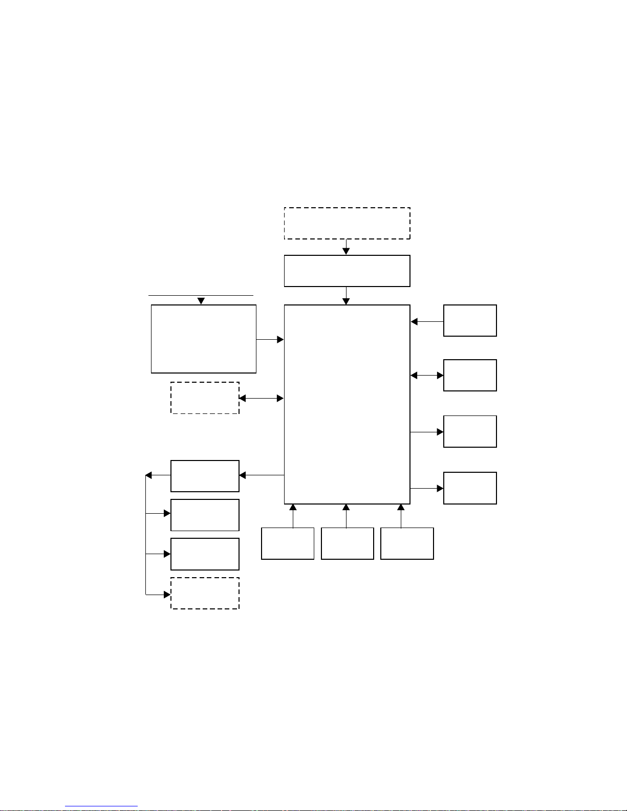
2.1 GENERAL BLOCK DIAGRAM
SERIAL INTERFACE
(RS 232)CABLE:
PARALLEL INTERFACE
MAINS
(CENTRONICS)
MAINS GROUP:
- TRANSFORMER
220-240V 50/60Hz
100-120V 50/60 Hz
- FUSE
- MAINS SWITCH
ASF2
PAPER MOTOR
ASF1
MANUAL PAPER
AND ENVELOPES
INSERTION
PUSHER
SPROCKET
PAPER
PRESENCE
PHOTOSENSOR
MAIN BOARD
BLACK/COLOR
SELECTION
PHOTOSENSOR
CARRIAGE
ENCODER
PHOTOSENSOR
MEMORY
CARD
CONSOLE
CARRIAGE
MOTOR
PRINT HEAD
Note: The blocks with dashed lines are options
Functional Description 2-1

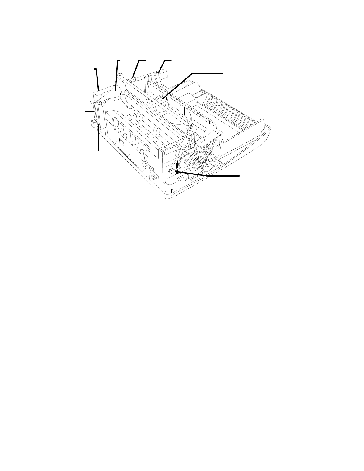
2.2 Printer Components and Internals
The following two figures show the main components and the internals the
printer:
3
16
15
12
1
2
11
10
13
14
17
19
18
4
5
6
7
8
9
19
18
Functional Description 2-2
19
Fig. 2-1 Main Components
19

Front View
1 Top Cover
2 Paper insertion slot (for manual feed)
3 Slot for optional emulation/font card
4 Ink jet print head
5 Print head carriage
6 Print head selection lever
7 Operator Panel
8 Paper output tray
9 Paper input tray
10 ON/OFF switch
11 Ink tube
12 Ink slide
Rear view
13 Manual Feed paper insertion slot cover
14 Power cable socket
15 Socket for optional ASF 2
16 Parallel interface cable
17 Electrical data plate
Underside View
18 Mounting points for optional ASF-2
19 Printer feet
Functional Description 2-3
1
2
5
4
3
Fig. 2-2 Internal Functional Groups
1 Print Head
2 Paper movement step motor
3 ASF-2 connector
4 Parallel interface connector
5 Main Board
6 Carriage transport DC motor
7 PCMCIA card (optional) connector
8 Black/Color selection lever
876
Functional Description 2-4
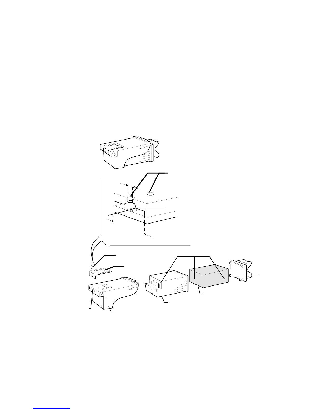
2.3 BLACK INK-JET HEAD FUNCTIONING
NOZZLE
SELECTION
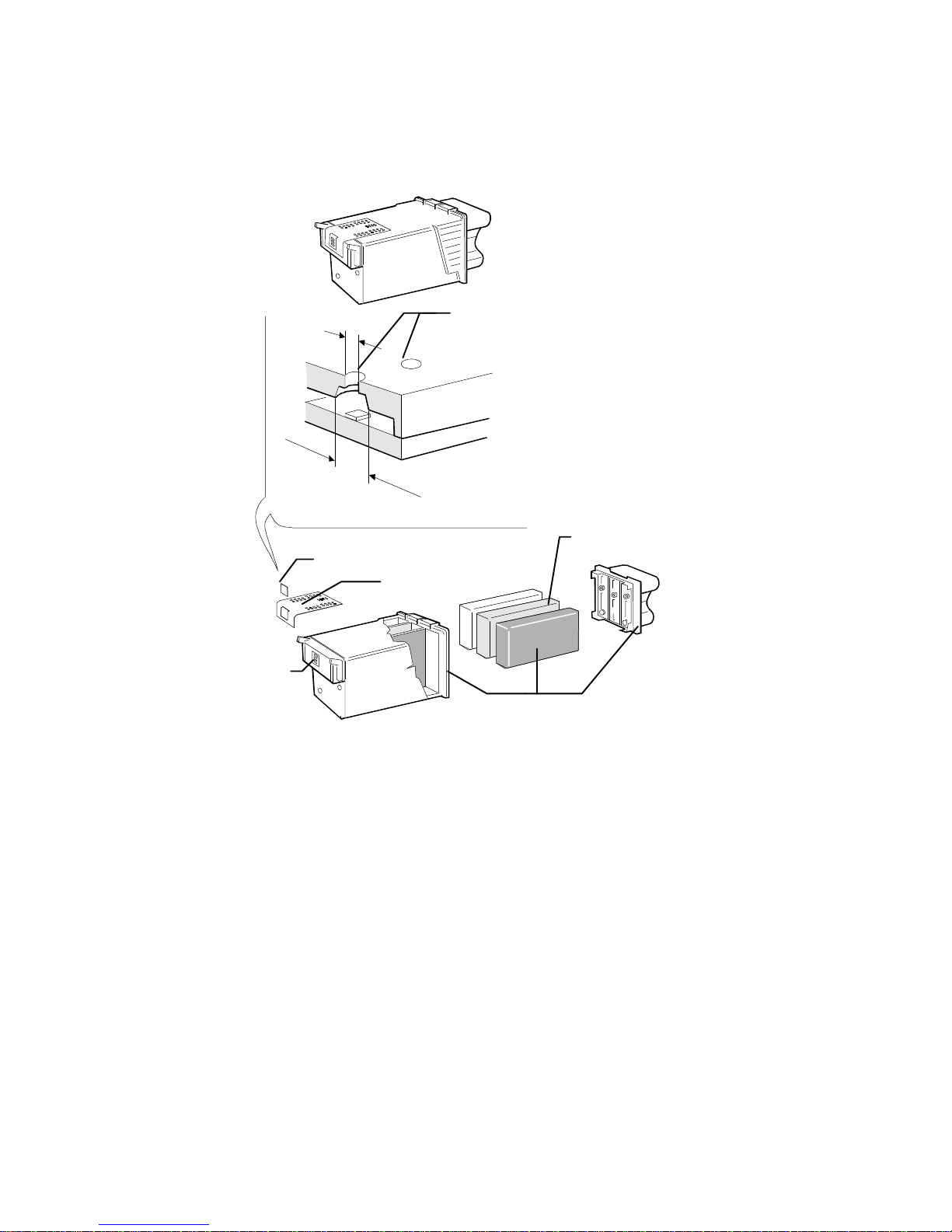
Ink jet head Description:
This consists of an interchangeable sealed container containing 50 print nozzles
and an electric circuit including 50 miniresistors (Fig. 2-3). The nozzles are
assembled on a Nickel and Gold composition called "electroformed". These have
a conical structure, as illustrated in figure 2-3.
The ink, contained in a sponge cartridge, is connected to the nozzles via channels
in the resin layer of the head. This layer is electrically insulated from the
miniresistors. The miniresistors are aligned to the nozzles and connected
electrically to the external head contacts.
INK JET HEAD
INK JET CARTRIDGE
Nozzle
50µm
Resistor
&
140-150µm
Resistor/Nozzle pad
Flexible Electric grid
Ink Jet Head
Fig 2-3 Ink jet head - Black
Ink Cartridge
Cover
Ink Sponge
Container
Functional Description 2-5

How an Ink-jet Works:
Every single nozzle generates an ink bubble each time the relative resistor is
powered for a few nanoseconds.
When the resistor heats up, the ink touching it evaporates.
This phenomena determines the formation of a bubble which quickly expands and
compresses the remaining liquid inside the nozzle. A part of the ink "bubble" is
ejected out via the nozzle hole at a speed of approximately 15m/s.
Figure 2-4a/e illustrate the prominent bubble formation and ejection phases.
Once the resistor power supply command is terminated, the evaporated ink bubble
is broken down and a quantity of ink equal to that ejected is reinstored for
channeling in the nozzle vein.
At this point, the eject command for a new bubble can begin.
Functional Description 2-6

NOZZLE
Fig. 2-4a
INITIAL STATUS
Fig. 2-4b
THE RESISTOR HEATS UP AND
STARTS TO FORM VAPOR
BUBBLE.
THE INK EXITS FROM THE
NOZZLE.
Fig. 2-4c
THE BUBBLE REACHES ITS
MAXIMUM DIMENSION.
Fig. 2-4d
Fig 2-4 Ink Bubble Formation
THE BUBBLE BREAKS DOWN
AND AN INK BUBBLE IS
EJECTED.
Fig. 2-4e
THE INK IS RESET, FOR
CHANNELLING, IN THE NOZZLE.
Functional Description 2-7
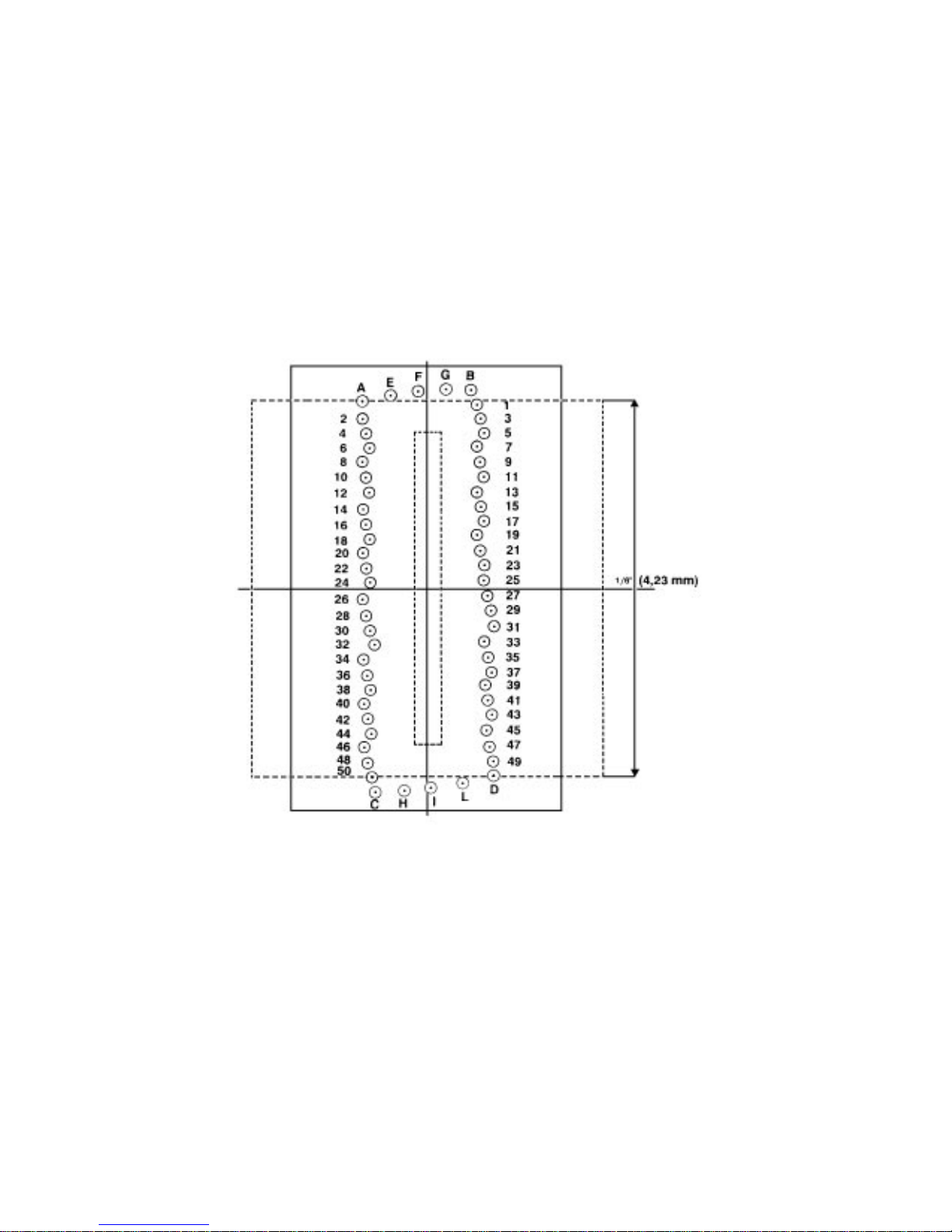
The nozzles:
The print nozzles (1-50) are placed on two columns, each containing 25 nozzles.
They are placed in sequence on each column as illustrated in figure 2-5.
In addition, the matrix is made up of:
• A,C and B,D nozzles with 2.50 and 1.49 extreme print nozzle
damper/equilibrator functions.
• E-L cartridge equilibrator nozzles.
Functional Description 2-8
Fig 2-5 Nozzle Matrix
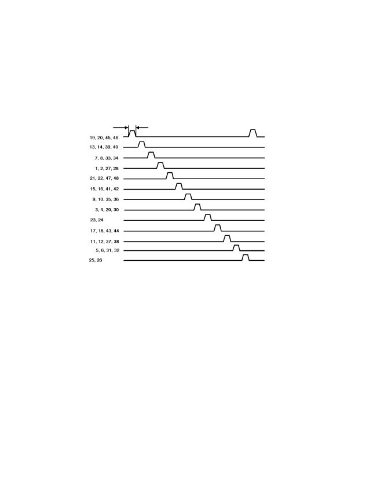
Resistors actuation circuit specifications:
The resistors are divided into four groups; two of which contain 12 resistors and
two 13. Each group can be controlled by only one resistor at a time and therefore
no more than 4 resistors can be controlled simultaneously.
In addition, to avoid induction phenomenon’s between adjacent resistors/nozzles,
the drive will be carried out in a particular sequence (Fig. 2-6).
Fig 2-6 Resistor drive sequence
Each resistor group is controlled by a 18.8 V driver circuit. For correct head
functions, the above voltage must be stabilized.
Characteristic disadvantages which could occur with lower voltages are: lack of
bubble ejection if the head is not used for a short period, lack of bubble ejection
with low temperature. Higher voltage may provoke excess bubble commands or
the absence of command due a resistor deterioration.
Functional Description 2-9

2.4 COLOR INK-JET HEAD FUNCTIONING
Color Ink jet head Description:
The color ink jet head has a replaceable sealed container that contains 51 printing
nozzles, three liquid ink containers, one for each basic color, and an electric
circuit with 51 miniresistors (Fig. 2-7a).
The nozzles are divided as follows between the three basic colors:
- Yellow: 18 nozzles
- Magenta: 17 nozzles
- Cyan: 16 nozzles
The nozzle construction technology is the same as for the monochrome ink jet:
they are obtained from a Nickel and Gold compound called "electroformed". They
have a tapered structure as can be seen in figure 2-7b.
The ink is in three containers, one for each color.
Inside each of these containers there is a sponge to prevent the ink from shaking
when the head is moving thus avoiding possible interference in the carriage
translation, spillage from the vent holes and the formation of froth.
The ink arrives at the corresponding nozzles through channels in the resin layer
of the head. This layer is electrically isolated from the miniressitors.
The miniresistors are positioned to correspond to the nozzles and are connected
electrically with the head external contacts.
Functional Description 2-10
50µm
Ink Sponges
Resistor/Nozzle Pad
Fig 2.7a - Ink jet Head
for Color Inks
Nozzle
Fig 2.7b Nozzle Section
140-150µm
Flexible Electric grid
Ink filter
Ink Cartridge
Fig 2-7 Color head
Functional Description 2-11

Ink jet printing functioning principle:
See section 2.8 where this has already been dealt with.
The nozzles:
The print nozzles (1-51) are placed vertically on two columns, containing
respectively 25 and 26 nozzles , and horizontally in three groups, one for each
color.
They are placed in sequence on each row of nozzles as illustrated in figure 2.8.
Yellow
2
4
6
8
Magenta
20
22
24
26
1
3
5
7
19
21
23
25
Functional Description 2-12
Cyan
44
46
48
50
Fig 2-8 Nozzle Matrixes
45
47
49
51
 Loading...