

Digital Equipment DECcolorwriter 1000 Service Manual

Service Manual
DECcolorwriter 1000
Color Printer
Warning
The following servicing instructions are for
use by quali fied service personnel only. To
avoid personal injury, do not perform any
servicing other than that contained in
operating instruc tions unl ess you are qualified
to do so.
First printing February 1994
Order Number: EK-LF02E-FM.A01
Digital Equipment Corporation
Maynard, Massachusetts U.S.A.

If acquired subject to FAR or DFARS, the following shall apply:
n Unpublished — rights reserved under the copyright laws of the United States.
n Restricted Ri ghts Legend — Use, duplication or disclosures by the government is subject to restrictions as set forth in
subparagraph (c) (1) (ii) of the Rights in Technical Data and Computer Software at DF ARS 252.227-7013, or in subparagraph
(c) (2) of the Commercial Computer Software – Restricted Rights clause at FAR 52.227-19, as applicable. Tektronix, Inc.,
P.O. Box 1000, Wilsonville, Oregon 97070-1000.
Adobe™ and PostScript™ a re trademarks of Adobe Systems, Incorporated which may be registered in certain jurisdictions.
Times™, Helvetica™, and Palatino™ are tradema rks of Linotype-Hell AG and/or its subsidiaries.
Other marks are trademarks or registered trademarks of the companies with which they are associated.
PANTONE
®
* Colors generated by the DECcolorwriter 1000 ar e three-color process simulations and may not matc h
PANTONE-identified solid color standards. Use current PANTONE Color Reference Manuals for accurate colors.
PANTONE Color simulations are only obtainable on these products when driven by qualified Pantone-licensed software
packages. Contact Pantone, Inc. for a current list of qualified licensees.
* Pantone, Inc.’s check-standard tradem ark for color reproduction and color reproduction materials.
© Pantone. Inc., 1988.
Novell® and NetWare® are registered trademarks of Novell, Inc.
TCP/IP is a trademark of FTP Software. Copyright (c) 1986, 1987, 1988, 1989 by FTP Software, Inc. All rights reserved.
PC/TCP for DOS is based on a set of programs originally designed and developed by the Massachusetts Institute of Technology.
FTP Software has made extensive modifications and enhancements to the M.I.T. programs.

Users safety summary
!
Terms in manua l: CAUTION Conditions that can result in damage to the product.
WARNING Conditions that can result in personal injury or loss of life.
Power source: Do not apply more than 250 volts RMS between the supply conductors or between either su pply conductor
and ground. Use only the specified power cord and connector. Refer to a qualified service technician for changes to the cord or
connector.
Operation of product: Avoid electric shock by contacting a qualified service technician to replace fuses inside the product.
Do not operate without the covers and panels p roperly installed. Do not operate in an atmos phere of explosive gases.
Safety instructions: Read all installation instructions carefully before you plug the product into a power source.
Terms on prod uct: CAUTION A personal injury hazard exists that may not be apparent. For example, a panel may cover
the hazardous area. Also applies to a hazard to property including the product itself.
DANGER A personal injury hazard exists in the area where you see the sign.
Care of product: Disconnect the power plug by pulling the plug, not the cord. Disconnect the power plug if the power cord
or plug is frayed or otherwise damaged, if you spill anything into the case, if product is exposed to any excess moisture, if
product is dropped or damaged, if you suspect that the product needs servicing or repair, and whenever you clean the product.
Ground the produ c t: Plug the three-wire power cord (with grounding prong) into grounded AC outlets only. If necessary,
contact a licensed ele ctrician to install a properly grounded outlet.
Symbols as marked on product:
DANGER high voltage:
Protective ground (earth) terminal:
Use caution. Refer to the manual(s) for information:
WARNING: If the product loses the ground connection, usage of knobs and controls (and other conductive parts) can cause an
electrical shock. Electrical product may be hazardous if misused.

Service safety summary
For qualified servi ce pers onn el only : Refer also to the preceding Users Safety Summary .
Do not service alo ne: Do not perform internal service or adjustment of this product unless another person capable of
rendering first aid or resuscitation is present.
Use care when servicing with pow er on: Dangerous voltages may exist at several points in this product. To avoid
personal injury, do not touch exposed connections and components while power is on.
Disconnect power before removing the power supply shield, soldering, or replacing components.
Do not wear jewel ry: Remo ve jewelr y prior to se rvicing. Rings, necklaces, and other metallic objects could come i nto
contact with dangerous voltages and currents.
Power source: This product is intended to operate from a power source that will not apply more than 250 volts rms between
the supply conductors or between either supply conductor and ground. A protective ground connection by way of the grounding
conductor in the power cord is essential for safe operation.

Contents
1 General Information
DECcolorwri ter 1 000 1-2
Plain-paper printing 1-2
Print engine assembli es 1-3
Combination sensors and their meanings 1-5
Transfer roll type sensing 1-5
Media tray type sensing 1-6
Image processor boards 1-7
Rear panel 1-8
Front panel 1-10
Front panel LED service mode error co des 1-11
Specifications 1-12
Regulatory specifications 1-16
2 Installing the Printer and Drivers
Pre-install questions for custom ers 2-2
Unpacking 2-5
Inventory for the DECcolorwr ite r 1000 printer 2-5
Setting up the printer 2-7
Cabling the printer 2-8
Connecting the printer to a Macintosh 2-8
LocalTalk connection to a M ac intosh 2-8
Connecting the printer to a PC 2-8
Direct connection to a PC 2-8
Connecting the printer to a workstation 2-9
Direct connection to a workstation 2-9
Turning on the printer 2-10
The startup page 2-10
The configuration page 2-11
Driver and communication setup 2-13
Loading the Macintosh driver 2-13
Installing the custom drive r for Windows 3.1 2-14
Configuring the custom Windows printer driver 2-14
Updating the standard Microsoft Windows PostScript dr iver 2-17
Installing the printer driver for OS/2 Version 2 2-17
Configuring the printer's serial port for a PC 2-20
DECcolorw r iter 1 000 2-20
Using printcap to configure a Unix workstation for the printer's serial port 2-22
Service Manual v

3 Verifying the Printer and Host Connections
Verifying printing to a Maci ntosh 3-1
Selecting the printer via the Choose r 3-1
Print the directory from Macintosh 3-2
Verifying that an application communicates to the printer 3-2
Using the Error Handler utility 3-3
Verifying printing to a PC 3-3
DOS connection verifica tion 3-3
Windows 3.1 driver verification 3-4
OS/2 connection verification 3-5
Veryifing printing to a PC using the Error Handler utility 3-6
Verifying printing to a workstation using the Error Handler utility 3-7
4 Key Operator Training
Printer controls and indica tors 4-2
Loading media 4-3
Cleaning 4-3
Clearing paper jams 4-4
Warranty information 4-4
Supplies ordering 4-5
5 Theory of Operation
Print engine 5-2
Wax transfer — the engine's printing technology 5-2
The print process 5-2
Plain-paper printing 5-4
Image data 5-5
Creating colors 5-5
Engine control board block description 5-6
CPU 5-7
Interface buf fers 5-7
Data controller and line buffers 5-7
Heat controller (dot compensation) 5-7
Thermal head controller 5-8
Thermal head 5-8
Mechanical controller 5-8
Internal test pattern generator 5-8
vi DECcolorwriter 1000

Paper path in operation 5-9
Paper pick-up 5-9
Drum loading 5-11
Printing 5-12
Print unloading 5-14
Power supply 5-15
DECcolorwriter 1 000 ima ge processor 5-17
Image rendering technology 5-17
6 Troubleshooting
System power-up sequence 6- 1
Print engine troubleshooting 6-2
Verifying image processor operation by using the Test Pattern Generator 6-2
Verifying print engine operation by using its self-test print 6-3
Verifying power supply operation 6-3
Measuring power supply voltages 6- 3
Inspecting the power supply fuses 6-5
Testing for a shorted motor 6-6
+24 VDC safety interlocks 6- 6
Testing motor resistances 6-8
Media jams an d the paper path 6-8
Media-based problems 6-8
Paper-pick e rr ors 6-9
Paper-clamping errors 6-10
Print-eject jams 6-11
Checking the paper-feed motor and drive train 6-11
Media skews passing through the pape r path 6-12
Transfer roll jam 6-12
Printing and print quality problems 6-13
Streaks or lines in the print parallel to the long axis of printing 6-13
Streaks or lines in the print parallel to the short axis of printing 6-13
White portion of print is colored 6-14
Color is uneven 6-14
Not printing 6-15
Printing too light or too dark 6-16
Image is offset or cut off 6- 16
Wrinkling 6-17
Service Manual vii

Print engine self-diagnostics 6-18
Starting service mode (self-diagnostics) 6-18
Displaying error codes on the front panel 6-18
Problems and solutions 6-19
Print engine error codes and their causes 6-19
Power problems 6- 24
Front panel indicators 6-2 4
Macintosh printing problems 6-25
PC DOS printing problems 6-26
Windows printing problems 6-27
Workstation printing problems 6-28
DECcolorwriter 1000 image processor s 6- 29
Image processor n ormal operation indicators 6-29
Image processor hard and soft error indicators 6-29
Verifying the image processor's operation 6-29
Image processor self-diagnostics 6-30
Image processor rear panel switches for self-testing 6-30
The rear panel LED f lashing in a regular one flash-per -second rate means no errors were detected
and that the image processor's CPU is running. 6-31
Printing the configuration page 6-31
Resetting the DECcolorwriter 1000’s NVRAM 6-32
7 Cleaning and Maintenance
Cleaning 7-1
Lubrication 7-2
Inspecting 7-3
Replacements 7-4
viii DECcolorwriter 1000

8 FRU Disassembly/Assembly
Required tools 8-1
Lower tray assembly 8-2
Printer cabinet pa nels 8-3
Paper-feed module 8-5
Accessing the pick roller, aligning roller, and the lower feed roller 8-6
Paper-pick roller, clutch, and paper-em pty flag 8-9
Lower aligning roller, clutch, and paper-pass sensorþ1þflag 8-11
Removing the upper aligning roller 8-13
Removing the feedþroller 8-14
Removing the exitþr ollers 8-15
Bail roller assembly 8-16
Thermal head 8-17
Drum 8-19
Motors 8-23
Paper-feed motor 8-23
Drum motor 8-24
Transfer roll take-upþmotor 8-25
Thermal head lift motor 8-27
Sensors and switche s 8-29
Paper-pass sensorþ1 and paper-empty sensor 8-29
Thermal head position sensors 8-29
Transfer roll mark sensors 8-29
Paper-pass sensorþ2 and trayþsensor 8-30
Transfer roll lowþsensor 8-33
Paper clamp sensor 8-34
Card cage and power supply 8-35
Circuit boards 8-37
Power supply circuit board 8-37
Paper-feed circuitþboard 8-39
Engine control board 8-39
Card cage interc onn ect board 8-41
I/O board 8-42
Image processor board 8-43
RAM SIMM 8-44
Font module 8-45
Service Manual ix

9 Checks and Adjustmen ts
Required tools summary 9-1
Printing test patterns 9-2
Printer self-checks 9-4
Thermal head m ot or check 9-5
Transfer roll feed check 9-5
Paper-path check 9-6
Tray select 9-6
Reflective sensor auto-calibration 9-7
Switch and interrupt sensor checks 9-8
Calibrating the transfer roll mark sensors (reflective sensors) 9-10
Calibrating the paper clamp sensor (reflective sensor) 9-10
Drum belt tension adjustment 9-11
Top margin adjustment 9-12
Adjusting for best print quality 9-14
Thermal head temperature adjustment 9-14
Thermal head pitch (to correct speckle and wrinkle) 9-16
Paper clamp adjustment (to correct misregistration) 9-18
A Field Replaceable Units List
B Test Patterns
C Wiring Diagrams
D Test Pattern Generator
Index
x DECcolorwriter 1000

Service Manual xi

Figures
Figure 1-1. The DECcolorwriter 1000 (shown with the Lower Tray Assembly) 1-1
Figure 1-2. Internal features of the DECcolorwriter 10 00 print engine 1-3
Figure 1-3. Sensors and switches on the DECcolorwriter 1000 print engine 1-4
Figure 1-4. Features of the DECcolorw riter 1000 image processor board 1-7
Figure 1-5. DECcolorwriter 1 000 rea r pane l 1-9
Figure 1-6. DECcolorwriter 1000 front panel 1-10
Figure 2-1. The DECcolorwriter 1000 packaging 2-6
Figure 5-1. The thermal-wax transfer print process 5-3
Figure 5-2. Print engine board block diagram 5-6
Figure 5-3. The paper pick process 5-10
Figure 5-4. Paper clamp opening to receive a sheet of paper 5-11
Figure 5-5. Clamping the paper 5-11
Figure 5-6. Positioning the paper for printing 5-12
Figure 5-7. Printing on the paper 5-12
Figure 5-8. Raising the thermal head between passes 5-13
Figure 5-9. Ejecting the print 5-14
Figure 5-1 0. Power supply block diagram 5-16
Figure 5-1 1. The image processor graphics pipeline 5-18
Figure 6-1. Measuring the DC voltages (test points) 6- 4
Figure 6-2. Locating the fuses 6-5
Figure 6-3. 24 VDC safety interlocks (top and front c overs) 6-7
Figure 6-4. Proper front idler roller-to-drum alignment (to prevent wrinkling) 6-17
Figure 7-1. Lubricating the clutches 7-3
Figure 8-1 Removing the Lower Tray Assembly 8-2
Figure 8-2 Removing the cabinet panels 8-4
Figure 8-3 Removing the paper-feed module 8- 5
Figure 8-4 Removing the paper -feed circuit board 8-6
Figure 8-5 Removing the paper-feed unit screws 8-7
Figure 8-6 Separating the paper-feedþunit 8-8
Figure 8-7 Removing the pick roller andþclutch 8-9
Figure 8-8 Removing the paper -e m pty flag 8-10
Figure 8-9 Removing the lower aligningþroller 8-11
Figure 8-10 Removing the paper-pass sensor 1 flag 8-12
Figure 8-11 Removing the upper aligning roller 8-13
Figure 8-12 Removing the feed roller 8-14
Figure 8-13 Removing the exit r ollers 8-15
Service Manual xi

Fig ur e 8-14 Removing the bail roller assembly 8-16
Fig ur e 8-15 Removing the thermal head 8-18
Fig ur e 8-16 Removing the drum belt and pulley 8- 1 9
Fig ur e 8-17 Removing the front idlerþroller 8-20
Fig ur e 8-18 Removing the drum's right end bushing 8-21
Fig ur e 8-19 Removing the drum 8-22
Fig ur e 8-20 Removing the paper-feedþmotor 8-23
Fig ur e 8-21 Removing the drum motor 8-24
Fig ur e 8-22 Removing the transfer roll take-up gear 8-25
Fig ur e 8-23 Removing the transfer roll take-up motor 8-26
Fig ur e 8-24 Freeing the thermal head drive belt and therma l head lift motor bracket 8-27
Fig ur e 8-25 Removing the thermal head lift þmotor 8-28
Fig ur e 8-26 Removing the paper-feed circuit board 8-30
Fig ur e 8-27 Removing the paper-passþsensor 2 8-31
Fig ur e 8-28 Removing the tray sensors circuit board 8-32
Fig ur e 8-29 Removing the transfer roll low sensor 8-33
Fig ur e 8-30 Removing the paper clamp sensor 8-34
Fig ur e 8-31 Disconnecting the wiring harnesses and removing the card cage 8-35
Fig ur e 8-32 Removing the card cage and power supply 8-36
Fig ur e 8-33 Removing the power supply circuit board 8-38
Fig ur e 8-34 Disconnecting the wiring harnesses 8-39
Fig ur e 8-35 Removing the engine control board 8-4 0
Fig ur e 8-36 Removing the interconnectþboard 8-41
Fig ur e 8-37 Removing the I/O board 8-42
Fig ur e 8-38 Removing the image processor board 8-43
Fig ur e 8-39 Installing the RAM SIM M on the image processor board 8-44
Fig ur e 8-40 Installing the font SIMM on the image process or boar d 8-45
Figure 9-1 Engine control board DIP switches 9-2
Figure 9-2 Tensioning the drum belt 9-11
Figure 9-3 Adjustin g the thermal head pitch 9-17
Figure 9-4 Setting the paper clamp adjustment 9-19
Figure A-1. The printer exter ior FRUs A-3
Figure A-2. Exploded view of the printer A-7
Figure B-1. Inspection/check test patte rn showing samples of defective print i ng B-1
Figure B-2. Saturation dither patte rn B-2
Figure B-3. Wrinkle 2 pattern showing wrinkle B-3
xii DECcolorwriter 1000

Figure C-1. Print engine control board connector dia gram C-4
Figure C-2. Print engine wiring diagram C-5
Figure D-1. Plugging the Test Pattern Generator into the printer's parallel port D-2
Service Manual xiii

Tables
Table 1-1. Transfer roll core sensor combinations 1-5
Table 1-2. Tray switch sensor combinations 1-6
Table 1-3. DECcolorwriter 1000 rear panel DIP Switches 1-9
Table 1-4. Service mode error code summary 1-11
Table 1-5. Physical dimensions 1-12
Table 1-6. Printer clear ances 1-12
Table 1-7. Functional specifications 1-13
Table 1-8. Electrical specifications 1-14
Table 1-9. Environmental specifications 1-15
Table 2-1. Configuration page settings for DECcolorwr iter 1000 printers 2-11
Table 2-2. Values for modifying the DEVPARAMS.PS file 2-21
Table 6-1. Motor and solenoid resistances 6-8
Table 6-2. Decoding the front panel display 6-18
Table 6-3. Print engine error codes and their meanings 6-19
Table 9-1 Selecting self-test print patterns 9-3
Table 9-2 Self-check mode summary 9-4
Table 9-3 Mechanical and interrupt switch check summ ar y 9-9
Table 9-4 Top margin adjust settings 9-12
Table 9-5 Setting thermal he ad temperature (ba sed on thermal head resistanc e) 9-15
Table C-1. Connector CN2 C-1
Table C-2. Connector CN3 C-1
Table C-3. Connector CN4 C-2
Table C-4. Connector CN5 C-2
Table C-5. Connector CN6 C-2
Table C-6. Connector CN7 C-3
Table C-7. Connector CN8 C-3
Table D-1. Test Pattern Generator DIP Switch settings for DECcolorwriter 1000 D-3
xiv DECcolorwriter 1000

Service Manual xv
Chapter
1
General Information
This service manual contains information useful to verify operation, troubleshoot, repair,
adjust, and maintain the DECcolorwriter 1000. The first half of this manual familiarizes
you with the printer and provides infor m ation on installing and verifying the printer and
training printer users. The latter half of the manual includes troubleshooting guides,
adjustment procedures, assembly/disassembly procedures and an FRU list.
To ensure complete understanding of the product, we recommend partic ipation in
DECcolorwr iter 1000 service training, if avail able .
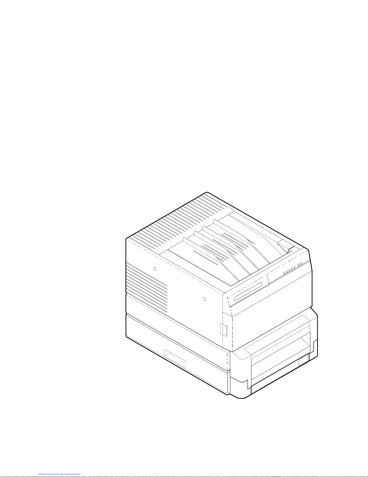
Phaser 200i
Figure 1-1. The DECcolorwr iter 1000 (show n with the Low er Tray
Assembly)
Service Manual 1-1
8699-01

1 General Information
DECcolorwriter 1000
DECcolorwr iter 1000 is an Adobe PostScript Level 2, two page-per-minute, color
thermal-wax transfer printer. Besides PostScript, it also supports the Hewlett
Packard-Graphics Language (HP-GL) printer language. DECcolorwriter 1000 prints at
an addressability of 300 dots-per-inch. The printer features a single paper tray w ith an
optional lower tray assembly which gives the printer a dual tray capability. (The Lower
Tray Assembly is sometimes referred to as the second feeder.) The printer prints images
on A- and A4-size paper and transparency film with 5 mm (0.2 in.) margins.
DECcolorwr iter 1000’s image processor is powered by a 16-MHz RISC processor and
features 8 Mbytes of RAM . The printer provides 17 standard printer fonts which can be
expanded to 39 fonts with the installation of an optional font m odule. In addition, the
DECcolorwriter 1000 supports a high-resolution 300 x 600 dots-per-inch printing mode.
For host image input, the controller also features a standard parallel port, an RS-232
serial port and a LocalTalk port.
Plain-paper printing
The DECcolorw riter 1000 prints on a specially coated paper with a very smooth, even
surface, optimized for wax-transfer pri nt ing. The printers can also print on ordinary
Bond paper, using a special 4-pass plain-paper transfer roll. During printing, a special
primer coating is applied to the paper in its first pass past the thermal head. The coating
is applied only to the portions of the paper where yellow, magenta and cyan wax will be
applied in the following passes. The coating supplies a smooth, fl at surface for the wax
to adhere to. Because of the extra pass required for printing on plain-paper and the fact
that the drum moves in a slower, half-step mode while placing the precoat on the paper,
plain-paper printing times are slightly longer than printi ng on coated paper with the
3-pass, 3-Color Transfer Roll.
1-2 DECcolorwriter 1000
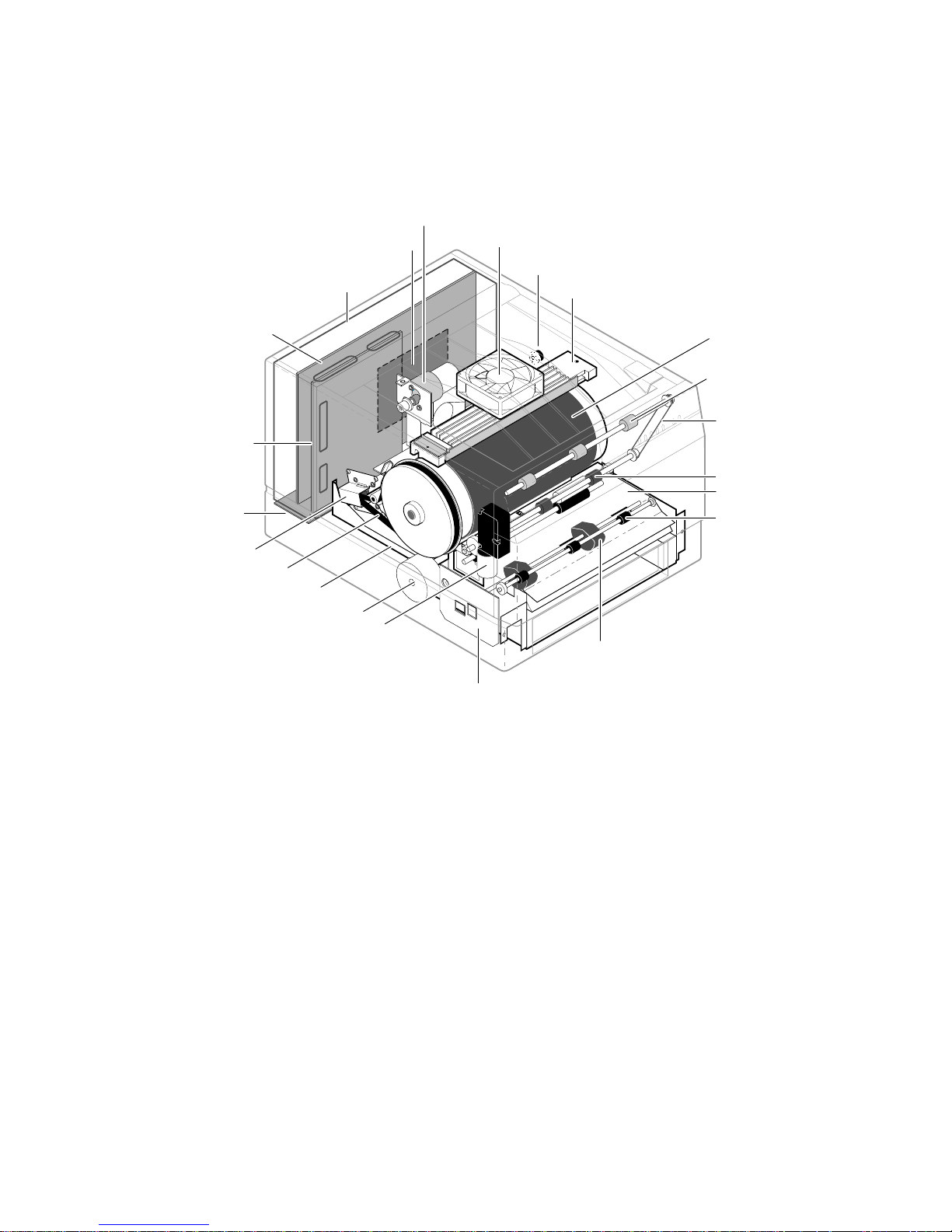
Print engine assemblies
Thermal head lift motor
I/O board
Card cage
General Informatio n 1
Thermal head fan
Torque limiter
Thermal head
Image processor
board
Engine control board
Interconnect board
Drum motor
Drum belt
Power supply
Paper-feed motor
Transfer roll take-up motor
Pick roller
Print-feed circuit board
Figure 1-2. Internal features of the DECcolorwriter 1000 pri nt engin e
Drum
Upper exit roller
Exit roller belt
Lower exit roller
Paper-feed module
Feed roller
8699-02B
Service Manual 1-3
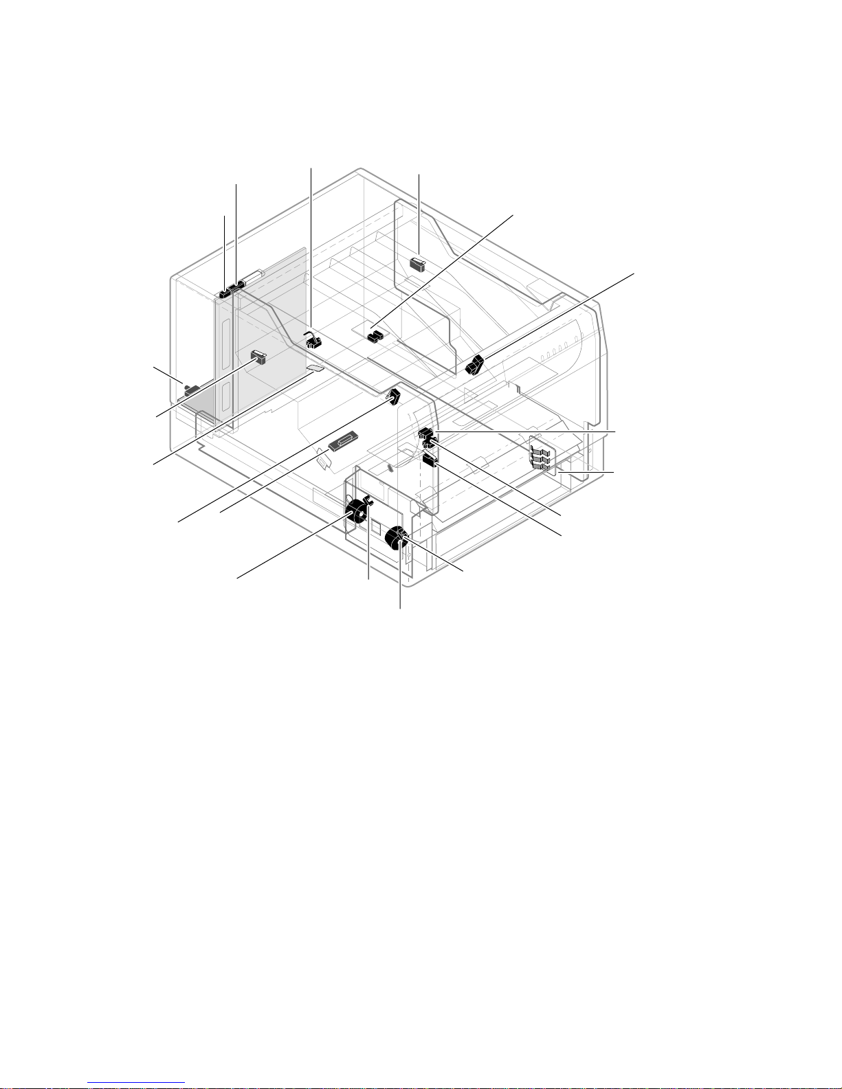
1 General Information
TEST
button
Transfer roll
core sensor
(left)
Transfer roll
mark sensor
Top-cover-
open sensor
DIP Switch 1
DIP Switch 2
Paper clamp
sensor
Transfer-roll-
low sensor
Transfer roll
core sensor
(right)
Thermal head position
sensors (2) -- mounted on top cover
Drum-home-
position sensor
Paper-pass
sensor (2)
Tray
sensors (3)
Paper-exit sensor
Front-cover-open sensor
Aligning roller
solenoid
Paper-pass
sensor (1)
Paper-pick
solenoid
Paper-empty
sensor
Figure 1-3. Sensors and switches on the DECc olorw riter 1000 pri nt eng ine
8699-03B
1-4 DECcolorwriter 1000

General Informatio n 1
Combination sensors and their meanings
Combinations of sensors are used by the D ECcolorwriter 1000 to determine the type of
transfer roll and the type of media tray installed in the printers.
Transfer roll type sensing
The combinations of the two transfer roll core sensors “tell” the print engine what type of
transfer roll is installed. The length of the cores (long or short) actuate the switches.
Long cores close the switches, turning them o n.
Table 1-1. Transfer roll core sensor comb in atio ns
Left transfer
roll core
sensor
Closed Op en Plain Paper Transfer Roll
Open Open 3-Color Transfer Roll (for coated paper)
Closed Closed Black Transfer Roll (for coated paper)
Right transfer
roll core
sensor
Transfer roll type
Service Manual 1-5

1 General Information
Media tray type sensing
The combinations of the three tray sensors “tell” the Phaser 200e what type of paper tray
is installed. (The print engine does not detect the type of media installed in the tray; it
only detects the particular tray used with the media.) The tray sensors are located on the
right-side inter ior of the paper tray slot. Ther e are four different tray types:
n Letter Perforated Media. This tray is used for paper and transparency film
with the tear-off perforation. This extra-long media accounts for the portion
of the media held by the drum's paper clamp during printing (and therefore
cannot be printed upon.) After tearing off the perforated end of the print, the
result is a letter-size print in which the image is printed evenly to all four of
the paper’s edges. A slide switch on the side of the media tray lets you select
either paper or transparency film.
n Letter Plain Paper . This tray is sized for 8.5 x 11-inch plain paper. It is used
when printing with the Plain Paper Transfer Roll.
n A4 Perforated Media. This tray is used for the metric equival ent of the
Letter-size perforated media. A slide switch on the side of the media tray lets
you select either paper or transparenc y film.
n A4 Plain Paper. This tray is sized for 210 x 297-mm plain paper. It is used
when printing with the Plain Paper Transfer Roll.
Lower tray assembly. The identical sensor combination scheme is used to determine
the type of tray (referred to as the lower tr ay) installed in the Lowe r Tray Assembly.
(The Lower Tray Assembly i s sometimes referred to as the second feeder.)
Table 1-2. Tray switch sensor combi nati on s
Bottom
switch
Open Closed Open Letter – Perforated paper
Open Open Closed Letter – Perforated transparency film
Open Closed Closed Letter – Plain paper
Closed Open Open A4 – Perforated paper
Closed Open Closed A4 – Perforated transparency film
Closed Closed Closed A4 – Plain Paper
Middle
switch
Top switch Tray type
1-6 DECcolorwriter 1000
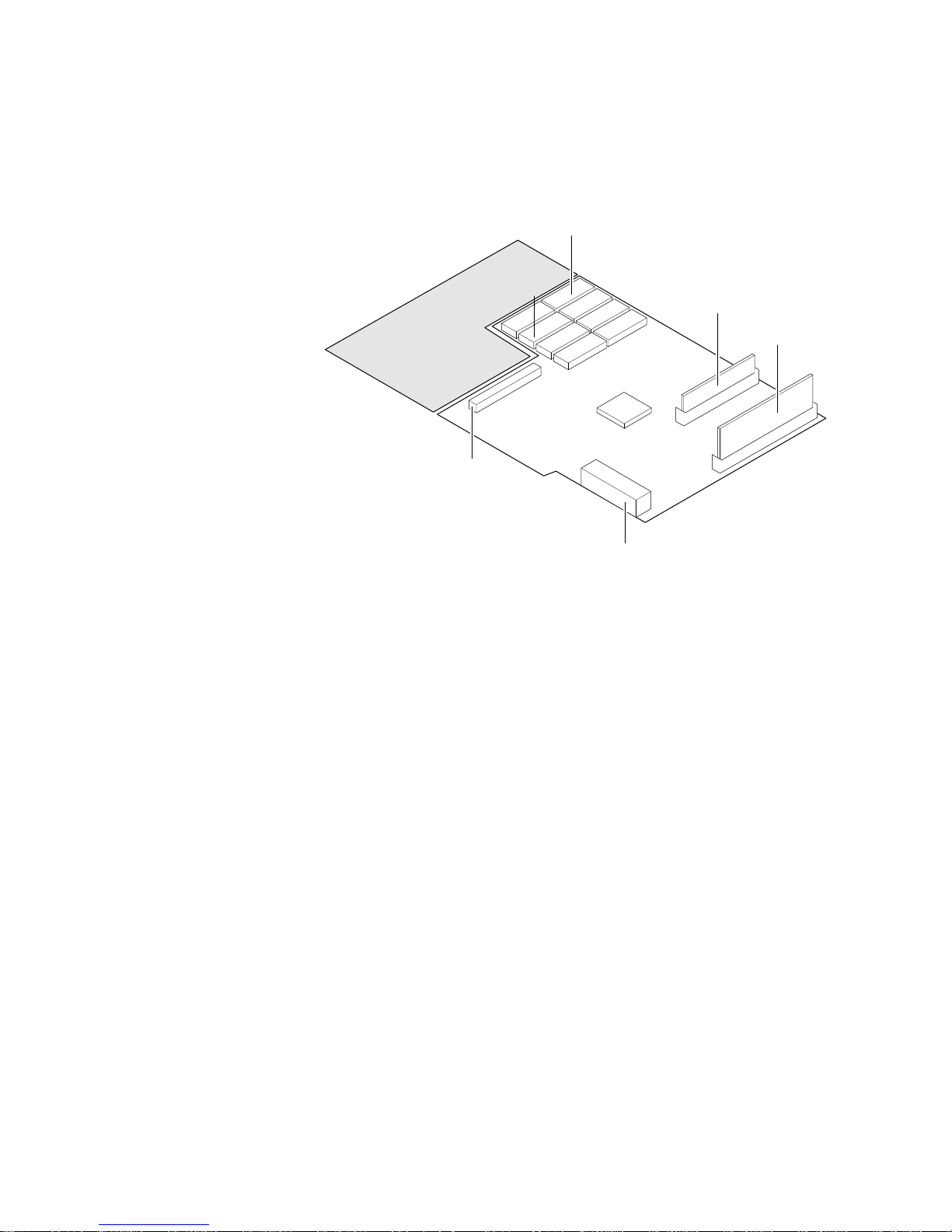
Image processor boards
General Informatio n 1
ROM
Font
SIMM
RAM
SIMM
J2
I/O connector
Interconnect board
connector
J14
J6
J1
Figure 1-4. Features of the DECcolor writer 1000 ima ge pro cess or
board
8699-05
Service Manual 1-7

1 General Information
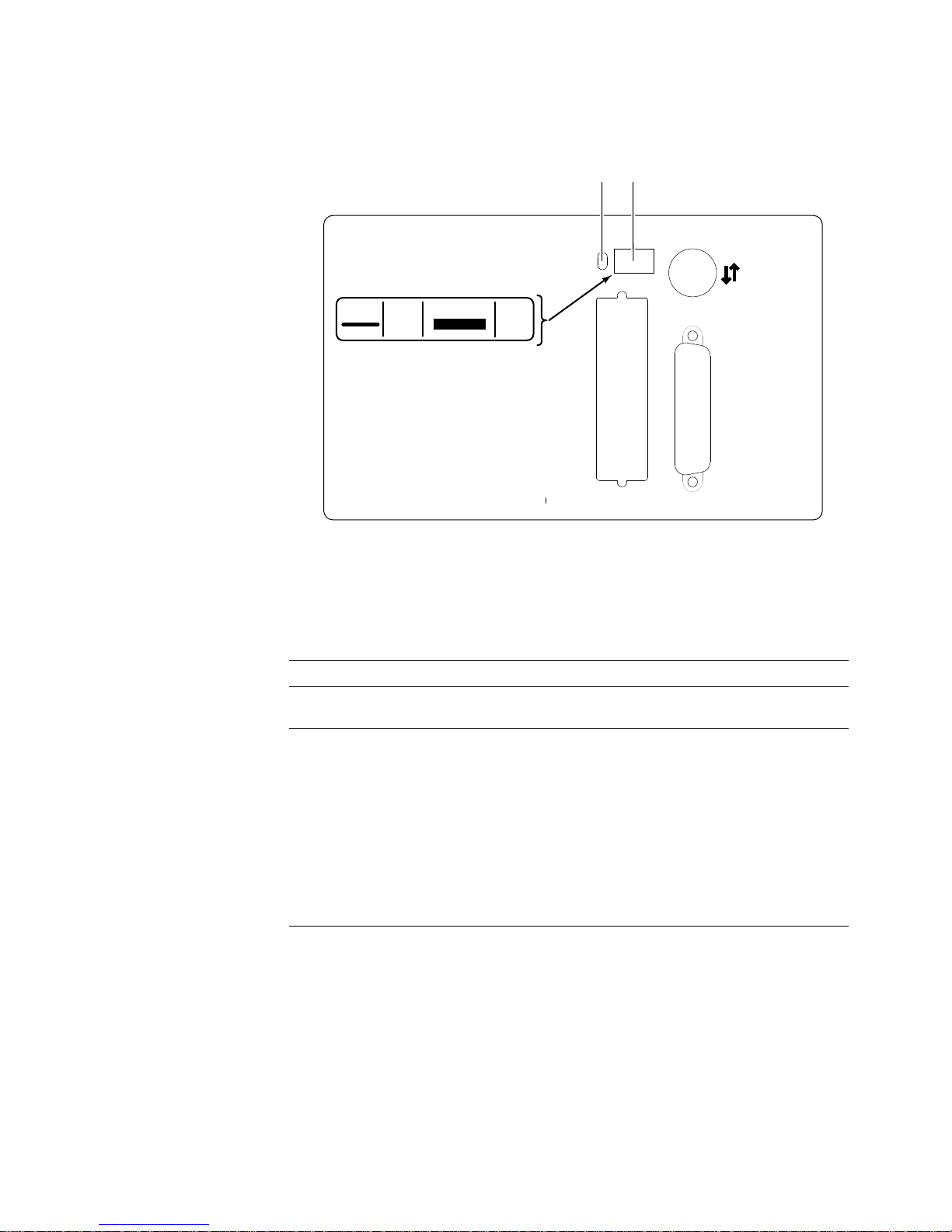
Rear panel
Connectors
The rear panel of the DECcolorwriter 1000 printer features the host interface connectors
to the printer. They include the following connector s:
n Standard parallel
n RS-232 serial
n LocalTalk
The DECcolorwriter 1000 rear panel also feature s DIP switches to control certain
aspects of the printers’ imaging. You can also use the DIP switches for controlli ng the
self-tests of the printers’ image processor board. Refer to the Section 6 topic “Image
processor self-diagnostics” on page 6-30.
Health LED
A health LED indicates the status of the printer.
n Blinking (at a steady rate): The printer is operating normally. The LED
blinks irregularly during diagnostics.
If a soft error occurs, the image processor board will operate, but in a reduced
capacity. Soft failures include failure of expansion memory SIMMs or any of
the interface ports. When a soft error occurs, the printer automatically prints
a start-up page listing the error.
n On or Off: A hard error condition has occurred that would keep the image
processor board from operati ng.
TEST button
The TEST button, located at the bottom right rear corner of the printer, has two
functions:
n Following normal power-up, pressing the TEST button for 5 seconds prints a
composite test pattern. Refer to Figure B-1 in Appendix B, Test Patterns for
a sample of the com posite test pattern.
n Pressi ng and holding the TEST button while you turn on the printer places
the printer in Servic e m o de.
1-8 DECcolorwriter 1000
General Informatio n 1
The following figure illustrate the re ar panel of the DECcolorwriter 1000.
Health
LED
Status
1
Reset
Run
2
**
34
On
Color Correction
Off
* See Below
Parallel
DECcolorwriter 1000
Figure 1-5. DECcolor wri ter 1000 rear panel
DIP switches
Serial
(RS-232)
LocalTalk®
8699-07
Table 1-3. DECcolorwriter 1000 rear panel DIP Switch es
Switches 220e
down
1(
) Normal operation
(
up
) Reset
2 through 4 Diagnostics modes, serial parameters fixed at 1200 baud. Vivid Blue,
Configuration page, NVRAM Reset, Demo pages
2 3 4
↓↓ ↓Normal power-up self tests
↑↓ ↓Fixed RS- 232 param eters
↓↑ ↓Used NVRAM-stored color correction
↑↑ ↓Service m ode
↓↓ ↑Configuration page/NVRAM reset
↑↓ ↑ Demo pages
↓↑ ↑ Verification mode
↑↑ ↑ No self tests
Service Manual 1-9
1 General Information
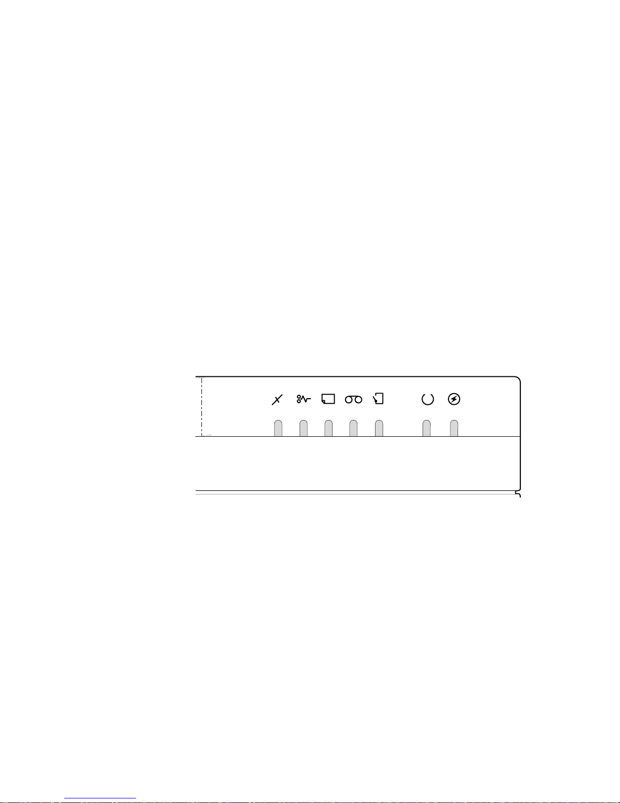
Front panel
The front panel consists of seven LEDs indicating the pr inter's normal operating status.
POWER: Illuminates to indicate that the power supply is generating +5 VDC.
READY: On indicates the printer is idle. Blinking indicates the printer is receiving and
processing data.
COVER: On indicates either the front or top cover is open.
TRANSFER ROLL (RIBBON): On indicates the transfer roll is low and will soon
need to be replaced. Blinking indicates the transfer r oll is empty.
MEDIA: On indicates the paper tray i s empty. Blinking (together with the JAM light)
indicates the wrong size paper is installed in the paper tray.
JAM: On indicates a jam has occurred inside the printer. Blinking indicates a
paper-pick error has occurred.
ERROR: On indicates a hardware engine error has occurred. Blinking indicates a data
processing error has oc curred with the image processor board.
ERROR JAM RIBBON COVER
Figure 1-6. DECcolorwriter 1000 front panel
READY
POWERMEDIA
1-10 DECcolorwriter 1000

Front panel LED service mode e rror cod es
Detected error conditions are displayed on the front panel as LED patterns. The
following table lists the service mode error codes which are displayed while the printer is
in service mode. (Service mode is explained in Chapter 9, “Checks and Adjustments.”)
These codes are mor e specific than the error codes displayed during normal operation
(see the previous topic “Rear panel). If an error occurs during normal operation, pressing
the rear panel TEST button causes the appropriate, and more specific, service mode error
code to be displayed on the front panel. The error codes listed below are explained in
greater detail in the Chapter 6 topic “Print engine error codes and their causes” on
page 6-19.
Table 1-4. Service mode error code summary
Front panel LEDs Hex codeError
o o o o o o Z 00 No error
o o o o o Z Z 01 Drum position error.
o o o o Z o Z 02 Thermal head temperature error.
o o o Z oo Z04 Top cover open error.
o o o Z o Z Z 05 Front cover open error.
o o o Z Z o Z 06 Strobe error.
o o o Z Z Z Z 07 Engine control board RAM error.
o o Z o o o Z 08 Engine control board ROM error.
o o Z o Z o Z 0A Interface error with image processor board.
o o Z Z o Z Z 0D Thermistor failure.
o o Z Z Z o Z 0E Thermal head lift error.
o o Z Z ZZ Z 0F Thermal head thermistor failure.
o Z o o o o Z 10 Transfer roll empty.
o Z o o o Z Z 11 Transfer roll low.
o Z o o ZZ Z12 Transfer roll jam.
o Z Z o o o Z 18 Transfer roll feed timer error.
Z o o o o o Z 20 Out of media.
Z o o o o Z Z 21 Tray not installed.
Z o o o Z o Z 22 Paper eject sensor failed to turn on.
o o o ZZZ 23 Paper-pass error / lower tray.
Z
o o Z oo Z24 Paper-pass error / upper tray.
Z
Z o o Z o Z Z 25 Paper-pass sensor 2 error.
Z o o Z Z o Z 26 Paper clamped error.
Z o o Z ZZ Z 27 Media size error.
Z o Z o o o Z 28 Paper eject sensor failed to turn off.
Z o Z o o Z Z 29 Paper-pass sensor 1 failed to turn off after
paper eject.
Z o Z o Z o Z 2A Paper-pass sensor 2 failed to turn off after
paper eject.
Z o Z o ZZ Z 2B Clamp timer error.
General Informatio n 1
o means LED off
Z means the POWER L ED which is always on
Z means LEDon
Service Manual 1-11

1 General Information
Specificatio ns
These specifications apply to the DECcolor wr ite r 1000 printer.
Table 1-5. Physi cal dim ensi on s
Dimensions Value
Height 28 cm. (11 ins.)
Width: 342 cm (13.4 ins.)
Depth: 42.5 cm (16.7 ins.)
Weight: Approximately 18 kgs (40 lbs). Print engine weight only; add
37 cm (14.5 ins.) with Lower Tray Assembly
26.4 kgs (12 lbs.) for Lower Tray Assembly. Shipping weight
is not to exceed 32 kgs (70 lbs).
Table 1-6. Printer cle aran c es
Clearances Value
Top: 45.7 cm (18 ins.)
Left: 10.2 cm (4 ins.)
Right: 10.2 cm (4 ins.)
Front: Unrestricted to replace trays and transfer rolls
Rear: 10.2 cm (4 ins.)
Bottom: No obstruction under printer that could block its cooling
vents.
Mounting surface
flatness:
Within 5 degrees of horizontal with all four feet in contact
with the surface.
1-12 DECcolorwriter 1000

General Informatio n 1
Table 1-7. Functi on al speci ficati on s
Characteristic Specification
Printing process Sequential surface t hermal transfer printing (thermal-wax
transfer).
Transfer rolls Wax-impregnated transfer rolls. The printer automatically
Addressability 300 dots-per-inch (horizontal and vertical).
Engine printing speed The time it takes from paper loading to paper ejecting a print:
Minimum printing
margins
senses the transfer roll type by the coding on the leading
edge of the yellow band.
3-Color Transfer Roll features sequential bands of yellow,
cyan, and magenta; 342 prints per roll.
A 4-pass Plain Paper Transfer Roll features sequential bands
of precoat, yellow, magenta and cyan; 214 prints per roll.
Black Transfer Roll features all black panels; 880 prints
per rol l.
The printer automatically senses the transfer roll type by the
size of the transfer roll cores.
3-Color transfer roll: about 30 seconds per print.
ColorCoat transfer roll: about 40 seconds per print.
Print times do not include image processing time by the
image processor which varies due to image complexity.
Perforated paper:
A- and A4-size: all sides, 5 mm (0.2 ins.).
Non-perforated paper
A- and A4-size: all sides, 5 mm (0.2 ins.) except the bottom,
which is 21 mm (0.8 ins.)
Service Manual 1-13

1 General Information
Table 1-8. Electrical specifications
Characteristic Specification
Primary line voltages 87 to 128 VAC (115 VAC nominal)
174 to 250 VAC (220 VAC nominal)
Input voltage range is switch-selectable.
Primary voltage
47 to 63 Hz
frequency range
Power consumption 235 watts at idle. (800 BTUs/hour) – Power consumption for
the printer will be somewhat higher due to image processor
electronics which draw power from the print engine.
Current rating 115 VAC configuration – 7 amp max./1 amp min.
220 VAC configuration – 7 amp max./1 amp min.
Primary voltage fusing 115 VAC configuration – 5 amp
220 VAC configuration – 5 amp
Fuses are not user-accessible.
Secondary voltages +5
V (4.95 ~ 5.05 V) — 10 A maximum
+12 V (11.2 ~ 12.6 V)
-12 V (115.5 ~ 12.5V)
+24 V (24.4 ~ 24.7V)
VH – thermal head voltage (V
high
– 26 ~ 27.4 V), (V
– 10.6 ~ 11.0)
low
RF emissions Both 115 and 220 VAC-configured instruments pass these
standards: FCC Part 15 Class B
VDE 0871/6.78 Class B
EN55022 (CISPR 22) Class B
VCCI (CISPR 22) Class B
1-14 DECcolorwriter 1000
 Loading...