

Digital Equipment DECbridge 90 Owner's Manual

DECbridge90
Owner’sManual
Order Number: EK-DEWGB-OM. B01
Revision/Update Information: This is a revised manual.
Digital Equipment Corporation
Maynard, Massachusetts

First Edition, April 1991
Second Edition, September 1992
The information in this document is subject to change without notice and should not be construed
as a commitment by Digital Equipment Corporation. Digital Equipment Corporation assumes no
responsibility for any errors that may appear in this document.
The software described in this document is furnished under a license and may be used or copied
only in accordance with the terms of such license.
No responsibility is assumed for the use or reliability of software on equipment that is not supplied
by Digital Equipment Corporation or its affiliated companies.
Restricted Rights: Use, duplication, or disclosure by the U.S. Government is subject to restrictions
as set forth in subparagraph (c) (1) (ii) of the Rights in Technical Data and Computer Software
clause at DFARS 252.227-7013.
© Digital Equipment Corporation 1991, 1992.
All Rights Reserved.
Printed in U.S.A.
FCC NOTICE: The equipment described in this manual generates, uses, and may emit radio
frequency energy. The equipment has been type tested and found to comply with the limits for
a Class A computing device pursuant to Subpart J of Part 15 of FCC Rules, which are designed
to provide reasonable protection against such radio frequency interference when operated in a
commercial environment. Operation of this equipment in a residential area may cause interference,
in which case the user at his own expense may be required to take measures to correct the
interference.
The following are trademarks of Digital Equipment Corporation: BI, DEC, DECbridge, DECconnect,
DECmcc, DECnet, DECserver, Digital, LAT, MicroVAX, ThinWire, ULTRIX, UNIBUS, VAX,
VAX–11/780, VAX–11/785, VAX 3600, VAX 3900, VAX 6000, VAX 6300, VAX 6400, VAX 9000,
VAXcluster, VAX DOCUMENT, VAXELN, VAXstation, VMS, VT, and the DIGITAL logo.
This document was prepared using VAX DOCUMENT, Version 2.0.

Contents
About This Manual. . . . . . . . . . . . . . . . . . . . . . . . . . . . . . . . . . . . . . vii
1 Overview
Features . . . . . . . . . . . . . . . . . . . . . . . . . . . . . . . . . . . . . . . . . . . . . 1–1
Description . . . . . . . . . . . . . . . . . . . . . . . . . . . . . . . . . . . . . . . . . . . 1–2
DECbridge 90 Front Panel Lights and Switches . . . . . . . . . . . . . . 1–3
2 Configuring the DECbridge 90
Supported Configurations . . . . . . . . . . . . . . . . . . . . . . . . . . . . . . . . 2–4
3 Installation
Power Supply . . . . . . . . . . . . . . . . . . . . . . . . . . . . . . . . . . . . . . . . . 3–1
Site Considerations . . . . . . . . . . . . . . . . . . . . . . . . . . . . . . . . . . . . 3–2
Standalone Installation . . . . . . . . . . . . . . . . . . . . . . . . . . . . . . . . . 3–2
Mount DECbridge 90 on a Wall . . . . . . . . . . . . . . . . . . . . . . . . 3–3
Make Connections for Standalone Installations . . . . . . . . . . . . 3–5
Work Group Connection . . . . . . . . . . . . . . . . . . . . . . . . . . . 3–7
Power Supply Connection . . . . . . . . . . . . . . . . . . . . . . . . . . 3–7
Backplane Installation . . . . . . . . . . . . . . . . . . . . . . . . . . . . . . . . . . 3–8
Install the DECbridge 90 in the DEChub 90 Backplane . . . . . 3–9
Make Connections for Backplane Installations . . . . . . . . . . . . 3–9
4 Managing the DECbridge 90
DECbridge 90 Operation . . . . . . . . . . . . . . . . . . . . . . . . . . . . . . . . 4–1
DECbridge 90 Functions . . . . . . . . . . . . . . . . . . . . . . . . . . . . . 4–2
Spanning Tree Algorithm . . . . . . . . . . . . . . . . . . . . . . . . . . . . . 4–3
Spanning Tree Algorithm Properties . . . . . . . . . . . . . . . . . . . . 4–3
MOP . . . . . . . . . . . . . . . . . . . . . . . . . . . . . . . . . . . . . . . . . . . . . 4–3
MOP Functions . . . . . . . . . . . . . . . . . . . . . . . . . . . . . . . . . . . . 4–3
iii

Accessing MOP from VMS Systems . . . . . . . . . . . . . . . . . . . . . 4–4
Accessing MOP from ULTRIX Systems . . . . . . . . . . . . . . . . . . 4–6
Console Carrier User Interface . . . . . . . . . . . . . . . . . . . . . . . . 4–6
Console Carrier Command Language . . . . . . . . . . . . . . . . . . . . . . . 4–7
Description of Command Parameters . . . . . . . . . . . . . . . . . . . . 4–9
Description of Commands . . . . . . . . . . . . . . . . . . . . . . . . . . . . 4–10
Protocol Filtering Examples . . . . . . . . . . . . . . . . . . . . . . . . . . . 4–17
Remote Bridge Management Software (RBMS) . . . . . . . . . . . . 4–19
Error Messages . . . . . . . . . . . . . . . . . . . . . . . . . . . . . . . . . . . . . . . 4–20
5 Troubleshooting
Customer Services Option . . . . . . . . . . . . . . . . . . . . . . . . . . . . . . . 5–5
A Specifications and Parts List
Parts List . . . . . . . . . . . . . . . . . . . . . . . . . . . . . . . . . . . . . . . . . . . . A–3
B Related Documentation
Ordering Information . . . . . . . . . . . . . . . . . . . . . . . . . . . . . . . . . . . B–1
Continental USA and Puerto Rico . . . . . . . . . . . . . . . . . . . . . . B–1
New Hampshire, Alaska, and Hawaii . . . . . . . . . . . . . . . . . . . B–2
Outside the USA and Puerto Rico . . . . . . . . . . . . . . . . . . . . . . B–2
Digital Personnel . . . . . . . . . . . . . . . . . . . . . . . . . . . . . . . . . . . B–2
Index
Figures
1–1 Sample DECbridge 90 Connection . . . . . . . . . . . . . . . . 1–3
1–2 Indicators and Connectors . . . . . . . . . . . . . . . . . . . . . . 1–4
2–1 DECbridge 90 Configured to ThinWire Backbone . . . . 2–2
2–2 DECbridge 90 Configured to AUI Backbone . . . . . . . . . 2–3
2–3 Work Group With More Than 200 Stations . . . . . . . . . 2–5
2–4 Redundant Connections . . . . . . . . . . . . . . . . . . . . . . . . 2–6
2–5 Bridges in Work Group . . . . . . . . . . . . . . . . . . . . . . . . 2–7
2–6 Multiple Bridges in a Work Group . . . . . . . . . . . . . . . . 2–8
3–1 Standalone Installation . . . . . . . . . . . . . . . . . . . . . . . . 3–3
3–2 Removing the Back Cover . . . . . . . . . . . . . . . . . . . . . . 3–4
iv

3–3 Connecting Transceiver Cables . . . . . . . . . . . . . . . . . . 3–6
3–4 Connecting to the Middle of a ThinWire Segment . . . . 3–7
3–5 Connecting to the End of a ThinWire Segment . . . . . . 3–7
3–6 Installing the DECbridge 90 into DEChub 90
Backplane Slot 8 . . . . . . . . . . . . . . . . . . . . . . . . . . . . . 3–8
Tables
4–1 Ethernet Circuit Names for Systems . . . . . . . . . . . . . . 4–5
4–2 Summary of DECbridge 90 Commands . . . . . . . . . . . . 4–7
4–3 Protocol Type Codes and Names . . . . . . . . . . . . . . . . . 4–17
4–4 DECbridge 90 Error Messages . . . . . . . . . . . . . . . . . . . 4–20
5–1 Activity Indicators (LEDs) . . . . . . . . . . . . . . . . . . . . . . 5–2
5–2 Simple Troubleshooting . . . . . . . . . . . . . . . . . . . . . . . . 5–4
A–1 Physical Dimensions . . . . . . . . . . . . . . . . . . . . . . . . . . A–1
A–2 Operating Environment . . . . . . . . . . . . . . . . . . . . . . . . A–2
A–3 Shipping Environment . . . . . . . . . . . . . . . . . . . . . . . . . A–2
A–4 Power Specifications . . . . . . . . . . . . . . . . . . . . . . . . . . . A–2
A–5 Standalone Installation Kit Contents . . . . . . . . . . . . . . A–3
A–6 DEChub 90 Backplane Installation Kit Contents . . . . . A–3
v


About This Manual
This manual provides an overview of the DECbridge 90 unit and describes how
to configure, install, operate, manage, and troubleshoot the DECbridge 90. This
manual also provides the specifications and lists the related documentation for
the DECbridge 90.
In this manual, the DECbridge 90 unit may be referred to as the DECbridge 90,
work group bridge, bridge, or WGB.
Organization
This manual has five chapters and two appendices.
Chapter Description
1 Provides an overview of the DECbridge 90, including features,
description of front panel indicators, and configurations.
2 Provides configuration rules for the DECbridge 90.
3 Describes how to install the DECbridge 90.
4 Describes how to manage the DECbridge 90 through the
Maintenance Operations Protocol (MOP) or Network Control
Program (NCP).
5 Describes how to troubleshoot the DECbridge 90.
Appendix A Describes the physical dimensions; the environmental,
electrical, and power specifications; and provides a parts
list.
Appendix B Provides a list of related documentation and ordering
information.
vii

Conventions
The following conventions are used in this manual:
Convention Meaning
Note Provides general information.
boldface type Boldface type in examples indicates user input. For example:
DECbridge>
parameters Parameters are italicized. For example:
SHOW PORT slot number
[ ] Characters within brackets represent optional parameters. For
example:
SHOW PORT [hub number, slot number]
SET PROTOCOL
viii

1
Overview
The DECbridge 90 unit offers a reliable, high-performance, easy-to-install means
of connecting two local area networks (LANs). Configured as a standalone unit
or in the DEChub 90 backplane, the DECbridge 90 provides greater network
reliability and efficiency by allowing the local area network to be partitioned into
a number of smaller LANs.
Features
The following list summarizes the main features of the DECbridge 90:
• Easy-to-use
• Plug-and-go installation
• Activity LEDs for easy diagnosis
• Small size
• Rack-mountable in DEChub 90
backplane
• Frame filtering and frame forwarding
at full network throughput
• Protocol filtering
• Support of spanning tree algorithm
• Management through Maintenance
Operations Protocol (MOP) console
carrier
• Support of Remote Bridge Management
Software (RBMS)
• ThinWire and 15-pin AUI Ethernet
interfaces
Overview 1–1

Description
The DECbridge 90 is a specialized LAN device that connects two Ethernet or
IEEE 802.3 LANs to form a single extended local area network (Figure 1–1).
One LAN, referred to as the backbone, can consist of an unrestricted number of
stations. The other LAN, referred to as the work group, is usually the smaller
of the two LANs and is optimized for LANs of fewer than 200 stations. When the
work group consists of fewer than 200 stations, the DECbridge 90 automatically
prevents unnecessary traffic from being transmitted from one LAN to the other.
When there are more than 200 stations in the work group, the DECbridge 90
enters flood mode, which reduces the effectiveness of the traffic isolation,
but ensures full connectivity across the bridge. (Refer to Chapter 4 for more
information about flood mode.)
The DECbridge 90 provides the network manager with additional control over
traffic distribution through protocol filtering and repeater management features.
All stations connected within the extended LAN communicate with one another
as if they were all on the same LAN. The connected LANs will work in networks
using equipment designed to be compatible with the Ethernet or IEEE 802.3
standards. The DECbridge 90 connects to the work group using a ThinWire
(10Base2) integral transceiver. The backbone connections are made through a
15-pin AUI Ethernet (10Base5) interface.
Figure 1–1 shows a sample DECbridge 90 connection.
1–2 Overview
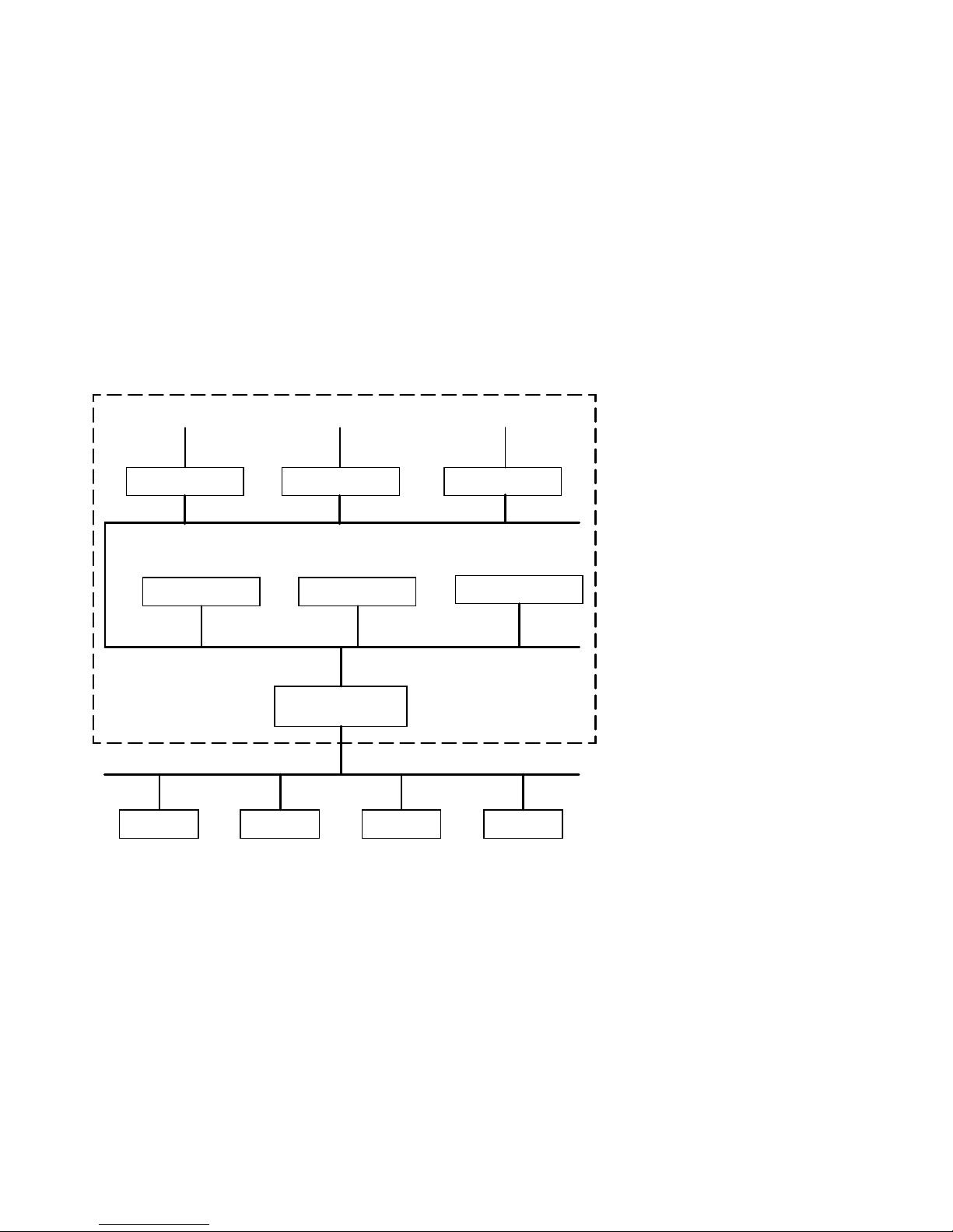
Figure 1–1 Sample DECbridge 90 Connection
Workstations
DECrepeater 90C
Workstation
Work Group
Computer
Workstations
DECrepeater 90T
Workstation
Work Group
DECbridge 90/90FL
Work Group Bridge
Ethernet
Computer Computer
Backbone
ThinWire
Terminals
DECserver 90L
Personal Computer
Segment
Server
LJ-02073-TI0
DECbridge 90 Front Panel Lights and Switches
The front panel of the DECbridge 90 contains several indicator lights and two
switches (Figure 1–2). The lights (LEDs) indicate the status of the DECbridge 90.
One of the switches is used to select ThinWire or AUI connection; the other
switch is used to reset the DECbridge 90 password. When you push the reset
button, any existing password is nullified and the DECbridge 90 is accessible
without a password until you define a new password. For an explanation of the
DEFINE BRIDGE PASSWORD command, refer to the Description of Commands
section in Chapter 4.
Overview 1–3

Figure 1–2 shows the DECbridge 90 indicators and connectors.
Figure 1–2 Indicators and Connectors
14
1
2
3
4
5
6
15
7
8
9
10
11
12
13
16
17
LJ-00067-TI0
DC OK Indicator - (Green) Turns on when power supply is providing
power to the bridge.
System OK Indicator - (Green) Turns on when bridge is powered up and
reset and has successfully completed self-test.
1–4 Overview
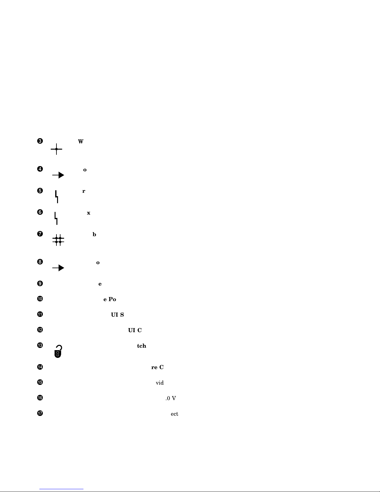
Work Group Port OK Indicator - (Green) Turns on when bridge is
powered up and reset and has successfully completed work group port
self-test. Will turn off whenever a fault is detected on the port; turns on
when the fault has been cleared.
Work Group Port Activity Indicator - (Green) Blinks when the LAN
connected to the work group port is receiving messages; does not blink
when transmitting messages.
Bridge Forwarding State - (Yellow) Turns on when bridge is not
forwarding messages. Turns on for a short period of time during power
1
up. Remains off during normal operation.
Maximum Work Group Size Exceeded Indicator - (Yellow) Turns on
when the recommended maximum size (200) of the work group has been
2
exceeded.
Backbone Port OK Indicator - (Green) Turns on when the bridge is
powered up and reset and has successfully completed backbone port selftest. Will turn off whenever a fault is detected on the port; turns on when
the fault has been cleared.
Backbone Port Activity Indicator - (Green) Blinks when there is
received activity on the LAN connected to the backbone port; does not blink
for transmitted messages.
Ethernet Address - Unique physical address of the bridge, comprised of
six 2-digit hexadecimal numbers.
Backbone Port ThinWire Connector - Provides ThinWire connection to
backbone port of the DECbridge 90.
ThinWire/AUI Selector - Selects ThinWire or AUI connection to the
backbone.
Backbone Port AUI Connector - Provides AUI connection to the
backbone port of the DECbridge 90.
Password Reset Switch - Nullifies the password for the DECbridge 90.
The bridge is accessible without a password until a new password is
defined.
Work Group Port ThinWire Connector - Provides ThinWire connection
to the work group port of the DECbridge 90.
Backplane Connector - Provides work group network connection to the
DECbridge 90 when it is installed in the DEChub backplane.
Power Connector - Provides +5.0 V and +12.0 V from the DECbridge 90
power supply (standalone) or the DEChub 90 power supply (mounted).
Cover - Covers the backplane connector and mounting assembly.
Overview 1–5


2
Configuring the DECbridge 90
The DECbridge 90 unit has several configuration rules and guidelines that must
be followed during installation and use.
Each LAN connected by the DECbridge 90 is required to be an Ethernet or
IEEE 802.3 compliant CSMA/CD LAN. The backbone port of the DECbridge 90
provides both ThinWire Ethernet (10Base2) and AUI (10Base5) connections,
as shown in Figure 2–1 and Figure 2–2. The work group port provides only a
ThinWire Ethernet (10Base2) connection.
Figure 2–1 shows the DECbridge 90 configured to a ThinWire backbone.
Configuring the DECbridge 90 2–1
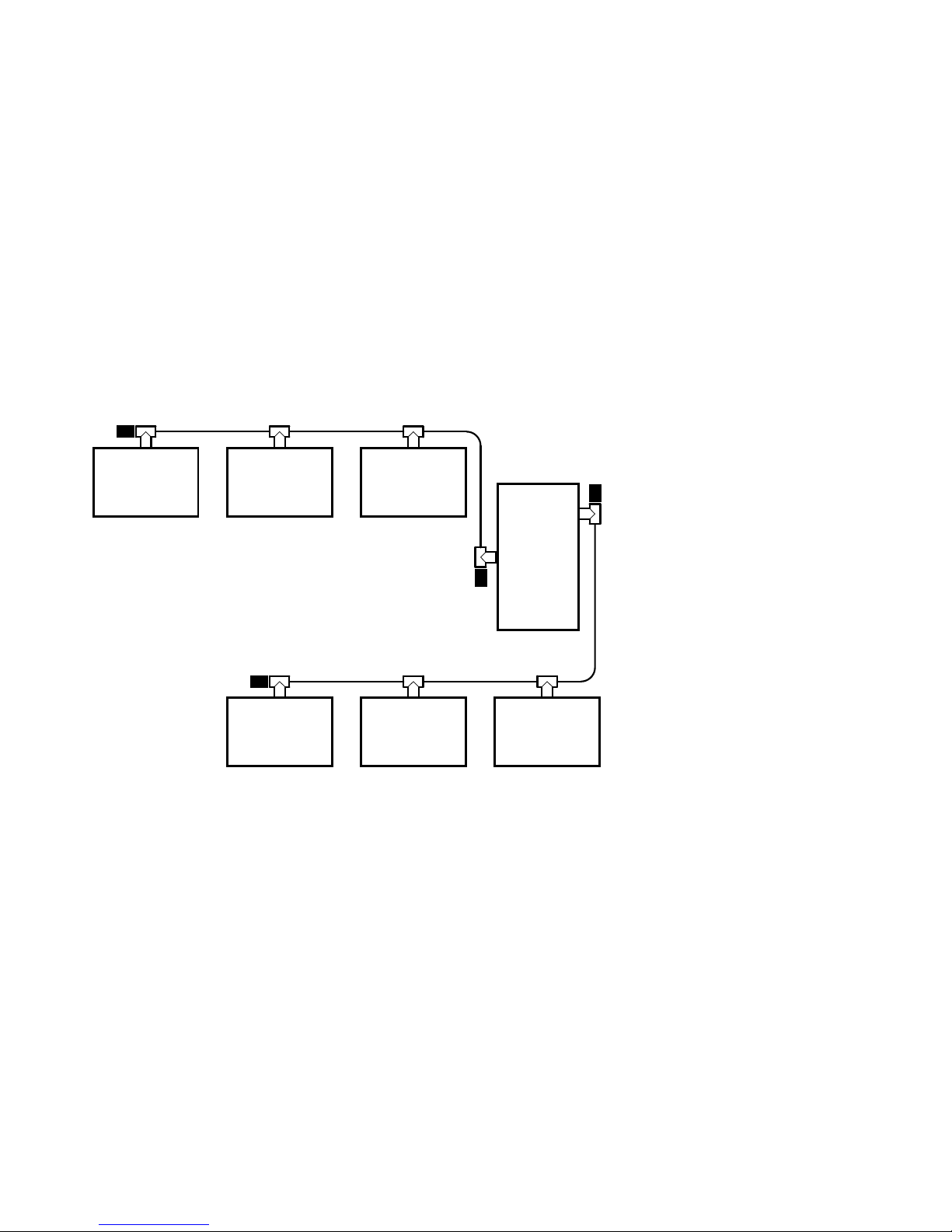
Figure 2–1 DECbridge 90 Configured to ThinWire Backbone
50-ohm
Terminator
System System System
Backbone
50-ohm
Terminator
Backbone Port
Thinwire Connection
50-ohm
Terminator
50-ohm
Terminator
System System System
Work
Group
Bridge
LJ-00247-TI0
2–2 Configuring the DECbridge 90
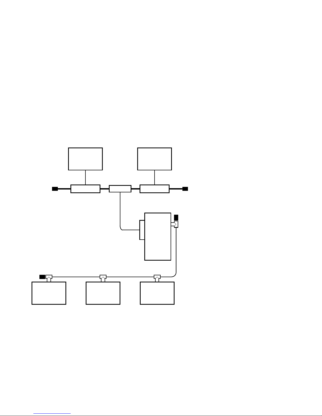
Figure 2–2 shows the DECbridge 90 configured to an AUI backbone.
Figure 2–2 DECbridge 90 Configured to AUI Backbone
System System
50-ohm
Terminator
50-ohm
Terminator
System
Transceiver Transceiver
System System
H4005
AUI
Connector
Work
Group
Bridge
50-ohm
Terminator
T-Connector
with Terminator
LJ-00244-TI0
Configuring the DECbridge 90 2–3

Supported Configurations
There are several reasons to configure bridges into an extended LAN:
• To connect different media types.
• To extend the range of the LAN. (For example, to attach a DEChub 90 to an
AUI backbone.)
Cable length and repeater configuration rules are considered separately in
each LAN.
• To control traffic by protocol type, by separating the LAN into networks for
selected protocols. (For example, to keep VAXcluster traffic confined within a
work group.)
• To automatically control traffic by keeping messages between stations on the
same LAN from being retransmitted on the other LAN.
The following network configurations may require special consideration:
• Work group size
To automatically isolate traffic, the work group should consist of less than 200
stations. When the number of stations in a work group exceeds 200, the Work
Group Size Exceeded light will come on indicating that flood mode is enabled
(indicator light number 6 shown in Figure 1-2). Refer to Chapter 4 for further
information about flood mode.
To avoid enabling flood mode when a work group consists of more than
200 stations, separate the work group into smaller groups of less than 200
stations each with its own DECbridge 90.
2–4 Configuring the DECbridge 90
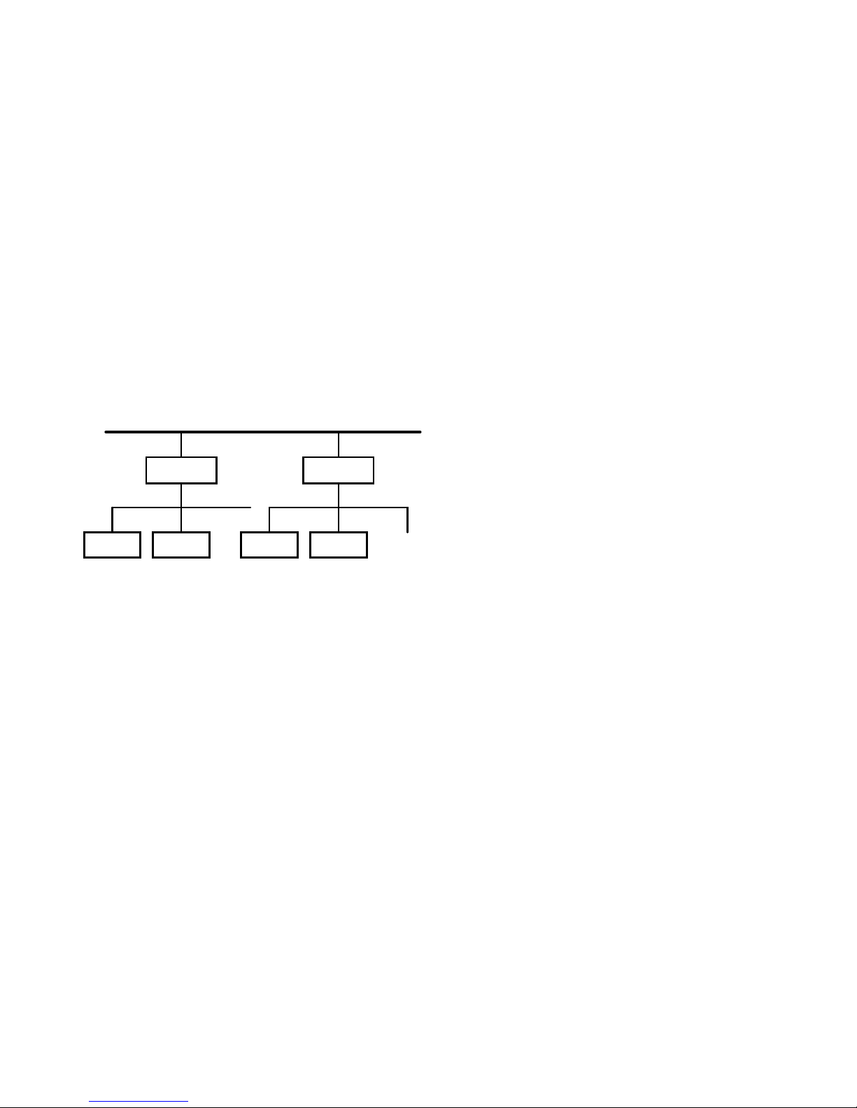
Figure 2–3 shows a configuration for a work group with more than 200
stations.
Figure 2–3 Work Group With More Than 200 Stations
Ethernet Backbone
WGB
System System
If there are more than 200 stations in a work group,
separate into two work groups.
System System
WGB
Work Group
< 200
Stations
LJ-02229-TI0
• Redundant connections to the backbone
If two DECbridge 90 units are configured into a redundant connection to the
backbone, the spanning tree algorithm will allow only one bridge to forward
traffic at a time. However, if a failure occurs in the backbone that causes the
connection to be separated into two LANs, the spanning tree may reconfigure
to pass all backbone traffic through your work group. When this occurs, the
work group side of the bridge may see more than 200 stations and enter flood
mode.
Configuring the DECbridge 90 2–5

Figure 2–4 shows redundant connections to the backbone.
Figure 2–4 Redundant Connections
Ethernet Backbone
WGB
Work Group
System System System
Parallel configurations.
Bridge
LJ-02232-TI0
• Bridges in the work group
If there are additional bridges on the work group side of the DECbridge 90,
be sure to count the stations on all LANs in the work group against the 200station limit and count each bridge as two against the total. In addition, if
any of these bridges lead back to the backbone, the redundant connection may
lead to spanning trees that exceed 200 stations on the work group side of the
DECbridge 90.
2–6 Configuring the DECbridge 90
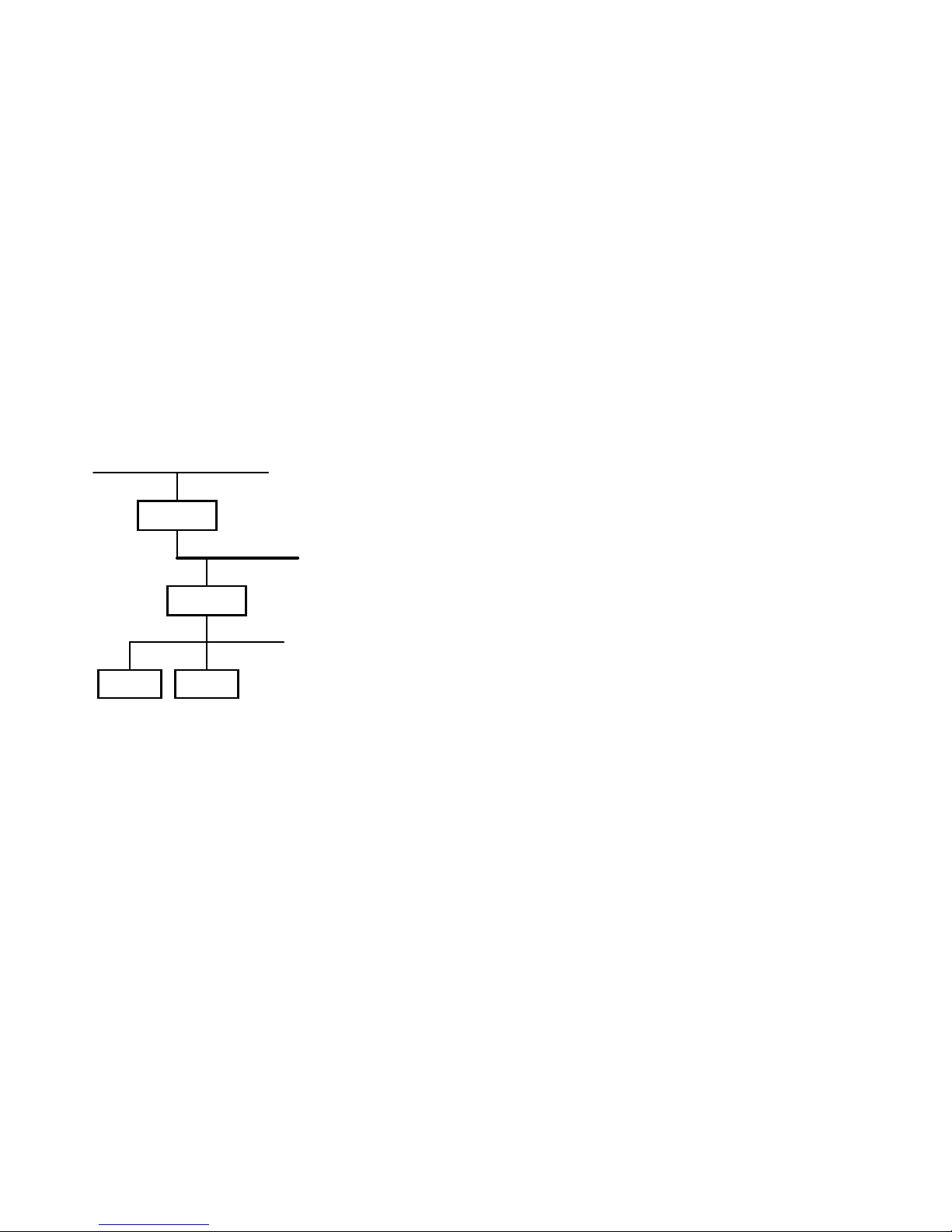
Figure 2–5 shows bridges in the work group.
Figure 2–5 Bridges in Work Group
Work Group
WGB
Backbone
WGB
Work Group
System System
Bridge in work group.
LJ-02233-TI0
• Number of bridges
The number of bridges between any two stations is limited to seven or less.
This guideline for networks with typical packet traffic loading is a compromise
of the many different protocols offered and used on Ethernet and IEEE 802.3
LANs.
Configuring the DECbridge 90 2–7
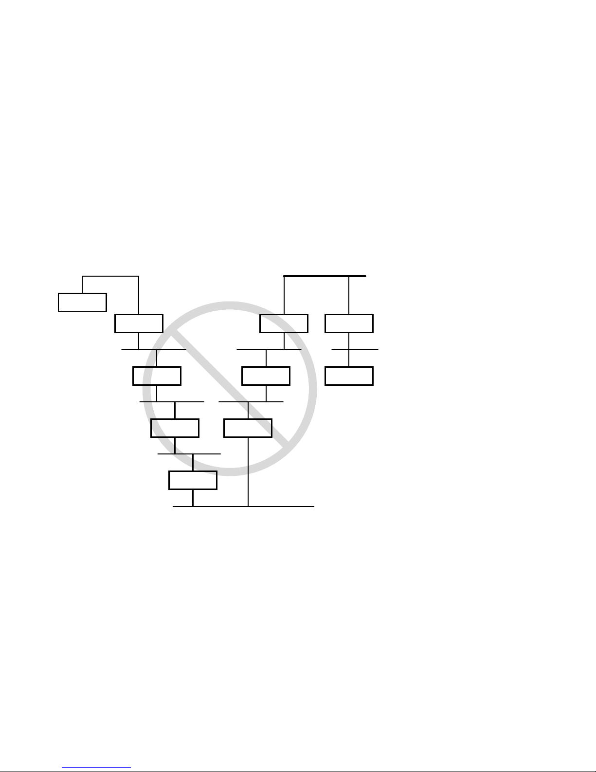
Figure 2–6 shows multiple bridges in the work group.
Figure 2–6 Multiple Bridges in a Work Group
Station
Ethernet Backbone
Bridge
Bridge
Bridge
Bridge
Bridge
Bridge
More than seven bridges between stations
on the Network.
Bridge
LJ-02236-TI0
WGB
Station
2–8 Configuring the DECbridge 90
 Loading...