

Digital Equipment 300 Series AXP, DEC 3000 Service Manual

DEC3000
Model300 Series AXP
ServiceGuide
Order Number: EK–PELCN–SV. B01
Digital Equipment Corporation, Maynard, MA

Second Printing, January, 1994
The information in this document is subject to change
without notice and should not be construed as a
commitment by Digital Equipment Corporation. Digital
Equipment Corporation assumes no responsibility for any
errors that may appear in this document.
© Digital Equipment Corporation 1994.
All Rights Reserved.
Printed in U.S.A.
The following are trademarks of Digital Equipment
Corporation: AXP, Alpha AXP, DEC, DEC PHIGS,
DECchip, DECnet, DECwindows, Digital, OpenVMS,
RX, RZ, ThinWire, TURBOchannel, VAX DOCUMENT, and
the DIGITAL logo.
Open Software Foundation is a trademark of, and Motif,
OSF, OSF/1 and OSF/Motif are registered trademarks of
the Open Software Foundation, Inc. CD is a trademark of
Data General Corporation; ISDN is a registered trademark
of Fujitsu Network Switching of America; MIPS is a
trademark of MIPS Computer Systems, Inc.; PostScript is a
registered trademark of Adobe Systems Incorporated.
All other trademarks and registered trademarks are the
property of their respective holders.
FCC NOTICE: This equipment has been tested and found
to comply with the limits for a Class A digital device,
pursuant to Part 15 of the FCC Rules. These limits
are designed to provide reasonable protection against
harmful interference when the equipment is operated in a
commercial environment. This equipment generates, uses,
and can radiate radio frequency energy and, if not installed
and used in accordance with the instruction manual,
may cause harmful interference to radio communications.
Operation of this equipment in a residential area is likely
to cause harmful interference, in which case users will be
required to correct the interference at their own expense.
S2438
This document was prepared using VAX DOCUMENT
Version 2.1.

Contents
Preface ........................ ix
1 Spare Parts List and 3D View of
System
Field Replaceable Units (FRU) ......... 1–1
Removing System Components ......... 1–3
Opening and Closing the System ....... 1–7
2 Using Console Commands
Overview ........................ 2–1
Console Mode Definition ........... 2–2
When Console Mode Is Used ........ 2–2
Program Mode Definition ........... 2–2
Console Mode Keys and Control
Characters . . ................... 2–2
Diagnostic Environments ........... 2–4
BOOT .......................... 2–6
CONTINUE . . . ................... 2–7
DEPOSIT........................ 2–8
EXAMINE ....................... 2–9
HALT .......................... 2–10
HELP .......................... 2–10
INITIALIZE . . . ................... 2–11
LOGIN ......................... 2–11
REPEAT ........................ 2–12
SET ........................... 2–12
SHOW .......................... 2–13
START ......................... 2–13
TEST .......................... 2–14
iii

3 LED Codes and Error and Status
Messages
Serial ROM Information ............. 3–2
Serial ROM LED Codes . . . ......... 3–2
Serial ROM Output Screen Displays . . . 3–5
Successful Completion of SROM
Initialization and Test Code ......... 3–5
Example Error Reports . . . ......... 3–5
Console Information ................ 3–7
Console LED Codes ............... 3–7
Console Error Messages . . . ......... 3–8
Console Halt Messages . . . ......... 3–9
TURBOchannel ASIC and CORE I/O ASIC
Information ...................... 3–10
TURBOchannel ASIC and CORE I/O
ASIC LED Codes ................ 3–10
TURBOchannel ASIC and CORE I/O
ASIC Diagnostic Error Codes ........ 3–11
TURBOchannel ASIC and CORE I/O
Status and Error Messages ......... 3–12
CXT Information . . ................. 3–14
CXT LED Codes ................. 3–14
CXT Diagnostic Error Codes ......... 3–14
ISDN Information . ................. 3–18
ISDN LED Codes ................ 3–18
ISDN Diagnostic Error Codes ........ 3–18
ISDN Diagnostic Status and Error
Messages ...................... 3–20
Memory Information ................ 3–22
Memory LED Codes .............. 3–22
Memory Diagnostic Error Codes ...... 3–22
Memory Status Messages . . ......... 3–23
Memory Error Messages . . ......... 3–24
MIPS Emulator Information . . ......... 3–25
MIPS Emulator LED Codes ......... 3–25
MIPS Emulator Error Messages ...... 3–25
NI Information . . . ................. 3–26
NI LED Codes . ................. 3–26
NI Diagnostic Error Codes . ......... 3–27
NI Status Messages .............. 3–29
iv

NI Error Messages ............... 3–30
SCC Information ................... 3–33
SCC LED Codes ................. 3–33
SCC Diagnostic Error Codes ......... 3–34
SCC Diagnostic Status Messages . . . . . 3–36
SCC Diagnostic Error Messages . . . . . . 3–36
SCSI Information .................. 3–39
SCSI LED Codes ................. 3–39
SCSI Diagnostic Error Codes ........ 3–40
SCSI Diagnostic Status Messages . . . . . 3–41
SCSI Error Messages . . ........... 3–41
TOY/NVR Information ............... 3–48
TOY/NVR LED Codes . . ........... 3–48
TOY/NVR Diagnostic Error Codes . . . . . 3–49
TOY/NVR Diagnostic Status and Error
Messages . . . ................... 3–49
A Power Supply DC Output
Connections
Appendix Overview ................. A–1
Index
Figures
1–1 3D View of System
Components . . . ........... 1–5
1–2 Opening and Closing the
System ................. 1–8
Tables
1 Telephone Numbers of Digital
Support Centers ........... xiii
1–1 Modules ................. 1–1
1–2 Cables and Power Cords . . . . . 1–2
1–3 Accessories............... 1–2
1–4 Hardware ............... 1–2
1–5 SCSI Devices . . ........... 1–3
v

1–6 Loopbacks and SCSI
Terminator ............... 1–3
2–1 Supported Keys and Control
Characters ............... 2–3
3–1 Power-up LED Codes ........ 3–3
3–2 Console LED Codes ......... 3–7
3–3 Console Error Messages ...... 3–8
3–4 Console Halt Messages ...... 3–9
3–5 TURBOchannel and CORE I/O
LED Codes ............... 3–10
3–6 ASIC Error Codes . ......... 3–11
3–7 CXT LED Codes . . ......... 3–14
3–8 CXT Error Codes . ......... 3–15
3–9 ISDN LED Codes . ......... 3–18
3–10 ISDN Error Codes . ......... 3–19
3–11 Memory LED Codes ........ 3–22
3–12 Memory Error Codes ........ 3–23
3–13 Terms Used In Memory Error
Messages ................ 3–24
3–14 MIPS Emulator LED Codes . . . 3–25
3–15 NI LED Codes . . . ......... 3–26
3–16 NI Error Codes . . . ......... 3–27
3–17 Terms Used In NI Error
Messages ................ 3–32
3–18 SCC LED Codes . . ......... 3–33
3–19 SCC Error Codes . ......... 3–34
3–20 SCSI LED Codes . . ......... 3–39
3–21 SCSI Error Codes . ......... 3–40
3–22 Terms Used in SCSI Error
Messages ................ 3–44
3–23 SCSI Information Values ..... 3–45
3–24 TOY/NVR LED Codes ....... 3–48
3–25 TOY/NVR Error Codes....... 3–49
vi

A–1 DC Output Connections . . . . . . A–1
vii


Preface
About This Document
Purpose and Audience
This manual is a reference document for Digital
service personnel and Digital customers who perform
maintenance work on the DEC 3000 Model 300 Series
AXP systems.
How To Use This Guide
This DEC 3000 Model 300 Series AXP Service Guide
complements the DEC 3000 Model 300 Series AXP
Hardware Reference Guide that came with your
system.
For information on ... Refer to ...
Adding, removing and replacing
internal devices
Console commands with
examples
Console commands at a glance Chapter 2 in this guide
Password security DEC 3000 Model 300 Series
Alternate console device DEC 3000 Model 300 Series
Troubleshooting by visual
inspection
DEC 3000 Model 300 Series
AXP Hardware Reference Guide
DEC 3000 Model 300 Series
AXP Hardware Reference Guide
AXP Hardware Reference Guide
AXP Hardware Reference Guide
DEC 3000 Model 300 Series
AXP Hardware Reference Guide
ix

For information on ... Refer to ...
Advanced diagnostics, including:
Diagnostic display lights
Power-up problems
Error messages
FRU codes
Diagnostic tests
Field replaceable units (FRUs) Chapter 1 in this guide
System components (3-D view) Chapter 1 in this guide
LED codes, error and status
messages
DEC 3000 Model 300 Series
AXP Hardware Reference Guide
Chapter 3 in this guide
Organization of This Guide
This manual is composed of three chapters and one
appendix:
• Chapter 1 provides an overview illustration of
the DEC 3000 Model 300 Series AXP system,
and a list of replaceable units (FRUs) and part
numbers.
• Chapter 2 briefly describes system console
commands.
• Chapter 3 contains tables that list error codes
and error and status information.
• Appendix A contains power supply information.
x

Conventions Used In This Guide
This document uses the following conventions:
Convention Description
Return
UPPERCASE
lowercase
show
A key name is shown enclosed to indicate that you
press the named key on the keyboard.
The console program does not distinguish between
uppercase and lowercase characters in typed user
input. All examples in this guide show user input
in lowercase. All system output is in uppercase.
A word in this typeface indicates a command that
you must enter from the keyboard at the console
prompt
(>>>)
. For example,
boot
.
Note
There is an 80-character
limit on the input line.
Commands cannot be wrapped
or continued to a new line.
Use the abbreviated form
of a command so the whole
command can be entered on
one line.
Because of space restrictions in
this guide, command format
examples show commands
continued to a new line.
variable Lowercase italicized letters in commands indicate
[ ] The information contained within these brackets
{ } The information contained within these braces is
a variable value that you must provide. The value
must be an actual option like a number or logical
such as on/off. Example:
is optional. The brackets are not part of the
command syntax and should not be typed.
required. The braces are not part of the command
syntax and should not be typed.
>>> set language
3
xi

Convention Description
" " Quotation marks indicate a literal string. A
- Options/qualifiers are identified by a hyphen. The
Note Notes provide general information.
WARNING: Warnings contain information to prevent personal
CAUTION: Cautions provide information to prevent damage
!
command in lowercase surrounded by quotes will
not convert to uppercase and will be put on the
network as lowercase. For example,
-fi "test.sys"
letters.
hyphen indicates that additional information can
be, or in some cases must be, supplied on the
command line. The hyphen must be typed.
injury. Read these carefully.
to equipment or software. Read these carefully.
A number like this that appears in text
corresponds to a number in an illustration.
will remain in lowercase
>>> B esa0
Related Documentation
The following documents provide additional
information about the DEC 3000 Model 300 Series
AXP systems.
Titles Part Number
DEC 3000 Model 300 Series AXP Documentation
Kit
DEC 3000 Model 300 Series AXP Hardware
Reference Guide
DEC 3000 Model 300 Series AXP Setting Up
Your System
DEC 3000 Model 300 Series AXP Adding
Memory
DEC 3000 Model 300 Series AXP Adding an
Internal Fixed Disk Drive
DEC 3000 Model 300 Series AXP Adding a
Removable-Media Drive
DEC 3000 Model 300 Series AXP Service Kit EK–PELSV-DK
EK–D3L00–DK
EK–PELCN–OG
EK–PELHW–IC
EK–PELAM–IC
EK–PELAD–IC
EK–PELAF–IC
xii

Digital Support
Digital service representatives are available for
on-site support for warranty and service contract
customers. If you are not currently eligible to receive
this support but would like to become eligible, please
contact either a Digital Support Center listed in
Table 1, or your local Digital office.
Support Center Contact Numbers
Table 1 lists the Digital Support Center contact
numbers. If a number for your area is not listed
below, please contact your local Digital office for
assistance.
Table 1 Telephone Numbers of Digital Support
Centers
Country Telephone Number
United States 1-800-354-9000
Canada 1-800-267-5251
Canada (Quebec) 1-800-267-2603
United Kingdom [44]25659200
France [33]92955111
Germany [49]-(89)-95913218
Australia 009 252-277
Note
Any troubleshooting techniques described
in this guide do not identify all possible
problems, nor do the actions suggested
correct all problems.
xiii


1
Spare Parts List and 3D View of
System
Field Replaceable Units (FRU)
Table 1–1 (Modules), Table 1–2 (Cables and
Power Cords), Table 1–3 (Accessories), Table 1–4
(Hardware), Table 1–5 (SCSI Devices), and Table 1–6
(Loopbacks and SCSI Terminators), list recommended
spare parts and part numbers for Digital service
representatives.
Table 1–1 Modules
Part Number Description
54-21246-BA 16-megabyte memory module (MS16-BA)
54-21277-AA 32-megabyte memory module (MS16-DA)
54-22249-01 System module—Models 300/300X/300LX
54-22249-02 System module—Models 300L
54-22257-01 CPU module—Model 300
54-22257-02 CPU module—Model 300L
54-22257-03 CPU module—Model 300X
54-22257-04 CPU module—Model 300LX
H7887-AA Power supply
1–1

Field Replaceable Units (FRU)
Table1–2 Cables and Power Cords
Part Number Description
17-00442-15 Auxiliary power cord, monitor to system
17-02640-01 Keyboard/mouse extender cable
17-02641-02 SCSI cable (50-pin Honda to 50-pin Champ
17-02906-01 Monitor video cable
17-03192-02 Twisted-pair cable
17-08339-01 External power cord
DETTR-AA/AB 10BASE-T to 10BASE2 (UTP to ThinWire)
DETTR-BA/BB 10BASE-T to AUI (UTP to thickwire) cable
unit
connectors)
cable
Table1–3 Accessories
Part Number Description
VSXXX-GA Mouse
VSXXX-JA Audio headset
LK401-xx Standard keyboard (country-specific)
12-36175-01 Grounding wrist strap
Table1–4 Hardware
Part Number Description
70-28353-02 Top cover assembly
70-30851-01 Front bezel
1–2

Field Replaceable Units (FRU)
Table 1–5 SCSI Devices
Part Number Description
RZ25-EP 426 MB, 3.5-in SCSI disk drive
RZ25L-DP 535 MB, 3.5-in SCSI disk drive
RZ26-EP 1050 MB, 3.5-in SCSI disk drive
RZ26L-EP 1.05-gigabyte, 3.5-in SCSI disk drive
RZ28-EP 2.1-gigabyte, 3.5-in SCSI disk drive
RX26-FB Removable-media drive
Table 1–6 Loopbacks and SCSI Terminator
Part Number Description
29-24795-02 N525 position loopback for RS232 port
12-33626-01 Micro D-sub male SCSI terminator
12-35619-01 MJ8 loopback for ISDN port
Removing System Components
To remove a TURBOchannel option, disconnect the
power cord and the option.
To remove the CPU, a memory module, or the power
supply, disconnect the power cable and the module.
Before you replace the system module, remember to
swap the Ethernet ROM, that is, move the chip from
the failing system module to the replacement system
module. Detailed instructions for locating, removing
and replacing the Ethernet ROM are available in the
DEC 3000 Model 300 Series AXP Hardware Reference
Guide, part number EK–PELCN–OG.
1–3
Removing System Components
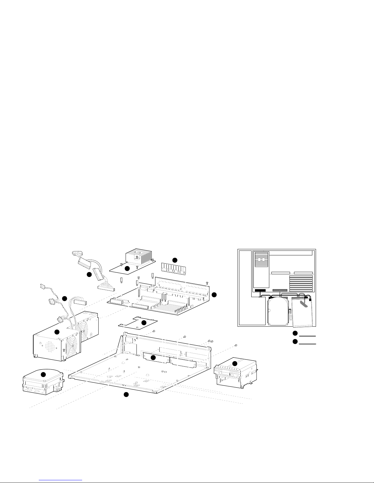
Figure 1–1 shows a 3-dimensional view of the
components in a DEC 3000 Model 300 Series
AXP system. To remove the system module in a
DEC 3000 Model 300 Series AXP system, disconnect
and remove each of the components (see Figure 1–1)
in the following order:
!
Power harness
"
SCSI cable
#
Removable-media device (or hard disk drive)
$
Hard disk drive
%
Memory
&
CPU module
'
TURBOchannel option slot filler panels
(
Power supply
)
System module
+>
Loose metal plate
+?
Bottom system enclosure
To remove a removable-media device#or a fixed
disk drive$, disconnect the power cord and SCSI
cable and then the device.
Refer to the DEC 3000 Model 300 Series
AXP Hardware Reference Guide, part number
EK–PELCN–OG, for detailed component installation
and removal instructions.
1–4
Removing System Components
Figure 1–1 3D View of System Components
6
2
5
1
10
8
7
4
11
9
1
Power:
2
SCSI:
3
MLO-010256
1–5

Removing System Components
1–6

Opening and Closing the System
Opening and Closing the System
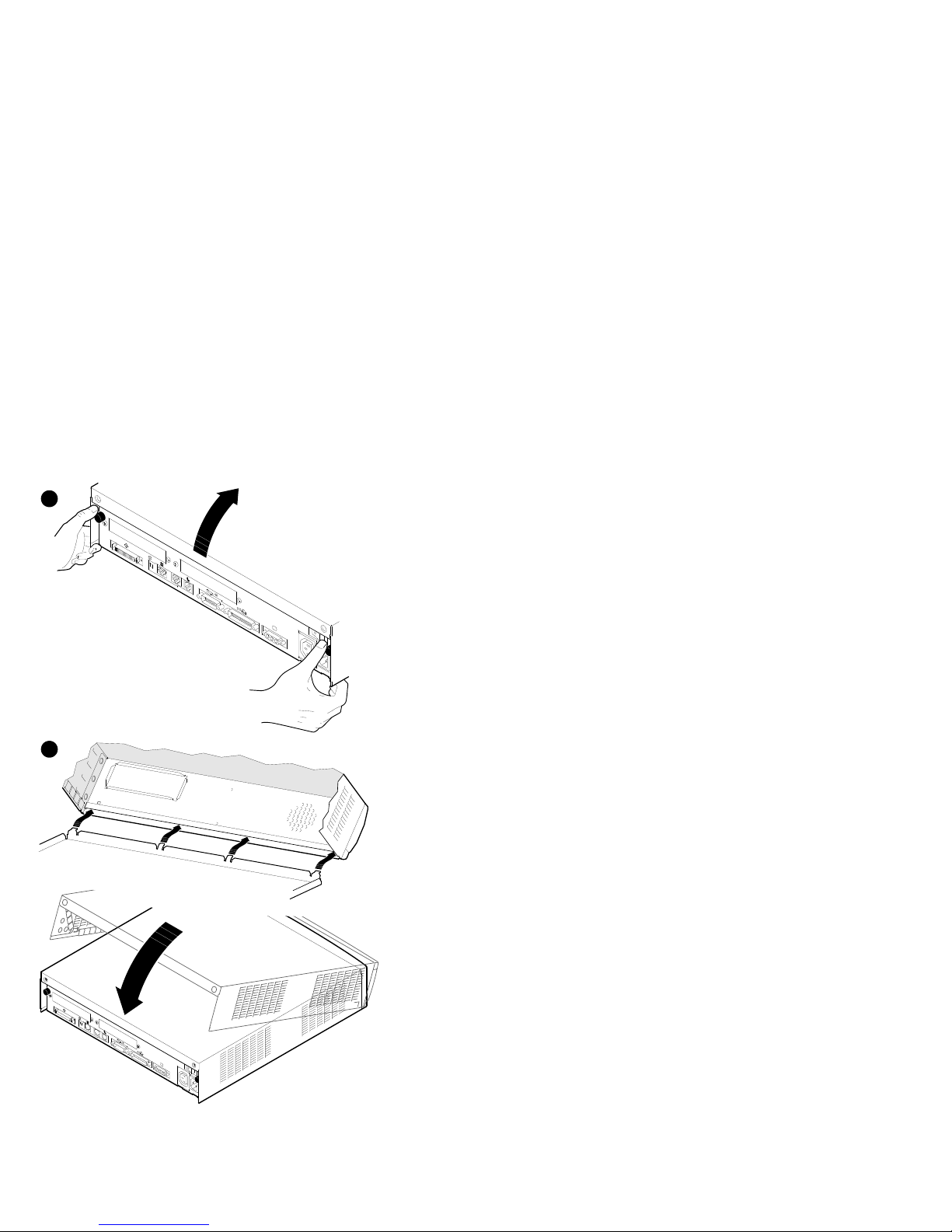
Refer to Figure 1–2 and follow these steps to open
and close a DEC 3000 Model 300 Series AXP system.
!
To open the system:
a. Remove the two Phillips screws on the right
and left back corners of the system unit
cover.
b. Place the system unit so that the back edge
extends over the edge of your table or desk.
c. Place your thumbs on the two black caps (see
Figure 1–2) on the back of the system unit,
and at the same time, place your fingers
under the cover’s bottom edge. Press down
with your thumbs while you press up against
the cover’s edge with your fingers.
"
To close the system:
a. Align the lip on the front inside edge of the
cover with the four tabs along the front edge
of the system unit (see Figure 1–2). Position
the cover so that the lip fits over the tabs.
b. Maintain a slight pressure on the front of the
cover as you lower it. Be sure the sides of
the cover fit over the outside of the bottom
enclosure.
c. Replace the two Phillips screws on the right
and left back corners of the system unit
cover.
1–7
Opening and Closing the System
Figure 1–2 Opening and Closing the System
1
0 1
ISDN
2
ISDN
1
1–8
MLO-010734

2
Using Console Commands
Overview
This chapter lists the DEC 3000 Model 300 Series
AXP console commands and explains the use of each
command.
The following console commands are covered in this
chapter:
boot login
continue repeat
deposit set
examine show
halt start
help test
initialize
Additionally, this chapter covers these topics:
• Definitions of console and program mode
• Three diagnostic environments
• Diagnostic examples associated with the
command
test
2–1

Overview
Console Mode Definition
In console mode, the system operates under the
control of the console subsystem, rather than the
operating system. All user input is passed to and
interpreted by the console subsystem.
Console mode is in effect when the system is turned
on and the operating system software has not been
started, or when the operating system has been shut
down.
When Console Mode Is Used
You interact directly with the console subsystem
under the following circumstances:
• Before booting the operating system software
• While setting environment variables
• When using the Firmware Update Utility
• When trying to identify and resolve system
problems or errors
Program Mode Definition
In program mode, the system and console are under
control of the operating system. All user input is
passed to the operating system. You cannot issue
console commands without returning to console mode.
Program mode is in effect when the system is turned
on and the operating system software has started. In
program mode, the user can manage the system, run
software applications, and perform network tasks.
Console Mode Keys and Control Characters
Control characters are entered by holding down
the key labeled Ctrl while pressing another key, for
Ctrl/C
example,
2–2
.
Overview
Table 2–1 lists the keys and control characters that
you can use while operating in console mode.
Table 2–1 Supported Keys and Control Characters
Key or
Control
Character Function
Return
<
Ctrl/C
Ctrl/O
Ctrl/S
Ctrl/Q
x
The Return key executes the command that you enter
at the console prompt.
The delete key deletes one character to the left of the
current command line position. On video terminals,
deleted characters will be erased from the screen.
On hardcopy terminals, deleted characters display
within a pair of backslash delimiters (\ \) as they are
deleted.
This character aborts the current command. This
command has no effect once control has been passed
from console mode to another program, such as the
operating system or a loadable diagnostic application.
This command appears as ^C on the screen.
This character suppresses output to the console
terminal until the
again.
This command appears as ^O on the screen.
This character suspends output to the console
terminal until you press
This character resumes the display that was
previously suspended by pressing
Ctrl/O
control character is pressed
Ctrl/Q
.
Ctrl/S
.
CAUTION: Control of System Devices
Some console commands control system
devices and memory. Do not use console
commands without fully understanding the
effect they can have on your DEC 3000
Model 300 Series AXP system.
For instance, some advanced-level
commands, such as
deposit
and
set
you manipulate nonvolatile and system
memory. Using the
deposit
command
to place a value in a location of memory
containing the actual console firmware could
let
2–3

Overview
either hang the system or prevent it from
restarting after it is turned off.
Diagnostic Environments
You can access three different diagnostic
environments:
1. Power-up diagnostic environment
This mode applies only when power is first
applied to the system, and before the system
reaches console level.
Note
The term startup, as used in text, describes
the starting up of your system from console
mode.
2. Customer (console) diagnostic environment
For customer-run (console) diagnostics, first shut
down the operating system. If the console is not
displaying the
the back of the system unit. Type the following
command:
>>> set
>>>
, then press the halt button on
diag_s[ection]
1
Return
2–4

From the customer (console) environment you can
run a single diagnostic test using, for example,
test
the
name. The following example tests the NVR:
>>> t[est]
command and then specifying a device
Return
nvr
3. Service diagnostic environment
To run multiple tests with one command, and
for a thorough testing of your system, first shut
down the operating system, then press the halt
button on the back of the system unit, and type:
>>> set
Note that there may be special requirements
in order to execute a certain test; for example,
loopback connectors, a handset, or a specific
device may be required. See the description of
the
You can run multiple diagnostic tests using, for
example, the
test
test
chapter.
The following command tests the network
interconnect (NI) and nonvolatile random-access
memory (NVR):
>>> t[est]
diag_s[ection]
test
command.
test
device_name,device_name
device_name:device_name
command is described at the end of this
ni,nvr
Return
Return
2
commands. The
Overview
or
2–5

BOOT
BOOT
The
boot
starts the boot program, which loads and starts the
operating system. There is an 80-character limit on
the input line, and there is no command line wrap
feature.
Format
Issue the
command initializes the system and
boot
command with the following syntax:
>>> b[oot] [-fl
["slot_number/device_name"][-ns]
value
][-fi
filename
]
Return
2–6
 Loading...