

Digital Equipment DEC 10000 Service Manual

DEC 10000 AXP System
VAX 10000
System Service Manual
Order Number EK–1002A–SV.001
This manual tells how to add or replace CPU and memory modules in a
DEC 10000 AXP or VAX 10000 system.
digital equipment corporation
maynard, massachusetts
First Printing, February 1993
The information in this document is subject to change without notice and should
not be construed as a commitment by Digital Equipment Corporation.
Digital Equipment Corporation assumes no responsibility for any errors that may
appear in this document.
The software, if any, described in this document is furnished under a license and
may be used or copied only in accordance with the terms of such license. No responsibility is assumed for the use or reliability of software or equipment that is
not supplied by Digital Equipment Corporation or its affiliated companies.
Copyright © 1993 by Digital Equipment Corporation.
All Rights Reserved.
Printed in U.S.A.
The following are trademarks of Digital Equipment Corporation:
Alpha AXP DECUS VAXBI
AXP DWMVA VAXELN
DEC OpenVMS VMScluster
DECchip ULTRIX XMI
DEC LANcontroller UNIBUS The AXP logo
DECnet VAX
OSF/1 is a registered trademark of the Open Software Foundation, Inc.
FCC NOTICE: The equipment described in this manual generates, uses, and may
emit radio frequency energy. The equipment has been type tested and found to
comply with the limits for a Class A computing device pursuant to Subpart J of
Part 15 of FCC Rules, which are designed to provide reasonable protection against
such radio frequency interference when operated in a commercial environment.
Operation of this equipment in a residential area may cause interference, in which
case the user at his own expense may be required to take measures to correct the
interference.

Contents
Preface ..................................................................................................... vii
Chapter 1 Adding or Replacing CPUs and
Memories
1.1 What Is Required ................................................................... 1-2
1.2 LSB Configuration Rules ....................................................... 1-4
1.3 Identifying the Kernel FRUs ................................................ 1-6
1.4 Removing a Module from the LSB Card Cage..................... 1-8
1.5 Inserting a Module in the LSB Card Cage ......................... 1-10
1.6 Verifying the System ........................................................... 1-12
Chapter 2 Servicing the CPU
2.1 System Parameters ................................................................ 2-2
2.2 How to Replace the Only Processor ...................................... 2-6
2.3 How to Replace the Boot Processor ....................................... 2-8
2.4 How to Add a New Processor or Replace a Secondary
Processor............................................................................... 2-10
2.5 Build EEPROM Command .................................................. 2-12
2.6 FEPROM Recovery—Hardware Requirements ................. 2-14
2.7 FEPROM Recovery—Software Requirements and Setup . 2-16
2.8 FEPROM Recovery—Procedure .......................................... 2-18
Chapter 3 Updating Firmware
3.1 Booting LFU on a DEC 10000 System .................................. 3-2
3.2 Booting LFU on a VAX 10000 System .................................. 3-4
3.3 Show ....................................................................................... 3-6
3.4 List .......................................................................................... 3-8
3.5 Update .................................................................................. 3-10
iii

3.6 Exit ....................................................................................... 3-12
3.7 Display and Verify Commands............................................ 3-14
3.8 How to Update Corrupted Firmware .................................. 3-16
3.9 How to Modify Device Attributes ........................................ 3-18
Appendix A Kermit Parameters
Examples
1-1 Self-Test Display.................................................................. 1-12
2-1 Replacing a Single Processor ................................................. 2-6
2-2 Replacing the Boot Processor ................................................ 2-8
2-3 Adding or Replacing a Secondary Processor....................... 2-10
2-4 Build EEPROM Command .................................................. 2-12
2-5 Setting Up the Source System............................................. 2-16
2-6 Using Kermit to Downline Load FEPROM Code ............... 2-18
3-1 RRD42 LFU Booting .............................................................. 3-2
3-2 Booting LFU .......................................................................... 3-4
3-3 Show Command...................................................................... 3-6
3-4 List Command ........................................................................ 3-8
3-5 Update Command ................................................................ 3-10
3-6 Exit Command...................................................................... 3-12
3-7 Display and Verify Commands............................................ 3-14
3-8 Updating an "Unknown" Device.......................................... 3-16
3-9 Modify Command ................................................................. 3-18
Figures
1-1 LSB Card Cage ....................................................................... 1-2
1-2 LSB Configuration Rules ....................................................... 1-4
1-3 Sample Configuration—2 Processors, 4 Memories ............. 1-5
1-4 Module Barcode ...................................................................... 1-7
1-5 Removing a Module from the LSB Card Cage...................... 1-8
1-6 Inserting a Module in the LSB Card Cage ......................... 1-10
2-1 Sample Hardware Requirements for Remote FEPROM
Recovery................................................................................ 2-14
Tables
1 DEC 10000/VAX 10000 Documentation ................................. ix
iv

2 Related Documents .................................................................. xi
1-1 Field-Replaceable Units......................................................... 1-6
2-1 EEPROM Environment Variables ........................................ 2-2
v


Preface
Intended Audience
This manual is written for Digital customer service engineers and selfmaintenance customers servicing DEC 10000 AXP or VAX 10000 systems.
This manual is a follow-on to Basic Troubleshooting and Advanced Trou-
bleshooting.
Document Structure
This manual uses a structured documentation design. Topics are organized into small sections for efficient on-line and printed reference. Each
topic begins with an abstract. You can quickly gain a comprehensive overview by reading only the abstracts. Next is an illustration or example,
which also provides quick reference. Last in the structure are descriptive
text and syntax definitions.
This manual has three chapters and one appendix, as follows:
• Chapter 1, Adding or Replacing CPUs and Memories, describes
how to add or replace these modules.
• Chapter 2, Servicing the CPU, explains how to restore the system
environment to its state before the changes were made.
• Chapter 3, Updating Firmware, tells how to make updates to firm-
ware on processor or I/O adapter modules.
• Appendix A, Kermit Parameters, shows what parameters must be
set for using the Kermit program, which is used in down-line loading
flash ROM code.
vii
Conventions Used in This Document
DEC
10000
This section shows a sample boot of OpenVMS Alpha AXP
from the RRD42 CD drive for DEC 10000 systems. The first
step is issuing the show device command to determine the
location of the RRD42.
Rear
Front
Terminology. Unless specified otherwise, the use of "system" refers to
either a DEC 10000 AXP or VAX 10000 system. The DEC 10000 AXP systems use the Alpha AXP architecture. References in text use DEC 10000
to refer to DEC 10000 AXP
When a discussion applies to only one system, an icon is used to highlight
that system. Otherwise, the discussion applies to both systems. Thus, the
abstract for a module that applies only to DEC 10000 systems would look
like this:
Book titles. In text, if a book is cited without a product name, that book is
part of the hardware documentation. It is listed in Table 1 along with its
order number.
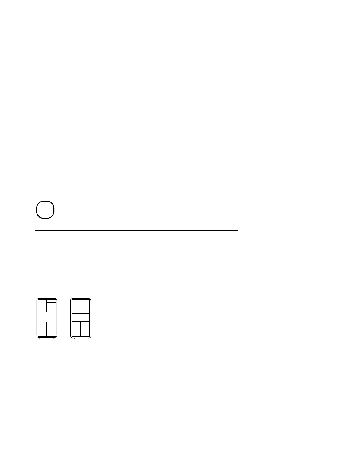
Icons. Icons such as those shown below are used in illustrations for designating part placement in the system described. A shaded area in the icon
shows the location of the component or part being discussed.
systems.
Documentation Titles
Table 1 lists the books in the DEC 10000 and VAX 10000 documentation
set. Table 2 lists other documents that you may find useful.
viii
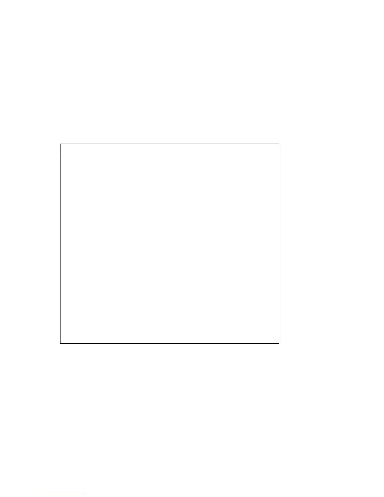
Table 1 DEC 10000/VAX 10000 Documentation
Title Order Number
Installation Kit
EK–1000B–DK
Site Preparation Guide
EK–1000B–SP
Installation Guide
EK–100EB–IN
Hardware User Information Kit
EK–1001B–DK
Operations Manual
EK–1000B–OP
Basic Troubleshooting
EK–1000B–TS
Service Information Kit—VAX 10000
EK–1002A–DK
Platform Service Manual
EK–1000A–SV
System Service Manual
EK–1002A–SV
Pocket Service Guide
EK–1000A–PG
Advanced Troubleshooting
EK–1001A–TS
Service Information Kit—DEC 10000
EK–1002B–DK
Platform Service Manual
EK–1000A–SV
System Service Manual
EK–1002A–SV
Pocket Service Guide
EK–1100A–PG
Advanced Troubleshooting
EK–1101A–TS
ix

Table 1 DEC 10000/VAX 10000 Documentation (Continued)
Title Order Number
Reference Manuals
Console Reference Manual
EK–70C0B–TM
KA7AA CPU Technical Manual
EK–KA7AA–TM
KN7AA CPU Technical Manual
EK–KN7AA–TM
MS7AA Memory Technical Manual
EK–MS7AA–TM
I/O System Technical Manual
EK–70I0A–TM
Platform Technical Manual
EK–7000A–TM
Upgrade Manuals
KA7AA CPU Installation Card
EK–KA7AA–IN
KN7AA CPU Installation Guide
EK–KN7AA–IN
MS7AA Memory Installation Card
EK–MS7AA–IN
KZMSA Adapter Installation Guide
EK–KXMSX–IN
DWLMA XMI PIU Installation Guide
EK–DWLMA–IN
DWMBB VAXBI PIU Installation Guide
EK–DWMBB–IN
H7237 Battery PIU Installation Guide
EK–H7237–IN
H7263 Power Regulator Installation Guide
EK–H7263–IN
BA654 DSSI Disk PIU Installation Guide
EK–BA654–IN
BA655 SCSI Disk and Tape PIU
Installation Guide
EK–BA655–IN
Removable Media Installation Guide
EK–TFRRD–IN
x
Table 2 Related Documents
Title Order Number
General Site Preparation
Site Environmental Preparation Guide
EK–CSEPG–MA
System I/O Options
BA350 Modular Storage Shelf Subsystem
Configuration Guide
EK–BA350–CG
BA350 Modular Storage Shelf Subsystem User’s
Guide
EK–BA350–UG
BA350-LA Modular Storage Shelf User’s Guide
EK–350LA–UG
CIXCD Interface User Guide
EK–CIXCD–UG
DEC FDDIcontroller 400 Installation/Problem
Solving
EK–DEMFA–IP
DEC LANcontroller 400 Installation Guide
EK–DEMNA–IN
DEC LANcontroller 400 Technical Manual
EK–DEMNA–TM
DSSI VAXcluster Installation and Troubleshooting
Manual
EK–410AA–MG
InfoServer 150 Installation and Owner’s Guide
EK–INFSV–OM
KDM70 Controller User Guide
EK–KDM70–UG
KFMSA Module Installation and User Manual
EK–KFMSA–IM
KFMSA Module Service Guide
EK–KFMSA–SV
RRD42 Disc Drive Owner’s Manual
EK–RRD42–OM
RF Series Integrated Storage Element User Guide
EK–RF72D–UG
TF85 Cartridge Tape Subsystem Owner’s Manual
EK–OTF85–OM
TLZ06 Cassette Tape Drive Owner’s Manual
EK–TLZ06–OM
xi

Table 2 Related Documents (Continued)
Title Order Number
Operating System Manuals
Alpha Architecture Reference Manual
EY–L520E–DP
DEC OSF/1 Guide to System Administration
AA–PJU7A–TE
DECnet for OpenVMS Network Management Utilities
AA–PQYAA–TK
Guide to Installing DEC OSF/1
AA–PS2DA–TE
OpenVMS Alpha Version 1.0 Upgrade and
Installation Manual
AA–PQYSA–TE
VMS Upgrade and Installation Supplement:
VAX 7000–600 and VAX 10000–600 Series
AA–PRAHA–TE
VMS Network Control Program Manual
AA–LA50A–TE
VMSclusters and Networking
HSC Installation Manual
EK–HSCMN–IN
SC008 Star Coupler User’s Guide
EK–SC008–UG
VAX Volume Shadowing Manual
AA–PBTVA–TE
Peripherals
Installing and Using the VT420 Video Terminal
EK–VT420–UG
LA75 Companion Printer Installation and User Guide
EK–LA75X–UG
xii

Chapter 1
Adding or Replacing
CPUs and Memories
This chapter provides information on how to remove and install processor
and memory modules in DEC 10000 and VAX 10000 systems. Sections include:
• What Is Required
• LSB Configuration Rules
• Identifying the Kernel FRUs
• Removing a Module from the LSB Card Cage
• Inserting a Module in the LSB Card Cage
• Verifying the System
For information on servicing I/O modules and batteries, see the Platform
Service Manual; it also describes removal and replacement of the LSB
centerplane and card cage (Part No. 70-28574-01), the IOP module (Part
No. E2044-AA), and all power system FRUs.
Adding or Replacing CPUs and Memories 1-1
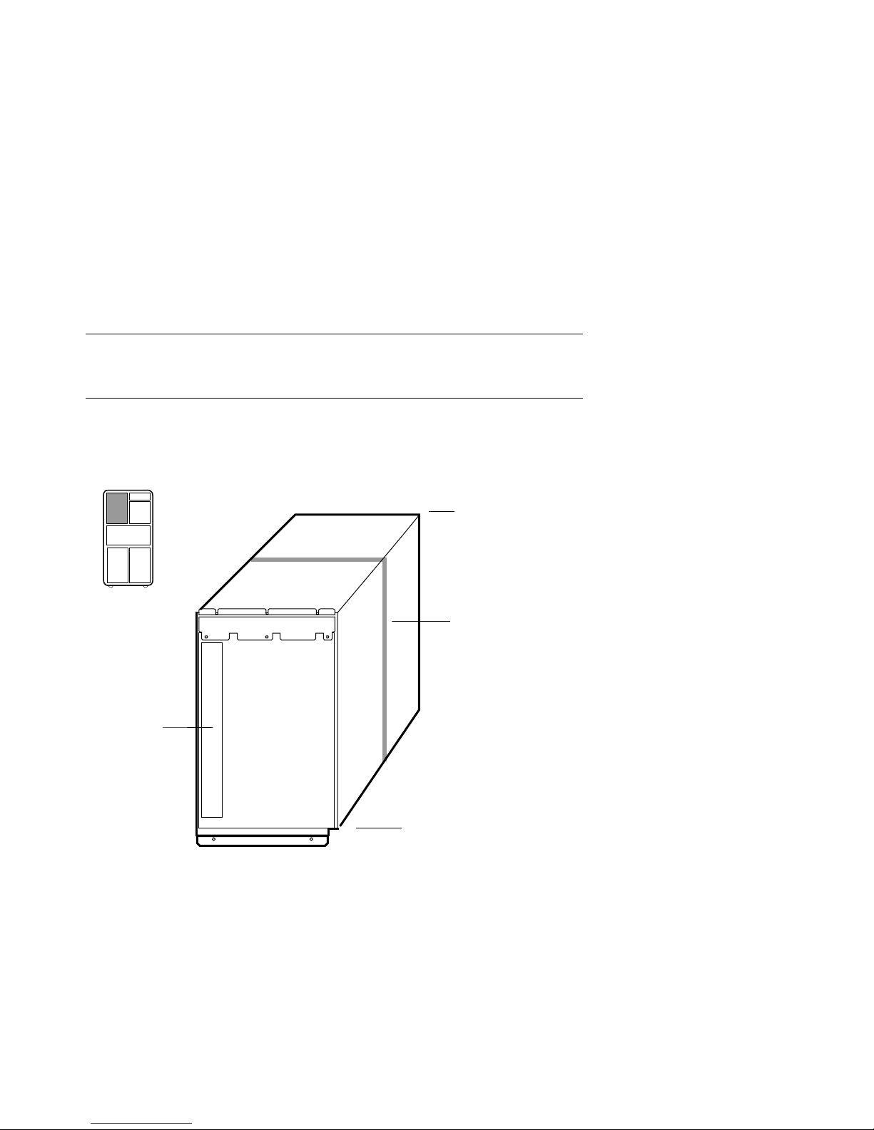
1.1 What Is Required
System
Cabinet
Front
Slots
Slots
BXB-0088B-92
Centerplane
Power
Filter
Adding or replacing processor or memory modules is a simple operation. Afterward you must verify that the new modules are recognized in the system. You may need to set system parameters.
Figure 1-1 LSB Card Cage
1-2 Adding or Replacing CPUs and Memories

Processor and memory modules reside in the LSB card cage, a centerplane
For more information:
Basic Troubleshooting
Advanced Troubleshooting
card cage in the system cabinet with nine slots for modules. The LSB card
cage always contains an IOP module, a clock module, and at least one processor and one memory module (see Figure 1-1).
To add or replace modules, you will follow the steps in Sections 1.2 through
1.6. Then you will:
• Set system parameters to the original operating environment
(Chapter 2).
• Upgrade firmware if required (Chapter 3).
Adding or Replacing CPUs and Memories 1-3
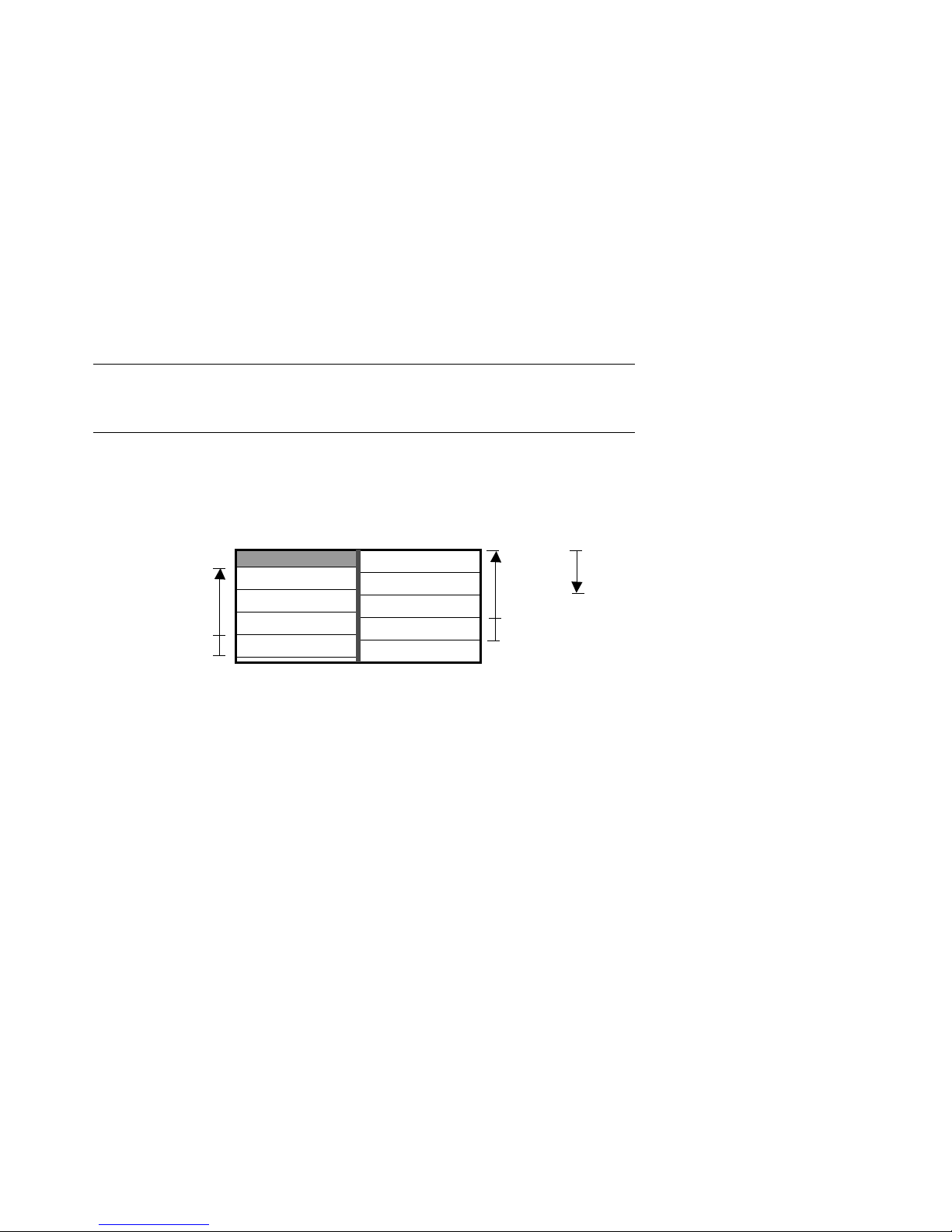
1.2 LSB Configuration Rules
BXB-0094-92
Front Rear
4
5
6
7
8
0
1
2
3
First CPU
Additional CPUs
or Memories
Power Filter
IOP Module
First Memory
Additional
Memory
Centerplane
Additional
CPUs
The first CPU module is node 0, and the first memory module is at
node 7. The LSB bus requires that an IOP module be at node 8.
See Figure 1-2.
Figure 1-2 LSB Configuration Rules
1-4 Adding or Replacing CPUs and Memories
The LSB card cage (see Figure1-2) has nine slots. Slot numbers are
For more information:
Platform Service Manual
KN7AA CPU Technical Manual
KA7AA CPU Technical Manual
MS7AA Memory Technical Manual
Front Rear
4
5
6
7
8
0
1
2
3
BXB-0094A-92
1st CPU
2nd CPU
3rd Memory
Filler Module
IOP Module
1st Memory
2nd Memory
4th Memory
Filler Module
Centerplane
equivalent to node numbers. Four slots are at the front of the cabinet
(nodes 0 through 3, right to left), and five slots are at the rear (nodes 4
through 8, right to left).
A system can have up to six processors and up to seven memory modules,
as space allows. The maximum memory configuration is bounded by the
operating system support and the physical slots.
• The first CPU module is installed in node 0 (in the front at the far
right).
• Additional CPU modules are installed in slots 1 through 5.
• The IOP module is in node 8.
• The first memory module is in node 7.
• Additional memory modules are installed next to filled slots. Modules
are installed contiguously to the centerplane of the card cage. Install
additional memories alternating between installation from the front
and the back of the cabinet (see the example below of a 2 processor, 4
memory system).
• Install filler modules in all empty slots to direct the airflow through
the card cage.
Figure 1-3 Sample Configuration—2 Processors, 4 Memories
Adding or Replacing CPUs and Memories 1-5
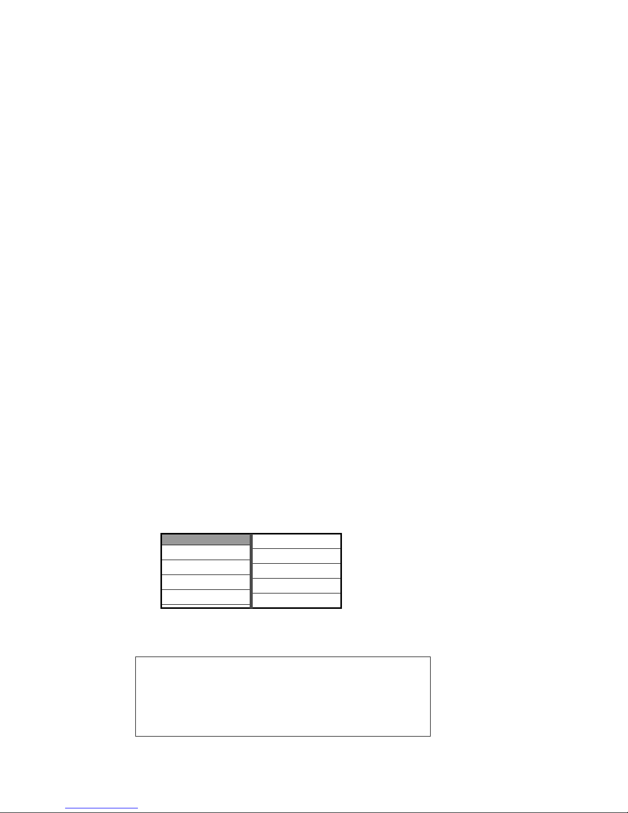
1.3 Identifying the Kernel FRUs
Option No. Part No. Description
KN7AA-AB
E2040-AB DEC 10000 CPU module
KA7AA-AA
E2045-AA VAX 10000 CPU module
MS7AA-AA
E2043-AA 64-Mbyte memory module
MS7AA-BA
E2043-BA 128-Mbyte memory module
MS7AA-CA
E2043-CA 256-Mbyte memory module
MS7AA-DA
E2046-AA 512-Mbyte memory module
Table 1-1 lists the field-replaceable units (FRUs) for DEC 10000
and VAX 10000 systems that are discussed in this book.
Table 1-1 Field-Replaceable Units
Removal and replacement of the LSB centerplane and card cage (Part No.
70-28574-01), the IOP module (Part No. E2044-AA), and all power system
FRUs are described in the Platform Service Manual.
1-6 Adding or Replacing CPUs and Memories
Each memory or processor board is enclosed in the module case, protect-
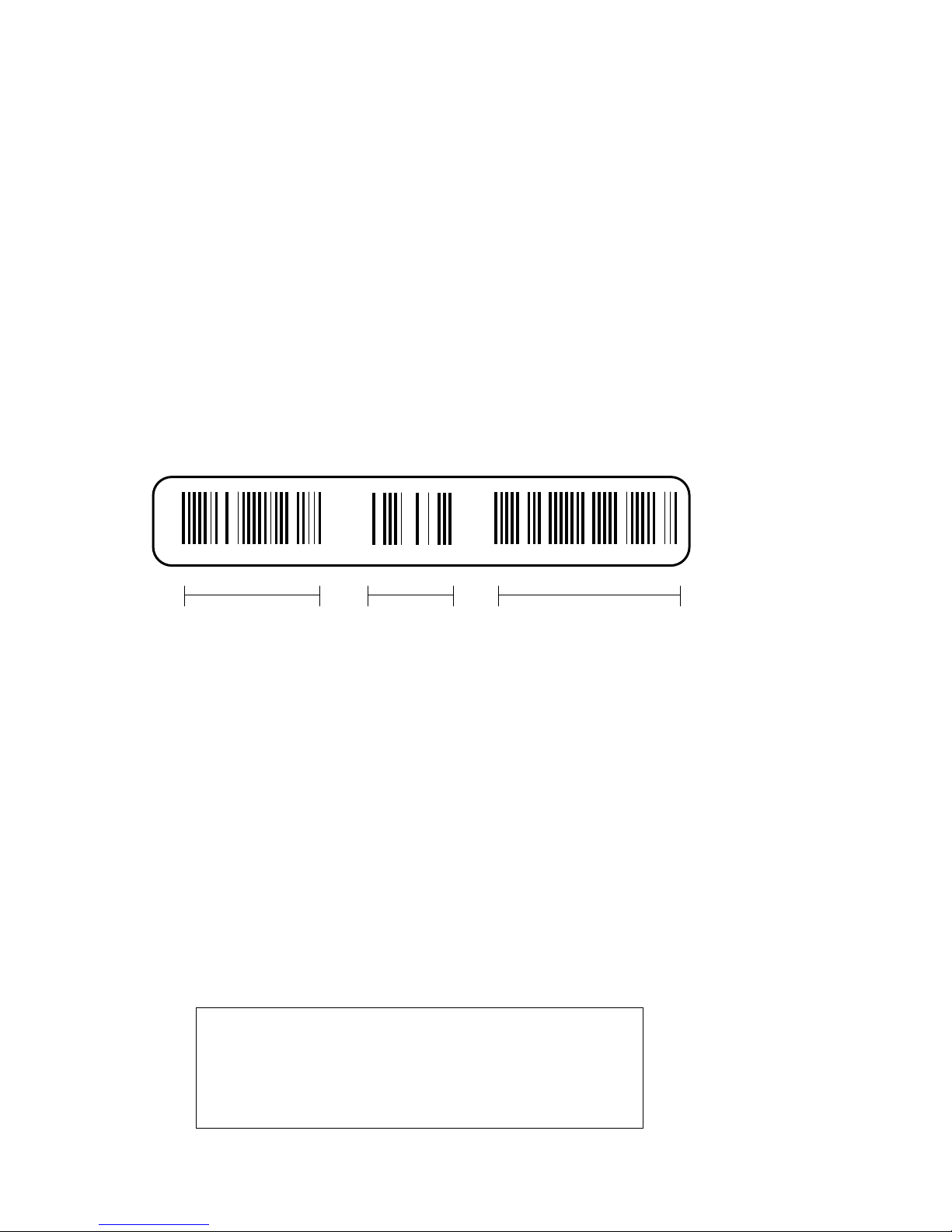
E2043-AA E04 GAO1234567
Module
Part Number
Revision
Level
Module
Serial Number
BXB-0089-92
For more information:
Platform Service Manual
ing the module electronics from static discharge. A barcode label gives information about the module, including the module part number, revision
level, and the module serial number (see Figure 1-4).
Figure 1-4 Module Barcode
Adding or Replacing CPUs and Memories 1-7
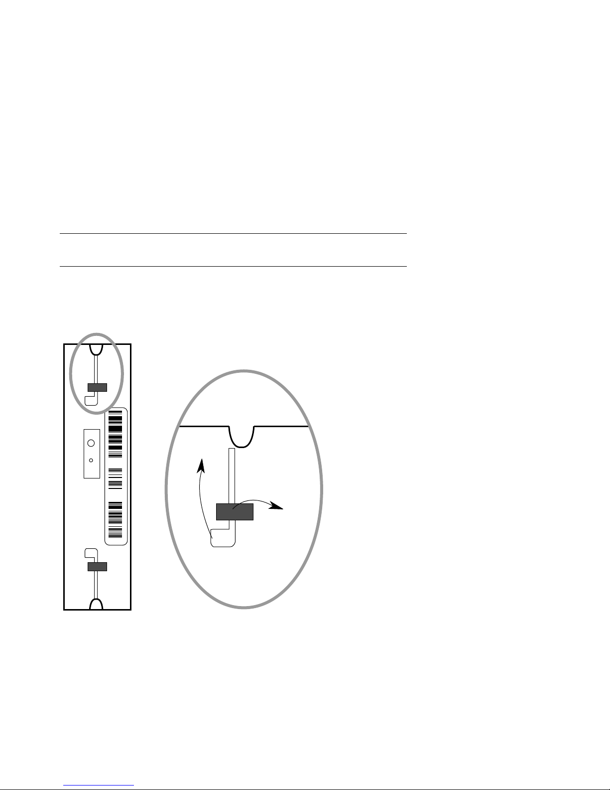
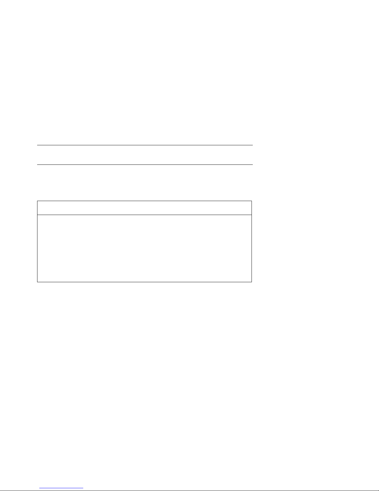
1.4 Removing a Module from the LSB Card Cage
E2043-AA E 04 SGO1234567
BXB-0090B-92
2.
1.
Use the following procedure to remove a module from the LSB
card cage for replacement or reconfiguration.
Figure 1-5 Removing a Module from the LSB Card Cage
1-8 Adding or Replacing CPUs and Memories

1. Perform an orderly shutdown of the system.
For more information:
Platform Service Manual
2. Turn the keyswitch on the front control panel to the Disable position
and wait for the control panel yellow Fault LED to stop flashing.
When the Fault LED stops flashing, power has been removed from
the LSB backplane and you may safely proceed.
3. Open the cabinet door by holding the recessed handhold and pulling
the door out toward you.
4. Put on the antistatic wrist strap.
CAUTION: You must wear a wrist strap when you handle any modules.
5. Release the plate covering the LSB card cage by loosening the two
thumbscrews on the end of the plate. The plate is connected to the
card cage by a cable; let the plate swing to one side.
6. On the module you are removing, use your thumbs to pull the two
black restraining clips out and to the right (see Figure 1-5, step 1).
The clips snap when they open.
7. Pull both levers out at the same time until they are perpendicular to
the front of the module (see Figure 1-5, step 2). This frees the module
from the backplane.
8. Holding the levers, pull on the module until it is out far enough to hold
it underneath as you remove it.
9. When the module becomes free of the card cage, hold it with both
hands, and place the module on an ESD pad in a safe area. If the
module is being replaced, pack the module in the box from the new
module.
Adding or Replacing CPUs and Memories 1-9
 Loading...